1. Introduction
Today, at least 12 plate Mills 5000 are operated worldwide, five of which are in Japan, three in Germany, three in the Russian Federation, and one in Shanghai (BAOSTEEL, China). They are designed to produce flats of up to 5 m in width and up to 36 m in length. Such rolling mills are the main suppliers of rolled products for large diameter pipes, used to build oil and gas pipelines.
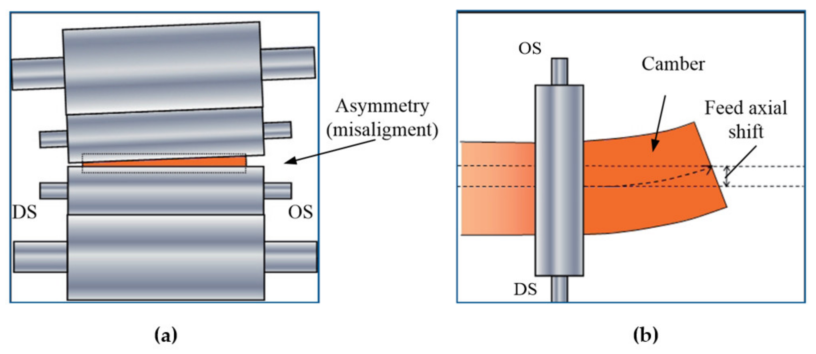
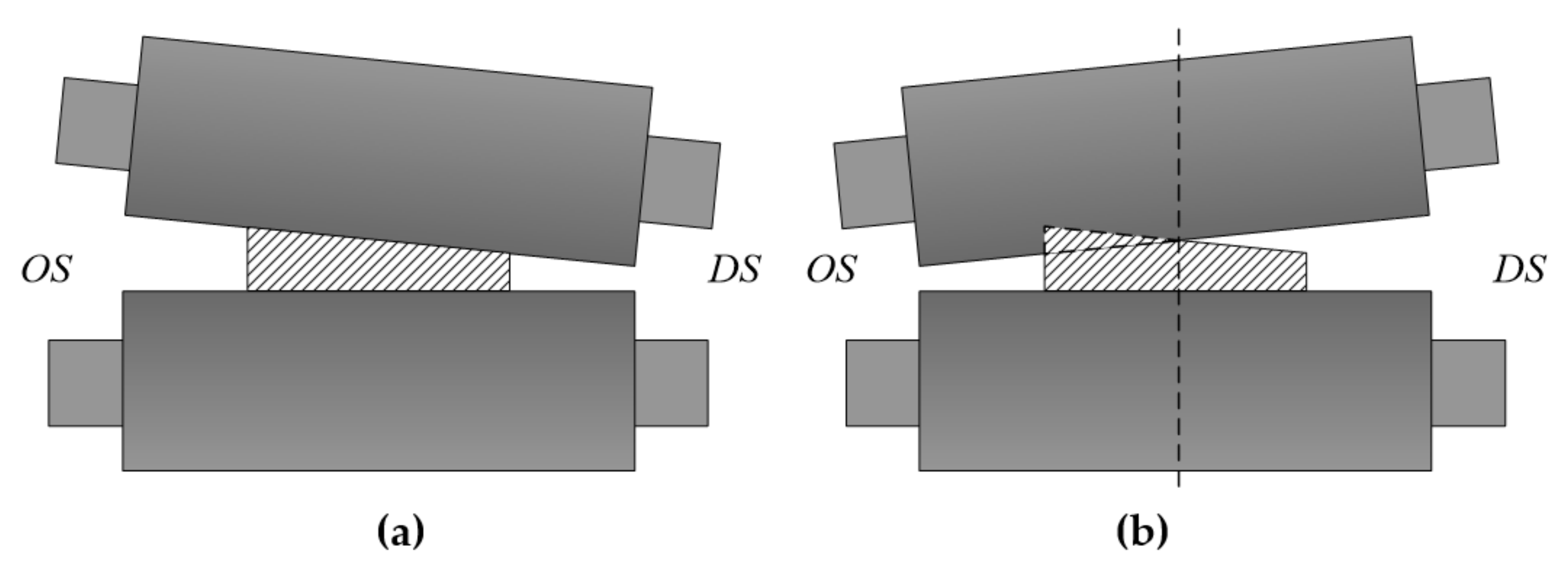
High product quality is the most important requirement to rolling production units. The requirement is also relevant for heavy-plate rolling mills, including Mill 5000 at PJSC “Magnitogorsk Iron and Steel Works” (MMK PJSC). The key quality requirement is the geometric precision of the finished sheet or plate and minimum edge trimming. This is attained by automated electric drives and process parameter control systems. The most commonly occurring feed (intermediate product between plate slab and ready sheet) defect are the bend in the motion plane (defect “camber”
Figure 1b) and its lateral shift at the output of the stand [
1,
2,
3].
Horizontal bend is induced in the strip by strain difference in cross section (
Figure 1a) which leads to elongation difference. Such differential elongation manifests itself as feed strain causing lateral and angular shift as shown in
Figure 1b [
3]. Both defects cause the loss of output product quality, and at larger deviations they can lead to the mill emergency shutdown. This explains the relevance of conducting the research, intended for the elimination of specified drawbacks.
Many authors’ works prove the relevance of the issue. Thus, paper [
4] presents a case study of a mill operated by Tata Steel (Port Talbot, Wales), which shows that the longitudinal shape of the feed is a distorted passage from the passage during roughing. Paper [
5] shows the curve of the axial shift of the feed at Mill 2250 (China) as a function of the length of rolled feed. The plate deviates by as much as 15 mm from the rolling axis, which the paper states is unacceptable for this grade of product. Paper [
6] presents a similar study for Mill 1580.
Online camber measurement is utilized to prevent accidents such as collisions with the guiding rail or runoff from the roller table. These measurements control the force of the hydraulic screw-downs (SD) or the side guides [
2]. However, camber measurement equipment, which is usually based on light sensors [
7], can be installed on a unit-by-unit basis and is not available on every rolling mill. Solutions to the problem are covered in patents [
8,
9].
The research of most authors, including [
10,
11], showed that the feed cross section and, correspondingly, the sheet final form depend on the difference of forces formed by a hydraulic cylinder at driving (DS) and operated sides (OS). The references suggest various technical solutions for increasing the precision and expanding functional possibilities of the control systems for roll gap misalignment. Thus, in [
12], to minimize DS-OS differences in relation to roll shift level, a control system with the use of the model predictive controller (MPC) was developed. The tilt controller responds to the pressure deviations in the initial phase of the gap misalignment. Control is based on measuring the difference of torsional forces on OS-DS without the application of additional control and measurement instrumentation. In real time operation, this model calculates the incline corrections, minimizing the force difference during bending at the compliance of maximum action limitations. It is stated that MPC application can bring about some advantages comparing with conventional controllers (PI or PID) because of the function of forecasting force difference along the gap width. The controller has been implemented in the Level 1 software of the hot strip mill of Tata Steel in IJmuiden, the Netherlands. However, according to [
12], this technical solution is at the approbation stage and has not been industrially introduced yet.
The papers [
9,
13] as well as the R&D works of SMS [
14] suggest solving the problem by aligning massive lateral guiding fences, located before and after the stand, and the roll hydraulic installation mechanism. This solution is prospective, however, research should be conducted in depth in each specific case. This results in roll gap misalignment, which causes the increase of gauge variation on the feed gauge as well as lateral shift in relation to the rolling axis. The aforementioned drawbacks cause deterioration in the sheet quality. That is why it is necessary to develop technical solutions for their elimination.
The analysis of the presented and other publications confirms the relevance of enhancing the system of compensation of the misalignment of rolls at the heavy-plate rolling mill stand. This solution must be efficient and should not require critical changes of control algorithms.
The paper is structured as follows.
Section 2 explains why the issue is relevant, describes the object of research briefly, and rationalizes the effort to address the weaknesses of the existing rolling direction control algorithm.
Section 3 makes a case for, and describes the development of, a control system that handles the lateral asymmetry of the feed in the reversing stand of a plate mill.
Section 4 presents a method for predictive roll-gap asymmetry control, validates the use of PD RAC controllers, and discusses a simulation model of the connected screwdown positioning systems.
Section 5 presents the results of mathematical modeling and experiments.
Section 6 discusses the results, and the
Section 7 draws conclusions.
2. Problem Formulation
The main technical means of the rolling Mill 5000 is a superpowered reversing rolling stand, providing rolling force up to 12,000 t (
Figure 2). The stand rolls are driven by synchronous electric motors, installed on the driving side (DS) at the machine room—left to the stand in
Figure 2. The opposite side is called non-driving, or the operating side (OS). Here the operator’s board is located which is why the abbreviation OS is sometimes read as the operator’s side.
Compliance with strict requirements for the released products is guaranteed by automated electric drives and systems of technologic automation. The most important of the latter are automatic control systems for roll gap and gauge [
15]. In total, they implement the gauge control concept ROLL-GAP CONTROL developed by SMS Demag AG. This concept was considered in the publications [
16,
17,
18,
19] and fully implemented at the mill.
The roll gauge and gap control principles are shown in the functional diagram, see
Figure 3. It consists of the following basic systems (modules) [
1]:
hydraulic gap control (HGC);
automatic gauge control (AGC);
roll alignment control (RAC);
dynamic disturbance compensation (DDC).
Fundamental to the structure are the two control circuits: the internal circuit to control the positioning of hydraulic screw-down mechanisms and the external gauge control system. The ultimate function is to compensate the stand strains and various disturbances caused by deviations in the process parameters, which might occur during rolling. Aside from these modules, the structure includes systems for electromechanical pressure screw (EMP) positioning and conicity control; however, this paper does not dwell upon such systems.
Since it is impossible to measure the actual roll gap during rolling, the system computes it. To that end, we use the gap equation:
Therefore, the roll gap
h depends on the hydraulic cylinder piston position
S and the stand stretching
g, which is a function of the rolling force
FW. The AGCS should compensate the stand stretching fluctuations caused by the rolling process according to the equation
Successful use of such systems on Mill 5000 proves their reliability and the high precision of set parameters’ adjustment.
To eliminate the aforementioned drawbacks at Mill 5000, the structure, implementing the concept ROLL-GAP CONTROL, includes the controller of rolling direction (roll alignment control—RAC controller). Its function is to guarantee the constant width of roll gap (roll parallel alignment) at various rolling condition violations. Such controllers are applied in roughing trains of wide-strip rolling mills. Their development is presented in national and foreign publications [
20,
21,
22]. Most known solutions are based upon the elimination of force imbalance occurring in cylinders on DS and OS at the deviations of rolling parameters and temperature imbalance on feed width.
During the operation of the rolling Mill 5000, the authors identify the drawbacks of the existing settings of the RAC controller. The main ones are slow response and misalignment of hydraulic SD shift along DS and OS. Here are the steps towards addressing these shortcomings:
Develop a method for controlling hydraulic SDs to compensate the asymmetry by resetting the roll gap in the pauses between passages (predictive control).
Develop a screw-down control method that can compensate for the ‘ongoing’ asymmetry of the roll gap that emerges during rolling.
Test the feasibility of a transfer function and RAC configuration intended for faster response coupled with sustainable control process.
These objectives will further the ROLL-GAP CONTROL concept (control of the gauge and gap between the rolls in a stand). The concept is the foundation of control algorithms used in many plate and broad-strip mills. Thus, the contribution of this paper and studies it presents consists in a quality improvement of the products made on such mills.
3. Materials and Methods
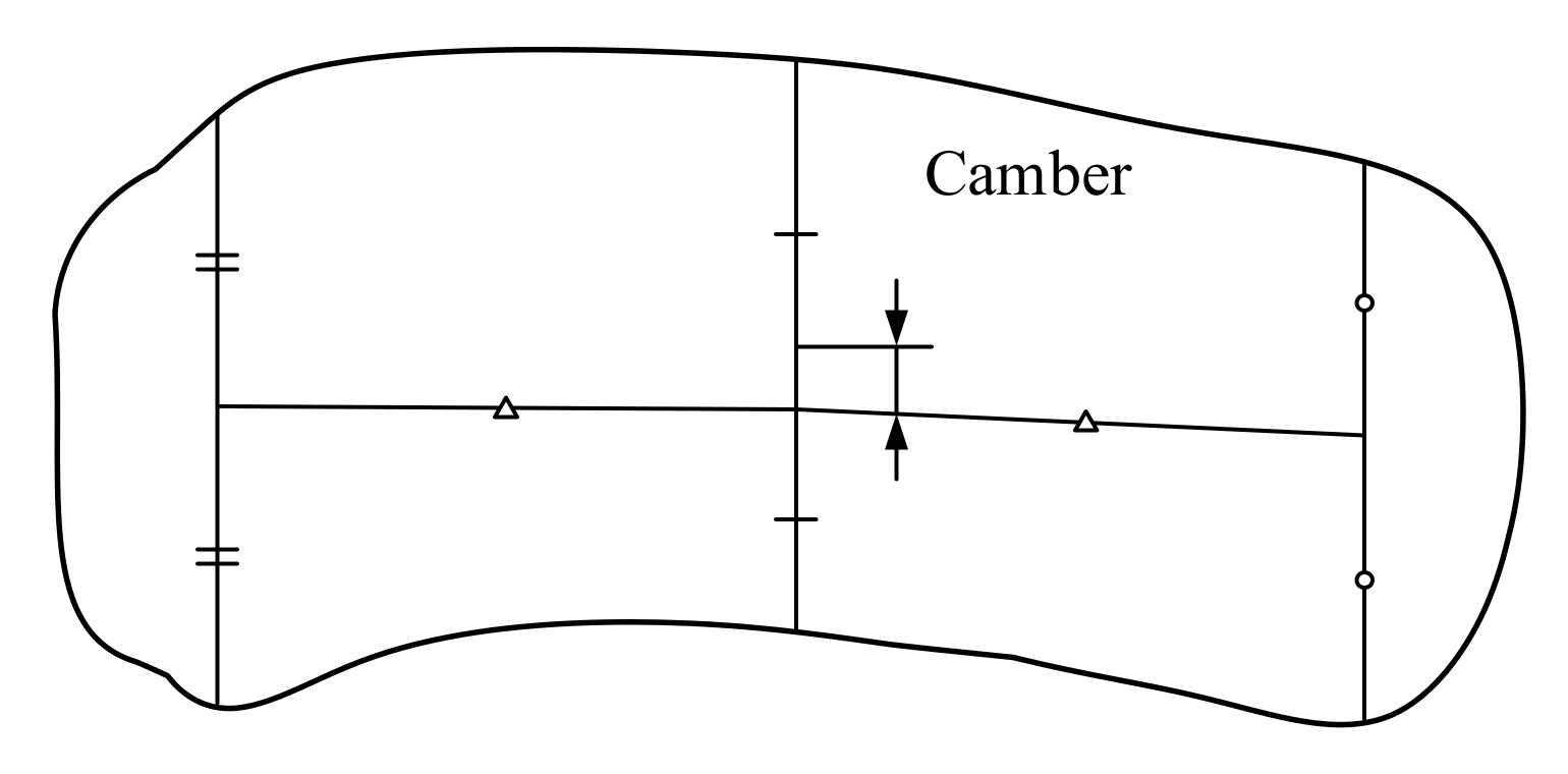
3.1. Camber Characteristics
Quantitatively, camber is defined as curvature of the rolled plate’s axis as shown by the sketch in
Figure 4. Permissible camber for the flats rolled by Mill 5000 depend on the rolled length, see
Table 1. These values are cited from the German SMS Group’s standards; the Group is the designer and supplier of Mill 5000. Assessments ignore 1 m from the beginning and 1 m from the end of the strip.
Testing more than 1000 plates showed the actual deviations in the feed axis position to be 1.5 to 2 times the acceptable limit for some profiles. This proves the relevance of finding the causes of this defect and addressing it.
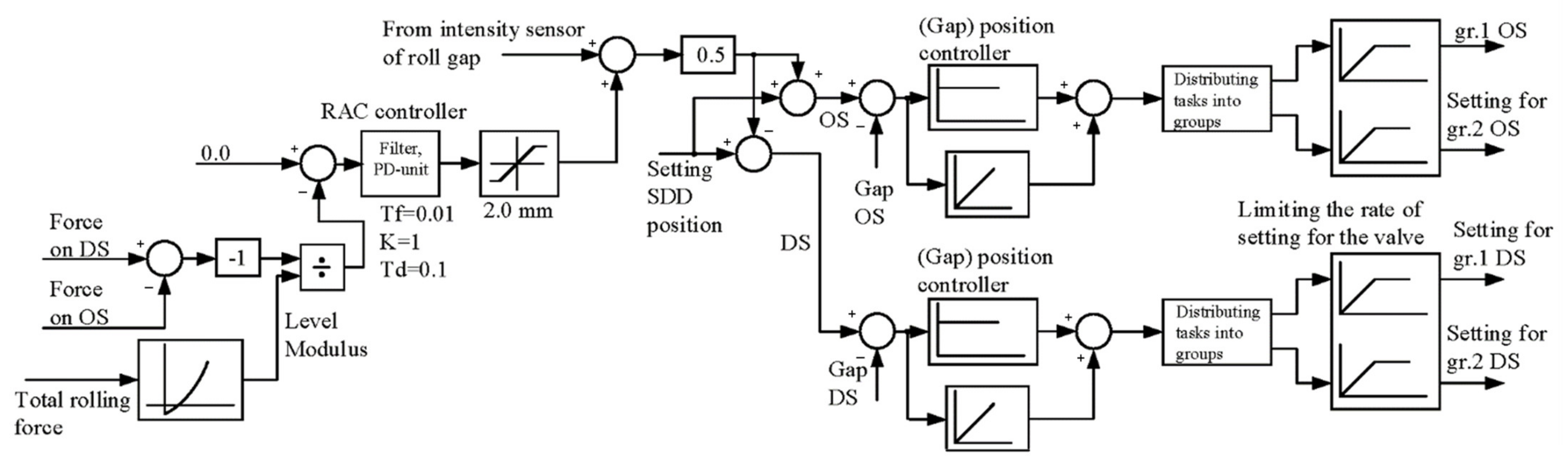
3.2. Transverse Profile Asymmetry Control System for the Reversing Stand of Mill 5000
The diagram of the control system intended for the compensation of the feed profile deviation is provided in
Figure 5. The system provides the alignment of stand strain in the cases when the forces on DS and OS differ. To do this, a zero signal is sent to the RAC controller input which is compared with the actual gap values on the operator and drive sides. On the forces in hydraulic cylinders the setting for gauge differences at the workpiece edges is formed and, correspondingly, the setting for the gaps on DS and OS. This value is calculated by means of the measured force division by the strip elasticity module (Level Modulus). The curve of elasticity module dependence on the force is stored in the form of the table in the file of CAPCS. The difference of forces is divided by the elasticity module on one side of the stand and impacts the position of hydraulic SDs.
At the output of the RAC controller a setting is established which is sent to SDD position and compensates gauge variation. To eliminate inadmissible gap misalignment, one should set the limitation of the output signal. This is necessary because of the risk of upper and lower roll edge contact at thin feed rolling and significant misalignment. The set limitation is within the range 0.7–2 mm and depends on the rolled profile.
During the system setting the authors give a rationale for applying a proportional and differential RAC controller which in fact controls the filtered derivative value of the input signal. This controller is selected because such controllers facilitate the control action formation taking into account both the error and the speed of its change. The introduced derivative control speeds up the system response time. This reduces the number of errors in the dynamic mode caused by the shift of screw-down mechanisms.
The output signal of the (gap) position controller provides for the control of the task on the hydraulic cylinder servo-valve in the range ±100% in relation to the zero value. To work out the range at each hydraulic cylinder of screw-down devices (on DS and OS), two servo-valves are installed. They are connected to the head end in parallel and maintain the total range of pressure control in the hydraulic cylinder of ±200%. These valves are united into two groups (gr. 1 and gr. 2 in
Figure 5). Each group includes one valve, installed on hydraulic cylinders on the sides DS and OS. Depending on the value of the shift signal, received from the output of the position controller, the group. 1 or group. 2 valves are put into operation or the valves of two groups simultaneously. The valve groups are brought into operation by the block “Distributing tasks into groups”. Such a control algorithm allows maintaining necessary (high) shift speeds as well as increasing the reliability and sustainability of the control.
More detailed research on the RAC controller operation and the automatic gauge control system (AGCS) is provided in [
16,
23].
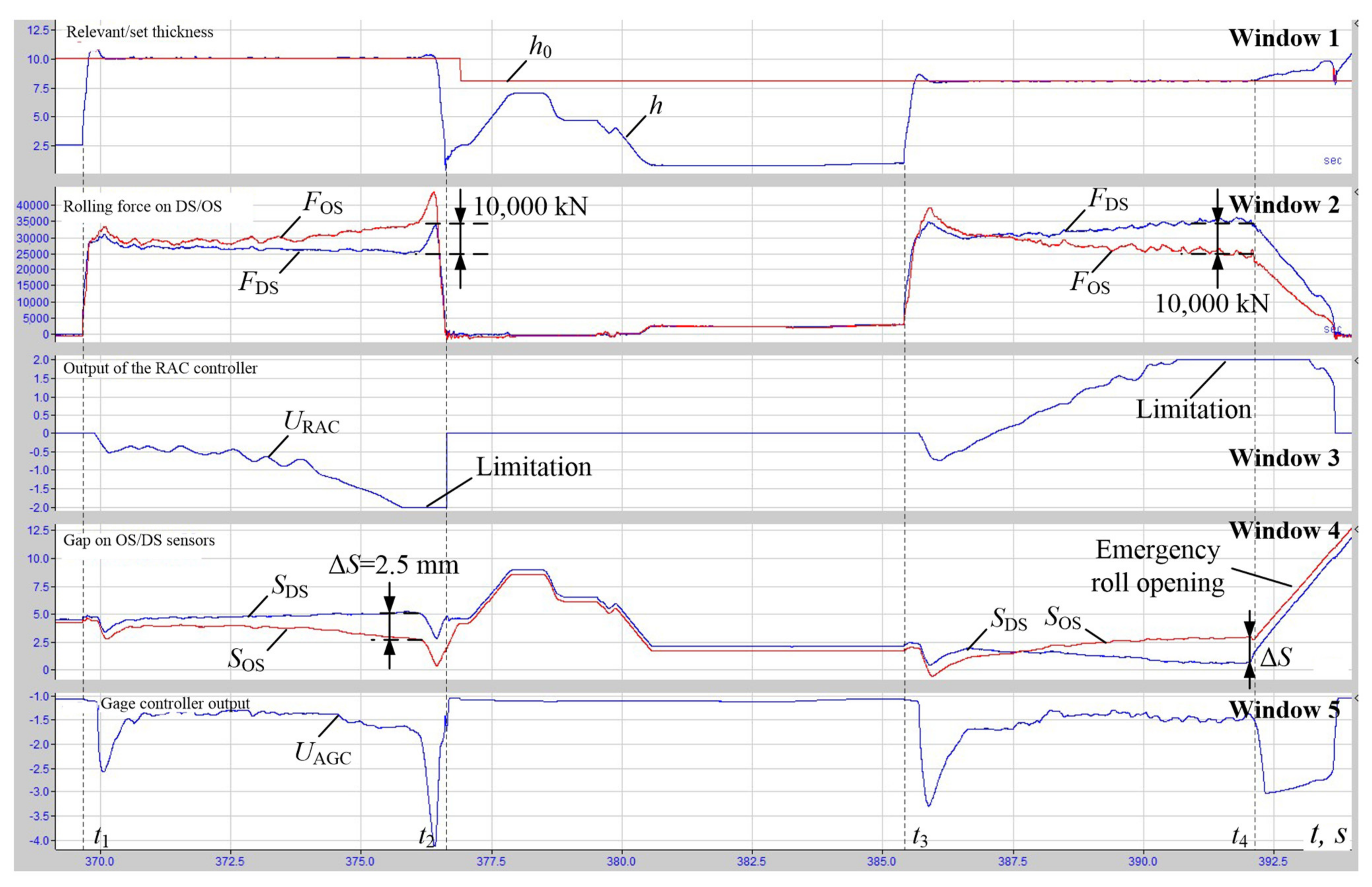
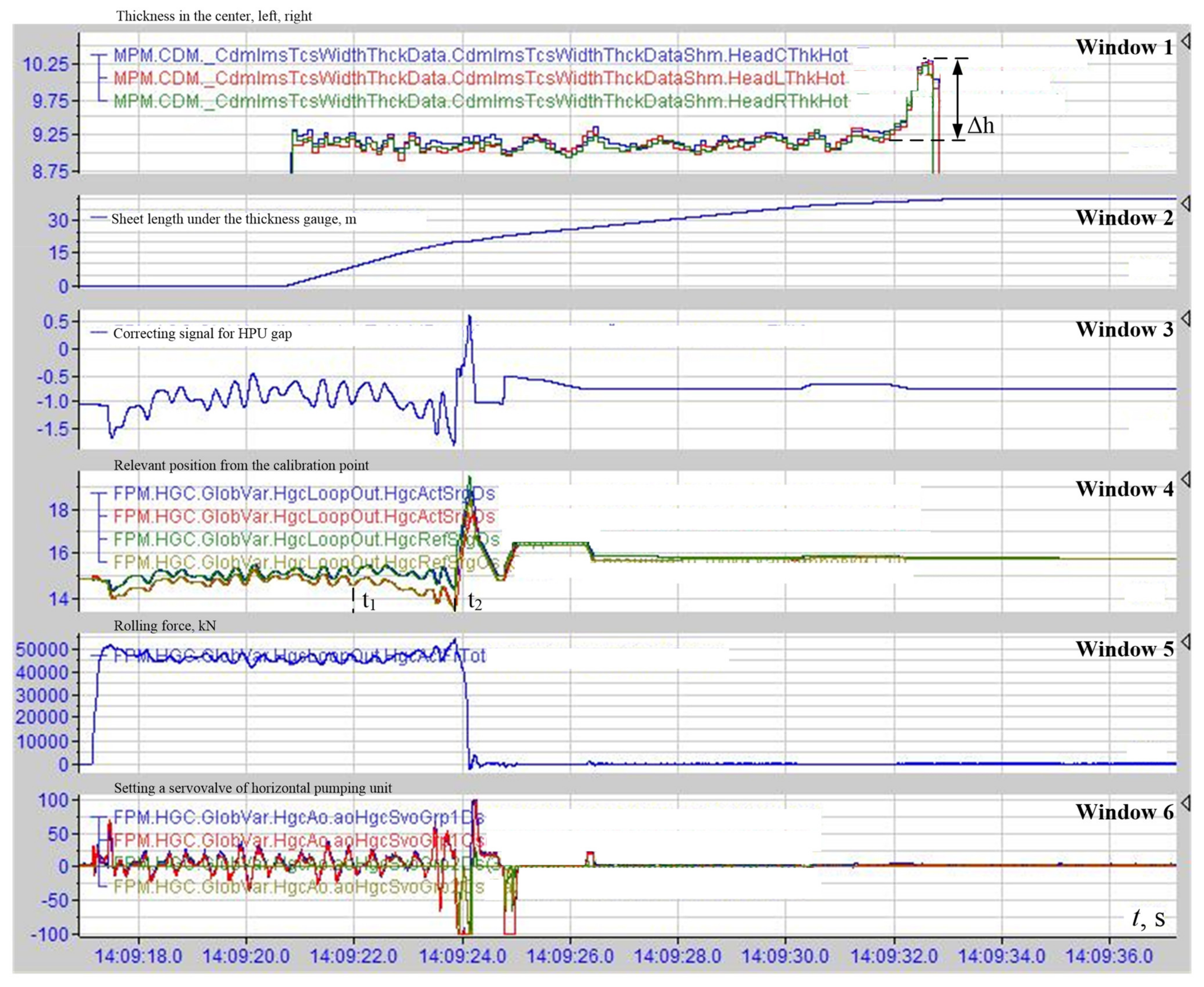
3.3. Analysis of Oscillograph Records at Design Setting of the RAC Controller
Figure 6 gives the oscillograph records showing changes in gauge and coordinates of hydraulic SDs on DS and OS registered at the rolling in the passages with roll gap misalignment control. Window 1 gives the curves of setting
h0 and an actual gauge
h of the feed at stand output. Window 2 shows rolling forces on the sides (
FDS and
FOS) which change in the rolling process. Windows 3 and 5 show output signals of the RAC controller
URAC and the gauge controller
UAGC, window 4 shows values of roll gaps
SDS and
SOS. The dimensions on the axes in windows 1, 3–5 are given in mm, the rolling forces dimensions in the second window in kN.
The present oscillograph records demonstrate the operation of the RAC controller at design setting: it has a control action on the SDs with a larger force. Thus, in the first passage (interval t1–t2) it “clamps” feed on OS. The gap SOS (window 4) is reduced while the force FDS (window 2) and the size of the gap SDS on the opposite side remain virtually constant. In the second passage (interval t3–t4) one can observe the opposite: the gap SDS decreases while the action on SOS is not so intensive. The misalignment ΔS at the end of passages is 2.5 mm, the force difference on the passages FOS-DS = 10,000 kN, and at the end of the first passage FOS > FDS. This ratio is the opposite at the end of the second passage. Such non-uniform distribution of control actions makes the response slower and reduces the efficiency of roll gap alignment. A large imbalance of forces in both passages results in the limitation on the RAC controller (window 3). As a result, in the second passage the emergency roll opening occurs (pointed by an arrow). This leads to the rejection of the workpiece being rolled and production losses.
In compliance with the design solution, in the structure in
Figure 5 a proportional RAC controller is applied. However, the operation reveals its drawback: unsatisfactory control response. This causes continuous rolling force imbalance, which is confirmed by the oscillograph records in
Figure 6.
Obviously, simultaneous formation of control actions on the position controllers of both SDs with opposite signs is more efficient. However, gain factors should be the same. The distribution of drive signals must be conducted with the coefficients 0.5. These conditions are necessary for providing the equality of statistical errors of the SD position control on OS and DS at the absence of a signal at the RAC controller output. Such a signal setting is shown in the diagram,
Figure 5.
In connection with the aforementioned the authors revealed the need to develop a control method for controlling the position of both SDs and changing the RAC controller settings. The solution of these objectives is considered below after presenting the developed method of controlling the transverse asymmetry of the gauge profile, based upon the principle of control action redistribution.
4. Implementation
4.1. Predictive Control of Asymmetry of Roll Gap of the Heavy-Plate Mill Stand
The authors developed a way of controlling the roll gap misalignment, the key idea of which consists in measuring the differential rolling force and calculation of the back pressure value used as control action. To implement the method, the following operations are conducted:
The change in rolling forces (pressure in hydraulic cylinders on the sides OS and DS) and the calculation of its difference (differential rolling force).
The calculation of pressure values on the sides OS-DS (counter-pressures), which should be generated in hydraulic cylinders to compensate differential force.
The use of the signal, proportional to the counter-pressure difference, as control action in the RAC controller.
A half of this value is used as additional action for controlling the SD position on each DS and OS. Received signals compensate stand transverse tension, occurring as a result of differential force action, and thus compensate gap asymmetry. In effect, the authors develop a method of direct feedback ensuring the control of the gauge profile transverse asymmetry on disturbance.
Studies carried out by the authors of [
24,
25] showed the difference in the output gauge on the sides of the feed to have the greatest influence on the pressure mismatch. Unless control actions are applied, this difference ‘builds up’ after each passage, i.e., is inherited. Tests on Mill 5000 confirm this conclusion. This is where the idea behind the predictive control of roll gap misalignment in reverse rolling came from.
Figure 7 shows schematically the principle of compensating inherited feed asymmetry. The idea is to store the DS and OS force values at the end of the forward passage (
Figure 7a) and force the reverse misalignment of rolls before the reverse passage,
Figure 7b. During the reverse, we compute (predict) the SD positions. This is from where the name derives: the predictive method.
The prototype of the developed technical solution is the method of strip hot rolling in compliance with the patent of the Russian Federation [
8]. It suggests using a controlling change of roll gap in the function of temperature difference of the feed left and right edges. Temperature is measured by pyrometers installed on the sides of the stand. Below is the function that computes the roll gap asymmetry, mm:
where
R is the work roll radius, mm; Δ
h is the absolute compression;
B is the feed width, mm;
CK is the housing stiffness, t/mm; Δ
σs =
σs(
Tл) −
σs(
Tп);
σs(
Tл) and
σs(
Tп) are the strain resistances at the temperatures
Tl and
Tr of the left and right edge, kg/mm
2.
Furthermore, it provides the equations for rolling forces
FOS and
FDS expressed by drafting, frame tension, frame and rolled metal stiffness:
where
CK is the frame stiffness;
COS,
CDS is the feed stiffness
XOS,
XDS stand tension on the corresponding sides.
The difference of forces in the hydraulic cylinders is given by:
from which Δ
S= Δ
F/
CK.
To compensate the asymmetry of roll gap ΔS, it is necessary to make a preliminary “reversing” misalignment ΔS* = −ΔS before the feed passes to the stand. To calculate the value ΔS* it is necessary to define the values of pressure FOS and FDS in advance. The expression ΔS= ΔF/CK is adopted for calculating control actions in the proposed method. Each of the control signals, sent to the controllers of the hydraulic SD position, is equal to a half of the calculated value ΔS*. Furthermore, before the feed is reversed, one should change the position of the upper operating roll and set a preliminary misalignment of roll gap in such a way that on the side with more intensive rolling force the roll position takes the value , while on the opposite side −. This will provide compensation of roll misalignment in the previous passage.
The method effectively compensates for the mismatch of gauge on the feed sides to prevent error buildup and thus improve the precision of control. In addition, the risk of the RAC controller getting into the area of output signal limitation also reduces as shown in
Figure 6. This occurs due to the decrease of pressure mismatch before reverse passage start.
Patent [
9] presents and rationalizes a similar predictive control method. However, that principle relies on controlling the rolls of the edger. Not every rolling mill has an edger. Moreover, synchronizing the control of electric and hydraulic drives of two stands can be challenging. This is why this solution could be impractical. This paper presents an approach that relies on controlling the hydraulic screwdowns of the horizontal stand. This is a simpler and more effective approach. Besides, it offers more options for implementation on plate and broad-strip mills.
4.2. Reconfiguring the RAC Controller
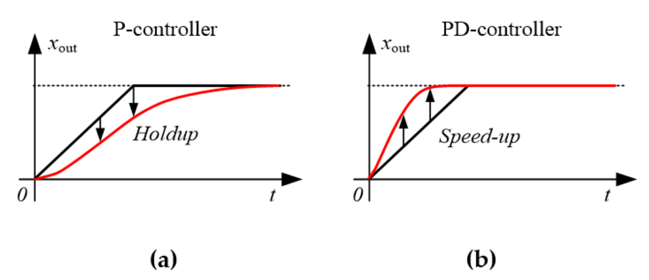
To reduce the transverse asymmetry of gauge profile applying a proportional and differential (PD) RAC controller is suggested which, in fact, controls a filtered derivative of the input signal. The reason for selecting such a controller is that the controllers of such a type provide for the formation of control action with the account of both the control error and its change rate.
This conclusion is clarified by time diagrams, given in
Figure 8 [
26]. Solid lines show the signals at the output of a closed loop for controlling the parameter
xout at the linear change of the input signal shown by dashed lines. The dynamic control error, and output signal delay in relation to the input signal, occurs in the system of automatic controlling with a proportional controller (
Figure 8a) On the contrary, in the system with a PD controller (
Figure 8b), the output signal surpasses the task signal by the acceleration value. This is possible due to control on the input signal derivative.
When setting controller parameters, one should take into account two conditions:
amplification factor (proportional part) should be equal to 1 to fully compensate misalignment;
its differential part should be adjusted for predictive signal tracing, this will make the system response faster;
as clear differentiation leads to the reduction of the system interference resistance, the controller input should have the operating filter.
The transfer function of the PD controller with a filter with a transfer function
is shown in the structure in
Figure 5 as a separate block. The transfer function has the following designations:
p—Laplace operator;
K and
Tf—coefficient of the amplification of the RAC controller and the filter time constant. Also,
Figure 5 shows the time constant of the RAC controller
Td.
The proposed solution is the development of the known principle of predictive control, which is implemented by means of introducing additional connection on the input signal derivative [
27]. In this case the principle was applied in the new technical method for the systems of automatic control of auxiliary mechanisms, linked by the metal strip, of the reversing stand at the heavy-plate rolling mill.
PD controllers, which are a subset of PID controllers, are difficult to synthesize, as the authors [
28,
29,
30,
31] underline. PD RAC synthesis herein was adjusted for the fact that formula-calculated parameters do not provide an optimal configuration. The reason is that analytically derived values are based on simplified models of the object. Paper [
32] details the known synthesis methods. Those methods were analyzed by the authors here; as a result, we used a method that combined analytical (manual) calculations and virtual controller synthesis in Matlab. Commissioning electrical systems with the help of virtual models (digital twins) is the topic of the authors’ paper [
33].
The method follows these steps:
First, we used analytical dependencies to find the controller coefficients. This part of the method is based on analytical synthesis in frequency domain [
34,
35,
36].
Synthesis was run in interactive software on a computer temporarily connected to the control circuit. We generated control signals and monitored response to them in order to evaluate the system’s response to a change in control signals or external influences or noise. Rules applied were based on the authors’ experience, theoretical analysis, and numerical experiments:
Next, the computer was disconnected, and the controller parameters were copied to the controller onsite. It was “manually” fine tuned.
These rules only apply if the controller configuration is optimal or near-optimal. Going farther from the optimal domain may cancel the effects.
4.3. Simulation Model Structure
Mathematical modeling is a reasonable way to test the feasibility of this proposed roll gap misalignment compensation method. To that end, the authors developed a model that simulates automatic control of hydraulic SD positions (DS and OS) and is adjusted for how these positions are linked by the metal strip.
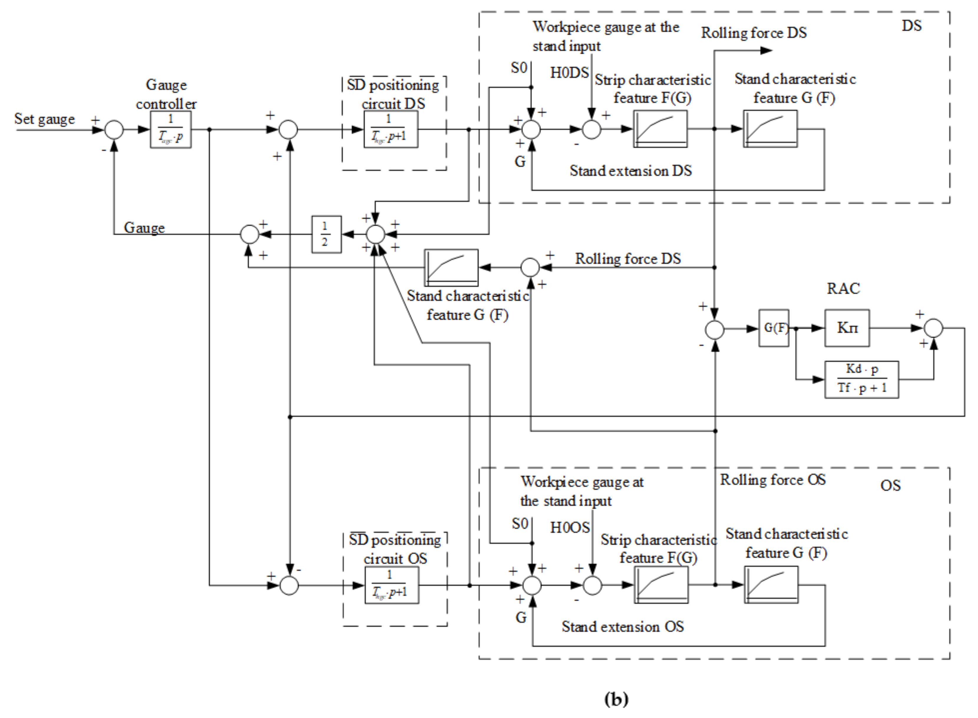
Figure 9a shows the flowchart of the model. It corresponds to the structure of SD positioning as shown in
Figure 5.
Figure 9b shows the flowchart that explains how the AGCS is linked to the SD position controls. The models are implemented in Matlab Simulink.
Strip-mediated SD links are modeled by the non-linear blocks
G(
F). They compute the elastic modulus of the stand as a function of the rolling force. The blocks are part of the DS/OS SD positioning channels as shown in
Figure 9b. Moreover, the structure includes the blocks that simulate
F(
G) the feed stiffness. Both dependencies were derived experimentally and are stored in table format in the controller memory; they are adjusted when calibrating (setting the gap of) the rolls upon their replacement.
The flowchart in
Figure 10b includes the RAC controller. It takes the difference in rolling force between DS and OS as the input and generates additional control signals fed to the SD positioning circuits as the output. These circuits receive the main signal from the gauge controller output. The model shows an integral gauge controller even though the AGCS uses a non-linear one [
15,
37]. This simplification is acceptable, as the RAC controller uses small movements to align misaligned gaps. This is why the non-linearity of the control object does not have a noticeable impact on the tested processes.
The presented simulation model is based on the known structures of electric and hydraulic drives, which are detailed in literature. Some can be found in Matlab libraries. A detailed description of the mathematical model of the object is left out for space considerations; another paper could be written solely on such a model. Such a model should incorporate mathematical models of: automatic electric drives installed in stands; hydraulic screwdowns; automatic parameter controls systems that implement the ROLL-GAP CONTROL concept. They also need to be adjusted for how the strip connects different components. The authors’ papers [
38,
39,
40] detail parts of the model.
5. Results
5.1. RAC Performance Tests
The research team simulated roll gap misalignment control as provided by the proportional RAC controller (the design version), see
Figure 10a for the results. These transients were obtained by testing the disturbance stemming from the variation in gauge between different sides of the feed.
The disturbance in
Figure 10a is the signal
h0DS that sets the feed gauge at the entrance to the stand on the driving side. It is a response to a signal jump in the input of the external AGCS circuit (not shown in the
Figure 10a). At time
t1 = 5 s,
h0DS signals a 2 mm increase in the gauge, which starts a transient. As a result, DS-OS gauge begins to differ, i.e., a wedge emerges as shown in Panel 4; the gauge
hDS at the stand exit increases, see Panel 1. The disturbance causes an increase in the force
FDS (Panel 2), which triggers a nearly simultaneous increase in the signal of the RAC controller, Panel 3.
Signal ΔS of the gauge difference between the sides, Panel 4, is within a 5% window of deviation from the steady-state value by the time t2 ≈ 5.15 s. Thus, the transient associated with this disturbance lasts 0.15 s, which is not acceptable. The key requirement to the RAC controller is to eliminate the misalignment ΔS in the shortest possible time. Thus, in order to improve its performance, the research team decided to reconfigure RAC by their developed method.
Figure 10b shows the transients of coordinates similar to
Figure 10a as produced by simulating the proportional RAC controller above with a positive feedback. Data suggests more intensive processes <1 s before the 5% zone is reached. Thus, the performance of processing a disturbance is >1.5 times better compared to
Figure 10a.
Notably, the curve of gauge difference in Panel 4 enters the negative range. This indicates a short ‘reverse’ roll gap misalignment, which has a positive effect in terms of correcting the feed bending. Should the feed shift off the rolling axis horizontally, additional force will be applied to bring it back to the rolling plane.
The absolute value of the bending can be indirectly found as the area bounded by the curve Δ
S. It is computable as an integral of the dependencies shown in Panels 4,
Figure 10a,b. Calculations show the ‘integral’ to be less in
Figure 10b than in
Figure 10a by a factor of 2.5. This indirectly proves the curbing of camber, which is the goal of this R&D project.
5.2. Roll Gap Asymmetry Adjustment during Rolling
Figure 11 shows the results of rolling simulation featuring the developed roll gap misalignment compensation method and the proposed RAC configuration. At the time
t1 = 4 s, rolls grip the strip. Rolling forces
FDS and
FOS (Panel 2) increase from 0 to 30 MN. At the time
t2 = 5 s, the system begins to process the 2 mm increase in the DS gauge (not shown in
Figure 11). This causes forces in the hydraulic cylinders in Panel 2 to deviate and raises the RAC output
URAC (Panel 3) whereas the gauge controller output
UPT remains virtually constant. These signals control the inputs of SD position controllers, hence they are given in mm. As a result, signals fed to the servo valves (Panel 4) change, and mismatch is compensated by adjusting the hydraulic cylinder pressure.
The presented dependencies lead to a conclusion that the proposed solutions compensate roll gap misalignment with a satisfactory precision. Rapid adjustment of hydraulic cylinder pressure (Panel 2) helps maintain DS and OS gauge precisely. There is no variation in thickness across the feed over the entire passage. The dependencies hOS and hDS in Panel 1 confirm that. The pressure FDS rises by 33% (30 to 40 MN), whereas FOS drops from 30 to 25 MN.
Figure 12 shows similar dependencies derived by running an actual passage with electric drive acceleration and deceleration. The strip is gripped at the time
t1, then at the time
t2 the system begins to process the 2 mm increase in the DS gauge as shown in
Figure 11. The system processes this disturbance until the time
t3, when the electric drive decelerates. The goal of such simulation is to evaluate the precision of misalignment compensation as affected by dynamic acceleration and deceleration of the main electric drives that actuate the upper roll and the lower roll (UMD, LMD).
In both figures, FDS and FOS are proportionally controlled with opposite signs. Thus, the total rolling force FΣ remains constant.
Forces reach steady-state values in one second in the timeframe t2–t3 from 5 s to 6 s in both figures.
Since change in the drive speeds does not affect the rolling force, roll gap misalignment is adjusted precisely in both steady state and dynamic operation. This is shown by side-specific gauge curves
hOS and
hDS in Panel 1,
Figure 11, which are fully aligned.
Applying relatively slow change in the forces
FDS,
FOS (Panel 3 in
Figure 12) does not affect the drive speeds and torques in Panels 1 and 2.
Thus, the hydraulic SDs on the DS and OS do not affect each other. Moreover, SD movements do not affect speed drives due to relatively slow change in the rolling force. Their influence is effectively countered by the fast-response speed control system. Rolling speeds (accelerations and decelerations) do not produce feedback that could affect the precision of SD positioning.
5.3. Experimental Studies
To assess the veracity of the results obtained, the authors conducted experimental studies of rolling the workpieces of various gauges at Mill 5000. The developed method of predictive control of roll gap is technically implemented by the algorithm of control over SD of the reversing stand. Also, the PD RAC controller is introduced.
Figure 13 shows the oscillograph records obtained at the changes made and similar to those given in
Figure 6. They are registered at the rolling of the same profile, and that is why the gauge on the passages (window 1) and the set rolling forces (window 2) on
Figure 6 and
Figure 13 coincide.
When there is torque mismatch occurring in both passages (window 2), the signal at the RAC controller output (window 3) goes down, however, in contrast to the oscillograph records in
Figure 6, the latter does not reach the limitation level. The controlling actions are delivered simultaneously for both hydraulic cylinders. This is confirmed by gap deviations on DS and OS in opposite directions in relation to the set value (window 4). As is clear from the oscillograph records, given in the window 4, the roll gap misalignment Δ
S at the end of rolling in both passages is 1 mm. Similar values, given in
Figure 6, are equal to 2.5 mm. Therefore, one can draw a conclusion that the value Δ
S decreases by 2.5 times as a result of introduction of the developed technical solutions.
5.4. RAC Controller Operation Considered with System of Gauge Automatic Control
In the course of experimental studies the authors conduct the analysis of the interaction of the developed system for roll gap automatic control and AGCS. The purpose is to assess the combined operation of these systems as well as the reasonability of separating their control signals in the frequency range. The research was conducted by means of a passive experiment, and the characteristic oscillograph records are given in
Figure 14. The names of the registered values are provided in windows.
The analysis of the oscillograph records enables the following conclusions:
The signals, received from the automatic gauge control system (AGCS), are high-frequency ones. This confirms an oscillatory nature of a correcting signal at the output of the gauge meter (HPU gap, window 3). This signal tracking induces oscillations in the parameters in windows 4 and 6. Such oscillations are clearly traced at the gauge oscillograph records (window 1) and rolling force oscillograph records (window 5).
The operation of the RAC controller causes misalignment of calibration positions of hydraulic SDs on DS and on OS in the time interval t1–t2 (window 6). It is clear that regardless of SD misalignment on these sides, high-frequency oscillations are traced synchronically. A high-frequency signal from AGDS is superimposed on the signal received from the RAC controller. This confirms the fact that the systems operate in various frequency ranges. This means there are no deviations of controlling actions. Thus, there is no need to separate them in the frequency area, for example, by means switching on band-pass filters.
6. Discussion of the Results
The comparison of oscillograph records given in
Figure 6 and
Figure 13 allows making the following conclusions.
At the proposed setting of the RAC regulator the response of roll gap asymmetry control becomes faster. This is explained by two factors:
the positions of hydraulic SDs in the function of the drive signal derivative are controlled due to the introduction of the controller’s differential part.
the RAC controller does not reach the limitation level, which provides for continuous control during a whole rolling process.
The misalignment of roll gap at the sides DS and OS decreases from 2.5 mm in
Figure 6 to 1 mm in
Figure 13. Obviously, it results in the reduction of gauge difference on feed sides, i.e., in the decrease of its wedging.
Due to the aforementioned positive results, the limitation of horizontal bend and feed axial shift can be provided. In addition, it lowers the risk of occurrence of pre-emergency situations, accompanied by forced roll opening.
Statistical analysis of the cost-effectiveness of this method in production cannot be undertaken easily because roll misalignment due to accidents is rare. It will take a fairly long time to collect statistics on accidents and loss of metal. However, as noted above, accidents may cause the feed to run off the roller table, which has severe implications. Thus, it is both technically desirable and cost-effective to prevent such accidents.
The authors reach an additional conclusion on the results of analysis of
Figure 14. Window 1 shows the oscillograph records of gauge change built on the basis of gauge meter signals. The gauge on the edges and in the sheet center changes by virtually the same. This confirms a satisfactory setting of the RAC controller.
The developed method could be considered simplified, since the rolling force as a function of stand extension on OS and DS is proportional and is calculated by Equation (2). Differential pressure that controls the SD positions is also calculated on the basis of this assumption by Equation (3). More precise dependencies derived from the Golovin–Sims equations are covered in [
5,
6,
41]. They apply to hot-rolling wide-plate roughing mills. Testing their feasibility for adjustment of roll gap misalignment in Mill 5000 and other plate mills is a different problem that requires R&D of its own.
7. Conclusions
As a result of the research the authors obtain the following scientific results:
We specify the concepts on the mutual influence of the parameters of hydraulic screw-down mechanisms, interconnected through the metal strip during rolling. We introduce the notion “differential rolling force”, which is indirectly defined as measured on-line pressure difference in hydraulic cylinders.
We give a rationale and develop the control method for screw-down mechanisms, providing the compensation of the “current” asymmetry of the roll gap due to the compensation of differential force in the hydraulic cylinders of screw-down devices at rolling.
The known principle of predictive control by means of introducing additional connection on the derivative was practically applied in the systems of automatic control of actuating devices at the reversing stand of the heavy-plate rolling mill. The key characteristic feature is the application of this principle for synchronous control over the parameters of the objects, interconnected in the industrial process.
The paper substantiates an idea and presents a newly developed method for predictive adjustment of roll gap misalignment in reverse rolling. The key point of this solution consists in the retention of roll gap on DS and OS at the end of rolling in the straight passage (conventionally, at the rolling forward) and forced setting of the “reverse” roll misalignment before “backward” passage.
The results of testing confirm that the goals of the study, namely better quality of flat products and a less accident-prone process, have been attained.
The feasibility of adopting the developed algorithms is confirmed by simulations and experiments. The experiments also prove the effectiveness of adopting a PD RAC controller.
R&D presented herein essentially furthers the ROLL-GAP CONTROL concept. The ultimate result consists in more precise control over the ‘feed geometry’ and in a less accident-prone process.
In combination with the enhanced systems of axial shift (CVC
plus) and operating roll antibending [
42,
43] as well as with the developed systems of electric drive control [
44,
45,
46], the results obtained have a generalized nature. The research conducted can be also characterized as comprehensive, dedicated to the decrease of gauge variation, enhancement of the profile and flatness of rolled products which are produced at modern heavy-plate rolling mills.


 ,
, 


