1. Introduction
In the global effort to achieve the ambitious targets for decarbonisation of the energy system, at a national and global level, wind energy plays a significant role now and a major one in the future. Thus, the European Union (EU) aims to move to 100% clean energy by 2050 as an important step in achieving climate neutrality, the energy sector being responsible for more than 75% of greenhouse gas emissions (GHG) at the European level, according to the European Green Deal [
1]. This goal can be achieved by using renewable energy sources, a key role being granted to increasing wind production by improving wind energy systems, especially installed offshore. In all decarbonisation scenarios, which consider the high-level implementation of renewable energy systems, it is emphasized that the main source of electricity generation will be wind power by 2050 [
1,
2] with a share of over 36% of the total [
3,
4]. Thus, wind energy had a total installed capacity of 743 GW at the end of 2020 [
5], with an increase to over 6000 GW foreseen by 2050 [
4], as wind power remains an efficient and affordable technology of producing clean electricity in a safe and sustainable way. Energy management considering the variability of renewable energy sources and the reliability of networks and systems facing utility grid outages remains a challenge for energy systems with a high share of renewables [
6,
7,
8].
The wind energy sector is gaining more and more popularity among researchers, developers and investors. They have paid attention to the behaviour of onshore and offshore wind systems and their components in different operating conditions. Their optimal design and modelling are permanent challenges in ensuring the high energy performance of wind systems, operating under variable wind conditions. Therefore, the dynamic behaviour of wind turbines is of significant interest as it influences significantly the conversion system functional performance, output power, and reliability.
The dynamic modelling of wind turbines in order to identify and control their behaviour or their functional optimization has drawn the attention of many researchers in recent decades. The research in this field is addressing either the dynamics of the entire wind turbine/farm or the dynamic modelling of a component of the wind conversion system: wind rotor, speed increaser, or electric generator. Different dynamic modelling approaches are presented in the literature, while the simulation is mainly performed with the MATLAB-Simulink software package.
Cottura et al. present in [
9] the modelling of a floating wind turbine under a broad spectrum of sea and wind conditions. The dynamic model is compared with the FAST reference model (fatigue, aerodynamics, structures, and turbulence), a reference software for modelling offshore wind turbines, the errors between the two models being reported as being below two percent. A similar concept is presented in [
10] where the hydrodynamic performance of the floating foundation of an offshore wind turbine is analysed based on Reynolds-Averaged Navier-Stokes simulations. The FAST dynamic model allows the performance investigation of the floating platform under operational and storm conditions. A rigid multibody dynamic model for a floating offshore wind turbine and its dynamic responses are presented in [
11]. The authors use the Euler–Lagrange equations for system motion, while the dynamic response under four load cases is validated against the FAST model.
The dynamic of the onshore wind systems is addressed as well in the literature, referring mainly to general theoretical models, based on customised models that can be developed. For instance, Santoso and Le present in [
12] a dynamic model that includes aerodynamic, mechanical, and electrical components of a turbine operating at a constant wind speed. The model is simulated in four case studies to prove its validity. Equivalent models of wind farms operating at constant wind speed are proposed in [
13]. These dynamic models offer high accuracy of the dynamic response regarding the simulations of the energy system and a reduction in the simulation time compared to the detailed model of the actual wind farm.
A dynamic model of a fixed-pitch angle wind turbine simulator is presented in [
14], which includes different wind turbine profiles for which the mechanical power characteristics of the wind turbine are assigned. The model allows defining the mechanical power and torque as functions of the wind speed. A similar concept is presented in [
15], where the Blade Element Method is used to determine the power coefficient of a turbine consisting of a wind rotor, a speed increaser, and a conventional electric generator. The model considers the hydrodynamic data for the rotor, the inertia characteristics of the whole system, frictional losses, and the electromagnetic torque of the generator. Qi et al. propose in [
16] a method to improve the dynamic response of a wind turbine by a torque error feed-forward control and the blade-pitch angle servo control. The mechanical system model is based on the FAST code, the results being validated on a five megawatt wind turbine. The dynamic behaviour of wind turbines under stormy wind conditions is presented in [
17]. The authors use the beam theory to couple the wind turbine dynamic model to the unsteady aerodynamic model to generate the dynamic response of the system. The results are simulated on two wind turbines of two and six megawatts. The dynamic model of a wind turbine without a gearbox is presented in [
18], the simulation performed in MATLAB-Simulink considering load flow, fluctuations in wind speed, and transient and output power.
The researchers in the field have paid particular attention to the dynamics of the gearbox, the literature proving that the dynamic behaviour of speed increasers is closely related to the dynamic behaviour of the wind systems. A gear transmission of Ravigneaux type is used in [
19] to propose a dynamic analysis method based on a general algorithm for determining the transmission ratio, transmission torques, and efficiency. Another method for dynamic modelling uses numerical integration of Runge-Kutta type [
20], and considers nonlinear dynamic characteristics of a speed increaser with one input and one output. Another nonlinear dynamic model is presented in [
21], which considers a planetary speed increaser with an input and an output for which the load distribution on the gears is studied, the algorithm being based on the lumped parameters method. To improve the load-sharing capacity on the component gear pairs, Zhu et al. present in [
22] a dynamic model of a planetary speed increaser with flexible pins. The dynamic behaviour of the wind system is also studied using the lumped parameter model, in which the stiffness of the bodies is predicted using the finite element method. Another approach is proposed by Fan et al. in [
23] that discusses the dynamics of a speed increaser depending on the power vs. speed curve; the dynamic effect due to different input powers on the mechanical characteristics of the speed increaser is also investigated. A dynamic analysis of a planetary speed increaser is developed in [
24] using the torsional multibody model, used to investigate the transient response of the transmission. Different planetary speed increasers for wind and hydro applications are proposed and dynamically analysed in [
25,
26] as transmissions with one input and one output. A new planetary speed increaser with two inputs and one output is proposed by Lin et al. [
27] and its dynamic responses are simulated using the fourth order Runge-Kutta method. The time-domain dynamic response of heavy-duty planetary speed increasers is studied in [
28] by using the lateral–torsional coupling modelling method; the method is validated on a two megawatt wind turbine gearbox. Wang et al. developed in [
29] a dynamic model for a multistage planetary gear transmission by using the lumped parameter method to obtain the load-sharing coefficients for each planet gear pair under variable input speed and internal excitation.
Unlike the previously presented results that refer to gear transmissions used as speed increasers, ref. [
30] proposes a new variant of a cycloidal planetary transmission for renewable energy systems and analyses its dynamic behaviour, the efficiency values being experimentally validated.
A general approach to the steady-state efficiency analysis of speed increasers with both one or two inputs and one or two outputs is proposed in [
31]. The authors concluded that the in-parallel or split-power transmissions used in wind turbines with either two counter-rotating rotors or a counter-rotating generator have higher efficiency than serial transmissions.
Another approach in dynamic modelling is the use of controllers adapted for wind turbines with a double-fed induction generator, which allows the estimation in real time of dynamic behaviour compensating for the external disturbances action [
32]. The optimal design of proportional-integral controllers integrated in on-grid permanent magnet synchronous generators from variable-speed wind turbines is addressed by Qais et al. in [
33] by proposing a transient search optimization algorithm.
Aiming to improve the performance of the electric generators for wind turbines, a counter-rotating generator with permanent magnets for built environment applications is proposed and analysed in [
34,
35,
36]; the counter-rotating generator is proved to have a higher efficiency than the conventional one, with a low starting torque, it is compact and scalable.
The literature survey concludes that the dynamic behaviour is performed only for systems with one input and one output or two inputs and one output, i.e., wind turbines with a conventional electric generator. In the vast majority of the presented research, the wind rotor and generator have nonlinear models, which lead to a dynamic model with a high complexity. In addition, some onshore theoretical models consider the wind turbines operating under constant wind speed. Generally, the numerical simulations are performed on high-power wind systems using Matlab-Simulink. As a result, the authors did not identify in the literature relevant results regarding the generalized dynamic modelling of the mechanical system for the class of wind turbines with single wind rotor and a counter-rotating electric generator, which would enable obtaining, in a simpler way, the dynamic response under variable wind speed.
The paper aims to cover the gap by proposing a novel algorithm for dynamic modelling of single-rotor wind systems that include a counter-rotating electric generator and a speed increaser with one input (connection to the wind rotor) and two outputs (connections to the rotor and stator of the electric generator), meant also to be used in real very attracting low-power applications, e.g., in the built environment. The power generated by the wind rotor is branched to the generator rotor and stator, a solution that brings several advantages compared to the conventional wind turbines (with fixed stator): higher mechanical efficiencies, a more compact speed increaser (with lower kinematic ratio), and a self-balancing electric generator in operation. The dynamic modelling is performed under variable wind conditions. It combines the classical equations associated with the rigid bodies with fixed-axis rotational motion (mechanical moments of inertia, kinematic transmission ratios, and the efficiency of the cylindrical gear set) with the linear equations associated with the mechanical characteristics for both the direct current (DC) generator and the wind rotor, respectively, on its quasilinear active working sector in operation. The linear equations of the wind rotor mechanical characteristic are expressed as functions of wind speed. The motion and efficiency equations in the dynamic regime are defined analytically and simulated for the case study of a 10 kW wind turbine, the numerical results validating the generalized theoretical model.
The paper is organised as follows:
Section 2 presents the configuration of the wind turbine with counter-rotating generator and the analytical model for angular speeds and kinematic ratio;
Section 3 is devoted to the dynamic analytical modelling; in
Section 4 the numerical simulations and analyses are performed for a specific scenario; and
Section 5 provides the conclusions.
2. Problem Formulation
Wind turbines with counter-rotating electric generator are characterised by a mechanical system with higher inertia versus the ones with conventional electric generator, due to the rotation of the generator stator, which usually is characterised by a higher mechanical moment of inertia than the generator rotor. Therefore, identifying the transient dynamic behaviour of these wind turbines when changing the wind speed is a challenge in expanding the implementation of wind turbine solutions with counter-rotating electric generators and also for their better operation.
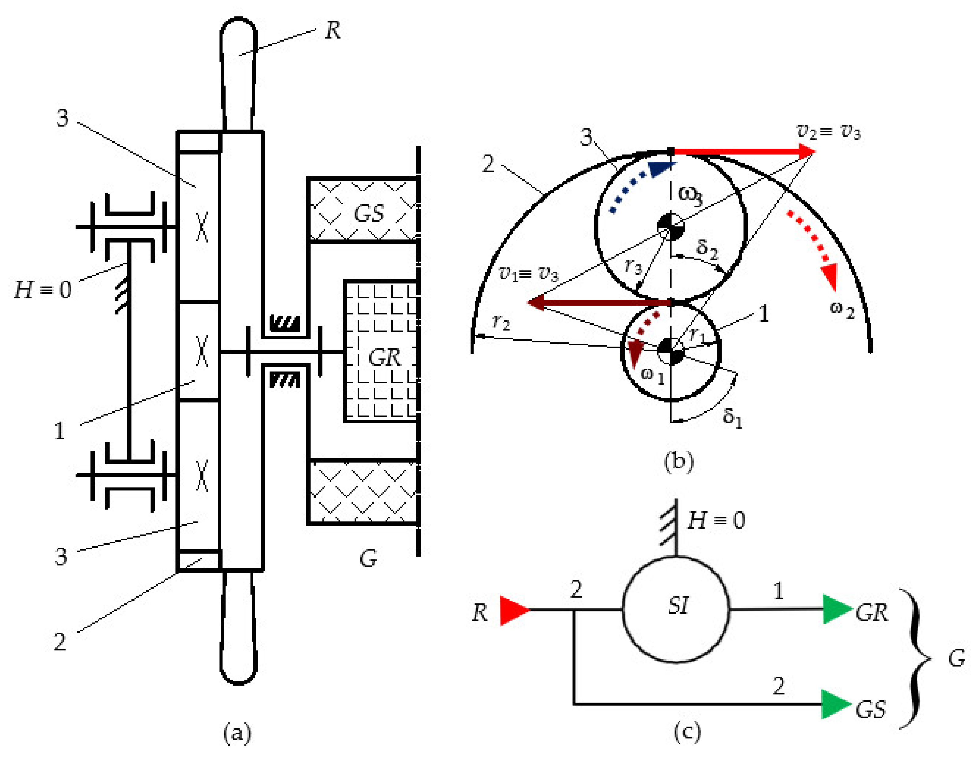
The modelling of the dynamic response of wind turbines with counter-rotating electric generator was further developed for a generic wind turbine including a simple gearbox. The analysed wind turbine consisted of a wind rotor
R, a fixed axes speed increaser
SI with one input and two outputs, and a counter-rotating electric generator
G, characterised by the rotation of the rotor
GR and stator
GS in opposite directions,
Figure 1.
The speed increaser
SI was derived from a cylindrical planetary gear set with one satellite gear, which functioned as a fixed axes mechanism obtained by connecting the satellite carrier
H to frame 0. Thus, the mechanical power input in the speed increaser was achieved through a ring gear 2, which was connected to the wind rotor
R and to the generator stator
GS, which engaged with two or more evenly distributed gears 3. The gears 3 engaged simultaneously with gear 1, which ensured the transmission of mechanical power to the generator rotor
GR. The ring gear 2 and gear 1 had the same revolute axis, namely the
central axis. As a result, the input mechanical power was distributed on two branches to (
Figure 1c):
- -
the generator rotor GR, through the speed increaser SI, with speed amplification;
- -
the generator stator GS, without changing the input speed due to the direct connection between the wind rotor R and the stator GS.
The angular speeds of the gears and the kinematic ratios, under the conditions of the branched transmission of mechanical power from the input 2 ≡
R to the outputs 1 ≡
GR and 2 ≡
GS, can be obtained based on the scheme from
Figure 1b:
where
is the angular speed of gear
x = 1…3;
—the peripheral linear speed on the pitch circle of radius
of gear
x = 1…3;
—the angle between the straight lines given by the center of rotation of gears 1, 2 and the origin and the tip, respectively, of the speed vector
;
—the teeth number of the gears 1, 2;
—the kinematic ratio (i.e., the ratio of angular speeds) when the rotation motion is transmitted from body
x to body
y.
In the operation of an electric generator, the relative angular speed of the rotor to the stator ω
G (referred to as the angular speed of the electric generator) is a characteristic parameter for the generated electric power:
As a result, the total amplification ratio of the angular speed
achieved by the wind turbine with counter-rotating generator can be determined with the following relation:
The dynamic modelling of the wind turbine from
Figure 1 was performed under the following premises:
- -
the moving components (gears, the wind rotor, the rotor and stator of the electric generator) were rigid bodies with the mass distributed evenly and, also, geometrically symmetrical in relation to their own axis of rotation; therefore, the centre of mass of a body was a fixed point, located on the body fixed axis of rotation;
- -
only the frictional losses in the gearing were further considered, while the frictions in the revolute joints, materialised by bearings with low friction coefficients (due to the rolling friction), were neglected;
- -
the wind rotor and the electric generator were not adjusted during operation, which means that the pitch angle of the blades did not change in operation, and the adjustment parameters of the electric generator remained constant in operation;
- -
the wind rotor and the electric generator had known mechanical characteristics of linear type with constant coefficients. The mechanical characteristic of a wind rotor is a complex 2D curve, which can be approximated with a linear function in the steady-state regime. Moreover, the DC generators are characterised by a linear dependence between the driving torque and the angular speed of the electric generator ωG;
- -
the electrical losses inside the generator were neglected in this study.
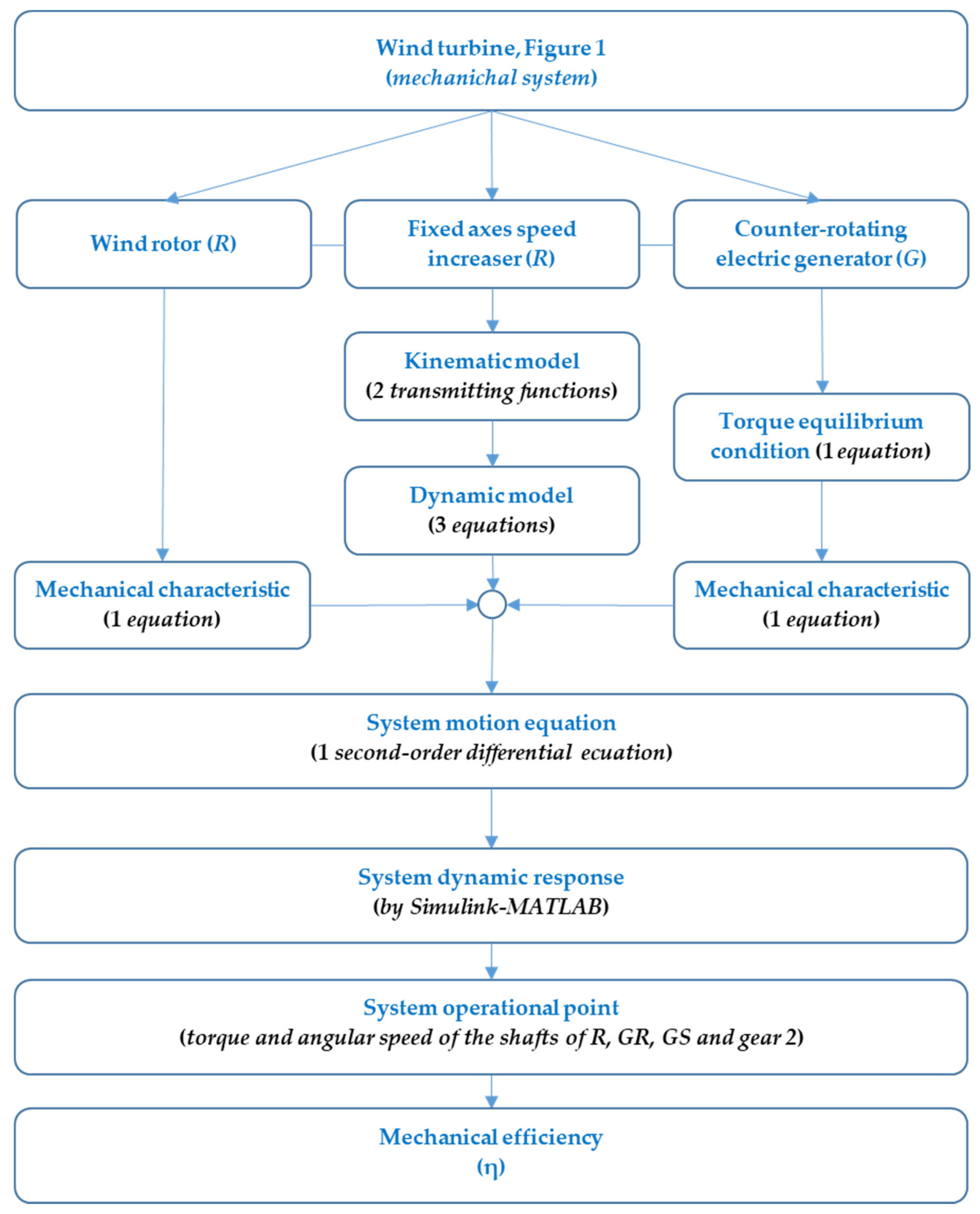
The main stages of the proposed dynamic response modelling of the wind turbine mechanical system are depicted in
Figure 2 and further presented. Based on the conceptual diagram from
Figure 1, the input parameters in this algorithm were the wind rotor radius, efficiencies of gear pairs and teeth numbers of the gears from the speed increaser, the torque-speed characteristic of the electric generator, and the inertial properties of the components. In the first stage, the kinematic modelling of the wind turbine mechanical system was performed by obtaining the transmitting functions for the angular speeds and the other angular speeds that are dependent on the independent speed of the wind rotor. For this mechanical system, three dynamic equations can be described, corresponding to the three rigid bodies to which the mechanical transmission can be reduced. The dynamic equations can be obtained by various approaches, in this case by using the Newton-Euler method. The mechanical characteristics (torque-angular speed dependence at a shaft level) of the wind rotor and the electric generator were added to the kinematic and dynamic equations of the mechanical system. This study considered the case of DC electric generators, characterized by linear characteristics modelled by linear functions, as well as by the equality in absolute value of the torques on its rotor and stator, both mobile with rotations in opposite directions. The mechanical characteristic of the wind rotor can be linearized on the active operating area, the coefficients of the linear function being dependent on the wind speed. These equations enable the calculation of the differential motion equation of the system that describes the behaviour in transient and steady-state regimes depending on the independent kinematic variable (the motion of the wind rotor).
The motion equation can be solved by using Simulink-Matlab software and obtains the system dynamic response (i.e., variation over time of the parameters of independent motion). Once the dynamic response is established, all the other kinematic parameters and torques that are associated with the mechanical transmission shafts are obtained explicitly based on the previous set of equations, including highlighting the changes in mechanical efficiency during wind turbine operation. The proposed algorithm is a general one and can be applied to any wind turbine with a single wind rotor and a counter-rotating electric generator, regardless of whether the mechanical characteristic of the wind rotor is linearized or not, the speed increaser has fixed axes or is of planetary type, and the generator is either a DC or an AC. For the sake of simplicity and better understanding, the simplified case of fixed axes speed increaser and linear mechanical characteristics is considered in this paper.
3. Dynamic Modelling
The dynamic equations of a general system of motor(s)-mechanism-effector(s) type describe the system motion under the action of actuation and resistance forces/torques. The dynamic equations of a wind turbine under the premises mentioned in
Section 2 are homogeneous linear differential equations of second order. The angular acceleration and speed of the wind rotor interfere with and define the independent motion of the mechanical system.
The dynamic modelling method uses the equations of the Newton-Euler formalism and implies the prior isolation of each body by replacing the connections between the bodies by the corresponding reaction forces. It is followed by the description of the Newton-Euler equations for each body, according to the general expression when the origin of the coordinate system attached to the body coincides with the body centre of mass cm [
37]:
where
F is the resultant force vector acting on the centre of mass,
m—the body mass,
I3—the 3 × 3 identity matrix,
acm—acceleration vector of the centre of mass,
T—resultant torque vector acting on the centre of mass,
Jcm—moment of inertia defined about the centre of mass,
ω—angular speed vector of the body, and
ε—angular acceleration vector of the body.
In the case of symmetrical bodies with a fixed axis of rotation (i.e., the centre of mass cm is a fixed point on the axis of rotation), Equation (7) can be simplified in the following scalar form:
where
T is the resultant torque acting on body,
J—moment of inertia around the body motion axis, and ε—angular acceleration of the body.
3.1. Dynamic Equations of Component Bodies
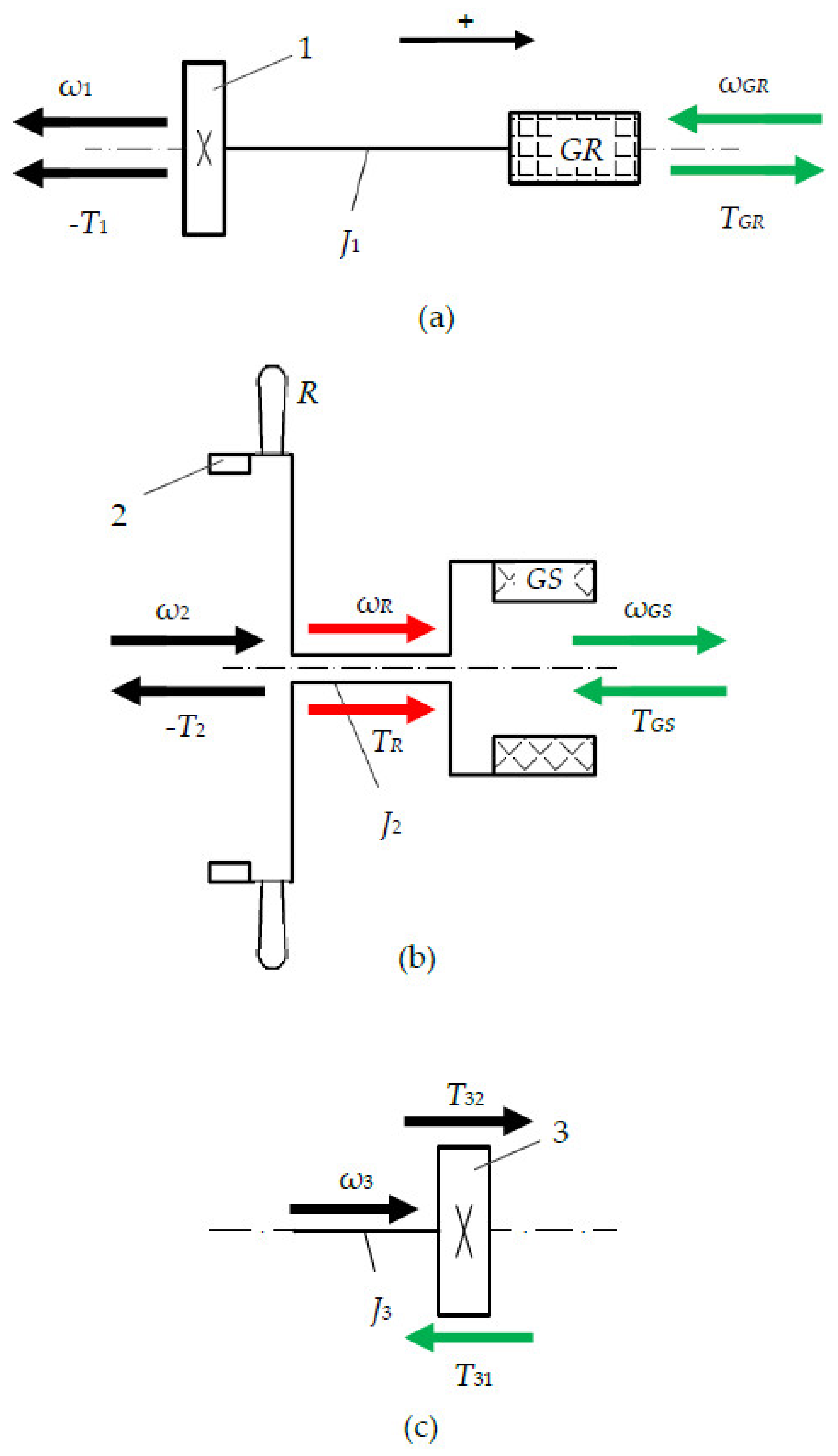
Based on the scheme from
Figure 1a, the considered wind turbine can be decomposed into the following rigid bodies:
- -
body B1: the assembly consisting of the sun gear 1, the generator rotor
GR, and the connecting shaft,
Figure 3a;
- -
body B2: the assembly wind rotor
R—ring gear 2—generator stator
GS,
Figure 3b;
- -
a number s
3 of gears 3 and their shafts (body B3), evenly distributed around the central axis,
Figure 3c.
The positive direction of the angular speed and torque vectors for all the bodies B1… B3 is defined to the right (
Figure 1), while
Jx denotes the axial moment of inertia of the body x = 1… 3,
—the angular speed of the body
x, and
—the resultant torque acting on the body
x.
Thus, considering the body B1 characterised by the fixed-rigid connection between gear 1 and the generator rotor
RG, the following equations can be written (
Figure 3a):
Similarly, the kinematic and dynamic equations of the B2 body, characterised by the connections
, can be described by (
Figure 3b):
The mechanical power is transmitted from ring gear 2 to gear 1 through s
3 theoretically equal flows, corresponding to s
3 number of gears 3 that are mounted in parallel between gears 2 and 1. As a result, the body B3 is driven theoretically by a torque
T32 defined by relation (13):
which comes from the energetic equilibrium equation with friction for the gear pair 2–3:
where
is the kinematic ratio of the gear pair 2–3, and
—the efficiency of the gear pair 2–3.
Gear 3 is also subjected to a reaction torque
T31 from gear 1:
defined as well based on the energetic equilibrium equation with friction for the gear pair 3–1:
where
is the kinematic ratio of the gear pair 1–3, and
—the efficiency of the gear pair 3–1.
As a result, the dynamic equation for the body B3 is:
which by considering Equations (13) and (15) becomes:
Relation (18) models the transmission of mechanical power from gear 2 to gear 1 in the general case of considering the inertial effects of the body B3 and the impact of gear friction; if the mass of body 3 is neglected (i.e.,
) or if the turbine is operating in a steady-state regime (i.e.,
), Equation (18) takes the particular form:
which expresses the energetic equilibrium condition of the speed increaser
SI in the premise of considering friction in gear pairs, in which:
and
3.2. Mechanical Characteristics
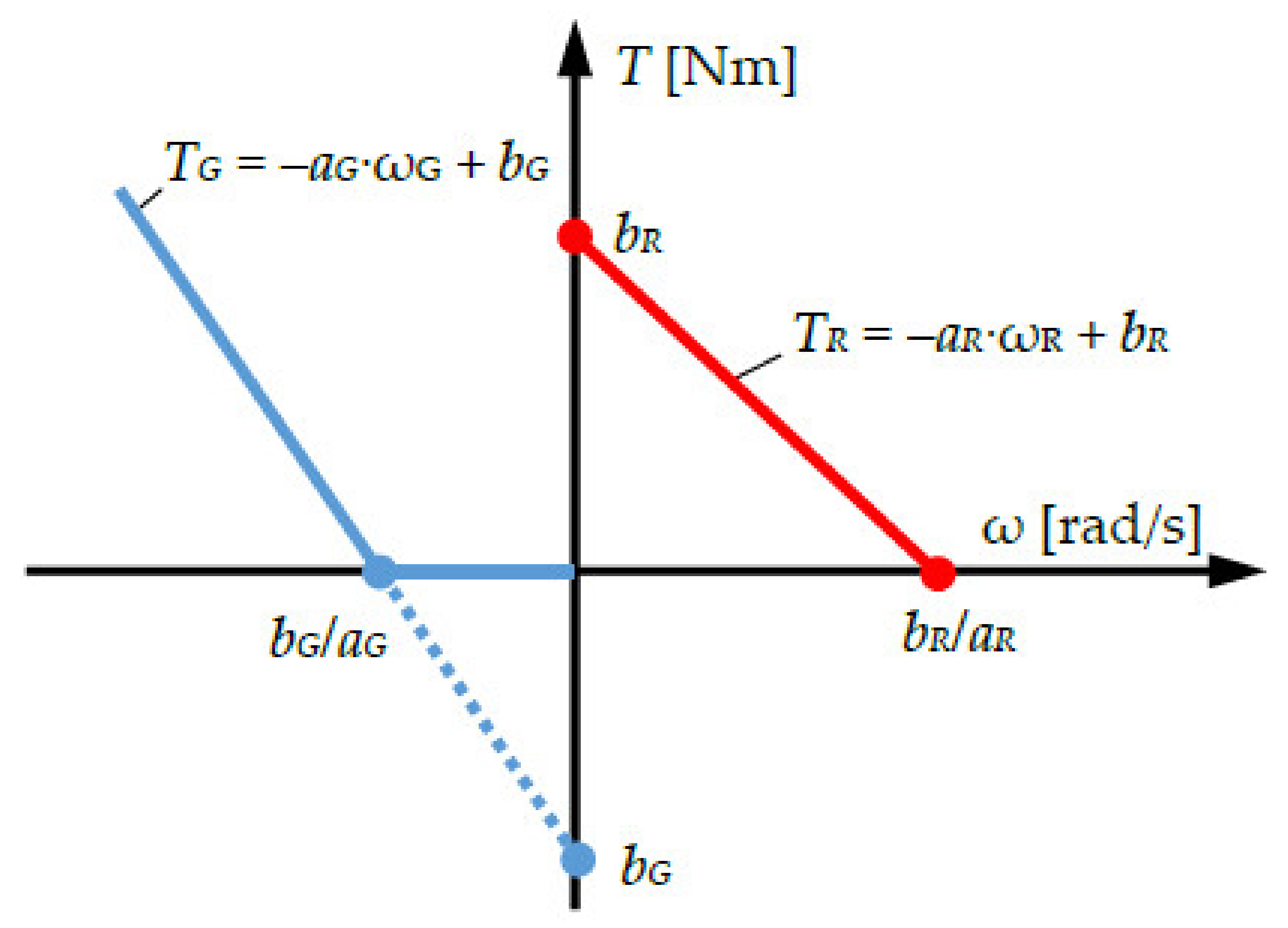
The set of dynamic equations of the three bodies B1…B3 is completed with the linear mechanical characteristics with constant coefficients of the wind rotor and the counter-rotating electric generator, respectively:
- -
the electric generator G
where
are the constant coefficients under the steady-state regime, and, by definition,
TG =
TGR. Moreover, the functional specificity of an electric generator ensures the torque equilibrium condition between the rotor
GR and the stator
GS:
According to the chosen positive direction (see
Figure 3), the mechanical characteristic of the wind rotor is active in quadrant I (
TR > 0 and ω
R > 0), while for the electric generator in quadrant II, (
TG > 0 and ω
G < 0) for absolute values of the angular speed ω
G larger than the critical value
, which delimits the operating modes as motor and generator of the
DC machine,
Figure 4. Therefore, in the dynamic analysis, the electric machine will be considered in idle functioning regime (i.e.,
TG = 0) until the required operating speed as a generator is reached:
In the present study, it was assumed that the electric generator was not adjusted during operation, and the pitch angle of the wind rotor blades was not changed. Instead, the mechanical characteristic of the wind rotor changes with the variation of the wind speed, as the mechanical power
PR generated at the wind rotor shaft depends on wind speed value [
38]:
where ρ is the air density,
Cp—aerodynamic power coefficient,
rR—radius of the wind rotor, and
vw—the wind speed.
In the general case, the coefficient
Cp depends on the wind speed
vw, the angular speed of the wind rotor ω
R, and the blade pitch angle β. Since, in this study, the pitch angle was considered constant β = 0°, the general relation of the power coefficient
Cp [
38,
39,
40] is obtained through particularisation in the following form:
where λ is the tip speed ratio:
and
where
c1 = 0.5176,
c2 = 116,
c3 = 5,
c4 = 21,
c5 = 0.0068, and
c6 = 0.035.
Thus, the mechanical characteristic of a wind rotor
can be described analytically by Equation (30):
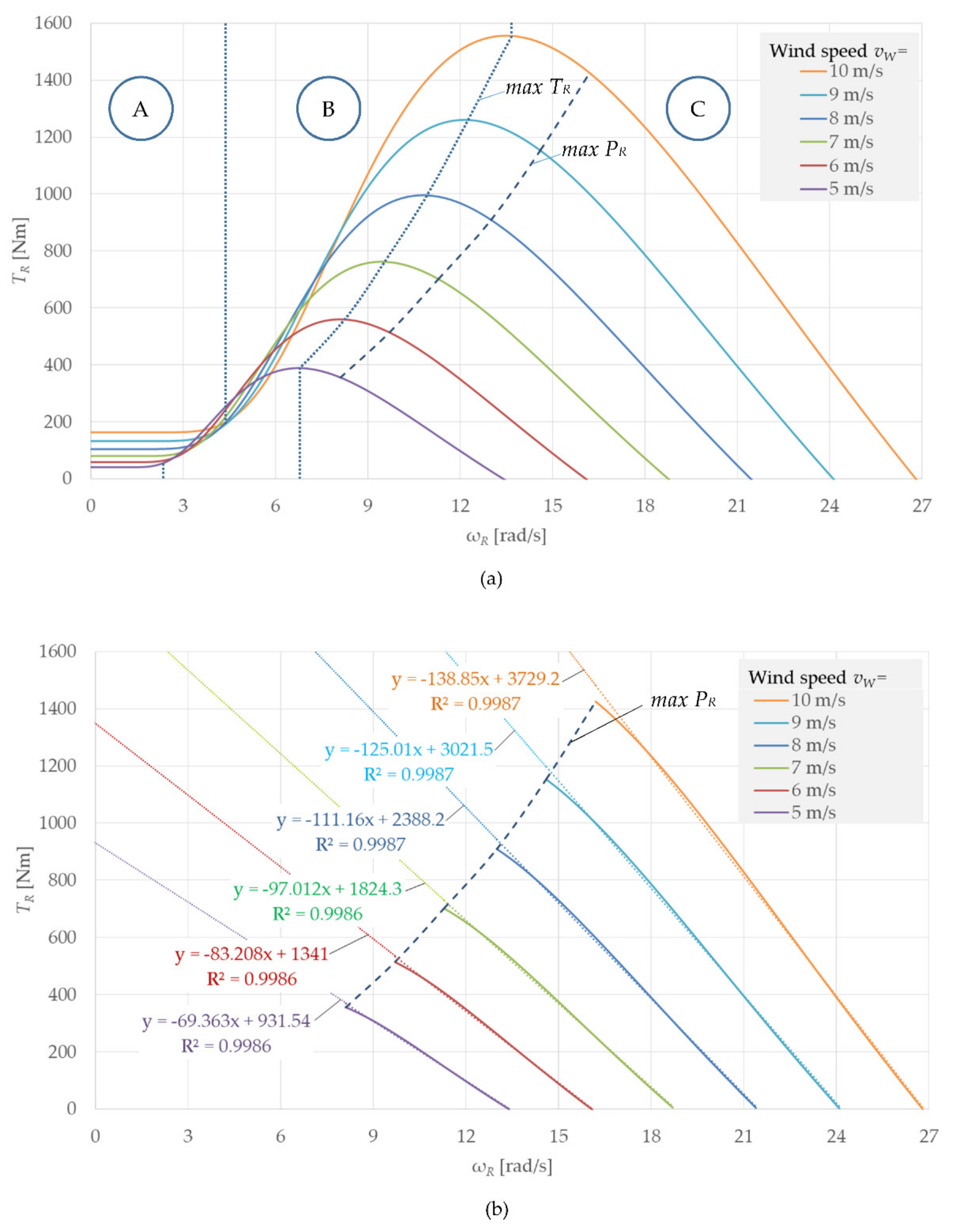
Considering the air density ρ = 1.225 kg/m
3, the mechanical characteristic of a wind rotor with the radius
rR = 5 m is illustrated in
Figure 5 for different values of wind speed
vw. There is a distinct evolution of the torque
TR on the three zones A, B and C (
Figure 5a), with approximately linear shapes, rounded at the transition from one zone to another. Thus, the torque
TR remains constant with the increase in the angular velocity ω
R up to a threshold value of the angular speed (which increases with the increase in the wind speed, zone A), followed by an ascending evolution to the maximum value (
max TR, zone B) and a lower slope decrease on zone C—the normal operating area of the wind rotor. It can also be noticed that the maximum power points (
max PR) are found in zone C, at higher values of the angular speed ω
R than those corresponding to the maximum torque points (
max TR). Moreover, regardless of wind speed, the maximum power points are located at the limit of the approximately linear sector of the mechanical characteristic from zone C. Therefore, it is reasonable to consider the hypothesis of mechanical characteristics of wind turbines as linear functions with constant coefficients at a given value of the wind speed, under the condition that the wind turbine operates at optimal angular speed values (corresponding to the maximum power point) or higher.
Considering the curves in zone C approximated by linear functions, described according to Equation (22), the influence of increasing wind speed on the wind rotor mechanical characteristic can be summarised as follows (
Figure 5b):
it causes the increase in the angular speed during idle operation (i.e, TR = 0), meaning the increase in the bR/aR value.
it leads to the increase in the characteristic slope and to the increase in the bR value, implicitly.
As a result, both coefficients aR and bR are directly influenced by the wind speed and thus the wind rotor operates under a different mechanical characteristic when the wind changes its speed.
3.3. System Motion Equation
The wind system motion in the dynamic regime is described by a second-order differential equation represented as a function of the independent input motion of the wind rotor R, i.e., the angular speed and angular acceleration , where is the angular displacement of the wind rotor, and .
According to Equations (10) and (18), the torques
T1 and
T2 are obtained:
and considering Equations (11), (12), and (31), the angular acceleration is obtained:
in which the following obvious replacements are considered:
Equation (35) is obtained from Equations (23), (5), and (11):
The motion equation of the wind system is obtained replacing Equations (22) and (35) in (33):
The following a priori known constant parameters interfere in the differential Equation (36):
in which the parameters
and
are dependent on the wind speed, according to linear trend lines in
Figure 5b.
The time variation of the independent parameters (
,
,
) is obtained solving Equation (36) under given initial conditions, which describes the evolution in time of the kinematic (displacements, angular speeds, and accelerations) and dynamic behaviour (torques, powers, and efficiency) of the wind system and its components. Equation (36) is numerically solved using Simulink-MATLAB by MathWorks, aspects of which are presented in
Section 4.
3.4. Mechanical Efficiency
The energy loss due to friction in a mechanical system is expressed by mechanical efficiency, as a measure of how the mechanical input power is transmitted through the mechanism to the outputs. The mechanical efficiency is a variable quantity in the transient regime, significantly influenced by the system’s inertial properties, which tends asymptotically towards a maximum value specific to the steady-state system operation.
Thus, the relation for the mechanical efficiency of the wind turbine is established starting from its definition, in which Equations (22) and (35) are replaced:
Equation (36) is solved as a function of
and the mechanical efficiency in the transient regime is obtained after the replacement of the obtained solution in Equation (38):
where
J* is the equivalent mechanical moment of inertia of the system reduced at body 2:
Equation (39) shows the dependence of efficiency on the angular acceleration
of the wind rotor; in a steady-state regime (i.e.,
), the expression of the mechanical efficiency can be simplified as follows:
Unlike the conventional wind turbines with a wind rotor and conventional generator (with fixed stator), in which the speed increaser has the efficiency independent of the speed amplification ratio, the stationary mechanical efficiency of wind turbines with counter-rotating generator depends on both the efficiency of the speed increaser SI with fixed axes (i.e., ) and the kinematic ratio , according to Equation (41). Given that the kinematic ratio has a negative supraunitary value and , it is obvious that . Thus, it can be concluded that wind turbines with counter-rotating generator have a better mechanical efficiency in a steady-state regime than the conventional systems that integrate the same speed increaser.
4. Results and Discussions
The numerical simulations of the dynamic model presented in
Section 3, developed for the wind turbine with counter-rotating electric generator described in
Section 2, aim to highlight the evolution in time of the mechanical power parameters (i.e., torque and angular speed) for input and output shafts, as well as the angular acceleration and the system mechanical efficiency, in the conditions of sudden changes of the wind speed. Thus, we considered a wind turbine with a rated power of 10 kW at a nominal wind speed of 8 m/s, characterised by the parameters from
Table 1, in a operating scenario in which the wind turbine started under the action of a 8 m/s wind (stage I), after which the wind speed dropped sharply to 6 m/s after 8 s (stage II) and then returned to 8 m/s after 15 s (stage III). Since the linear model adopted for the mechanical characteristic of the wind rotor is valid only on the useful area of this characteristic (see
Figure 5, zone C), in stage I the initial starting phase was ignored (which is not the object of this research) and the time of 0 s was chosen at the moment when the angular speed of the wind rotor reached the value corresponding to the maximum power
max PR.
The dynamic analytical model of the wind turbine was implemented in the Simulink module from Matlab by MathWorks. The obtained graphical results including the mechanical efficiency of the wind system are systematised in:
Figure 6 for the input (wind rotor
R) and output components (electric generator
G),
Figure 7 for the rotor
GR and the stator
GS of the electric generator, and the distributions of the torque and power of the wind rotor on the two branches towards the speed increaser input and towards the stator
GS are illustrated in
Figure 8.
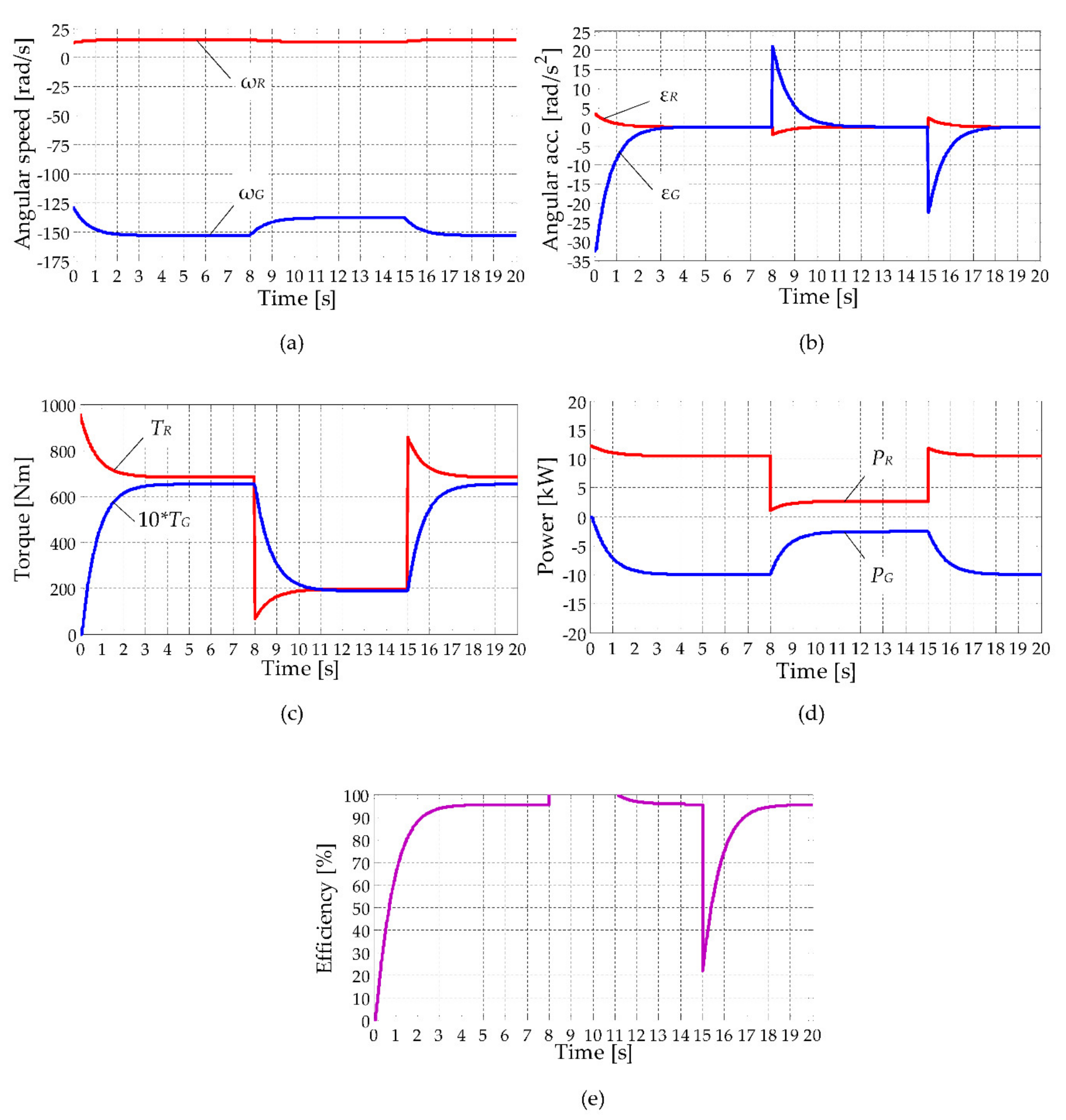
In stage I of the considered operating scenario, the wind turbine passed through a transient period until entering the steady-state, i.e., characterised by constant values of the kinematic parameters and torques,
Figure 6a–d. Typically, the beginning of the steady-state regime is identified when the angular accelerations become null,
Figure 6b. In this transient stage, the system was accelerated, a significant part of the wind rotor power
PR was used to overcome the inertial resistance of the mechanical components and the accumulation of kinetic energy, implicitly.
The electric generator started producing electricity only when the speed
became equal to the value
bG/
aG = 131.67 rad/s (see also
Figure 4), shortly (about 0.1 s) after the entry of the wind rotor into the active area of its mechanical characteristic. At each operating time, the ratio between the angular speeds
and
and the ratio between the angular accelerations
and
, respectively, was constant and equal in this case to
iG_R = −10.
In the steady-state operating regime during 4 to 8 s, the electric generator was operated with a power of 10 kW (
Figure 6d) at an angular speed = 153.4 rad/s (
Figure 6d).
The decrease in the wind speed to 6 m/s after 8 s of operation (Stage II) caused the change in the mechanical characteristic of the wind rotor (see
Table 1) and also the crossing of a transient stage (of about 3 s) towards a new steady-state operation,
Figure 6a–d. The significant decrease in the wind rotor power
PR to ~2.67 kW and of the driving power of the electric generator
PG to ~2.56 kW, i.e., a reduction of ~25% of the rated power when the wind speed has dropped to only 75% of its nominal value, is noted in
Figure 6d. This significant decrease in power is due mainly to the large decrease in torques (
Figure 6c) and less of the angular speeds (
Figure 6a).
It is also worth noting the atypical evolution of the mechanical efficiency η, which became supraunitary under the conditions of the definition from Equation (37): according to
Figure 6d, the power of the wind rotor
PR decreased suddenly with the decrease in the wind speed, but the power
PG changed progressively due to the active effect of the kinetic energy, accumulated in the previous stage, which was added to the mechanical energy produced by the wind rotor. The efficiency η in a steady-state regime was higher than the efficiency of the speed increaser (η
2_1), i.e., 95.53% vs. 95.06%.
In stage III of the numerical simulation scenario, the wind speed returned suddenly to the nominal value
vw = 8 m/s, after 15 s of operation. The variation in the functional parameters was relatively similar to the one from stage II, symmetrically to the horizontal axis. A sudden decrease in efficiency can be noted (
Figure 6e) given that the power of the wind rotor was used at the beginning mainly to accelerate the mechanical system and less to increase the power
PG.
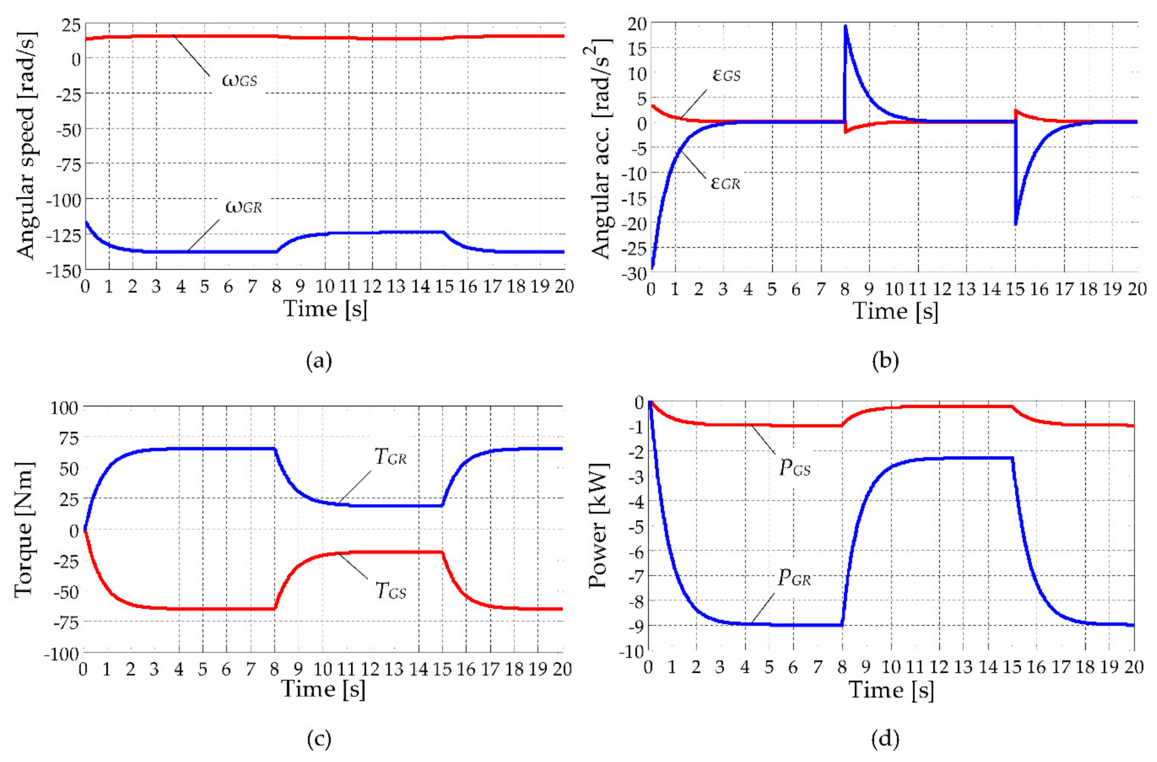
The evolution in time of the kinematic parameters and torques for the two mobile components of the electric generator, in the three stages of the simulation scenario, are presented in
Figure 7. The generator rotor
GR had an angular speed increased by
iGR_R = −9 and higher than speed of the stator
GS, implicitly (
iGS_R = 1),
Figure 6a. The angular accelerations
and
(
Figure 7b) had similar evolutions to those illustrated in
Figure 6b, given that
and
, which are derived from Equations (11) and (5), respectively.
The symmetry of the torques curves for the two components of the electric generator (
Figure 7c), characterised by the connection relationship from Equation (24), could also be observed. Since the torques
TGS and
TGR were equal in absolute value, the variation of the powers
PGS and
PGR depended significantly on the values of the angular speeds
and
. As a result, the leading share of power was brought by the rotor
GR, characterised by an angular speed higher than the stator
GS speed; at the same time, the rotor
GR also had the most significant power drop with the decrease in wind speed in stage II,
Figure 7d.
The torque
TR generated by the wind rotor
R was dynamically distributed on two branches to gear 2 (speed increaser input) and the generator stator
GS, the relation between these torques being influenced by the system inertia in the acceleration/deceleration phases, according to the dynamic relations from Equations (10), (12), and (18). Thus, in the transient phase of stage I, the torque
TR was used to accelerate the system and to balance the inertial resistances dynamically, implicitly, which were due to the mechanical moments of inertia
J1 and
J3, on the one hand, and
J2, on the other hand,
Figure 8a. The resistances generated by the gearing friction forces also interfered in this process. Once the electric generator was put into operation, the resistant mechanical torque of the generator was added to the resistances mentioned above. The active effect of the kinetic energy accumulated in stage I can be observed at the beginning of stage II (
Figure 8a), the torque
T2 being higher than
TR. Similar evolutions and conclusions can be found for the powers
PR,
P2, and
PGS, according to
Figure 8b.


