Article

A Compact Sequentially Rotated Circularly Polarized Dielectric Resonator Antenna Array

Department of Electrical Engineering, College of Engineering, Majmaah University, Al-Majmaah 11952, Saudi Arabia
*
Author to whom correspondence should be addressed.
Appl. Sci. 2021, 11(18), 8779; https://doi.org/10.3390/app11188779
Submission received: 26 August 2021 / Revised: 16 September 2021 / Accepted: 17 September 2021 / Published: 21 September 2021

Abstract

:
In this study, a compact 2 × 2 circularly polarized (CP) sequentially rotated (SR) dielectric resonator antenna (DRA) array operating in the IEEE 802.11a band is presented. To acquire the CP radiation, an elliptical slot (ES) was introduced to couple a rectangular dielectric resonator (RDR). The ES generates two resonant frequencies corresponding to the dominant even and odd modes. The SR feeder is made of four quarter-wavelength microstrip transformers to reduce the input impedance of the elements and, consequently, maximize the power transferred to each element. Experimental and simulation verifications were conducted on a 54 × 50 × 0.813 mm3 prototype to evaluate the performance of the proposed antenna array, which achieved a VSWR < −10 dB bandwidth of 1 GHz (5.1–6.05 GHz) and axial ratio (AR) < 3 dB of 0.95 GHz (5.1–5.85 GHz). The agreement between the simulated and measured results confirmed the validity of the proposed design.

1. Introduction

Since the DRA was first introduced by Long et al. [1] in 1983, it has attracted increasing attention due to features such as low cost, minimal loss, compact size, light weight, and ease of excitation. Among them, one important characteristic is that DRAs can be coupled by several excitation topologies, such as feeds of the microstrip, aperture coupling, coplanar waveguides, and coaxial probes [2]. Martin et al. (1990) first used a microstrip slot to couple a cylindrical DR [3].
Precise prior knowledge of the coupling between the DRs and the feeding topology is crucial for matching the DR with the feeding network as well as motivating the preferred mode within the DR. As such, the aperture-coupling topology is the most prominent feeding technique [4,5]. An attractive feature of the DR is its ability to be molded into different shapes, such as cylindrical, hemispherical, and rectangular. The RDR has several advantages: it is easier to manufacture and has three independent dimensions that provide a degree of freedom, and thus, better design flexibility [6].
In the open literature, a limited number of rounded CP SR DRA arrays have been reported. The first was introduced by Petosa et al. (1996) [7]. A 2 × 2 cross-shaped dielectric array was excited by microstrip-fed slot apertures to improve the polarization bandwidth by up to 16%, while an impedance bandwidth of 25% was obtained for the X-band. Pang et al. (2000) [8] constructed a 2 × 2 array, employing a cross-shaped slot to excite the DRs. The array achieved a 16% 3 dB AR as well as 14% impedance bandwidth in the C-band. Laisné et al. (2002) [9] presented a design to enable CP by relying on a metallic strip printed on top of the DR. The array AR presented a bandwidth of over 18% in the Ku-band. Kishk et al. (2003) [10] used a single-fed probe-excited DRA to excite a shape-modified DR to obtain CP radiation operating in the x-band. Yang et al. (2007) [11] proposed an elliptical DR to form a 2 × 2 array operating in the X-band with 80 × 80 mm2 operating in the X-band to achieve an impedance bandwidth of 44%. The 80 × 80 mm2 prototyped array achieved an AR bandwidth of 26%. Recently, Lin et al. (2017) [12] employed a fractal cross-slot to excite four DRs and achieved an axial bandwidth ratio of 18%. The length and width of the proposed array were 100 and 84 mm, respectively.
In this study, a novel approach is proposed to design an SR CP DRA array for the IEEE 802.11a band. In Section 2, we describe the design and analysis of elliptical aperture-coupled rectangular ceramic blocks to obtain CP radiation. The proposed four-quarter-wavelength transformer feed network topology is described in Section 3. In Section 4, the simulated and measured results are stated to authenticate the feed network performance. Finally, Section 5 concludes this paper.

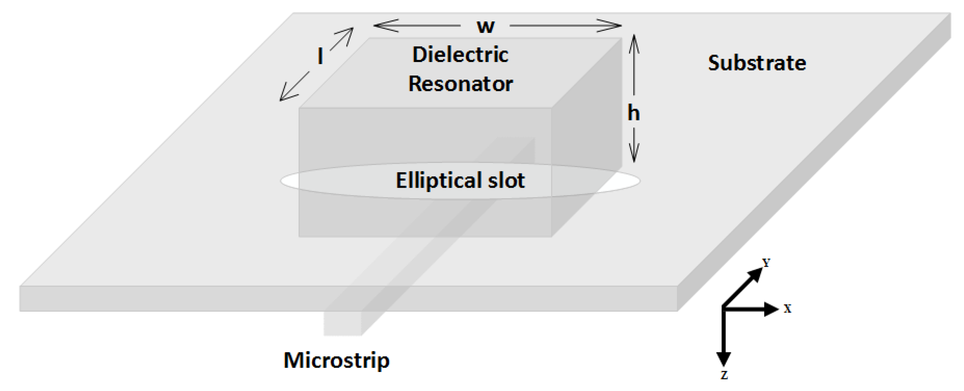
2. Resonating Element

The initiated array is composed of four resonating elements, each comprising a RDR coupled to an ES. In this section, the fundamentals of the resonating elements are described.

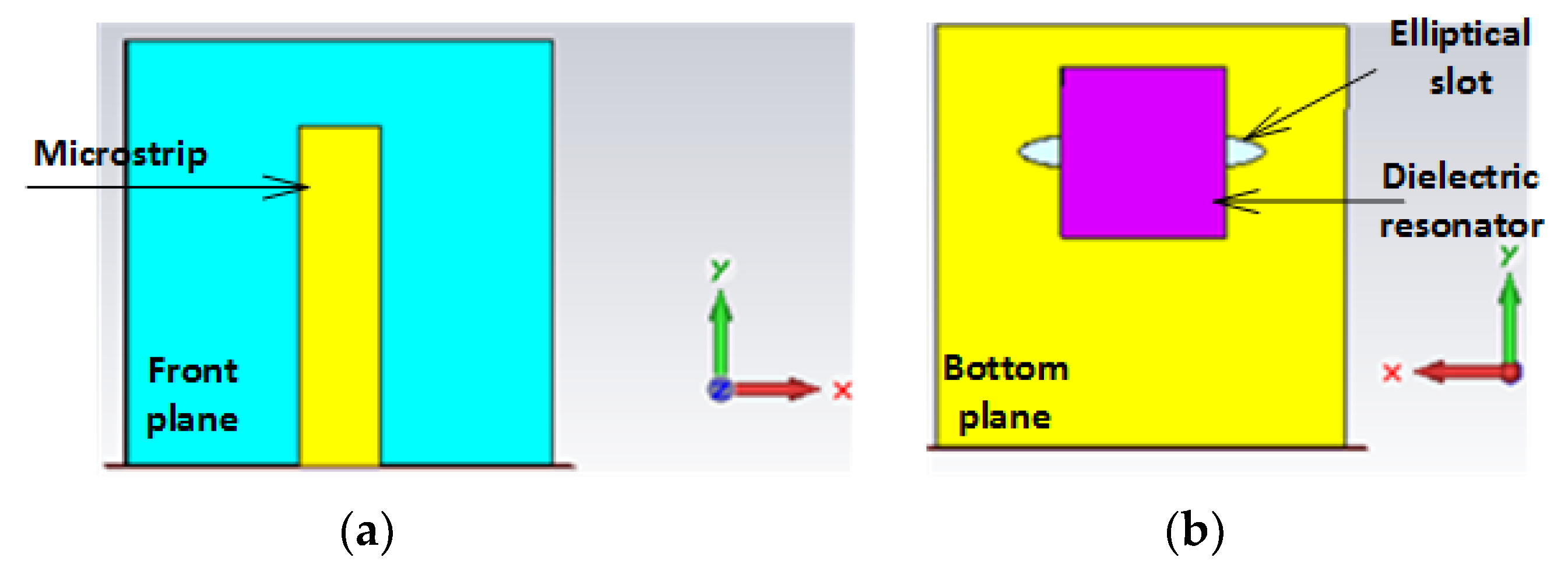
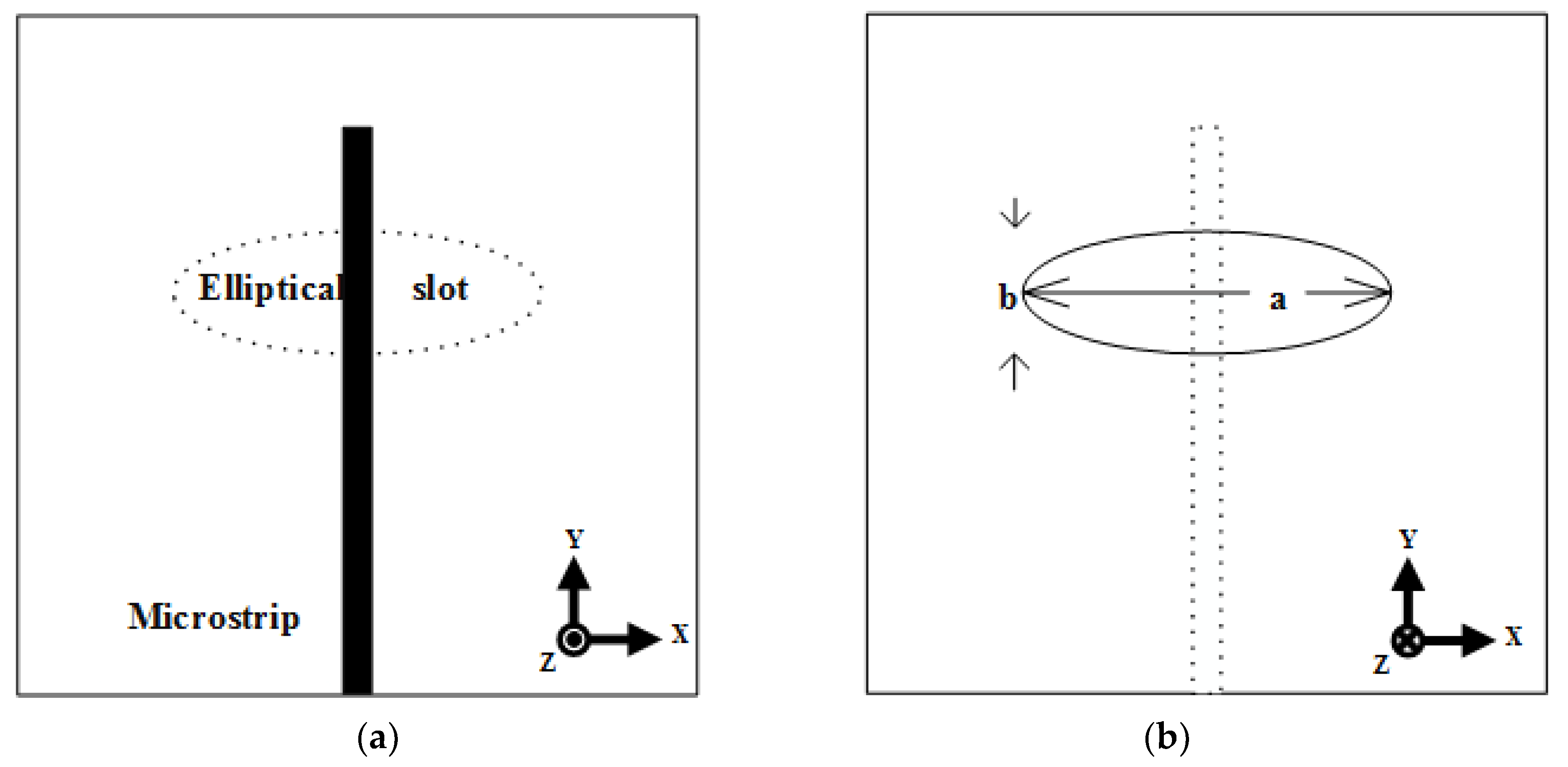
2.1. Elliptical Slot

Traditional rectangular and circular slot functions at a single-resonant frequency exhibit linear polarization. In contrast, the ES can excite the f 11 e , o , the two-fold frequency corresponding to T M 11 o   and T M 11 e modes, required for circular polarization radiation while retaining a single simple feed. The ESs have a characteristically thin bandwidth, low gain, and low efficiency. The ESs can resonate and emit radiation excellently only in the vicinity of the resonant frequency.
Figure 1 depicts an ES carved on the bottom side and coupled to a microstrip on the top side. The semi-major a and semi-minor b axes of the ES are chosen to maintain a low b/a ratio, thereby increasing the eccentricity. Owing to the axis similarity, the ES generates two resonating frequencies corresponding to the dominant even and odd modes. The eccentricity as a design factor offers supplementary elasticity and improves the practicality of elliptical structures. A higher eccentricity leads to a larger bandwidth [13]. Consequently, accurate resonant frequency calculations are critical and essential. The theoretical phenomena for calculating the resonance frequency of an ES were reported in [14,15]. The eccentricity relation can be described by Equation (1).
e = 1 b a 2
The ES generates two resonant frequencies corresponding to the dominant even and odd modes. These two resonant modes can be determined using Equation (2), as reported in [16]:
f 11 e , o = 15 π e a q 11 e , o ε r   GHz
where f 11 e , o is the two-fold frequency corresponding to T M 11 e and T M 11 o   modes, respectively, while ε r is the permittivity of the used substrate.
The approximated Mathieu function q 11 e , o for even and odd mode is given by Equations (3) and (4):
q 11 e = 0.0049 e + 3.7888 e 2 0.7228 e 3 + 2.2314 e 4
q 11 o = 0.0063 e + 3.8316 e 2 1.1351 e 3 + 5.2229 e 4
The resonant frequencies come close to each other as the eccentricity decreases and vice versa.

2.2. Rectangular Dielectric Resonator

The RDR shape has the advantage over other shapes because its dimensions can be chosen independently, which enables dimensional freedom selection [17]. The rectangular geometry offers further elasticity with respect to aspect ratios and bandwidth management [18]. A dielectric waveguide model was employed to investigate the rectangular DRA [19]. Once the DRA is placed on the bottom plane, the TE modes are triggered. Equation (5) is used to calculate the resonant frequency of the fundamental mode TE111 [20]. The proposed single resonating element is depicted in Figure 2.
f 0 = c 2 π ε r k x 2 + k y 2 + k z 2
where εr is the dielectric constant, c the speed of light, and k0 the wave number in free space, while kx, ky, and kz represent the wave number in x, y and z-directions inside the DR, respectively.
The dielectric wave guide mode (DWM) provides no mathematical formula for calculating the resonant frequency for higher-order modes. These modes can be determined by monitoring the electric field distribution within the DR. Higher resonant frequencies correspond to higher TE modes. For the proposed design of an ES coupling a RDR, the simulated E-field distribution plot is illustrated in Figure 3. It can be observed from the figure that totally two orthogonal modes are obtained, namely T E δ 21 x   and T E 1 δ 1 y at 5.8 GHz.

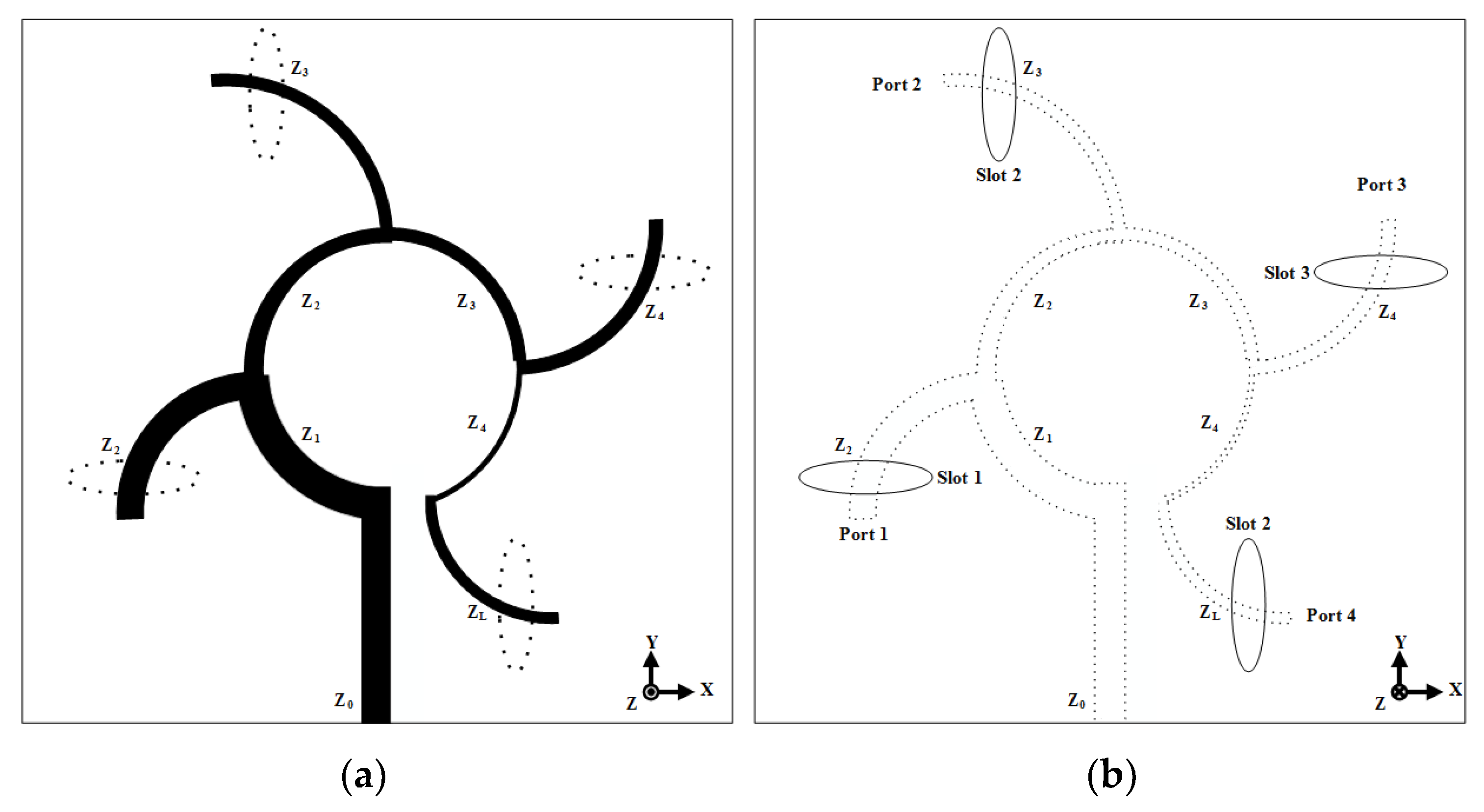
3. Array Feeding Topology

Figure 4 depicts the proposed feed network, which is composed of four curved quarter-wave transformer sections connected together in a successive order to formulate a four-port network. The array is formed as a sequential rotated architecture of series and parallel assembly to layout four output port networks. The quarter-wave segments were prototyped in a circular outline to decrease discontinuity. The feeding topology generates a phase shift of 90° and an equal power split for neighboring output ports. The signal magnitudes of four output ports that are fed to each resonating element are theoretically equal; however, there exists a phase difference of 90° between the two adjacent ports.
The width of all the microstrip segments is a quarter-wavelength with different inherent impedances depending on the binomial quarter-wavelength transformer theory. The binomial theory was used to form the four output ports as an input impedance of 50 Ω to match with 100 Ω at the last segment. Once the characteristic impedances are found, the widths of the microstrip sections can be determined. Table 1 lists the corresponding impedance and width of each segment.
The multi-segment quarter-wavelength transformer is employed to decrease the current attenuation along the array fed, and consequently, increase the coupled power to array radiating elements. Figure 5 reveals that reducing the input impedance leads to an increase in current transmission, resulting in a rise in the obtained power. It can be seen that sufficient current flows throughout the feeding network to reach all the radiating elements.
Figure 6 shows the power allocation over the feeding network. It can be seen from the figure that the power takes place exactly above the coupling slots on the bottom plane, resulting in the maximum power being transferred to the DRs. This proves that the power nodes take place at the desired locations based on the calculated dimensions of the feeding array network.

4. Measurement Results and Discussions

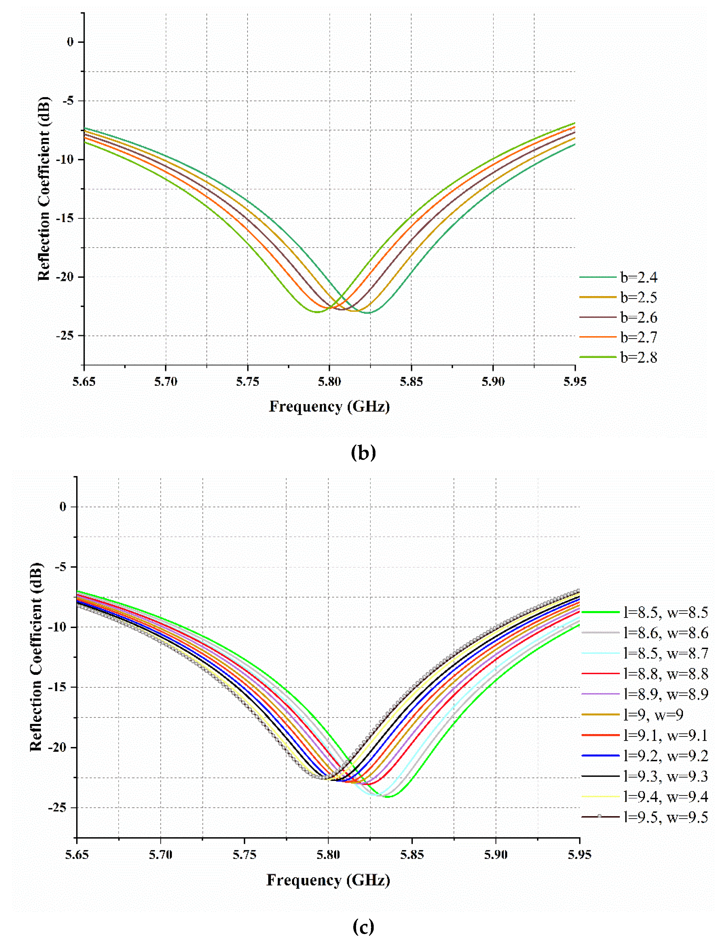
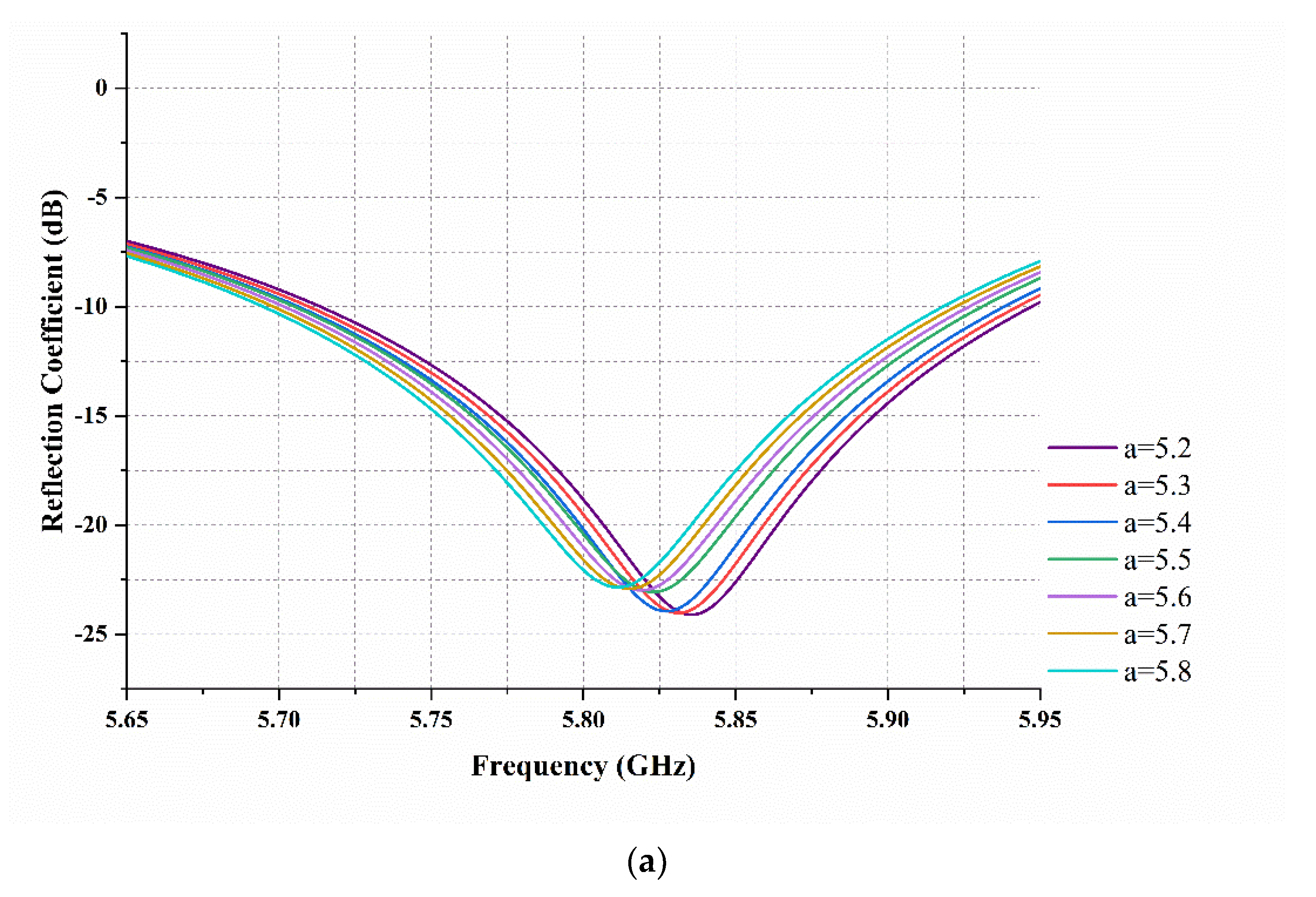
4.1. Single Element Parametric Study

The single RDR coupled to an ES shown in Figure 7 is firstly prototyped and numerically simulated to clarify the relationship between the proposed antenna parameters to achieve optimum performance. Figure 8 depicts the parametric study carried out to optimize the ES radii when coupled to the RDR. Figure 8a shows that if the radius a varies from 5.8 to 5.2 mm, the resonance is shifted to the left as the radius a increases. Figure 8b shows the resonance variation according to changes in the radius b. It is also observed that the resonance moves toward the left as b increases. To fine tune the resonance at 5.8 GHz, the radii dimensions for a and b were selected to be 5.5 and 2.5 mm, respectively. Figure 8c shows the resonance behavior once the length and width of the RDR is varied between 8.5 to 9.5 mm if the height is kept constant at 6 mm. The optimum resonance occurs if the length and width are 9 mm with −22.9 dB at 5.81 GHz.
Figure 9 depicts the AR variation at the main beam angle of 0° with respect to the ES radii a and b alteration while keeping the dimensions of the RDR unchanged. From Figure 8a, it can be observed that if the radius a increases, the 3 dB AR bandwidth moves toward higher frequency. Also, Figure 8b shows that the 3 dB AR bandwidth shifts toward the left as the radius b decreases. The optimum polarization purity occurs when radii a and b equal 5.5 and 2.5 mm respectively.

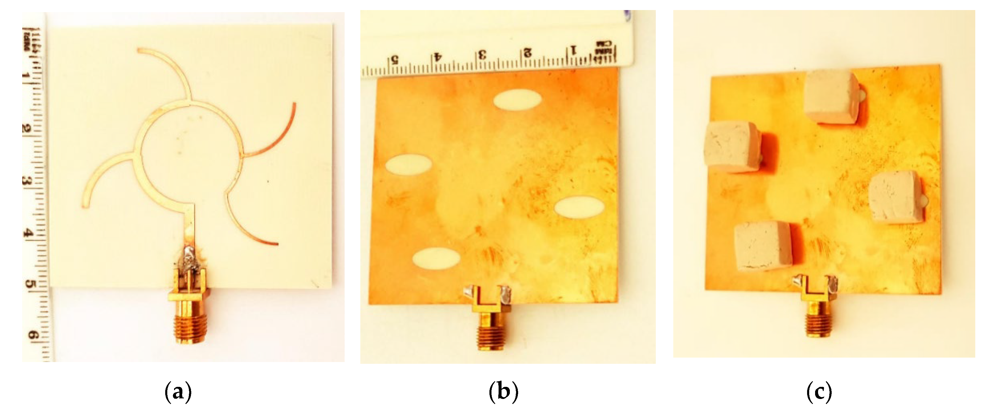
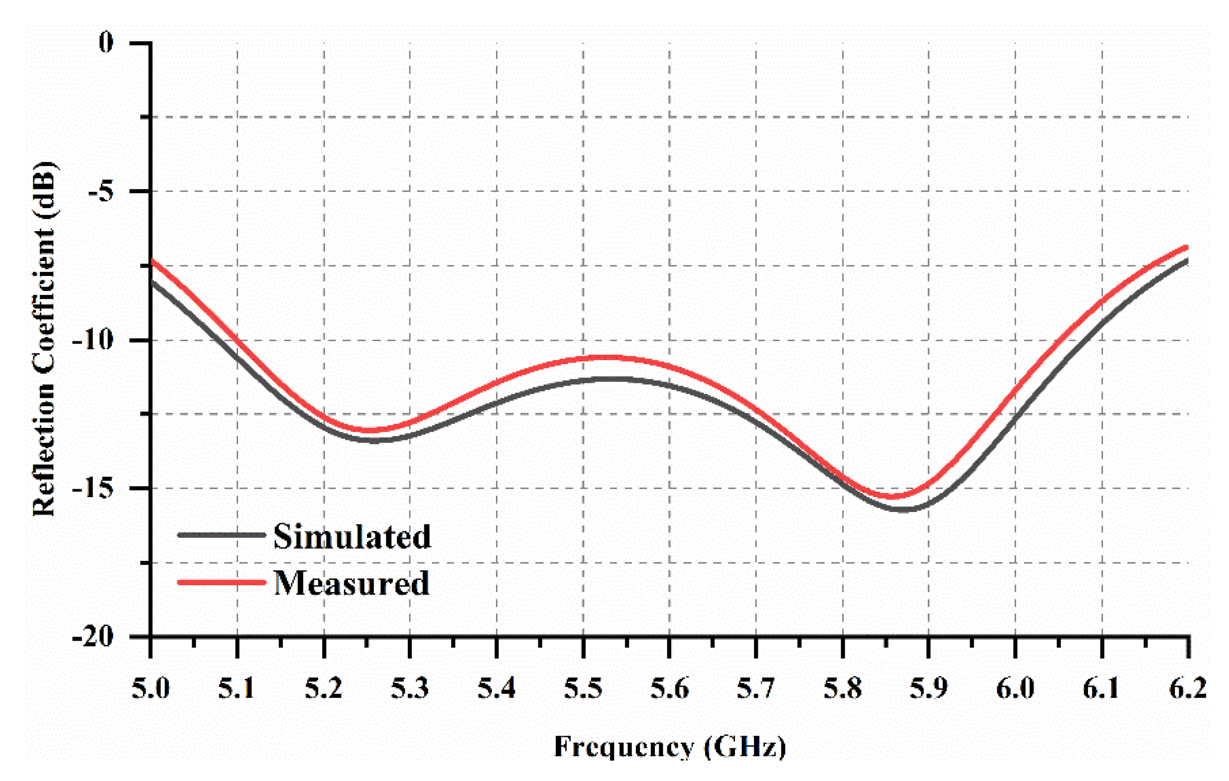
4.2. SR 2 × 2 Array Results

Figure 10 shows the assembled geometry of the proposed CP DRA array. The proposed antenna uses Duroid RO4003C as a substrate with a dielectric constant of 3.38 from Rodgers. The substrate size was 54 × 50 × 0.813 mm3. The DRs were made of E-11 material from T-cream with a dielectric constant of 11.5. The dimensions of the resonating elements were fine-tuned to achieve optimum performance. The DR dimensions were 9, 9, and 6 mm in length, width, and height, respectively. The elliptical slots were printed at the bottom of the substrate with radius a equal to 5.5 mm and radius b equal to 2.5mm. On the other side of the substrate, copper was etched to form a microstrip feed network.
Figure 11 shows the simulated and measured return losses. The minimal measured resonance was achieved at 5.87 of −15.72 dB, whereas the bandwidth ranged from 5.1 to 6.05 GHz. Meanwhile, the simulated resonance achieved a value of −15.28 dB at 5.85 GHz and a bandwidth that ranged from 5.078 to 6.08 GHz. The agreement between the simulated and measured return losses was acceptable, which was attributed to the accuracy of the simulation enlivenment settings and measurement conditions.
Figure 12 illustrates the simulated and measured electric fields at the electric co-polarized and electric cross-polarized planes at a frequency of 5.8 GHz. From the figure, we can infer that the polarization is a left-hand circular polarization (LHCP) in the broad side direction. The difference between the cross-polarization and co-polarization at the xz-plane was approximately −20 dB.
Figure 13 shows the simulated and measured gains over the resonance ranges. The maximum simulated gain occurs at 5.35 GHz of 10.32 dBi, while that of the measured gain occurs at 5.34 GHz of 10.24 dBi. The measured gain was extracted using a gain transfer method using a helical antenna as a reference. A reflector at the feeding network side might be used to increase the gain performance. The simulated total efficiency ranges from 0.7% to 0.9, confirming the effectiveness of the design.
Figure 14 shows the simulated and measured ARs at the main angle of 0°. The simulated AR bandwidth ranges from 5.08 to 6.08 GHz, while the measured AR ranges from 5.05 to 6.05 GHz. The simulated and measured AR impedance bandwidth was 17.9% and 18% respectively. The agreement between the simulated and measured results was fairly good.

5. Conclusions

In this study, a novel 2 × 2 SR CP DRA array antenna with a compact size of 54 × 50 mm2 was introduced. The antenna array was composed of four different radiating elements, each composed of a RDR mounted over an elliptical slot. The elliptical slot was used to excite two orthogonal modes within the DR that were required for the CP operation. The array exhibited an impedance bandwidth of 17% operating in the IEEE 802.11a band. The sequentially rotated series–parallel stub technique was employed to construct the feed network to allow symmetrical positioning of microstrip patch elements, which resulted in a good AR bandwidth of 18%. The antenna gain within the operating frequency was a maximum of 10.24 dBi. A comparison between the proposed antenna with the other 2 × 2 SR CP DRA array reported in the literature is presented in Table 2. The design can be further enhanced by applying the concept of frequency reconfigurability. The approach presented by [21] of using water to vary the antenna resonance seems to be interesting for future work.

Author Contributions

Y.Q., data interpretation, and methodology; A.A., writing, review and editing; A.S.A., project administration. All authors have read and agreed to the published version of the manuscript.

Funding

The authors would like to thank the Deanship of Scientific Research at Majmaah University for supporting this work under project number R-2021-223.

Institutional Review Board Statement

Not applicable.

Informed Consent Statement

Not applicable.

Data Availability Statement

The data are contained within the article.

Conflicts of Interest

The authors declare no conflict of interest.

References

  1. Long, S.A.; McAllister, M.W.; Shen, L.C. The resonant cylindrical dielectric cavity antenna. IEEE Trans. Antennas Propag. 1983, 31, 406–412. [Google Scholar] [CrossRef]
  2. Junker, G.P.; Kishk, A.A.; Glisson, A.W. Input impedance of dielectric resonator antennas excited by a coaxial probe. IEEE Trans. Antennas Propag. 1994, 42, 960–966. [Google Scholar] [CrossRef]
  3. Martin, J.T.; Antar, Y.M.; Kishk, A.A.; Ittipiboon, A.; Cuhaci, M. Dielectric resonator antenna using aperture coupling. Electron. Lett. 1990, 26, 2015–2016. [Google Scholar] [CrossRef]
  4. Simons, R.N.; Lee, R.Q. Effect of parasitic dielectric resonator onCPW/aperture-coupled dielectric resonator antenna. Proc. Inst. Elect. Eng. Microw. Antennas Propag. 1993, 140, 336–338. [Google Scholar] [CrossRef]
  5. Lam, H.Y.; Leung, K.W. Analysis of U-slot-excited dielectric resonator antennas with a backing cavity. Proc. Inst. IEE Proc. Microw. Antennas Propag. 2006, 153, 480–482. [Google Scholar] [CrossRef]
  6. Lim, B. Dielectric Resonator Antennas: Theory and Design. Master’s Thesis, Massachusetts Institute of Technology, Cambridge, MA, USA, 1999. [Google Scholar]
  7. Petosa, A.; Ittipiboon, A.; Cuhaci, M. Array of circular-polarized cross dielectric resonator antennas. Electron. Lett. 1999, 32, 1742–1743. [Google Scholar] [CrossRef]
  8. Pang, K.K.; Lo, H.Y.; Leung, K.W.; Luk, K.M.; Yung, E.K. Circularly polarized dielectric resonator antenna subarrays. Microw. Opt. Technol. Lett. 2000, 27, 377–379. [Google Scholar] [CrossRef]
  9. Laisné, A.; Gillard, R.; Piton, G. Circularly polarised dielectric resonator antenna with metallic strip. Electron. Lett. 2002, 38, 106–107. [Google Scholar] [CrossRef]
  10. Kishk, A.A. Application of rotated sequential feeding for circular polarization bandwidth enhancement of planar arrays with single-fed DRA elements. In Proceedings of the IEEE Antennas and Propagation Society International Symposium, Columbus, OH, USA, 22–27 June 2003; pp. 664–667. [Google Scholar]
  11. Yang, S.S.; Chair, R.; Kishk, A.A.; Lee, K.F.; Luk, K.M. Study on sequential feeding networks for subarrays of circularly polarized elliptical dielectric resonator antenna. IEEE Trans. Antennas Propag. 2007, 55, 321–333. [Google Scholar] [CrossRef]
  12. Lin, J.H.; Shen, W.H.; Shi, Z.D. Circularly polarized dielectric resonator antenna arrays with fractal cross-slot-coupled DRA elements. Int. J. Antennas Propag. 2017, 2017, 1–11. [Google Scholar] [CrossRef]
  13. Raheja, D.K.; Kanaujia, B.K. Design and analysis of elliptical slot loaded microstrip antenna for C-Band communication. In Proceedings of the 3rd International Conference on Computing for Sustainable Global Development (INDIACom), New Delhi, India, 16–18 March 2016. [Google Scholar]
  14. Liang, S.L. The elliptical microstrip antenna with circular polarization. IEEE Trans. Antennas Propag. 1981, 29, 90–94. [Google Scholar] [CrossRef]
  15. Bailey, M.; Deshpande, M. Analysis of elliptical and circular microstrip antennas using moment method. IEEE Trans. Antennas Propag. 1985, 33, 954–959. [Google Scholar] [CrossRef]
  16. Kretzschmar, J.G. Wave propagation in hollow conducting elliptical waveguides. IEEE Trans. Microw. Theor. Tech. 1970, 18, 547–554. [Google Scholar] [CrossRef]
  17. Mongia, R.K.; Ittipiboon, A. Theoretical and experimental investigations on rectangular dielectric resonator antennas. IEEE Trans. Antennas Propag. 1997, 45, 1348–1356. [Google Scholar] [CrossRef]
  18. Lukui, J.; Lee, R.; Robertson, I. A dielectric resonator antenna array using dielectric insular image guide. IEEE Trans. Antennas Propag. 2014, 63, 859–862. [Google Scholar]
  19. Legier, J.F.; Kennis, P.; Toutain, S.; Citerne, J. Resonant frequencies of rectangular electric resonators. IEEE Trans. Microw. Theor. Tech. 1980, 28, 1031–1034. [Google Scholar] [CrossRef]
  20. Ittibipoon, A.; Mongia, R.K.; Cuhaci, M. Low profiled electric resonator antennas using a very high permittivity material. Electron. Lett. 1994, 30, 1362–1363. [Google Scholar]
  21. Jacobsen, R.E.; Lavrinenko, A.V.; Arslanagić, S. A Water-Based Huygens Dielectric Resonator Antenna. IEEE Open J. Antennas Propag. 2020, 1, 493–499. [Google Scholar] [CrossRef]
Figure 1. Schematic of open-ended microstrip line with ES: (a) Front plane; (b) Ground plane.
Applsci 11 08779 g001
Figure 2. The 3D geometry of the proposed RDR coupled to an ES at the bottom plane.
Applsci 11 08779 g002
Figure 3. E-field distributions within the rectangular DRA coupled to an ES.
Applsci 11 08779 g003
Figure 4. Configuration of the proposed array feed: (a) Front plane; (b) Bottom plane.
Applsci 11 08779 g004
Figure 5. Current flow through the feeding array network.
Applsci 11 08779 g005
Figure 6. Power distribution in the feeding array network.
Applsci 11 08779 g006
Figure 7. The modeled single resonating element: (a) Front plane; (b) Bottom plane.
Applsci 11 08779 g007
Figure 8. Reflection coefficient variation with respect to ES radii: (a) Radius a; (b) Radius b; (c) RDR dimensions variations.
Applsci 11 08779 g008aApplsci 11 08779 g008b
Figure 9. The AR variation corresponding to elliptical slot radii alteration: (a) Radius a; (b) Radius b.
Applsci 11 08779 g009
Figure 10. Photograph of the fabricated single element DRA: (a) The feeding network printed on the front plan; (b) The elliptical slots etched on the ground plan; (c) The dielectric resonators placed on the elliptical slots.
Applsci 11 08779 g010
Figure 11. Simulated and measured return losses.
Applsci 11 08779 g011
Figure 12. Simulated and measured electric co-polarized and electric cross-polarized fields.
Applsci 11 08779 g012
Figure 13. Simulated and measured gains and simulated total efficiency.
Applsci 11 08779 g013
Figure 14. Simulated and measured axial ratios.
Applsci 11 08779 g014
Table 1. Width and characteristic impedance of the transformers.
Transformer ElementWidth [mm]Characteristic Impedance [Ω]
Z01.89850
Z11.7752.21
Z21.3262.09
Z30.79680.52
Z40.53995.75
Z Load0.483100
Table 2. Comparison between the proposed array and other 2 × 2 SR CPs.
ReferenceSize [mm]Bandwidth %Axial Ratio %Peak Gain (dBi)
[7]Not mentioned25168
[8]Not mentioned141612
[11]80 × 80442610
Proposed work54 × 50171810.24
Publisher’s Note: MDPI stays neutral with regard to jurisdictional claims in published maps and institutional affiliations.

