Article

Evaluating the Seismic Capacity of Dry-Joint Masonry Arch Structures via the Combined Finite-Discrete Element Method

1
School of Civil Engineering, Suzhou University of Science and Technology, Suzhou 215011, China
2
Department of Civil Engineering, The City College of New York, New York, NY 10031, USA
3
School of Engineering, University of Tasmania, Hobart 7001, Australia
*
Author to whom correspondence should be addressed.
Appl. Sci. 2021, 11(18), 8725; https://doi.org/10.3390/app11188725
Submission received: 16 August 2021 / Revised: 16 September 2021 / Accepted: 17 September 2021 / Published: 18 September 2021
(This article belongs to the Topic Advances on Structural Engineering)

Abstract

:
The behaviour of dry-joint masonry arch structures is highly nonlinear and discontinuous since they are composed of individual discrete blocks. These structures are vulnerable to seismic excitations. It is difficult for traditional methods like the standard finite element method (FEM) to simulate masonry failure due to their intrinsic limitations. An advanced computational approach, i.e., the combined finite-discrete element method (FDEM), was employed in this study to examine the first-order seismic capacity of masonry arches and buttressed arches with different shapes subjected to gravity and constant horizontal acceleration. Within the framework of the FDEM, masonry blocks are discretised into discrete elements. A finite element formulation is implemented into each discrete element, providing accurate predictions of the deformation of each block and contact interactions between blocks. Numerical examples are presented and validated with results from the existing literature, demonstrating that the FDEM is capable of capturing the seismic capacities and hinge locations of masonry arch structures. Further simulations on geometric parameters and friction coefficient of masonry buttressed arches were conducted, and their influences on the seismic capacities are revealed.

1. Introduction

Masonry arches have been the traditional forms of architectural heritages and historical constructions for a long time. They are assemblages of voussoirs made of stones or bricks, which are either bonded with low-strength mortar or completely mortarless. In this regard, a dry-joint assumption can be reasonably held. Moreover, masonry arch structures are vulnerable to seismic excitations. Due to the intrinsic discontinuities, their responses under seismic excitations are highly nonlinear. Thus, research into the seismic capacity of dry-joint masonry arch structures is required.
If fracture and sliding are not considered, the dynamic failure of masonry arches can be determined by the hinge failure mechanism following Heyman’s hypothesis [1] that masonry voussoirs have zero tensile strength and infinite compressive strength, as well as large enough friction between them. Some pioneering work has been proposed based on analytical limit analysis. Oppenheim [2] investigated the dynamic response of an unreinforced masonry arch by a four-link mechanism, in which the arch was modelled as three rigid bars with predefined hinges. Subsequently, the same approach was employed to study the performance of circular stone arches subjected to base excitations [3,4]. Baratta et al. [5] examined the seismic responses of a simple masonry arch portal subjected to horizontal seismic forces, and, moreover, the vertical overload due to volcanic ash fall following an eruption event was considered. De Lorenzis et al. [6] proposed a simplified analytical formulation and evaluated the behaviour of arches under impulse base motions.
Shaking table testing is the most direct approach to evaluate the seismic behaviour of masonry arch structures, and considerable work has been conducted (Silva et al. [7], Gaetani et al. [8], etc.). However, almost all of them utilised small-scale models since full-scale testing [9] was too expensive, or the tested models were too large (or heavy) and far beyond the capacity of testing facilities. Therefore, numerical simulation has become more popular. The finite element method (FEM) and the discrete element method (DEM) are two commonly used approaches. De Luca et al. [10] proposed an algorithm by coupling linear FEM and limit analysis, and, based on it, they investigated the seismic capacity of three triumphal arches of Neapolitan churches. De Santis and de Felice [11] presented a fibre beam-based FEM approach, and with it, they studied the seismic capacity of masonry arches of different shapes and materials. In addition, the FEM software ABAQUS has also been employed to reproduce the global bond behaviour in SRG-strengthened masonry prisms [12].
Since masonry arches are highly discontinuous, it is very difficult for the FEM to capture their potential failure processes under seismic excitations due to the intrinsic limitations. The DEM, which is naturally suitable for modelling discontinuous structures and heterogeneous materials, has great advantages in predicting the seismic capacity of masonry arches. Giordano et al. [13] reviewed the applicability of different numerical techniques, including the DEM code UDEC, in analysing masonry structures and compared the results with test data. Bićanić et al. [14] presented the discontinuous analysis of a masonry arch bridge under vertical loading up to failure, with the inclusion of DEM modelling. More work on the DEM in simulating the seismic failure of masonry arch structures can be found in [6,15,16,17]. Some other DEM-based applications on masonry structures are also available in a variety of literature. For small-scale modelling, Foti et al. [18] predicted the failure of dry-joint masonry cross vaults subjected to support settlements. For large-scale simulations, endeavours have been made on masonry arches [19], arch bridges [20], aqueducts [21,22] etc.
Besides the limit analysis, the FEM and the DEM mentioned above, other methods like the two-step procedure [23] have also been employed in analyses of the seismic capacity of masonry structures in general.
Though traditional DEM uses rigid blocks, new computational approaches also include deformation in the blocks, e.g., UDEC, 3DEC, ABAQUS etc. The combined finite-discrete element method (FDEM) developed by Munjiza [24,25,26,27] is an extension of the FEM and the DEM. With it, structures are discretised into numbers of discrete elements. Within each discrete element, a finite element mesh is incorporated. Consequently, more accurate predictions on the contact forces between elements and the deformation of structures can be achieved. Further details on the FDEM can be referred to the monographs of Munjiza and his co-workers [28,29,30]. The FDEM has been employed to simulate the failure of brittle or quasi-brittle materials, such as glass impact fracture [31,32], shell fracture [33], slope instability [34], rock compression fracture [35] etc. Applications of the FDEM on structural engineering were comprehensively summarised by Munjiza et al. [36]. Regarding the FDEM applications on masonry, Smoljanović et al. [37,38,39,40] analysed the static and dynamic behaviour of both dry-stone and mortared masonry structures subjected to different loads. Balic et al. [41] examined the collapse mechanism of stone arches due to seismic excitations. Recently, the FDEM has been employed to study the collapse of masonry arch structures subjected to base impulses [42] and support spreading [43], as well as the failure of masonry walls under uneven support settlements [44].
The seismic capacity of masonry arches is worthy of investigating with the FDEM, and a good attempt has been made in this paper to enrich the FDEM applications in structural engineering. Herein, the terminology ‘seismic capacity’ corresponds to the first-order seismic capacity of masonry arch structures under the combination of gravity and constant horizontal acceleration. Under such loading, the failure of masonry arch structures is a dynamic process. Therefore, the FDEM is an appropriate simulation tool, and the 2D FDEM program ‘Y’ [45] is employed in this study. The layout for the rest of the paper is as follows. Fundamentals on the FDEM modelling are addressed in Section 2. Numerical examples, including a variety of arch structures subjected to both gravitational and constant horizontal accelerations, are presented in Section 3. A parametric investigation regarding geometric parameters and friction coefficient are conducted in Section 4. Finally, the conclusions are reached in Section 5.

2. FDEM Modelling

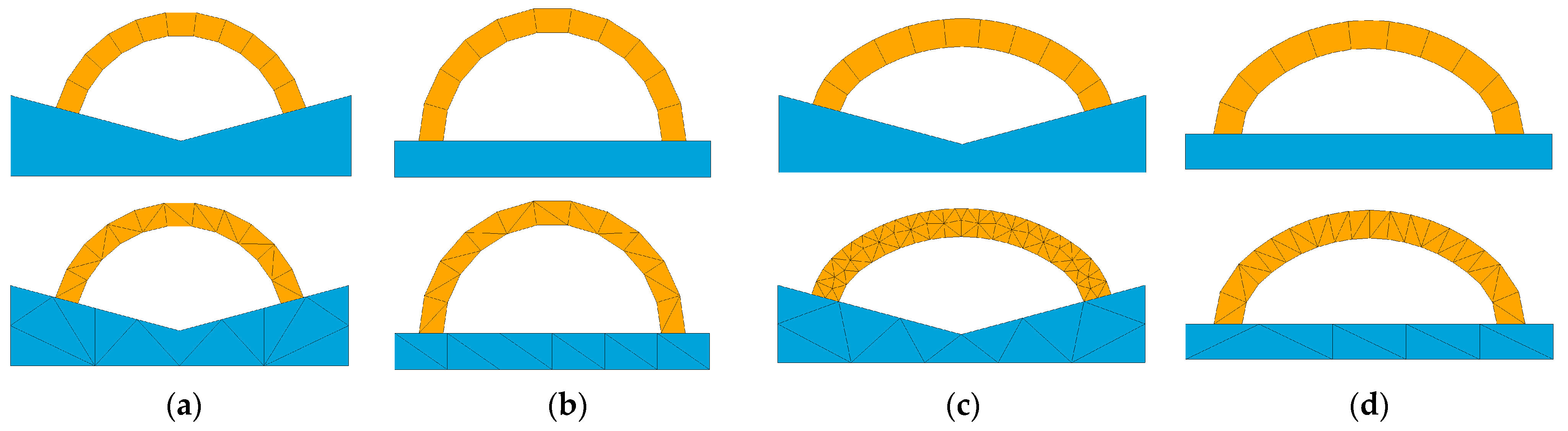
2.1. Voussoir Discretisation

Dry-joint masonry arches are composed of voussoirs. Within the framework of the FDEM, each voussoir is an individual discrete block and is meshed with numbers of three-node constant strain triangular (CST) elements. The discretisation of two adjacent voussoirs, A and B, are illustrated in Figure 1. In this study, the fracture behaviour of voussoir is not included. Hence, no element interface (i.e., joint element) needs to be defined between adjacent elements within a single block, implying voussoirs A and B cannot be further divided. Furthermore, the dry-joint assumption suggests that only contact and friction need to be considered between voussoirs A and B.
In this study, a No Binary Search (NBS) contact detection algorithm, called Munjiza-NBS contact detection algorithm [28], was implemented in the FDEM program ‘Y’. One of the advantages of using this algorithm is that the total computational time to detect all the contact couples is proportional to the number of discrete elements, and further details can be found in Munjiza and Andrews [25]. Another important aspect of the FDEM is the contact interaction law defining the contact force, and it will be introduced in Section 2.3.

2.2. Element Motions
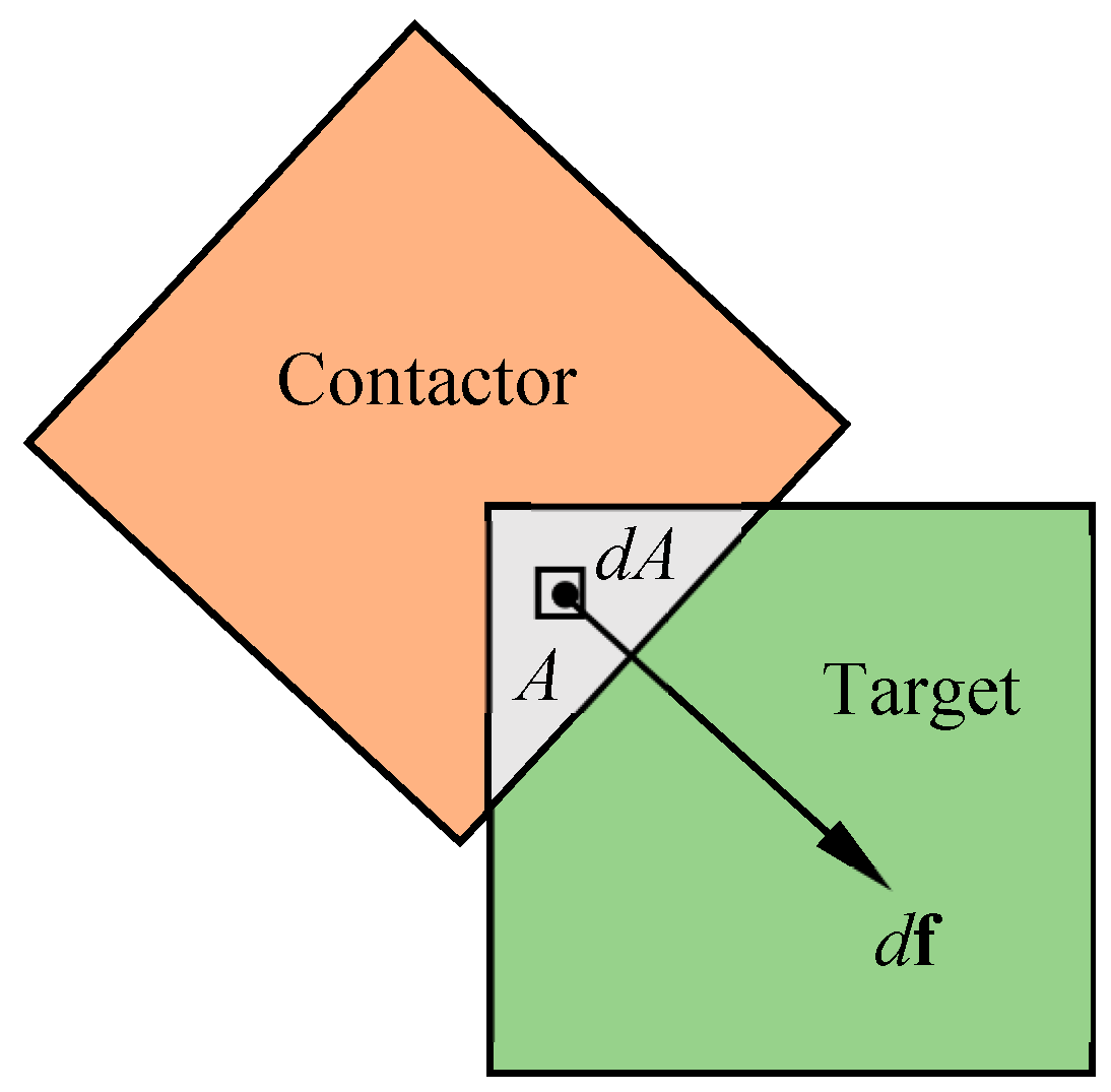
Referring to Munjiza [28], the translational and the rotational motions of an arbitrary discrete element i are formulated according to Newton’s second law of motion, as
m i   ( a + g ) = F i
J i   ω i ˙ = T i
where mi is the mass of discrete element i; a is the acceleration acts on element i with the exclusion of the gravitational acceleration; g is the gravitational acceleration; Ji is the moment of inertia about the centre of element i; ωi is the angular velocity about the element centre; and Fi and Ti are the resultant force and moment act on and about the centre of element i, respectively. According to Equations (1) and (2), the velocity and position of discrete element i can be explicitly obtained at each time step. An explicit central difference time integration scheme is used [28], and the nodal velocity of the next time step is given by Equation (3), as
  v next = v current + a current Δ t
where a is the acceleration of the node, Δt is the time step, v is the velocity, and the subscripts ‘next’ and ‘current’ correspond to the next and the current time step.

2.3. Contact Forces

In the FDEM, the contact force f was evaluated and integrated through the overlapping area A. As shown in Figure 2, the infinitesimal contact force df due to the penetration of elemental area dA is defined in Equation (4), as
d f = d f t + f c
in which dft and dfc are the force components of df from the target and the contactor, respectively, as
d f t = E p grad φ c ( P c ) d A
d f c = E p grad φ t ( P t ) d A
where Pc and Pt are the points on the contactor and the target, respectively, and they share the same coordinate within A; φc and φt are predefined potentials; grad is the gradient; and Ep is the contact penalty and is usually 100 times of the Lame’s first constant. Thus, the contact force f can be obtained by integrating dA over A, as
f = E p A [ grad φ c ( P c ) grad φ t ( P t ) ] d A
Further details on the contact forces can be referred to Munjiza [28].

3. Numerical Examples

In this section, masonry arch structures subjected to the gravitational acceleration g and a constant horizontal acceleration λg were considered. λ is a scale factor, and the maximum λ that masonry arch structures can withstand is denoted as λ*, which indicates their first-order seismic capacity. The 2D analysis was conducted since it is acceptable, accurate enough and time-saving [46].

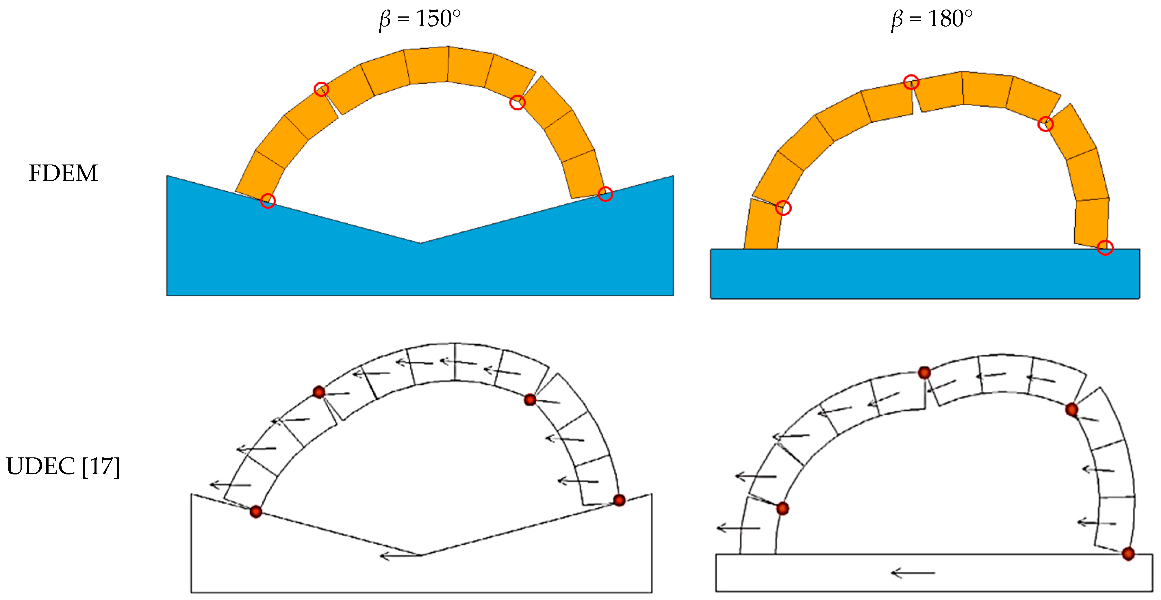
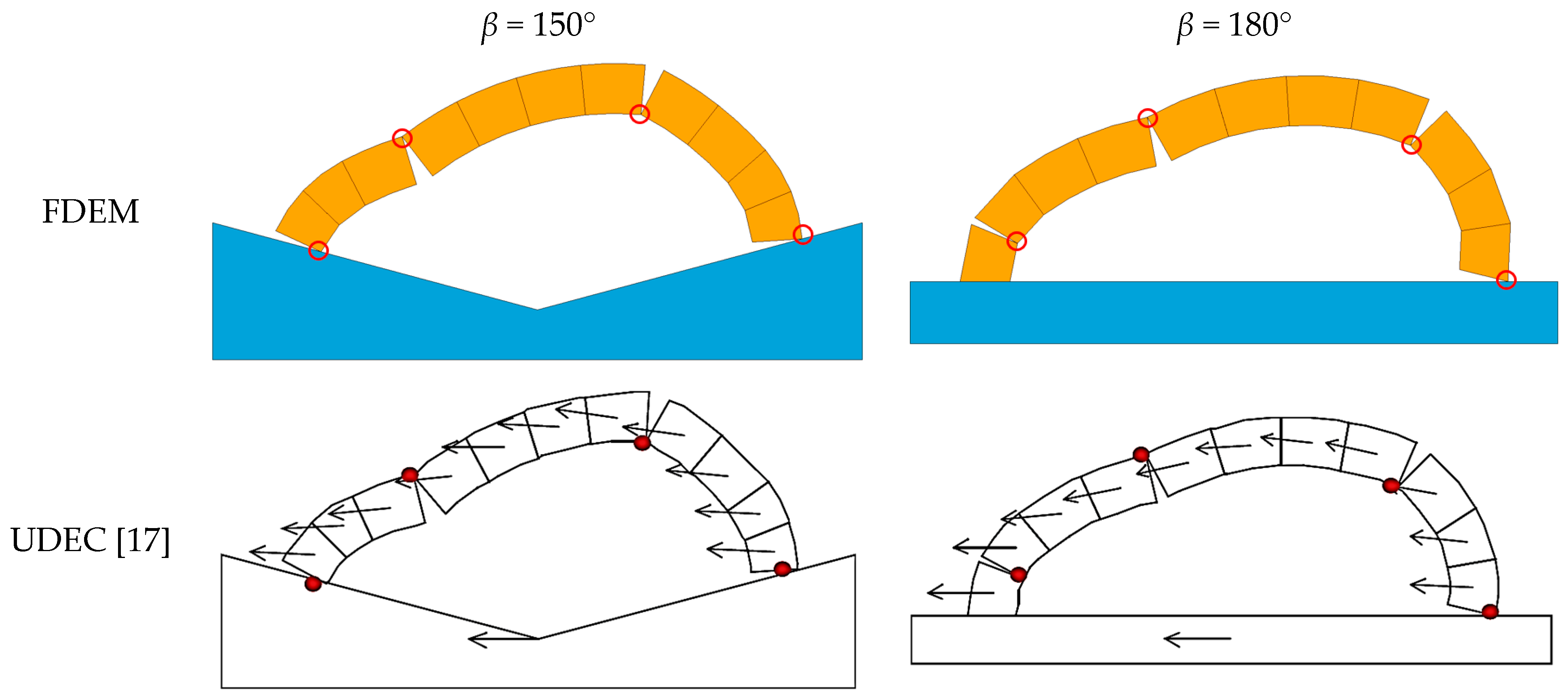
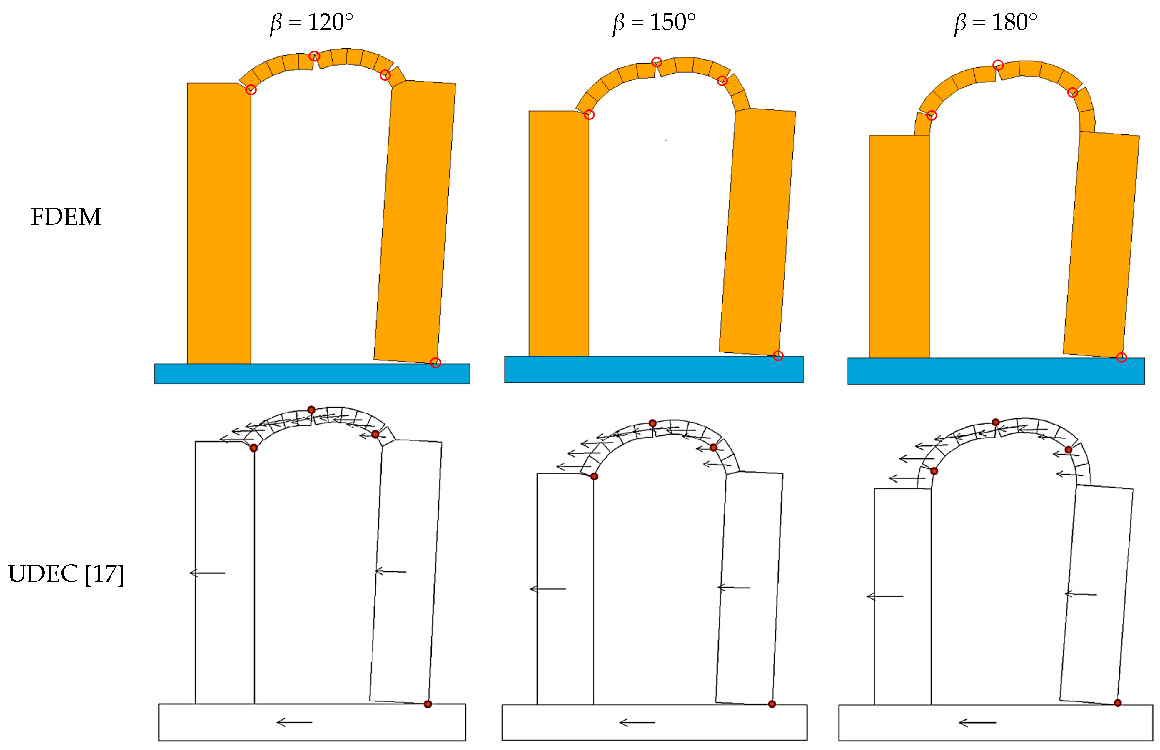
3.1. Arches without Buttresses

Dimitri and Tornabene [17] proposed an analytical model to evaluate the seismic capacity of masonry arches and buttressed arches based on the static theory of limit analysis, and their predictions of the model were also compared and verified with results from the DEM program UDEC [17]. In this section, two types of arches, i.e., the circular arch and the basket-handle arch, were investigated. Their geometric configurations are shown in Figure 3. The circular arch (Figure 3a) is simply characterised by the embrace angle β, the thickness t and the centreline radius Rc. Figure 3b shows the geometry of a basket-handle arch, which is composed of three circular arches: a larger arch with the centre O1, two smaller arches with the centres O2 and O3 and the radius r. d is the distance between O1 and O, where O is the centre of the reference circle (red dash line).
The seismic capacities of two circular arches and two basket-handle arches with the embrace angles β = 150° and β = 180° were investigated. Each arch is composed of 11 voussoirs. The geometric parameters are: (i) circular arches, Rc = 1.0 m and t/Rc = 0.2; (ii) basket-handle arches, Rc = 1.0 m, t/Rc = 0.2, d/Rc = 0.5 and r/Rc = 0.5. The geometric parameters were chosen such that direct comparison could be made with results in the literature [17]. The material properties are shown in Table 1. Mesh configurations of the arches used in the FDEM simulations are illustrated in Figure 4, in which the arches are yellow, the bases are blue and N is the total number of elements. The time step of the simulation was set to 1.0 × 10⁻⁶ s, and a friction coefficient of 0.6 was defined.
The λ* was tested using every single value. For each λ, the simulation was performed for a period of time that was long enough so that the arch would collapse if the assigned λg was larger than its seismic capacity. Should the arch be still standing with little noticeable deformation at the end of the simulation, the structure was considered stable. Otherwise, it was unstable with the corresponding λg. Besides the current approach, a criterion based on the unbalanced force ratio/max velocity could have been a better way and shall be considered in future research. The explicit time integration in the FDEM was automatically terminated once the computed steps reached the predefined maximum step, or it could be terminated manually as long as the arch had collapsed under certain λg. According to Munjiza [28], viscous damping with a value of 2 Δ h E ρ was considered, where Δh is the characteristic size of the smallest element, E is the Young’s modulus and ρ is the material density.
For λ > λ*, all of the four arches failed following the hinge mechanism. Take the instance of the circular arch with β = 180°; the entire failure process with λ = 0.3 was simulated by the FDEM and is presented in Figure 5. Initially, there were five hinges (see Figure 5a). Subsequently, one hinge closed, and the motion of the arch was dominated by the remaining four hinges until collapse, as shown in Figure 5b–d. Finally, the arch lost its stability and collapsed due to significant deformation. The dominant four hinges are denoted as hinge I, II, III and IV in Figure 5d.
The seismic capacity factor λ* of the investigated arches are presented in Table 2, in which e is the relative difference between the simulation results and the results based on limit analysis. Clearly, the results from the FDEM simulation agree very well with the results in Dimitri and Tornabene [17], especially with the analytical results based on limit analysis. However, additional results on the circular and basket-handle arches with β = 120° show that the relative errors are higher, suggesting the limitation of the proposed model. The failure modes of circular and basket-handle arches are shown in Figure 6 and Figure 7, respectively. It is observed that the failure modes predicted from the FDEM simulations are in excellent agreement with the results predicted by the UDEC [17], especially for the hinges and their locations.

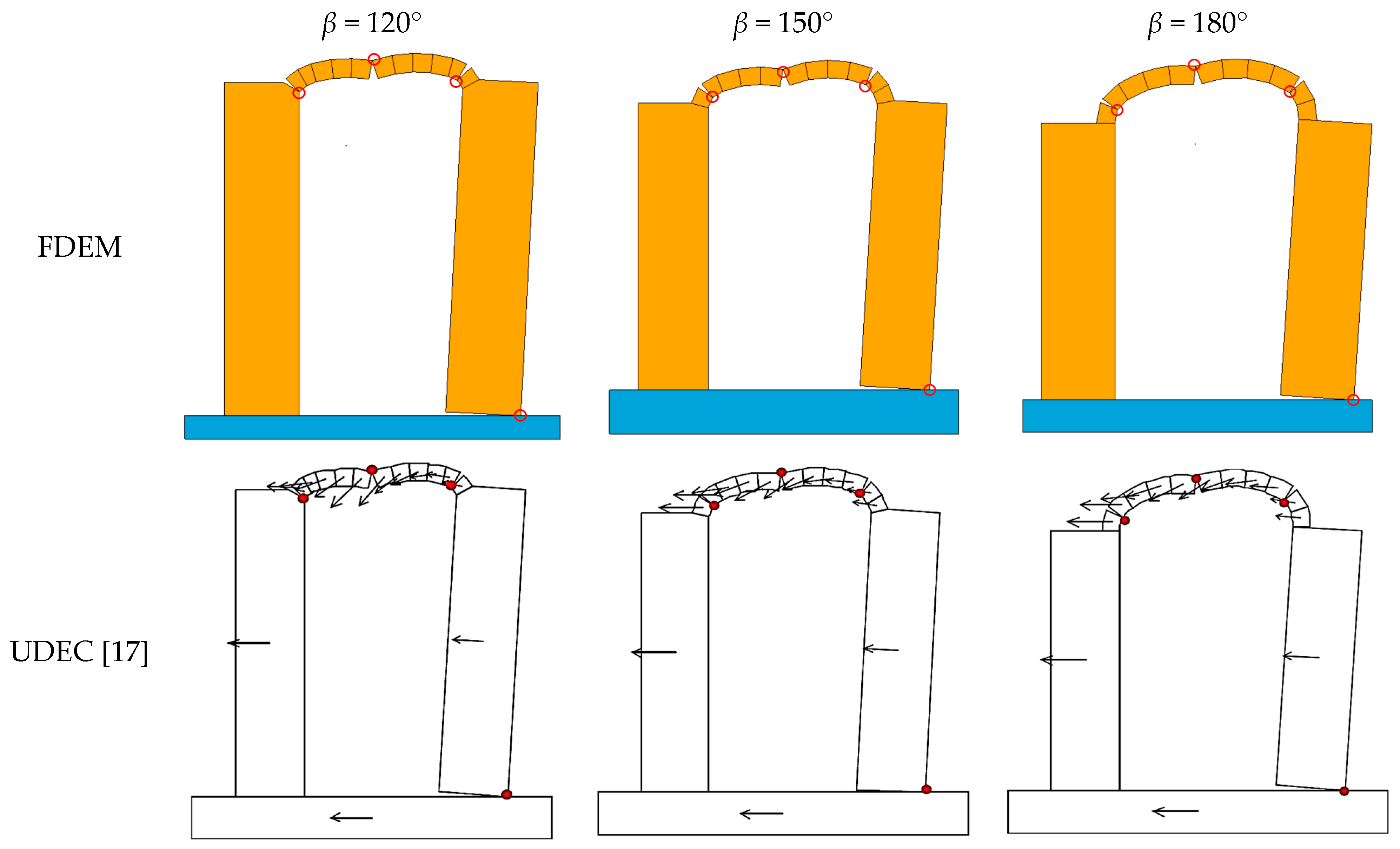
3.2. Buttressed Arches

In this section, two types of buttressed arches are investigated, as shown in Figure 8. The figure is drawn based on Dimitri and Tornabene [17]. The width of the buttress is B, the height from O to the base is H1, the height of the buttress is H, the height from the top of the buttress to the arch crown is h and other parameters are similar to the arches shown in Figure 3.
Similar to that in Section 3.1, each arch is composed of 11 voussoirs. Geometric parameters of the investigated buttressed arches are: (i) circular buttressed arch, Rc = 1.0 m, H1/Rc = 3, B/Rc = 0.8 and t/Rc = 0.2; (ii) basket-handle buttressed arch, Rc = 1.0 m, H1/Rc = 3, B/Rc = 0.8, d/Rc = 0.5, r/Rc = 0.5 and t/Rc = 0.2. The mesh configurations of the buttressed arches are shown in Figure 9, and the total element numbers are: (i) circular buttressed arches, N = 50 for β = 120° and 150°, N = 61 for β = 180°; (ii) basket-handle buttressed arches, N = 50 for β = 120°, N = 58 for β = 150° and N = 63 for β = 180°. The material properties are as same as in Table 1. The time step of the simulation was set to 1.0 × 10⁻⁶ s, and a large friction coefficient of 0.9 was adopted to avoid potential sliding. Similarly, failure of all buttressed arches followed the four-hinge mechanism, too. Herein, the buttressed basket-handle arch with β = 180° was chosen and presented representatively, and the failure process with λ = 0.18 is shown in Figure 10. At the first instance (Figure 10a), four hinges initiated quickly. Three upper hinges (one extrados hinge and two intrados hinges) appeared within the arch, and a lower hinge formed at the bottom of the right buttress; therefore, the entire structure behaved as a linked mechanism. The hinges continued to develop till the collapse of the structure.
The seismic capacity factors λ* of the buttressed basket-handle arches are presented in Table 3, including the results from Dimitri and Tornabene [17]. Apparently, the FDEM simulation results agree well with the results based on the limit analysis and the UDEC simulation. The failure modes of buttressed basket-handle arches are illustrated in Figure 11 and Figure 12. All the structures failed due to the instability of the four-hinge mechanism, and the simulation results by the FDEM are in excellent agreement with those by UDEC, especially the hinges and their locations. It is worth mentioning that the locations of hinges are not as same as the corresponding single arches in Section 3.1, i.e., one hinge formed at the bottom of the right buttress. With the ground acceleration at the base, the overturning moments of the right buttress induced by the reaction of the right arch springer and the inertial force of itself are all clockwise. When they surpassed the anticlockwise moment of self-weight, the lower hinge appeared at the exterior corner of the bottom of the buttress.
A sensitivity analysis regarding the influences of Young’s modulus E on the seismic capacity factor λ* was performed, and the results are given in Figure 13. Buttressed and unbuttressed circular arches with different embrace angles were considered. It is shown that when E is small, i.e., E < 5 GPa, the corresponding λ* is also slightly small. Once E ≥ 10 GPa, λ* reaches a plateau and is kept constant afterwards. According to Figure 13, the conclusion can be reached that the influence of block stiffness on the seismic capacity is limited unless Young’s modulus E is quite small, e.g., E < 0.1 GPa. Since Young’s modulus of most ordinary masonry blocks is around 40 GPa (a lot far from the ‘soft’ region), a rigid block assumption is an entirely relevant and justified assumption.

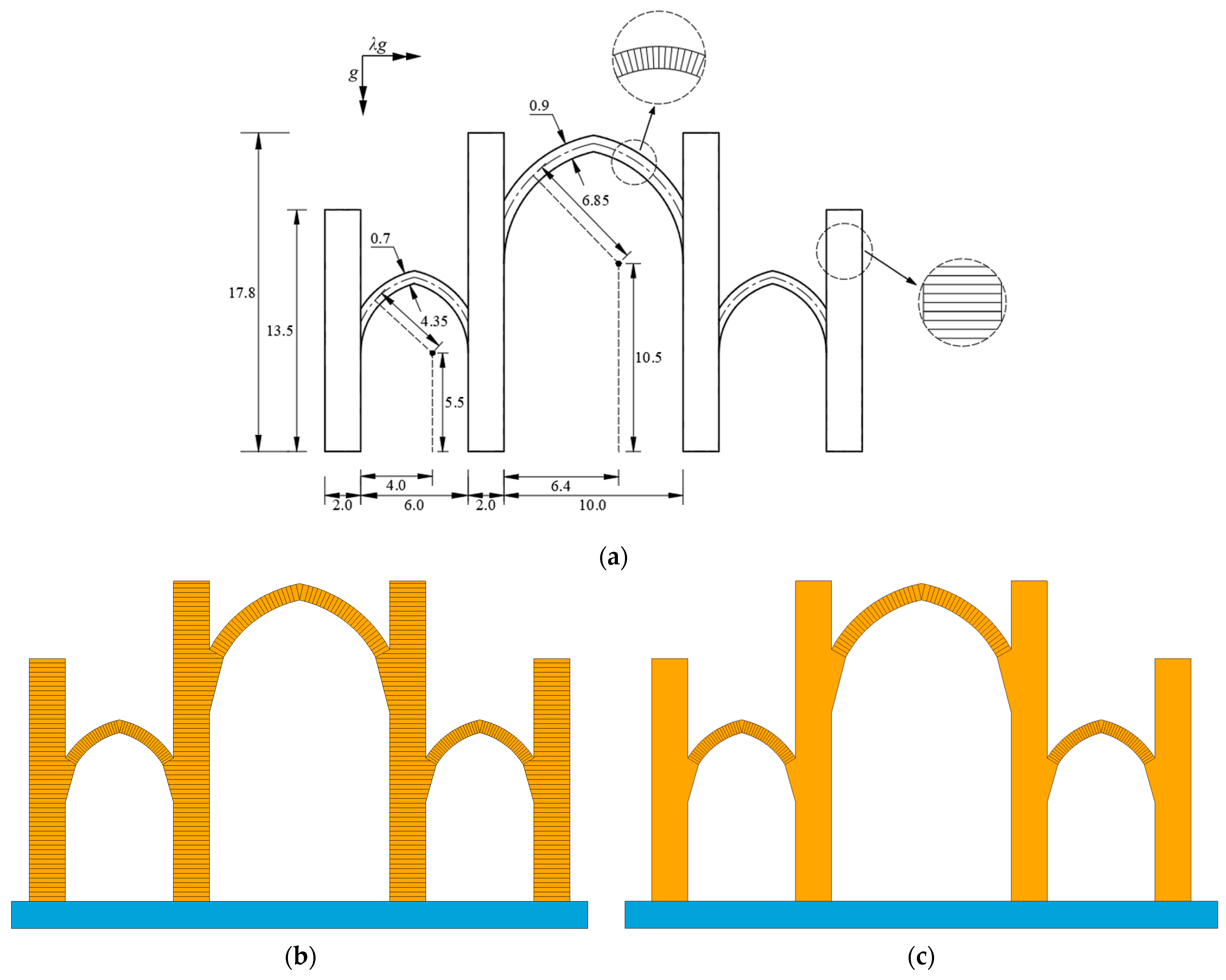
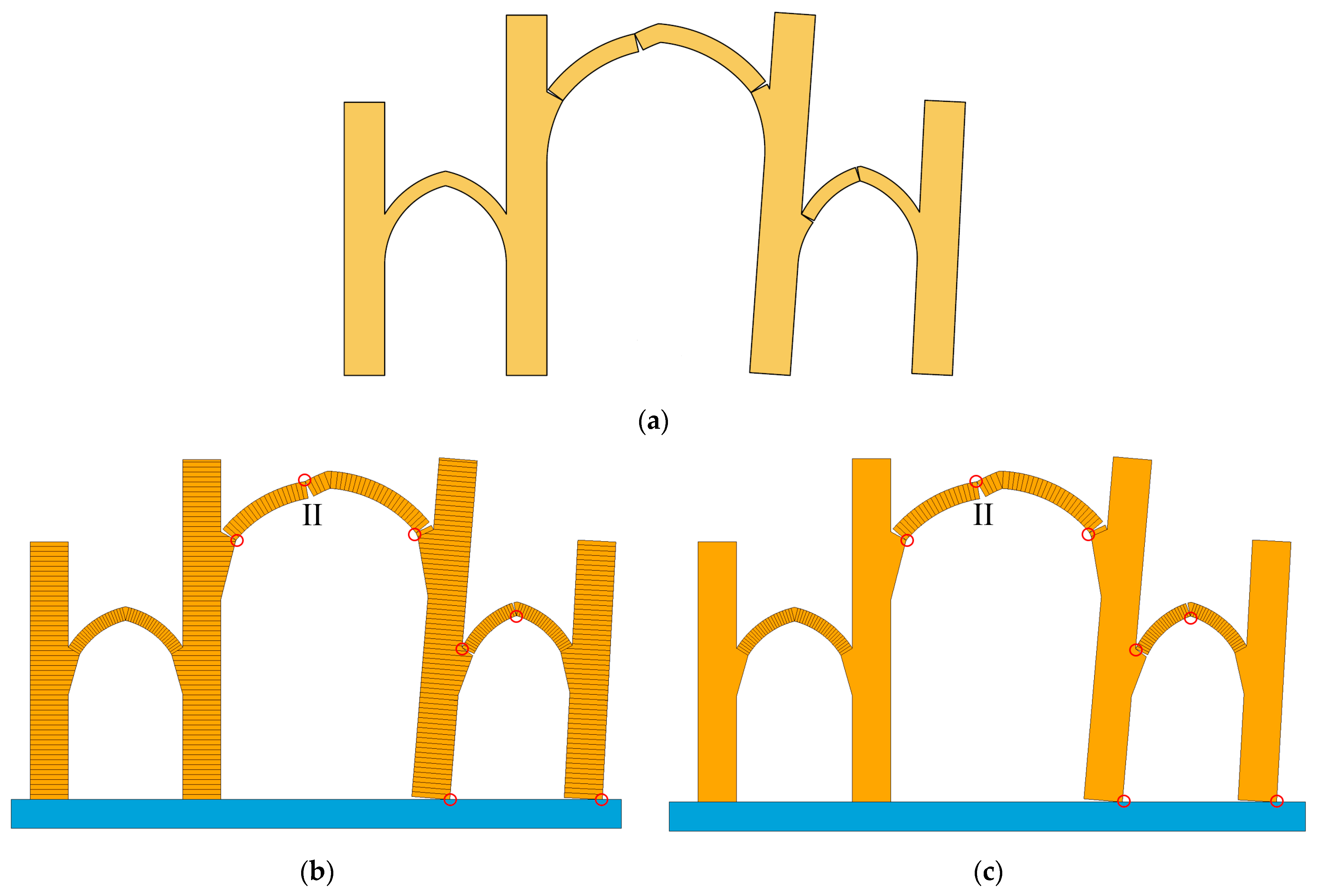
3.3. A Multi-Span Pointed Arch Church

Nodargi and Bisegna [47] investigated the seismic capacity of a multi-span pointed arch church, as shown in Figure 14a, using the approach of limit analysis. It is a three-span buttressed pointed masonry arch structure. Similar to the arch structures in Section 3.1 and Section 3.2, it was subjected to the gravitational acceleration g and a constant horizontal acceleration λg. Various potential failure sections were studied by Nodargi and Bisegna [47], e.g., ‘horizontal’ stereotomy in the buttresses and ‘polar’ stereotomy in the arches, as shown in Figure 14a. Accordingly, the FDEM discretisation is illustrated in Figure 14b, denoted by Scheme A. The buttresses were discretised by horizontal blocks with a height of 0.26 m. The pointed arches were discretised by polar voussoirs with an embrace angle of β = 2°, and a special block was defined at the crown of each arch because of its pointed shape. As a comparison, another discretisation scheme with monolithic buttresses and the same polar voussoirs was also modelled, as shown in Figure 14c, denoted by Scheme B. Similar to the arch structures in Section 3.1 and Section 3.2, only the dry-joint contact and friction between adjacent blocks or voussoirs were considered in the FDEM simulations. The total number of elements is 786 for Scheme A, and 342 for Scheme B. Material properties are as same as in Table 1. In Nodargi and Bisegna [47], ‘a sufficiently large friction angle is assumed to be available’, and the friction coefficient was set to 0.6 in the FDEM simulation, as it is large enough to avoid sliding. The time steps for Scheme A and B were 1.0 × 10⁻⁷ s and 1.0 × 10⁻⁶ s, respectively.
Figure 15 shows the failure modes of the multi-span pointed arch church under gravity and a constant horizontal acceleration from both the FDEM simulations and the limit analysis [46]. It can be observed that they are in excellent agreement. Seven hinges were predicted by both the FDEM simulations and the limit analysis [47], and the locations of these hinges are the same. As shown in Figure 15, the right part of the church inclined to the right, while the left part still stood vertically without noticeable deformation. Three hinges appeared within the arch at the middle span, i.e., one extrados hinge and two intrados hinges; therefore, the arch turned into a three-hinge mechanism. Another two hinges formed in the arch at the right span, i.e., one extrados hinge and one intrados hinge, due to the deformation of the structure. The other two hinges formed at the bottom of two right buttresses due to their rotations under the horizontal acceleration λg.
Table 4 presents the seismic capacity factor λ* of the multi-span pointed arch church from the FDEM simulations and the limit analysis [47]. Apparently, the λ* predicted by the FDEM (both Scheme A and B) is as same as that from the limit analysis, and the difference is only 0.1%. To further examine the differences between Scheme A and B, an extrados hinge, denoted as hinge II in Figure 15b,c, was selected. The time histories of hinge II in the two schemes with λ = 0.0884 are shown in Figure 16. Each curve terminates at the instant when hinge II disappears since the two adjacent voussoirs at the hinge separated completely in the final and fell down.
The computations were run on a Desktop with a 3.70GHz Intel i7-8700K CPU. It was found that the computational time for Scheme A is 2.19 times that for Scheme B. The time-history curves of Scheme A and B are almost coincident with each other before t = 4 s, as the angles of hinge II are very small at the beginning. Subsequently, both angles increased dramatically. The development of hinge II from Scheme B is always slower than that from Scheme A. The surviving time of hinge II from Scheme B is slightly longer (about 3%) than that from Scheme A. Since the difference is very small, and to reduce the computational time, monolithic buttresses can be assumed in the behaviour of this type of arches.

4. Parametric Investigation
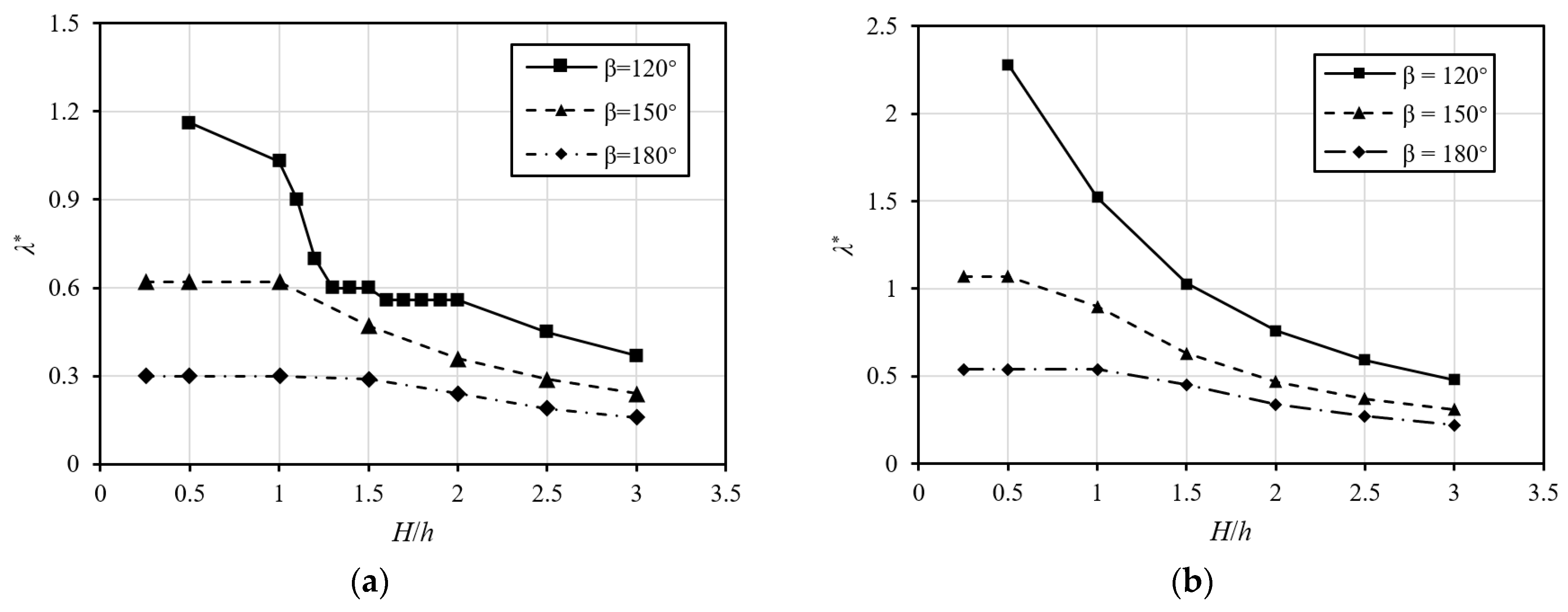
Further simulations were conducted to investigate the effects of geometric characteristics (i.e., H/h and B/Rc) and the friction coefficient μ on the seismic capacity of buttressed masonry arches. Buttressed circular and basket-handle arches were selected as base cases, as shown in Figure 8. Basic geometric parameters of the buttressed arches are: (i) Rc = 1.0 m and t/Rc = 0.2 for both buttressed circular and basket-handle arches; (ii) d/Rc = 0.5 and r/Rc = 0.5 for buttressed basket-handle arches; and (iii) embrace angle β = 120°, 150° and 180° for both buttressed arches. The material properties are as same as in Table 1, and the time step is 1.0 × 10⁻⁶ s.

4.1. H/h

Herein, the ratio of H/h (i.e., the buttress height over the arch height) was investigated. No sliding between voussoirs was considered. For both buttressed arches, the ratio of B/Rc was set to 0.8. The height of buttress H varied from 0.25 m to 3.0 m. The variations of λ* against H/h for both circular and basket-handle buttressed arches were plotted in Figure 17. Overall, the seismic capacity factor λ* declines along with the increasing H/h. A smaller H/h suggests shorter buttresses, corresponding to a lower centre of gravity from the ground; therefore, they are more stable under seismic motions. On the contrary, a larger H/h indicates higher buttresses, which are more apt to overturn under seismic motions. For the buttressed circular arch with β = 120°, a sudden drop of the slope was found between H/h = 1.0 and 1.3, giving rise to the discontinuity on the slope curvature. It is also observed from Figure 17 that the seismic capacity factor λ* deceases significantly along with an increase in embrace angle β. It is reasonable, because for a given H/h and since Rc is constant, a larger β leads to a larger h and, hence, a larger H, which will cause the structure to be more vulnerable to seismic motions, and thus a smaller seismic capacity factor λ* is obtained, and vice versa. It is also suggested that in order to obtain a relatively large λ*, H/h ≤ 1.0 is preferred.

4.2. B/Rc

The influence of the ratio B/Rc (i.e., the buttress width over the radius of the reference circle) on the seismic capacity factor λ* was studied. For both circular and basket-handle buttressed arches, the ratio of H/h was set to 3.0. The width of buttress B up to 1.0 m with a constant step of 0.2 m was studied. Like in Section 4.1, a large friction coefficient µ was set to avoid sliding. The variations of λ* against B/Rc are shown in Figure 18. Pre-examinations on the minimum B/Rc to guarantee the arches are statically stable (i.e., they can stand under gravity) were conducted, and the values are tabulated in Table 5. Any buttress with a smaller B will lead to the collapse of the structure due to the horizontal thrust of the arch induced by gravity. Thus, all the curves in Figure 18 start from the minimum B/Rc that the arch structures are statically stable under gravity.
For both circular and basket-handle buttressed arches, λ* increases monotonically with an increase in B/Rc. Since Rc is constant, the wider the width B, the larger the λ*. For buttressed circular arches, the angle of embrace β has nearly no influence on λ*, as the three curves are quite close to each other. For buttressed basket-handle arches, the same applies except the λ* with β = 180° and B/Rc = 1.0, as a much higher seismic capacity is obtained. The reason is that with the combination of β = 180° and B/Rc = 1.0, the horizontal thrust of the arch is too small to push the buttress down, and the failure of the structure is dominated by hinge rotations of arch voussoirs only, resulting in a much higher λ*.

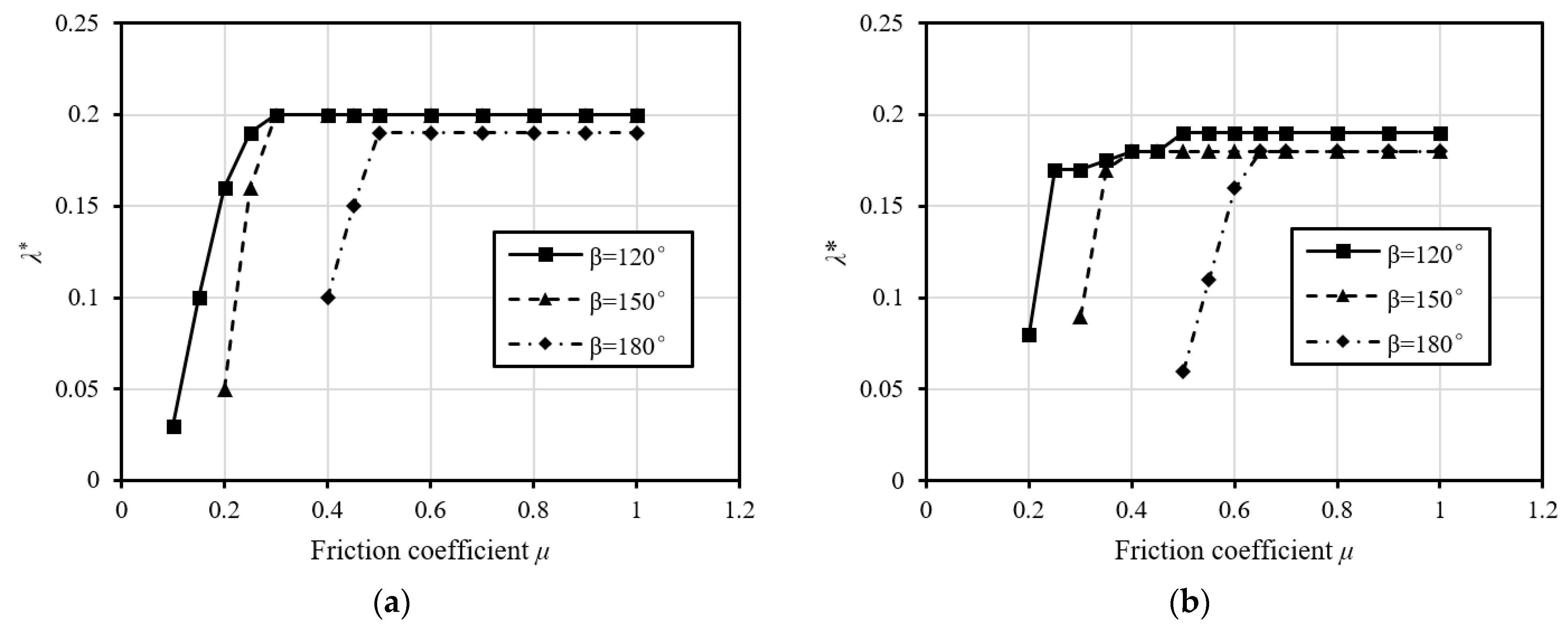
4.3. Friction Coefficient

The influence of friction coefficient μ on the seismic capacity factor λ* was also examined. For both circular and basket-handle buttressed arches, B/Rc was set to 0.8 and H was set to 3.0 m. The friction coefficient μ varied in a range from 0.1 to 1.0, covering most practical engineering materials. The variations of λ* against the friction coefficient μ are illustrated in Figure 19.
As it is shown, for small friction, i.e., μ ≤ 0.5, λ* increases significantly with the increase of μ. However, after μ reaches some thresholds, λ* becomes constant, i.e., it is barely affected by the friction coefficient. This can be attributed to the change of failure modes. If μ is below the threshold, the sliding failure will occur, as shown in Figure 20. Once μ is beyond the threshold, no sliding occurs, and the hinge failure mode dominates. Therefore, careful choice of the material regarding the friction angle needs to be conducted with respect to the choice of the geometry of the arch.

5. Concluding Remarks

In this paper, the combined finite-discrete element method (FDEM) was employed to study the first-order seismic capacity of masonry arch structures subjected to both gravity and a constant horizontal acceleration. The simulation results are validated with data from the existing literature.
In Section 3.1 and Section 3.2, the seismic capacity factors for circular and basket-handle arch structures were predicted by the FDEM, and the results were compared with those from the limit analysis and the UDEC. The FDEM results show that the failures are dominated by a four-hinge failure mechanism should sliding be avoided. Both the seismic capacity factor λ* and the hinge locations were well verified. Supporting the high buttresses, the buttressed arches are much more vulnerable to seismic motions than the corresponding unbuttressed arches. In Section 3.3, the seismic capacity of a multi-span buttressed pointed masonry arch structure was studied with the FDEM, and the obtained results were almost identical to that from the limit analysis, illustrating the reliability and robustness of the FDEM in analysing arch structures with sophisticated shapes.
A parametric investigation on H/h, B/Rc and the friction coefficient μ was conducted in Section 4 to evaluate their effects on λ*. It was assumed that sliding was avoided when H/h and B/Rc varied, and thus the failure was dominated by pure hinging. It was found that λ* decreases with the increase of H/h, while it increases along with an increase in B/Rc. Moreover, a small μ can result in pure sliding or combined sliding-hinging failure, leading to a lower λ*. If sliding occurs, λ* increases along with an increase in μ. When μ reaches some threshold, pure hinging failure dominates and λ* becomes almost constant, indicating that sliding is unlikely to happen any longer. In reality, the load multiplier λ is usually no higher than one. Though only simple investigations have been performed over limited parameters, a more comprehensive parametric study and general conclusions regarding the friction, shape of the arches etc., can be expected in future work.
In general, the FDEM has been proven as a useful and reliable tool in predicting the first-order seismic capacity of masonry arch structures subjected to both gravity and constant horizontal acceleration. Thus, this method can be applied to evaluate the mechanical behaviour of masonry arch structures subjected to more sophisticated loads [48], or with steel-ties between buttresses [49], in future.

Author Contributions

Conceptualisation, X.C.; methodology, X.C.; software, X.C.; validation, W.L.; formal analysis, X.C., W.L. and Y.C.; investigation, W.L. and H.W.; resources, X.C. and Y.C.; writing—original draft preparation, X.C. and W.L.; writing—review and editing, X.C., H.W. and A.H.C.C.; supervision, A.H.C.C.; project administration, X.C.; funding acquisition, X.C. and W.L. All authors have read and agreed to the published version of the manuscript.

Funding

This research was funded by the National Natural Science Foundation of China (grant number 51808368), Qinglan Project of Jiangsu Province of China, and the Postgraduate Research & Practice Innovation Program of Jiangsu Province.

Institutional Review Board Statement

Not applicable.

Informed Consent Statement

Not applicable.

Data Availability Statement

Not applicable.

Acknowledgments

The authors highly appreciate the support of the FDEM program ‘Y’ from A. Munjiza.

Conflicts of Interest

The authors declare no conflict of interest.

References

  1. Heyman, J. The stone skeleton. Int. J. Solids Struct. 1966, 2, 249–279. [Google Scholar] [CrossRef]
  2. Oppenheim, I.J. The masonry arch as a four-link mechanism under base motion. Earthq. Eng. Struct. Dyn. 1992, 21, 1005–1017. [Google Scholar] [CrossRef]
  3. Clemente, P. Introduction to dynamics of stone arches. Earthq. Eng. Struct. Dyn. 1998, 27, 513–522. [Google Scholar] [CrossRef]
  4. Clemente, P.; Raithel, A. The mechanism model in the seismic check of stone arches. In Arch Bridges; CRC Press: Boca Raton, FL, USA, 2020; pp. 123–129. [Google Scholar] [CrossRef]
  5. Baratta, A.; Zuccaro, G.; Binetti, A. Strength capacity of a No-Tension portal arch-frame under combined seismic and ash loads. J. Volcanol. Geotherm. Res. 2004, 133, 369–376. [Google Scholar] [CrossRef]
  6. De Lorenzis, L.; DeJong, M.; Ochsendorf, J. Failure of masonry arches under impulse base motion. Earthq. Eng. Struct. Dyn. 2007, 36, 2119–2136. [Google Scholar] [CrossRef]
  7. Silva, B.; Benetta, M.D.; da Porto, F.; Modena, C. Experimental assessment of in-plane behaviour of three-leaf stone masonry walls. Constr. Build. Mater. 2014, 53, 149–161. [Google Scholar] [CrossRef]
  8. Gaetani, A.; Lourenco, P.; Monti, G.; Moroni, M. Shaking table tests and numerical analyses on a scaled dry-joint arch undergoing windowed sine pulses. Bull. Earthq. Eng. 2017, 15, 4939–4961. [Google Scholar] [CrossRef] [Green Version]
  9. Restrepo-Vélez, L.F.; Magenes, G.; Griffith, M.C. Dry Stone Masonry Walls in Bending—Part I: Static Tests. Int. J. Archit. Herit. 2014, 8, 1–28. [Google Scholar] [CrossRef]
  10. De Luca, A.; Giordano, A.; Mele, E. A simplified procedure for assessing the seismic capacity of masonry arches. Eng. Struct. 2004, 26, 1915–1929. [Google Scholar] [CrossRef]
  11. De Santis, S.; de Felice, G. A fibre beam-based approach for the evaluation of the seismic capacity of masonry arches. Earthq. Eng. Struct. Dyn. 2014, 43, 1661–1681. [Google Scholar] [CrossRef]
  12. Bencardino, F.; Nisticò, M.; Verre, S. Experimental Investigation and Numerical Analysis of Bond Behavior in SRG-Strengthened Masonry Prisms Using UHTSS and Stainless-Steel Fibers. Fibers 2020, 8, 8. [Google Scholar] [CrossRef] [Green Version]
  13. Giordano, A.; Mele, E.; De Luca, A. Modelling of historical masonry structures: Comparison of different approaches through a case study. Eng. Struct. 2002, 24, 1057–1069. [Google Scholar] [CrossRef]
  14. Bićanić, N.; Stirling, C.; Pearce, C.J. Discontinuous modelling of masonry bridges. Comput. Mech. 2003, 31, 60–68. [Google Scholar] [CrossRef]
  15. Tóth, A.R.; Orbán, Z.; Bagi, K. Discrete element analysis of a stone masonry arch. Mech. Res. Commun. 2009, 36, 469–480. [Google Scholar] [CrossRef]
  16. Dimitri, R.; De Lorenzis, L.; Zavarise, G. Numerical study on the dynamic behavior of masonry columns and arches on buttresses with the discrete element method. Eng. Struct. 2011, 33, 3172–3188. [Google Scholar] [CrossRef]
  17. Dimitri, R.; Tornabene, F. A parametric investigation of the seismic capacity for masonry arches and portals of different shapes. Eng. Fail. Anal. 2015, 52, 1–34. [Google Scholar] [CrossRef]
  18. Foti, D.; Vacca, V.; Facchini, I. DEM modeling and experimental analysis of the static behavior of a dry-joints masonry cross vaults. Constr. Build. Mater. 2018, 170, 111–120. [Google Scholar] [CrossRef]
  19. Drei, A.; Milani, G.; Sincraian, G. DEM numerical approach for masonry aqueducts in seismic zone: Two valuable Portuguese examples. Int. J. Mason. Res. Innov. 2017, 2, 1–29. [Google Scholar] [CrossRef]
  20. Forgács, T.; Sarhosis, V.; Bagi, K. Minimum thickness of semi-circular skewed masonry arches. Eng. Struct. 2017, 140, 317–336. [Google Scholar] [CrossRef] [Green Version]
  21. Pulatsu, B.; Erdogmus, E.; Lourenço, P.B. Comparison of in-plane and out-of-plane failure modes of masonry arch bridges using discontinuum analysis. Eng. Struct. 2018, 178, 24–36. [Google Scholar] [CrossRef]
  22. Gonen, S.; Pulatsu, B.; Erdogmus, E.; Karaesmen, E.; Karaesmen, E. Quasi-Static Nonlinear Seismic Assessment of a Fourth Century, A.D. Roman Aqueduct in Istanbul, Turkey. Heritage 2021, 4, 25. [Google Scholar] [CrossRef]
  23. Funari, M.F.; Mehrotra, A.; Lourenço, P.B. A Tool for the Rapid Seismic Assessment of Historic Masonry Structures Based on Limit Analysis Optimisation and Rocking Dynamics. Appl. Sci. 2021, 11, 942. [Google Scholar] [CrossRef]
  24. Munjiza, A. Discrete Elements in Transient Dynamics of Fractured Media. Ph.D. Thesis, University of Wales, Swansea, UK, 1992. [Google Scholar]
  25. Munjiza, A.; Andrews, K.R.F. NBS contact detection algorithm for bodies of similar size. Int. J. Numer. Methods Eng. 1998, 43, 131–149. [Google Scholar] [CrossRef]
  26. Munjiza, A.; Andrews, K.R.F.; White, J.K. Combined single and smeared crack model in combined finite-discrete element analysis. Int. J. Numer. Methods Eng. 1999, 44, 41–57. [Google Scholar] [CrossRef]
  27. Munjiza, A.; John, N.W.M. Mesh size sensitivity of the combined FEM/DEM fracture and fragmentation algorithms. Eng. Fract. Mech. 2002, 69, 281–295. [Google Scholar] [CrossRef]
  28. Munjiza, A. The Combined Finite-Discrete Element Method; John Wiley and Sons: Hoboken, NJ, USA, 2004. [Google Scholar]
  29. Munjiza, A.A.; Knight, E.E.; Rougier, E. Computational Mechanics of Discontinua; John Wiley and Sons: Hoboken, NJ, USA, 2011. [Google Scholar] [CrossRef]
  30. Munjiza, A.; Rougier, E.; Knight, E.E. Large Strain Finite Element Method: A Practical Course; John Wiley and Sons: Hoboken, NJ, USA, 2015. [Google Scholar]
  31. Chen, X.; Chan, A.H. Modelling impact fracture and fragmentation of laminated glass using the combined finite-discrete element method. Int. J. Impact Eng. 2018, 112, 15–29. [Google Scholar] [CrossRef]
  32. Chen, X.; Chan, A. Soft impact responses of laminated glass simulated with the combined finite-discrete element method. Eng. Comput. 2018, 35, 1460–1480. [Google Scholar] [CrossRef]
  33. Munjiza, A.; Lei, Z.; Divic, V.; Peros, B. Fracture and fragmentation of thin shells using the combined finite-discrete element method. Int. J. Numer. Methods Eng. 2013, 95, 478–498. [Google Scholar] [CrossRef]
  34. Chen, X.; Wang, H. Slope Failure of Noncohesive Media Modelled with the Combined Finite–Discrete Element Method. Appl. Sci. 2019, 9, 579. [Google Scholar] [CrossRef] [Green Version]
  35. Deng, P.; Liu, Q.; Huang, X.; Bo, Y.; Liu, Q.; Li, W. Sensitivity analysis of fracture energies for the combined finite-discrete element method (FDEM). Eng. Fract. Mech. 2021, 251, 107793. [Google Scholar] [CrossRef]
  36. Munjiza, A.; Smoljanović, H.; Živaljić, N.; Mihanovic, A.; Divić, V.; Uzelac, I.; Nikolić, Ž.; Balić, I.; Trogrlić, B. Structural applications of the combined finite–discrete element method. Comput. Part. Mech. 2020, 7, 1029–1046. [Google Scholar] [CrossRef]
  37. Smoljanović, H.; Živaljić, N.; Nikolic, Z. A combined finite-discrete element analysis of dry stone masonry structures. Eng. Struct. 2013, 52, 89–100. [Google Scholar] [CrossRef]
  38. Smoljanović, H.; Nikolić, Ž.; Živaljić, N. A finite-discrete element model for dry stone masonry structures strengthened with steel clamps and bolts. Eng. Struct. 2015, 90, 117–129. [Google Scholar] [CrossRef]
  39. Smoljanović, H.; Nikolic, Z.; Živaljić, N. A combined finite–discrete numerical model for analysis of masonry structures. Eng. Fract. Mech. 2015, 136, 1–14. [Google Scholar] [CrossRef]
  40. Smoljanović, H.; Živaljić, N.; Nikolić, Ž.; Munjiza, A. Numerical analysis of 3D dry-stone masonry structures by combined finite-discrete element method. Int. J. Solids Struct. 2018, 136–137, 150–167. [Google Scholar] [CrossRef]
  41. Balić, I.; Zivaljic, N.; Smoljanović, H.; Trogrlic, B. Seismic resistance of dry stone arches under in-plane seismic loading. Struct. Eng. Mech. 2016, 58, 243–257. [Google Scholar] [CrossRef]
  42. Chen, X.; Wang, H.; Chan, A.H.; Agrawal, A.K. Dynamic failure of dry-joint masonry arch structures modelled with the combined finite–discrete element method. Comput. Part. Mech. 2020, 7, 1017–1028. [Google Scholar] [CrossRef]
  43. Chen, X.; Wang, H.; Chan, A.H.C.; Agrawal, A.K.; Cheng, Y. Collapse simulation of masonry arches induced by spreading supports with the combined finite–discrete element method. Comput. Part. Mech. 2020, 8, 721–735. [Google Scholar] [CrossRef]
  44. Chen, X.; Wang, X.; Wang, H.; Agrawal, A.K.; Chan, A.H.; Cheng, Y. Simulating the failure of masonry walls subjected to support settlement with the combined finite-discrete element method. J. Build. Eng. 2021, 43, 102558. [Google Scholar] [CrossRef]
  45. Munjiza, A. Manual for the “y” fem/dem Computer Program. 2000. Available online: https://www.geogroup.utoronto.ca/wp-content/uploads/YManual.pdf (accessed on 10 September 2021).
  46. Lemos, J.V. Discrete element modeling of masonry structures. Int. J. Archit. Herit. 2007, 1, 190–213. [Google Scholar] [CrossRef]
  47. Nodargi, N.A.; Bisegna, P. A unifying computational approach for the lower-bound limit analysis of systems of masonry arches and buttresses. Eng. Struct. 2020, 221, 110999. [Google Scholar] [CrossRef]
  48. Alexakis, H.; Makris, N. Hinging Mechanisms of Masonry Single-Nave Barrel Vaults Subjected to Lateral and Gravity Loads. J. Struct. Eng. 2017, 143, 04017026. [Google Scholar] [CrossRef]
  49. Pulatsu, B.; Erdogmus, E.; Bretas, E.M.; Lourenço, P.B. In-Plane Static Response of Dry-Joint Masonry Arch-Pier Structures. In Proceedings of the AEI 2019: Integrated Building Solutions—The National Agenda AEI 2019 Conference, Tysons, VA, USA, 3–6 April 2019; pp. 240–248. [Google Scholar]
Figure 1. Discretisation of arch voussoirs.
Applsci 11 08725 g001
Figure 2. Contact forces in the 2D FDEM.
Applsci 11 08725 g002
Figure 3. Geometry of arches: (a) circular arch; (b) basket-handle arch.
Applsci 11 08725 g003
Figure 4. Mesh configurations: (a) circular arch with β = 150° (N = 36); (b) circular arch with β = 180° (N = 34); (c) basket-handle arch with β = 150° (N = 106); (d) basket-handle arch with β = 180° (N = 46).
Applsci 11 08725 g004
Figure 5. Failure process of the circular arch with β = 180°: (a) t = 0.5 s; (b) t = 0.65 s; (c) t = 0.85 s; (d) t = 0.95 s.
Applsci 11 08725 g005
Figure 6. Failure modes of circular arches.
Applsci 11 08725 g006
Figure 7. Failure modes of basket-handle arches.
Applsci 11 08725 g007
Figure 8. Geometry of buttressed arches (after [17]): (a) circular arch; (b) basket-handle arch.
Applsci 11 08725 g008
Figure 9. Mesh configurations of buttressed arches.
Applsci 11 08725 g009aApplsci 11 08725 g009b
Figure 10. Failure process of the buttressed basket-handle arch with β = 180°: (a) t = 1.0 s; (b) t = 1.3 s; (c) t = 1.5 s.
Applsci 11 08725 g010
Figure 11. Failure modes of buttressed circular masonry arches.
Applsci 11 08725 g011
Figure 12. Failure modes of buttressed basket-handle masonry arches.
Applsci 11 08725 g012
Figure 13. Influences of Young’s modulus of masonry blocks on the seismic capacity.
Applsci 11 08725 g013
Figure 14. The multi-span pointed arch church: (a) geometry (unit: m); (b) FDEM discretisation of Scheme A; (c) FDEM discretisation of Scheme B.
Applsci 11 08725 g014
Figure 15. Failure modes of the multi-span pointed arch church: (a) limit analysis [47]; (b) FDEM result of Scheme A; (c) FDEM result of Scheme B.
Applsci 11 08725 g015
Figure 16. Time histories of hinge II from the FDEM simulations.
Applsci 11 08725 g016
Figure 17. Variation of λ* against H/h: (a) circular arch; (b) basket-handle arch.
Applsci 11 08725 g017
Figure 18. Variation of λ* against B/Rc: (a) circular arch; (b) basket-handle arch.
Applsci 11 08725 g018
Figure 19. Variation of λ* against μ: (a) circular arch; (b) basket-handle arch.
Applsci 11 08725 g019
Figure 20. Sliding failures: (a) pure sliding, buttressed circular arch, β = 120°, μ = 0.2, λ = 0.16; (b) combined hinging and sliding, buttressed basket-handle arch, β = 180°, μ = 0.6, λ = 0.16.
Applsci 11 08725 g020
Table 1. Material properties of arches.
Young’s Modulus (GPa)Poisson’s RatioDensity (kg/m3)
40.00.22000.0
Table 2. λ * of circular and basket-handle arches without buttresses.
Embrace Angle β (°)λ *
FDEM/e (%)Limit Analysis [17]UDEC [17]/e (%)
Circular1201.14/10.21.271.28/0.79
1500.618/0.320.620.64/3.23
1800.294/1.380.290.31/6.90
Basket-handle1202.10/10.62.352.38/1.28
1501.067/0.661.061.10/3.77
1800.539/0.190.540.56/3.70
Table 3. λ * of buttressed circular and basket-handle masonry arches.
Embrace Angle β (°)λ *
FDEM/e (%)Limit Analysis [17]UDEC [17]/e (%)
Circular1200.166/3.750.160.17/6.25
1500.178/1.110.180.18/0.00
1800.188/1.050.190.21/10.53
Basket-handle1200.150/7.140.140.15/7.14
1500.160/6.670.150.16/6.67
1800.174/8.750.160.17/6.25
Table 4. Seismic capacity of the multi-span pointed arch structure.
FDEMLimit Analysis [47]
Scheme AScheme B
λ*/e (%)0.0883/0.10.0883/0.10.0882
Table 5. Minimum statically stable B/Rc.
Embrace Angle βB/Rc
Circular120°0.38
150°0.37
180°0.37
Basket-handle120°0.43
150°0.43
180°0.43
Publisher’s Note: MDPI stays neutral with regard to jurisdictional claims in published maps and institutional affiliations.

