Article

A Novel Approach to Calculating the Transmission Accuracy of a Cycloid-Pin Gear Pair Based on Error Tooth Surfaces

1
State Key Laboratory of Mechanical Transmission, Chongqing University, 174 Shazhengjie, Shapingba, Chongqing 400044, China
2
Department of Mechanical Engineering, Politecnico di Milano, Via G. La Masa 1, 20156 Milan, Italy
*
Author to whom correspondence should be addressed.
Appl. Sci. 2021, 11(18), 8671; https://doi.org/10.3390/app11188671
Submission received: 16 August 2021 / Revised: 14 September 2021 / Accepted: 15 September 2021 / Published: 17 September 2021
(This article belongs to the Section Mechanical Engineering)

Abstract

:
Transmission error (TE) and backlash are important parameters used to evaluate the transmission accuracy of cycloid-pin drives. Existing calculation methods are mostly based on two-dimensional tooth profile models, and these methods ignore the influence of some abnormal meshing phenomena caused by profile modifications (PMs), manufacturing errors (MEs), and assembly errors (AEs), such as the instantaneous mesh-apart of tooth pairs and the eccentric load on the tooth surface. To fill this gap, a novel approach to accurately calculating the TE and backlash of a cycloid-pin gear pair based on the error tooth surfaces is proposed, and its feasibility and effectiveness are validated by comparison with the theoretical analyses and the results from the literature. Based on this, the effects of the PMs, MEs, and AEs on the transmission accuracy are studied, which will be helpful in optimizing the tooth profile design of a cycloid gear and the tolerance allocation during the installation of a gear pair. The proposed method is also expected to provide accurate error excitation data for the dynamic analysis of cycloid-pin drives.

1. Introduction

Cycloid-pin drives have the advantages of high transmission ratios, transmission accuracy, torsional stiffness, transmission efficiency, and compact structures. Cycloid-pin drives have been widely used in high-precision equipment, such as industrial robots, machine tools, and assembly and conveying equipment. This type of equipment usually requires frequent forward and reverse rotation during work and has high position accuracy requirements, which mainly depend on the transmission error (TE) and backlash of cycloid-pin drives. Establishing a calculation method for the TE and backlash, while comprehensively considering the effects of profile modifications (PMs), manufacturing errors (MEs), and assembly errors (AEs), is of great significance for optimizing the tooth profile design of a cycloid gear and the tolerance allocation during the installation of a gear pair. It can also provide the error excitation data for the accurate dynamic analysis of cycloid drives.
The cycloid-pin gear reducer was initially introduced by Botsiber and Kingston [1] and Pollitt [2]. Then a series of novel cycloidal reducers was presented to obtain higher rigidity [3,4,5] or more compact structure [6,7,
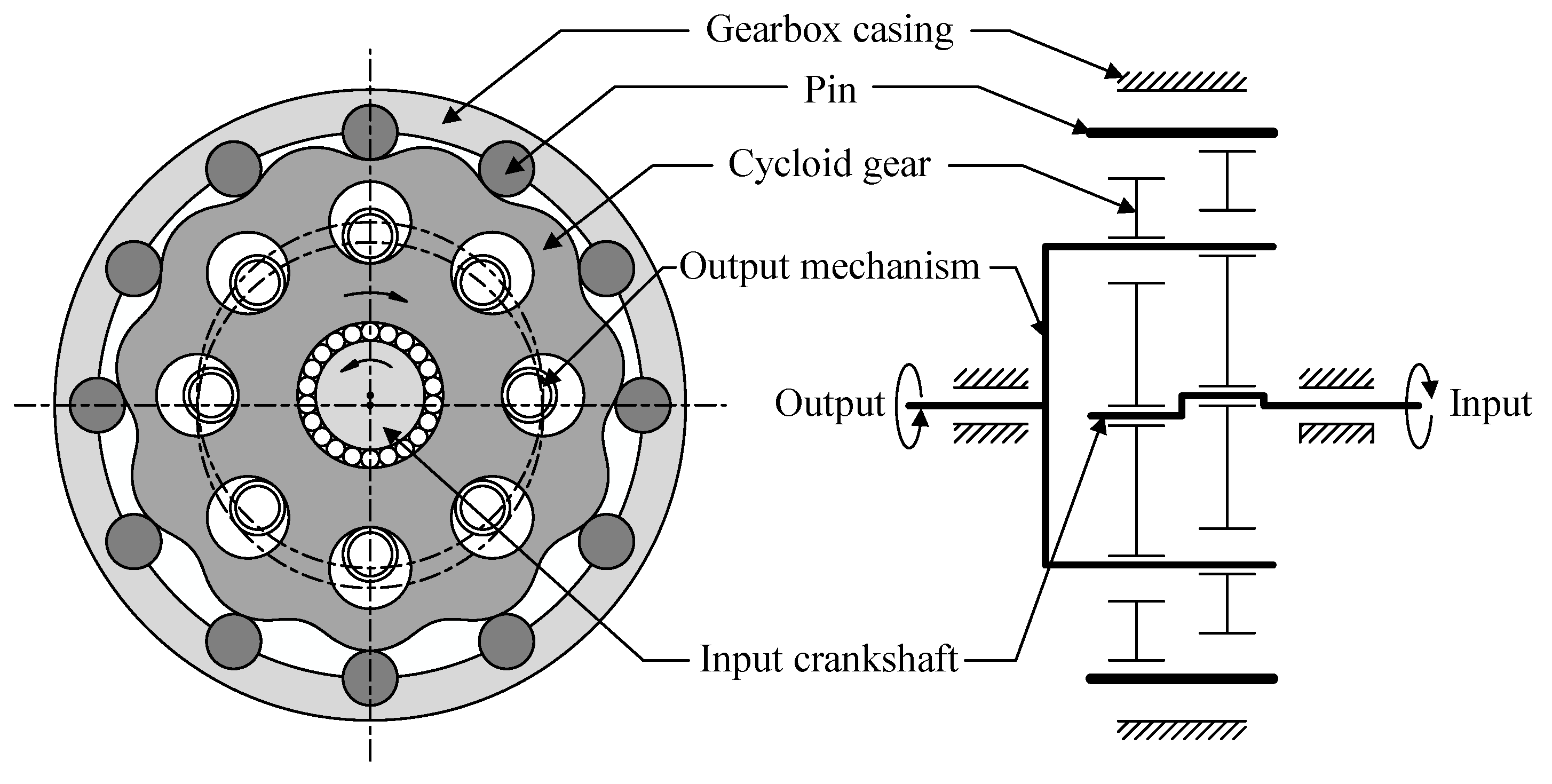
8]. A typical structure of cycloid-pin gear reducer is shown in Figure 1, which includes a gearbox casing, an input crankshaft, an output mechanism, two cycloid gears, and pins. During the transmission process, the cycloid gear not only rotates counterclockwise with the input crankshaft around the center of the pin center circle, but it also rotates clockwise around its own center to drive the output mechanism to rotate. For each cycloid gear, ideally, all the pins are in contact with it during the transmission process, and half of the pins transmit the load. Due to the multi-tooth meshing characteristics of cycloid-pin drives, these drives are more sensitive to MEs and AEs, and the tooth interference can easily occur in the transmission process. However, MEs and AEs are inevitable in practice, and these errors will change the number of contact teeth, the load distribution between teeth, the torsional stiffness, and other meshing characteristics, thereby adversely affecting the TE and backlash of cycloid-pin drives. In the published works, Blanche and Yang [9,10] first studied the influence of manufacturing tolerances on torque ripples and backlash, but only the profile tolerance was considered in their analysis model. Lin et al. [11] investigated the influence of the manufacturing tolerance on the TE of a cycloidal gear reducer, and more types of manufacturing tolerance were considered in their analysis model, such as the pin radius error, pin position error, tooth profile error, and pitch error in the tooth profile. Li et al. [12] also studied the effects of tooth profile and pitch errors on the TE and backlash of a cycloidal-pin gear, achieving the effective pre-control of the tooth profile and the meshing contact performance. Li et al. [13] investigated the influence of the clearance and eccentricity errors on the gear ratio, transmission error, bearing load, and contact stress of a cycloid reducer. Han and Guo [14] analyzed the global sensitivity of the transmission accuracy for cycloid-pin drives with the Sobol method in comprehensive consideration of the nonlinear and uncertainty factors, such as the MEs, AEs, and bearing clearances. Ivanović et al. [15] studied the effects of the profile geometrical parameters of a trochoidal gear on the gearing process, clearance height change, and pulsation of a drive moment. Hidaka et al. [16,17] analyzed the TE of K-H-V-type planetary gears with cycloid gears based on a two-dimensional model with twenty degrees of freedom. Meng et al. [18] analyzed the effects of the kinematics parameters on the transmission performance of a 2K-H pin-cycloid planetary mechanism based on a static analysis of the actual meshing transmission process between the gear pairs considering friction. In the above studies, the analysis models of the TE and backlash were mostly established in a two-dimensional plane, and the MEs that were considered were mostly along the tooth profile direction, while the MEs along the tooth-width direction were rarely involved. Additionally, the studies of the effects of the AEs on the TE and backlash were incomplete. Only the influence of the eccentricity errors was analyzed, while the effects of misalignment deviations were not considered.
To avoid the tooth interference caused by MEs and AEs and obtain better lubrication conditions, profile modifications (PMs) are necessary for cycloid-pin drives. This also has a non-negligible effect on the TE and backlash of cycloid-pin drives. Sun et al. [5] proposed a compound modification method combining negative isometric and negative offset modification to reduce the influence of PMs on backlash. Li et al. [19] proposed a novel method for PMs to improve the motion accuracy and modification quality that comprehensively considered the effects of the backlash, pressure angle distribution, and tooth tip and root clearance. In addition, many scholars have studied the torsional stiffness, transmission efficiency, load analysis, and optimization design methods of cycloid-pin drives. In terms of torsional stiffness, Kumar et al. [20] proposed a new method for estimating the elastic torsional compliance of single-stage cycloidal drives based on static experimental results. Li et al. [21] proposed a new method to calculate the mesh stiffness of a cycloid-pin gear pair considering the effects of PMs and the eccentricity error based on the unloaded tooth contact analysis and the nonlinear Hertzian contact theory. Liu et al. [22] calculated the torsional stiffness of a cycloid gear using the Majumdar–Bhushan contact model and the finite element method. In terms of transmission efficiency, Garlo et al. [23] proposed a simplified procedure to calculate the force distribution on cycloid drive elements, the power losses, and the theoretical mechanical efficiency. Mackic et al. [24] analyzed the effects of design parameters on the efficiency of a cycloidal gear drive, such as the pitch radius and number of housing rollers. Sensinger [25] derived the efficiency equations for cycloid drives using Del Castillo’s framework. In terms of load analysis, Malhotra and Parameswaran [26] investigated the influence of the design parameters of a cycloid speed reducer on forces and contact stress. Xu et al. [27] proposed a method for analyzing the contact dynamics of the multi-tooth meshing in a cycloid-pin drive considering the effect of the turning-arm cylindrical roller bearing. In terms of the optimization design methods of cycloid-pin drives, Wang et al. [28] proposed an optimization design method for cycloid drives with the goal of maximizing efficiency and minimizing volume based on a genetic algorithm. Wang et al. [29] proposed a multi-objective optimal model for cycloid-pin drives in which the objective functions were used for the bending stress of the pins, the force of the crank bearing, and the reducer volume. With the development of computing technology in recent years, the finite element method has been widely used in the research of cycloid-pin drives. For example, Li [30] carried out loaded gear contact analysis and strength calculations for trochoidal gear reducers based on a mechanics model and a finite element method. Tran et al. [31] studied the lost motion of a cycloid reducer using a combined finite element and kinematic analysis and concluded that the backlash of a cycloid reducer was not only related to the torsional stiffness but also to the tolerance. However, the multi-tooth meshing characteristics of cycloid-pin drives often lead to a huge finite element model, low computational efficiency, and expensive computational costs.
Cycloid-pin gear pairs are the key components of the cycloid-pin drives. To accurately calculate the TE and backlash of a cycloid-pin gear pair, a novel calculation method based on error tooth surfaces is presented that has the ability to consider the influence of some abnormal meshing phenomena caused by PMs, MEs, and AEs on the TE and backlash, such as the instantaneous mesh-apart of tooth pairs and the eccentric load on the tooth surface. In this paper, the first section reviews the research on the TE, backlash, and other meshing characteristics of cycloid-pin drives. An error tooth surface model of a cycloid gear and pin considering the PMs, MEs, and AEs is established in Section 2. Section 3 describes in detail the principle of the novel calculation method of TE and backlash. The presented method is verified by comparing the results with the theoretical analysis results and the literature, as delineated in Section 4. Section 5 describes the investigation of the effects of the PMs, MEs, and AEs on the TE and backlash of the cycloid-pin gear pair through a series of simulation cases, and the analysis of the abnormal meshing phenomena caused by these errors in the transmission process. Section 6 presents the conclusions of this study, and the significance of the proposed method is summarized.

2. Error Tooth Surface Model of Cycloid Gear and Pin

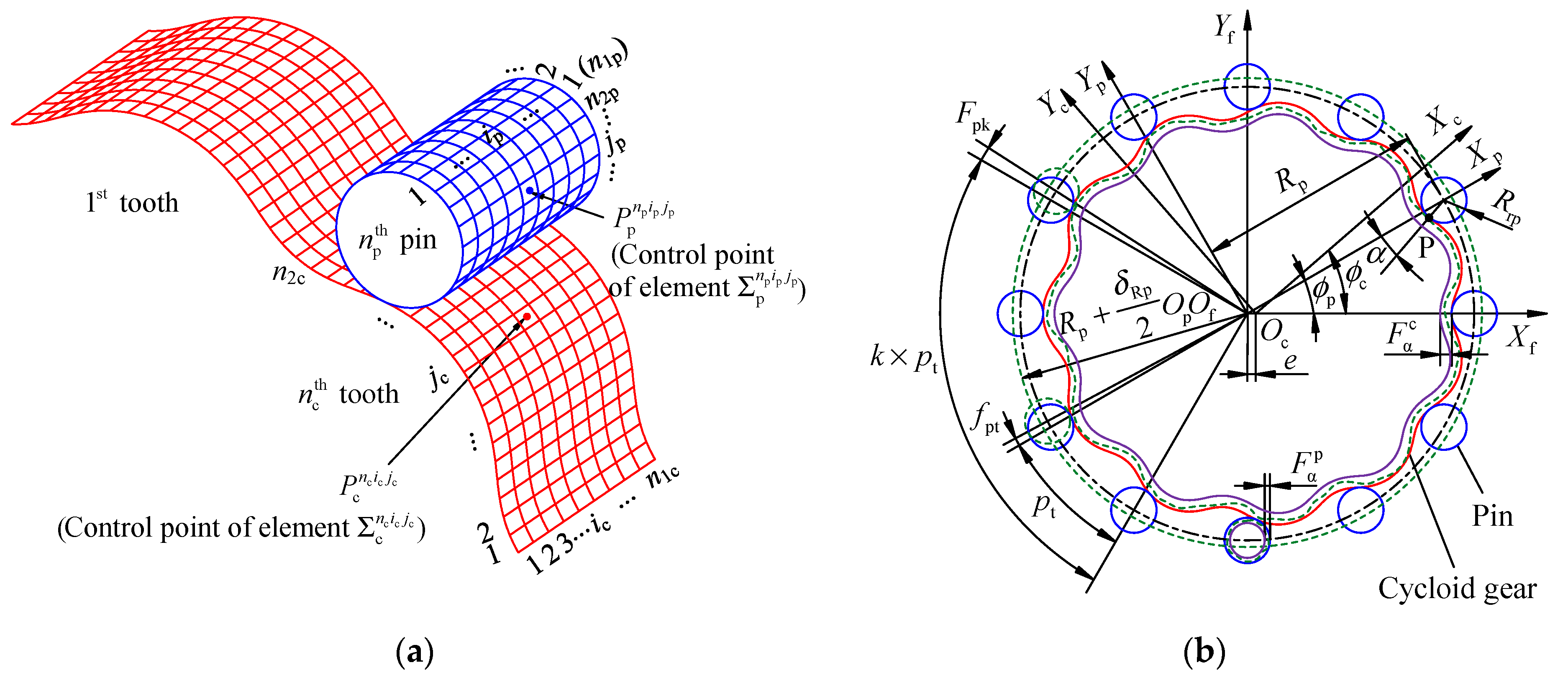
A reasonable tooth surface model comprehensively considering PMs, MEs, and AEs is the key to accurately calculating the TE and backlash of a cycloid-pin gear pair. In this study, the tooth surfaces of a cycloid gear and pin are discretized into multiple elements with the same size, as shown in Figure 2a. The surfaces of the n c th cycloid tooth and the n p th pin are discretized into n1c and n1p elements along the tooth width, and into n2c and n2p elements along the tooth profile. ic and ip are the indices of the discrete elements along the tooth width, and jc and jp are the indices of the discrete elements along the tooth profile. Each discrete element on the tooth surface is approximately represented as a cylindrical surface within a certain coordinate range and each discrete element has a corresponding control point defined at the center of the element. The radius of the equivalent cylindrical surface is equal to the radius of curvature at the element control point, and its axis is parallel to the axis of the cycloid gear and pin. Once the coordinates, radius of curvature, and normal vector at the element control point and the axis direction vector of the approximate cylinder corresponding to the discrete element are determined, the equivalent cylindrical surface is unique.
The coordinate systems for generating the tooth surfaces of a cycloid gear and pin with PMs and MEs are shown in Figure 2b. The coordinate systems XfOfYf, XcOcYc, and XpOpYp are rigidly connected to the frame, cycloid gear, and pin, respectively. Rrp and Rp are the radii of the pin and the pin center circle, respectively. e is the eccentric distance between Oc and Of. The rotation angles of XcOcYc and XpOpYp are defined as ϕc and ϕp, respectively, and they have the relationship ϕc/ϕp = zp/zc, where zp and zc represent the number of pins and the teeth of cycloid gear, respectively. α is the angle parameter at the contact point P. The red and blue solid lines are the theoretical tooth profile of the cycloid gear and pin, respectively. Based on the previous publication [5], the PMs of a cycloid gear can be divided into four types, namely, isometric modification, offset modification, angle rotation modification, and compound modification. Since the angle rotation modification cannot produce a gap between the tooth tip and root of a cycloid gear and the pins, it cannot be used alone, and is not considered in this study. The tooth surface of a cycloid gear with the isometric modification and the offset modification can be obtained by changing Rrp and Rp, and the tooth surface with the compound modification can be obtained by changing them at the same time. Thus, the coordinates of the element control point of a cycloid gear considering PMs are given as follows:
[ X c 1 n c i c j c Y c 1 n c i c j c Z c 1 n c i c j c ] = [ ( R p + Δ R p ) cos ( ϕ p n c i c j c / z c ) ( R rp + Δ R rp ) cos ( α ϕ p n c i c j c / z c ) e cos ( z p ϕ p n c i c j c / z c ) ( R p + Δ R p ) sin ( ϕ p n c i c j c / z c ) + ( R rp + Δ R rp ) sin ( α ϕ p n c i c j c / z c ) e sin ( z p ϕ p n c i c j c / z c ) B c B c ( i c 1 / 2 ) / n 1 c ] ,
where the superscripts nc, ic, and jc indicate the ic × jc element on the n c th tooth of cycloid gear, and the subscript c1 represents the tooth surface of a cycloid gear with PMs, and Bc is the tooth width of a cycloid gear, and ΔRrp and ΔRp are the modification amounts of the isometric modification and the offset modification, respectively. α can be calculated with:
α = arctan z p e sin ( ϕ p n c i c j c ) R p + Δ R p z p e cos ( ϕ p n c i c j c ) .
It is worth noting that the arc length of the cycloid tooth profile is a nonlinear function of ϕp. If the tooth surface of the cycloid gear is discrete with the same ϕp in the tooth profile direction, the arc lengths between the adjacent element control points along the tooth profile are not equal, and the element control points are concentrated on the convex tooth surface. To improve the calculation accuracy of the TE and backlash, the tooth surface of the cycloid gear along the tooth profile direction is discrete with the same arc length. The arc length corresponding to different ϕp can be obtained with numerical integration. Then ϕp is fitted as a polynomial function of the arc length. It is assumed that N is the order of the polynomial function, and AN, AN−1, ⋯, A1, A0 are the coefficients of the polynomial function. The ϕ p n c i c j c in Equation (1) can be calculated with:
ϕ p n c i c j c = A N ( S c ( j c 1 / 2 ) n 2 c ) N + A N 1 ( S c ( j c 1 / 2 ) n 2 c ) N 1 + + A 1 ( S c ( j c 1 / 2 ) n 2 c ) + A 0 ,
where Sc is the total arc length of a single tooth profile of the cycloid gear.
In Figure 2b, the green dashed line indicates the error tooth profiles of a cycloid gear and pin with MEs. The MEs of the pin considered in this study include the total profile deviation ( F α p ), single pitch deviation (fpt), total cumulative pitch deviation (Fp), and pin center circle diameter deviation (δRp). pt is the single pitch of a pin. Since the pitch deviations of the cycloid gear and pin have similar effects on the TE and backlash, the pitch deviation of the cycloid gear can be equivalently converted to the pins, and only the total profile deviation of the cycloid gear ( F α c ) is considered in this study. The error profile of the cycloid gear is located between the theoretical tooth profile and the virtual tooth profile (see the solid purple line in Figure 2b) defined by the total profile deviation ( F α c ). According to gear conjugate theory and coordinate transformation principle, the coordinates of the element control points of the cycloid gear and pin considering PMs and MEs are given as:
[ X c 2 n c i c j c Y c 2 n c i c j c Z c 2 n c i c j c ] = [ ( R p + Δ R p ) cos ( ϕ p n c i c j c / z c ) ( R rp + Δ R rp + δ n c i c j c ) cos ( α ϕ p n c i c j c / z c ) e cos ( z p ϕ p n c i c j c / z c ) ( R p + Δ R p ) sin ( ϕ p n c i c j c / z c ) + ( R rp + Δ R rp + δ n c i c j c ) sin ( α ϕ p n c i c j c / z c ) e sin ( z p ϕ p n c i c j c / z c ) B c B c ( i c 1 / 2 ) / n 1 c ] ,
[ X p n p i p j p Y p n p i p j p Z p n p i p j p ] = [ ( R p + δ Rp / 2 ) cos [ 2 π ( n p 1 ) / z p + z = 1 n p f pt z / ( R p + δ Rp / 2 ) ] + ( R rp + δ n p i p j p ) cos [ 2 π ( j p 1 / 2 ) / n 2 p ] ( R p + δ Rp / 2 ) sin [ 2 π ( n p 1 ) / z p + z = 1 n p f pt z / ( R p + δ Rp / 2 ) ] + ( R rp + δ n p i p j p ) sin [ 2 π ( j p 1 / 2 ) / n 2 p ] B p B p ( i p 1 / 2 ) / n 1 p ] ,
where the subscript c2 in Equation (4) represents the tooth surfaces of a cycloid gear with PMs and MEs, and the superscripts np, ip, and jp indicate the ip × jp element on the n p th pin, and δ n c i c j c and δ n p i p j p are the profile deviation of each element of the cycloid gear and pin, respectively. Bp is the tooth width of a pin, and f pt z is the single pitch deviation of the zth pin. It is known that the MEs of a gear are distributed according to a probability in their tolerance ranges. Thus, δ n c i c j c , δ n p i p j p , f pt z , and δRp can be obtained through different probability distribution functions according to their tolerance ranges. Additionally, the pitch deviation of the pin ( f pt z ) must also meet the tolerance range of the total cumulative pitch deviation (
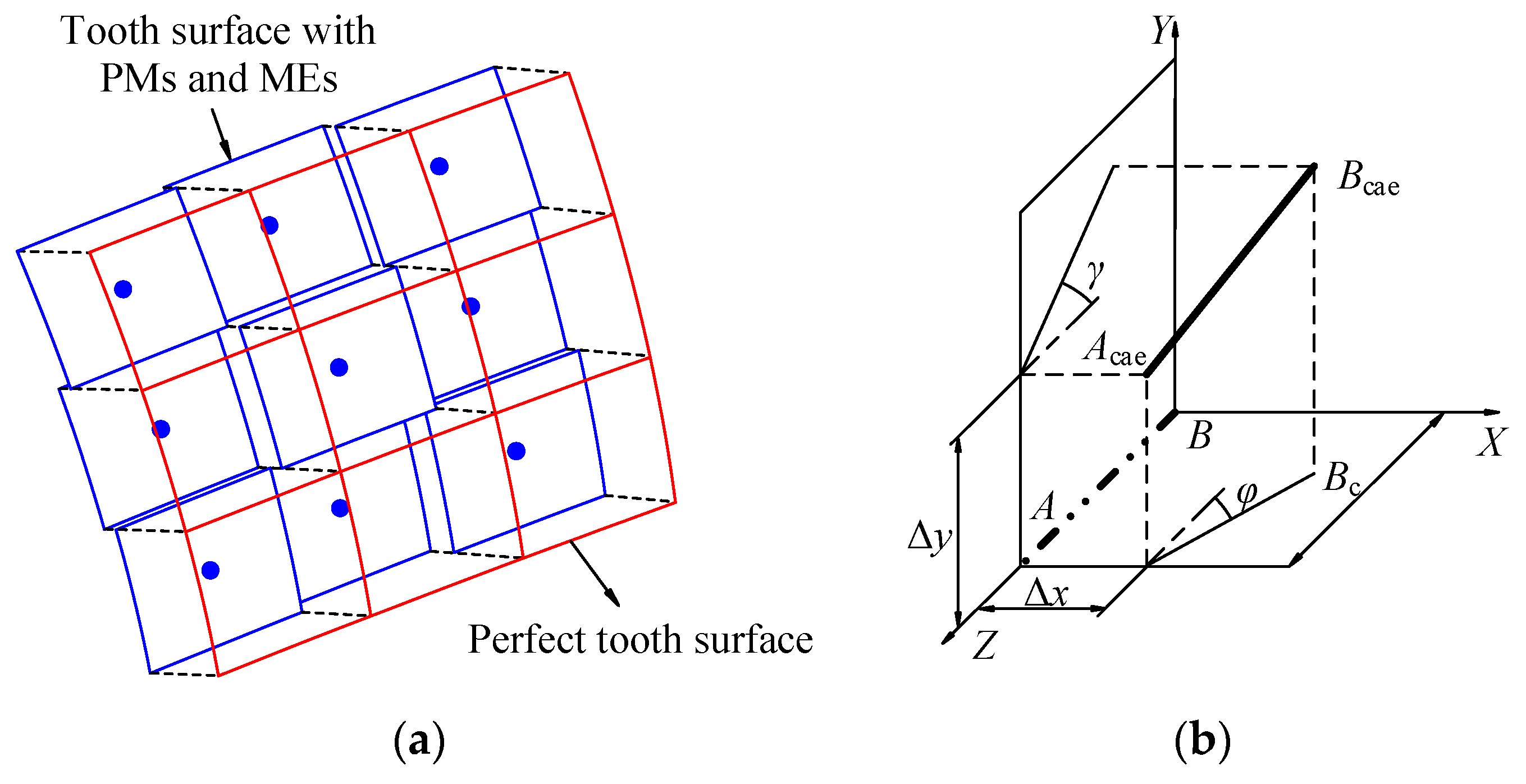
Fp). The part of the tooth surface of cycloid gear considering PMs and MEs is shown in Figure 3a, and it is composed of multiple discrete elements with different distances from the perfect tooth surface. Similarly, the tooth surface of the pin considering MEs has the same characteristics.
Figure 3b shows the definition of the AEs in this study. The AEs of cycloid gear and pin are equivalently transferred to the axis position of the cycloid gear to simplify the error tooth surface model. AB is the theoretical axis position of the cycloid gear without AEs, and AcaeBcae is the new axis position of the cycloid gear when the AEs are considered. The AEs are indicated by four parameters, where Δx and Δy are called the center distance deviations, and φ and γ are the misalignment deviations on the XBZ-plane and the YBZ-plane, respectively. The different AEs can be obtained using different combinations of the above four parameters. The coordinates of the element control point ic × jc on the n c th tooth surface of the cycloid gear considering AEs are given as follows:
[ X c n c i c j c Y c n c i c j c Z c n c i c j c 1 ] T = M ae [ X c 2 n c i c j c Y c 2 n c i c j c Z c 2 n c i c j c 1 ] T ,
where Mae is the coordinate transformation matrix considering AEs, which is given as follows:
Μ ae = [ 1 0 ( 1 sin γ ) tan φ sin φ Δ x + B c [ sin φ ( 1 sin γ ) tan φ ] 0 1 sin γ / cos φ Δ y + B c sin γ / cos φ 0 0 sin γ cos φ 1 B c ( cos φ + 1 sin γ ) 0 0 0 1 ] .
To summarize, the coordinates of each element control point of the cycloid gear and pin considering PMs, MEs, and AEs have been obtained. Additionally, the radius of curvature and the normal vector at each control point, as well as the axis direction vector of the approximate cylinder corresponding to each element are also necessary to uniquely determine the position and size of the equivalent cylindrical surface corresponding to each element. The radii of curvature at each element control point of the cycloid gear and pin are given as follows:
ρ c n c i c j c = [ e 2 z p 2 + ( R p + Δ R p ) 2 2 e z p ( R p + Δ R p ) cos ( ϕ p n c i c j c ) ] 3 / 2 e 2 z p 3 + ( R p + Δ R p ) 2 e z p ( 1 + z p ) ( R p + Δ R p ) cos ( ϕ p n c i c j c ) ( R rp + Δ R rp + δ n c i c j c ) ,
ρ p n p i p j p = R rp + δ n p i p j p ,
where ρ c n c i c j c can be negative (−) for a concave surface and positive (+) for a convex surface.
The normal vectors at each element control point of the cycloid gear and pin are respectively given as follows:
n c n c i c j c = M ae [ d X c 1 n c i c j c / d ϕ p n c i c j c d Y c 1 n c i c j c / d ϕ p n c i c j c 0 1 ] T ,
n p n p i p j p = [ cos ( 2 π ( j p 1 / 2 ) / n 2 p ) sin ( 2 π ( j p 1 / 2 ) / n 2 p ) 0 1 ] T .
The axis direction vectors of the approximate cylinder of each element of the cycloid gear and pin are given as follows:
V c n c i c j c = [ ( 1 sin γ ) tan φ sin φ sin γ / cos φ sin γ cos φ 1 ] T ,
V p n p i p j p = [ 0 0 1 1 ] T .

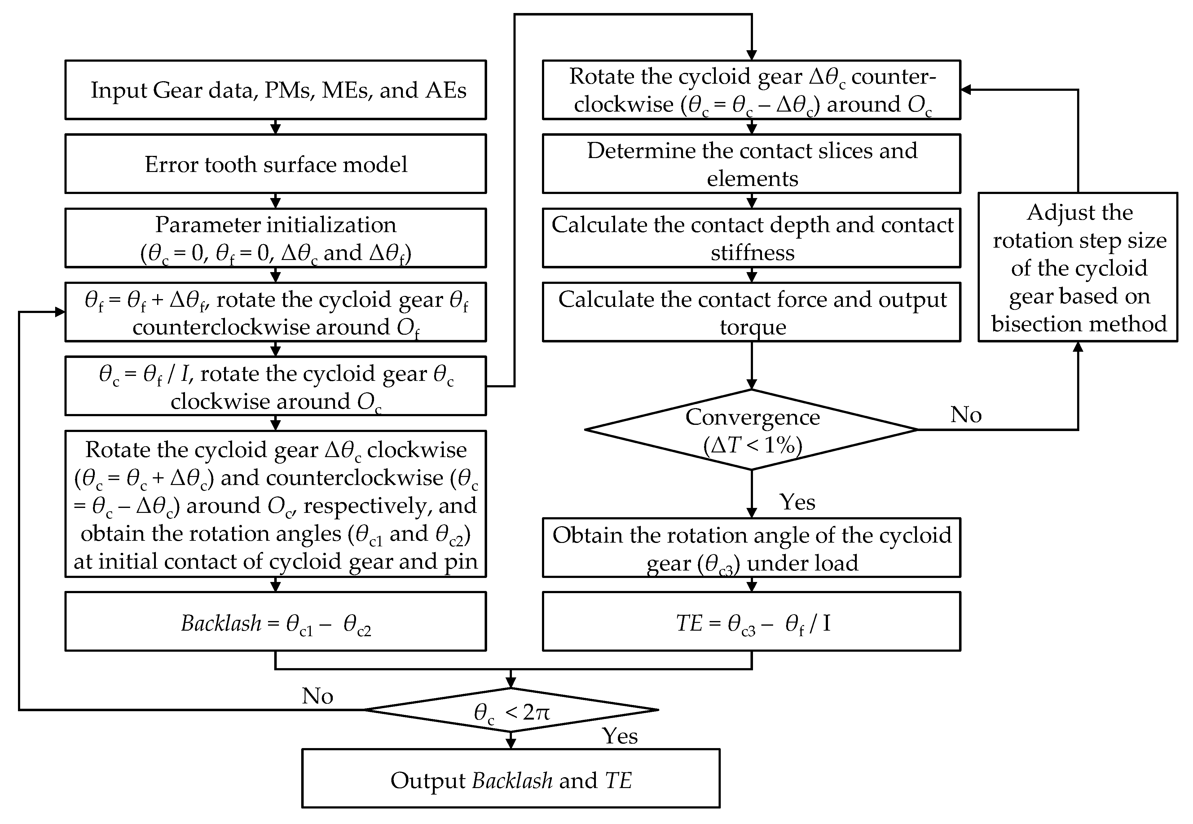
3. Calculation Principle of Transmission Error and Backlash

As shown in Figure 4, the TE and backlash of the cycloid-pin pair are calculated with an iterative process. Firstly, the error tooth surface model proposed in Section 2 is generated based on the input gear data, PMs, MEs, and AEs. Figure 5a shows the tooth contact model of the cycloid gear and pin. XfOfYf is the fixed coordinate system established at the center of the pin center circle (Of), and the center of the cycloid gear is defined as Oc. The eccentric distance between Of and Oc is e. It is well known that a cycloid gear not only rotates counterclockwise with the input crankshaft around Of, but also rotates clockwise around Oc to drive the output mechanism to rotate. The rotation angles of the cycloid gear around Of and Oc are defined as θf and θc, respectively, and the rotation step sizes of the cycloid gear around Of and Oc are defined as Δθf and Δθc, respectively. At the first position of the cycloid gear, θf and θc are initialized to zero.
To calculate the TE and backlash corresponding to each input angle of the gear pair, the cycloid gear is first rotated θf (θf = θf + Δθf) counterclockwise around Of and θc (θc = θf/I) clockwise around Oc with coordinated transformation, when the cycloid gear and the pins are in the theoretical meshing position. I is the transmission ratio of the cycloid-pin gear pair. The coordinate transformation matrices of the cycloid gear rotating around Of and Oc (Mof and Moc) are given as follows:
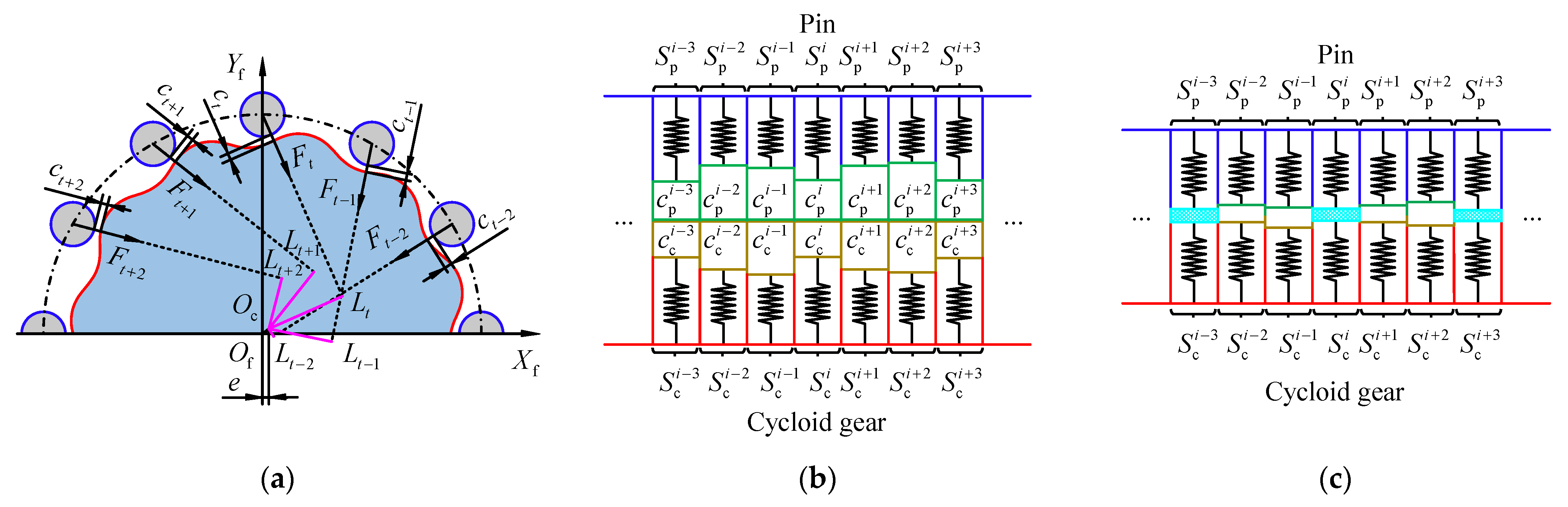
M of = [ 1 0 0 e cos θ f 0 1 0 e sin θ f 0 0 1 0 0 0 0 1 ] ,
M oc = [ cos θ c sin θ c 0 e cos θ f e cos ( θ f + θ c ) sin θ c cos θ c 0 e sin θ f e sin ( θ f + θ c ) 0 0 1 0 0 0 0 1 ] .
As shown in Figure 5a, when the cycloid gear is in the theoretical meshing position, there is a different initial clearance (⋯, ct−2, ct−1, ct, ct+1, ct+2, ⋯) between the cycloid gear and each pin due to the influences of the PMs, MEs, and AEs. In published works, the slicing method has been widely used to calculate the mesh stiffness of a helical gear pair [32,33,34,35,36]. According to the error tooth surface model proposed in Section 2, the cycloid gear and pin can also be regarded as composed of n1c and n1p slices, respectively, and each slice is composed of n2c and n2p elements (see Figure 2a). Thus, as shown in Figure 5b, the clearance ct is the minimum clearance in all slices (⋯, S p i 1 , S p i , S p i + 1 , ⋯, and, ⋯, S c i 1 , S c i , S c i + 1 , ⋯) along the tooth width direction. Since each group of slices ( S p i and S c i ) is also composed of multiple discrete elements, the clearance ( c p i + c c i ) between each group of slices is the minimum clearance of all elements on the two slices. Then the cycloid gear is rotated counterclockwise by Δθc around Oc to approach the pin. As the cycloid gear continues to rotate around Oc, the clearances c p i + c c i are continuously reduced and contact deflection even occurs (see Figure 5c). In the initial stage of contact between the cycloid gear and pin, the total output torque generated by the gear pair is not enough to balance the external load, and the iterative process is continued until the difference between the total output torque and the external load converge within 1%. To improve the calculation efficiency, the rotation step size (Δθc) is adjusted according to the bisection method.
When the total output torque of the gear pair is balanced with the external load, the rotation angle of the cycloid gear around Oc is defined as θc3. The TE is given as follows:
T E = θ f / I θ c 3 .
In contrast to the TE, the calculation of the backlash does not consider the influence of the tooth deflection under a load. When the cycloid gear is rotated to the theoretical meshing position, the cycloid gear is rotated clockwise and counterclockwise around Oc, and the rotation angles (θc1 and θc2) of the cycloid gear around Oc at the initial contact in the two directions are obtained. The backlash is given as follows:
B a c k l a s h = θ c 2 θ c 1 .
According to the above detailed description of the calculation process of the TE and backlash, the determination of the contact between the cycloid gear and pin and the calculation of the output torque generated by the cycloid-pin gear pair in the iteration process are the keys to calculating the TE and backlash. According to the principle of the slicing method, it is assumed that each slice along the tooth width is independent and that the load on one slice cannot convey deflections to the neighboring slices [37]. Additionally, due to the geometry of a cycloid-pin gear pair, the contact deflection is much larger than the tooth bending and shear deflections, and it is regarded as local deflection [13]. Thus, only the contact deflection between the tooth surfaces is considered in this study, and it is feasible to ignore the influence of the load deflection between the adjacent slices along the tooth width.
As mentioned above, each slice in Figure 5b is composed of multiple discrete elements, and each discrete element is approximately represented as a cylindrical surface. The position and the size of these cylindrical surfaces have been determined according to the description in 
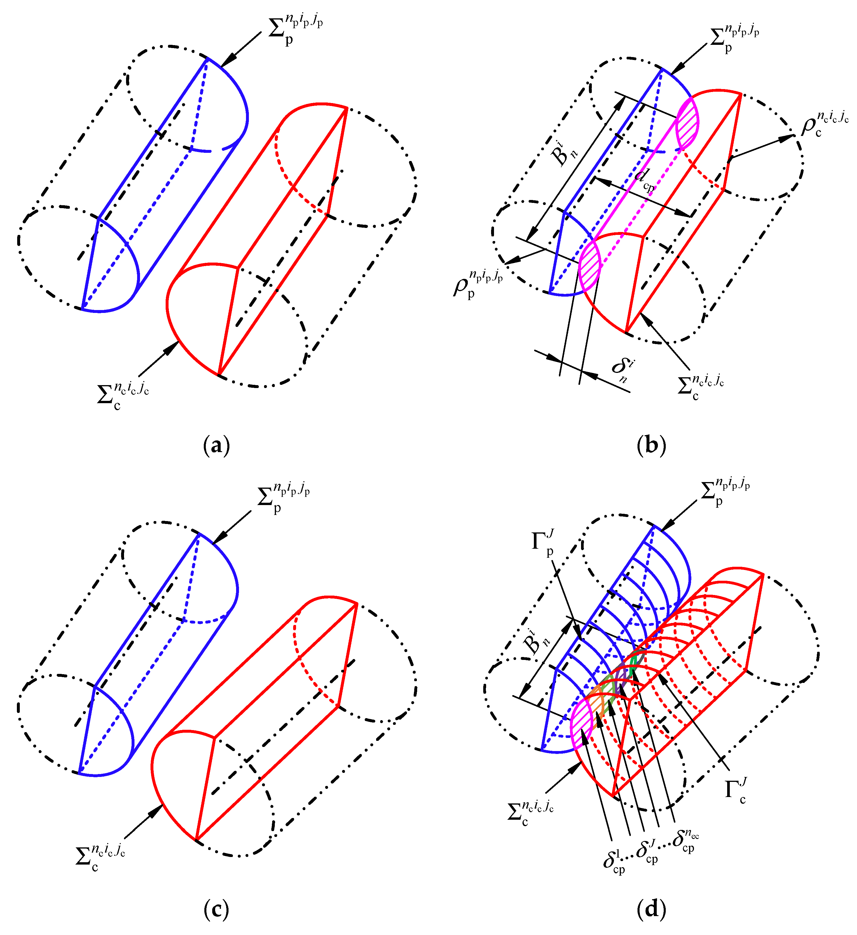
Section 2. Thus, the contact of each group of slices can be converted into the contact of the corresponding equivalent cylindrical surfaces. There are four possible contact status for any two elements on each group of slices. As shown in Figure 6a,b, when the misalignment deviations (φ and γ) are not considered, the axes of the two elements ( Σ c n c i c j c and Σ p n p i p j p ) are parallel to each other. The contact width is equal to the element width, and the contact depth is equal to the difference between the sum of the radii of curvature and the distance between the centers of curvature corresponding to the two control points. The contact width and depth are given as follows:
B n i = B p n 1 p ,
δ n i = ρ c n c i c j c + ρ p n p i p j p d cp ,
where dcp is the distance between the centers of curvature corresponding to the two control points, which can be obtained based on the coordinates, radius of curvature, and normal vector at the element control point, as well as the axis direction vector of the approximate cylinder described in Section 2. When the contact depth δ n i is greater than zero, the two elements are in contact. Otherwise, they are not involved in contact.
As shown in Figure 6c,d, when the misalignment deviations (φ and γ) are considered, the axis of cycloid gear is not parallel to the axis of the pin. To calculate the contact depth in these two cases, the two cylindrical surfaces are discretized into ne arcs. It is assumed that there are nec pairs of arcs that meet the above contact condition, and the mean of their contact depth is approximated to the contact depth of the two discrete elements. The contact width and depth are given as follows:
B n i = B p n ec n 1 p n e ,
δ n i = J = 1 n ec δ cp J / n ec ,
where δ cp J is the contact depth of the arcs Γ p J and Γ c J .
The Hertzian contact stiffness of any two elements is given as follows [13]:
K n i = F n i δ n i = π B n i 2 [ 1 υ c 2 E c ( ln 4 ρ c n c i c j c b n i 1 2 ) + 1 υ p 2 E p ( ln 4 ρ p n p i p j p b n i 1 2 ) ] ,
where Ec and Ep are the modulus of elasticity, and υc and υp are the Poisson’s ratios, where the subscripts c and p represent cycloid gear and pin, respectively. B n i is the contact width and b n i is the semi-Hertzian contact width, which can be calculated with:
b n i = 4 F n i ρ π B n i E ,
E = E c E p E p ( 1 υ c 2 ) + E c ( 1 υ p 2 ) ,
ρ = ρ c n c i c j c ρ p n p i p j p ρ c n c i c j c + ρ p n p i p j p ,
where E* and ρ* are the equivalent elasticity modulus and the equivalent radius of curvature, respectively.
The total output torque generated by the cycloid-pin gear pair is given as follows:
T out = n = 1 z pc ( i = 1 n s K n i δ n i L n i ) ,
where zpc is the number of contacted pins and L n i is the arm of force of the slice S c i (see Figure 5a), which is given as follows:
L n i = | P Q × n c n c i c j c | | n c n c i c j c | ,
where in the vector PQ, P is the control point of the contact element Σ c n c i c j c on the slice S c i . The coordinates of P can be obtained using Equation (6), and Q is the corresponding point of P on the axis of the cycloid gear. The coordinates of Q are given as follows:
[ X Q n c i c j c Y Q n c i c j c Z Q n c i c j c 1 ] T = M ae [ e cos θ f e sin θ f B c B c ( i c 1 / 2 ) / n 1 c 1 ] T .
Thus, the vector PQ is given as follows:
P Q = [ X Q n c i c j c X c n c i c j c Y Q n i c j c Y c n c i c j c Z Q n c i c j c Z c n c i c j c 1 ] T .

4. Validation of Proposed Method

To verify the effectiveness of the proposed calculation method of the TE and backlash, a cycloid-pin gear pair (see Table 1) is applied to the presented method, and the calculation results are discussed in this section. The number of discrete elements of the cycloid gear (n1c) and pin (n1p) along the tooth profile is 800, and the number of discrete elements along the tooth width (n2c and n2p) is 100. The rotation step sizes Δθf and Δθc are 0.1° and 1/60 arcsec, respectively. When the tooth surfaces of the cycloid gear and pin are perfect surfaces without errors, the calculation results are as shown in 
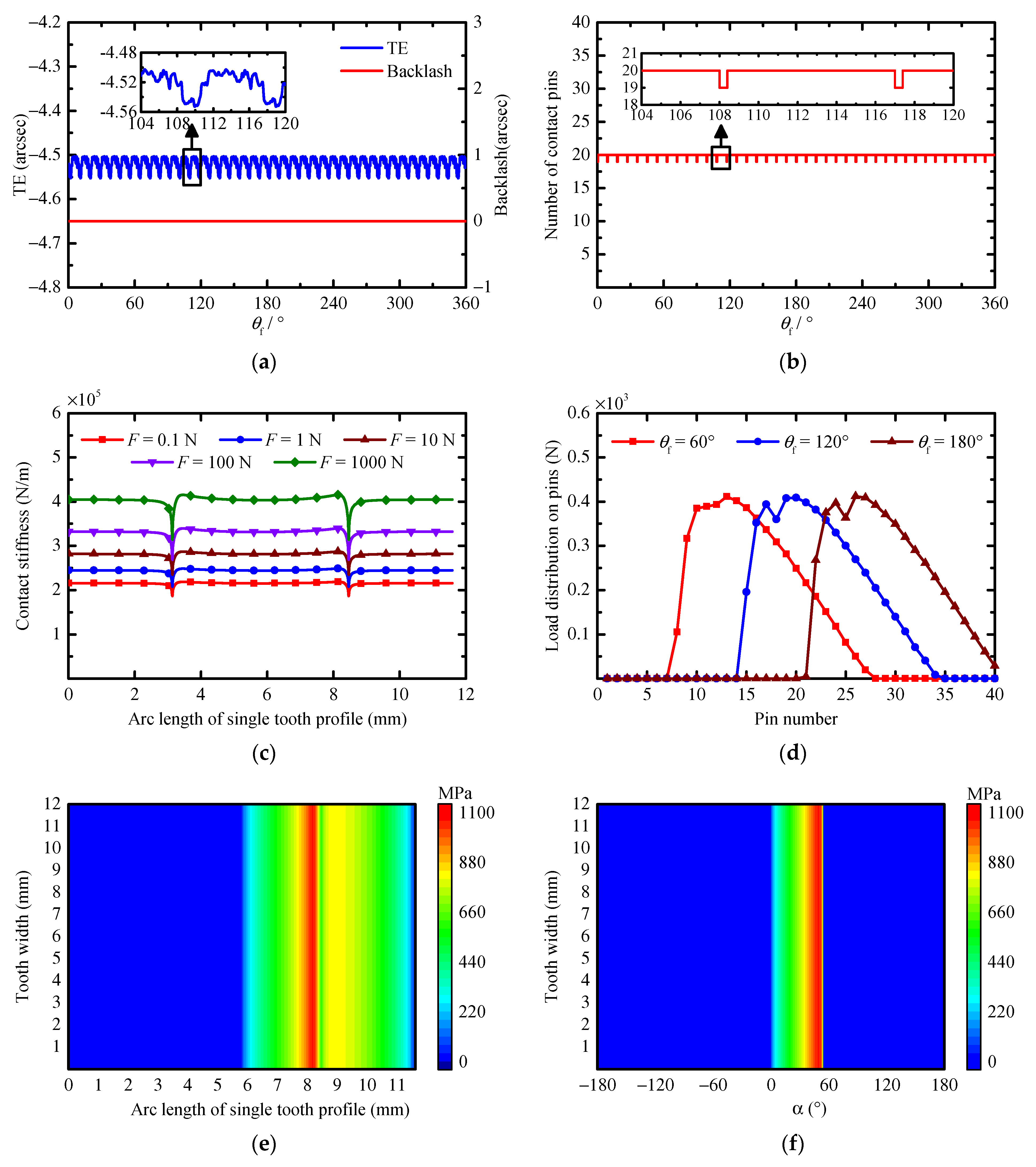
Figure 7. In the rest of paper, the terms “MTE” and “MB” refer to the mean values of the TE and backlash, respectively, the terms “PPTE” and “PPB” refer to the peak-to-peak values of the TE and backlash, respectively, and the term “MCS” refers to the maximum contact stress on the tooth surface.
As shown in Figure 7a, the backlash is always equal to zero during the entire meshing cycle, which is because the influence of the PMs, MEs, AEs, and the tooth deflection under a load are not considered when calculating the backlash. Additionally, according to Figure 7a,b, it is not difficult to find that both the TE and the number of contact pins change periodically with θf, and the maximum number and the minimum number of contact pins are 20 and 19, respectively. Theoretically, when the tooth surfaces are perfect, half of the pins are always in contact with the cycloid gear during the entire meshing cycle. However, due to the influence of the tooth deflection under a load, the tooth pair in the critical contact state loses contact.
The MTE and PPTE are −4.5206 arcsec and 0.0531 arcsec, respectively. According to Equation (16), due to the tooth deflection under a load, the actual rotation angle of the cycloid gear around Oc is greater than its theoretical value, resulting in a negative mean value. Additionally, both the contact stiffness and the load shared on each pin are different at the different positions of θf, which leads to the different tooth deflection under a load. This is the reason why the TE has small fluctuations between its peaks and troughs. During the transmission of the cycloid-pin gear pair, the position of the contact point on the cycloid tooth surface changes with the rotation of the cycloid gear. However, according to Equations (22) and (23), the contact stiffness has a nonlinear relationship with the radius of curvature of the cycloid gear and the contact force. As shown in Figure 2a, the tooth surface of the cycloid gear is discrete with the same arc length along the tooth profile, and Figure 7c shows the relationship between the contact stiffness and the contact force at different arc lengths of the single cycloid tooth profile. This shows that the contact stiffness is different at the same arc length position under different loads. This is because the semi-Hertzian contact width increases with the increase in the load, which increases the contact stiffness. Additionally, the contact stiffness is different at different arc length positions under the same load, especially in the transition region of the concave and convex tooth profiles. This is because the radius of curvature of the cycloid gear varies greatly in the transition region, because the radius of curvature at the transition point is theoretically infinite. Figure 7d shows the load distribution on the pins when θf = 60°, 120°, and 180°. The load distribution on the pins shows a trend of first increasing and then decreasing. In addition, there is a significant decrease in the load on one of the pins near the maximum load region, such as the 25th pin, when θf = 180°. This is because the corresponding contact point of this pin is located near the transition region between the convex and concave tooth surfaces of cycloid gear, and the radius of curvature at the contact point is too large, resulting in a significant reduction in the contact stiffness.
Finally, the contact stress distributions on the tooth surface of the cycloid gear and pin are obtained based on Hertzian contact theory (see Figure 7e,f). This shows that the MCS is 1067.50 MPa. During the entire meshing cycle, half of the tooth surface of the single cycloid tooth is engaged in meshing, and the contact range of the tooth surface of pin ranges from zero to 54.45°, which is very close to the maximum value of α (54.3692°) calculated with Equation (2). The error of the maximum value of α is related to the number of discrete elements of the pin along the tooth profile. The MCS of the cycloid gear is located in the transition region of the concave and convex tooth surfaces and is close to the convex tooth surface. The MCS of the pin is at the position of the maximum value of α. The above results are consistent with the theoretical analysis results and the results in the literature [13,26,27], which verifies the feasibility and effectiveness of the presented calculation method.

5. Results and Discussions

It is well known that MEs and AEs are unavoidable in practical engineering applications. To avoid the tooth interference caused by MEs and AEs and to obtain better lubrication conditions, the PMs of a cycloid gear are necessary. This section describes the influence of the PMs on the TE and backlash and the optimal modification method that is obtained to ensure the high transmission accuracy of a cycloid-pin gear pair. Then, with the same conditions of the PMs, the effects of the MEs and AEs on the TE and backlash are studied, and some abnormal meshing phenomena caused by the MEs and AEs are analyzed. The cycloid-pin gear pair is shown in Table 1.

5.1. Effect of Profile Modifications

According to Ref. [13], the radial clearance (Δc) between the tip and the root of the cycloid gear and the pin generated with PMs are Δc = ΔRrp − ΔRp. To avoid the tooth interference, the radial clearance (Δc) should be a positive value. Thus, only the positive isometric modification (+ΔRrp), negative offset modification (−ΔRp), and three types of compound modification (−ΔRrp and −ΔRp, +ΔRrp and −ΔRp, and +ΔRrp and +ΔRp) are considered in this study. To quantitatively study the influence on the TE and backlash, a series of cases is applied to the proposed calculation method, as shown in Table 2. Cases 1–4 have positive isometric modification with different modification amounts, cases 5–8 have negative offset modification with different modification amounts, and cases 9–20 have three types of compound modification. Among them, case 4, case 8, and cases 9–20 have the same radial clearance. The results for different PMs are shown in Figure 8.
According to the calculation results of cases 1–4, it is not difficult to find that as the modification amount increases with isometric modification, the absolute values of the MTE and MB increase. For the offset modification, the same conclusion can be drawn from cases 5–8. However, for the same modification amount, both of the absolute values of the MTE and MB of the isometric modification are greater than those of the offset modification. Compared with the MTE and MB, both the isometric modification and the offset modification have little influence on the PPTE and PPB. These results indicate that the transmission accuracy decreases with the increase in the modification amount for both the isometric modification and the offset modification, and the isometric modification has a greater influence on the transmission accuracy than the offset modification with the same modification amount.
For the compound modification, cases 9–20 have the same radial clearance (5 μm). According to the results of the compound modification, the compound modification of the negative isometric and negative offset (−ΔRrp and −ΔRp) makes it easier to obtain a smaller backlash, and the absolute value of the MTE is also smaller. Similarly, the compound modification has little influence on the PPTE and PPB compared to their mean values. Additionally, the radial clearances of case 4 and case 8 are also 5 μm. Comparing the results of case 4, case 8, and cases 9–12, the compound modification of the negative isometric and negative offset is more conducive to improving the transmission accuracy than the isometric modification and the offset modification. To summarize, in order to obtain higher transmission accuracy, the compound modification of the negative isometric and negative offset should be preferable.
In addition, Figure 8c,d shows the mean of the number of contact pins and the MCS. Overall, when the PMs are considered, the number of contact pins is greatly reduced compared with Figure 7b, and the MCS is greatly increased compared with Figure 7e,f. This indicates that some of the original contact pins lose contact under the influence of the PMs, and the load distributed on each contact pin increases. Specifically, the mean of the number of contact pins decreases with the increase in the modification amount for both the isometric modification and the offset modification, while the MCS increases. Thus, for the isometric modification and the offset modification, the increase in the modification amount will not only reduce the transmission accuracy but also worsen the force condition of the cycloid gear and pin, thereby reducing the contact fatigue lifetime of the tooth surface. For the compound modification of the negative isometric and negative offset, with the same radial clearance, although the transmission accuracy is improved with the increase in the absolute values of ΔRrp and ΔRp, the mean of the number of contact pins is reduced, and the MCS is increased. Thus, while using the compound modification of the negative isometric and negative offset to improve the transmission accuracy, it is also necessary to reasonably determine the modification amounts of ΔRrp and ΔRp on the basis of considering the force condition on the tooth surfaces of the cycloid gear and pin.

5.2. Effect of Manufacturing Errors

According to Section 2, the MEs considered in this study include the total profile deviation of the cycloid gear, and the total profile deviation, pitch deviation, and center circle diameter deviation of the pin. To study their effects on the transmission accuracy, a specific case is applied for the proposed calculation method. The MEs in this case are F α c = ±3 μm, Fp = 15 μm, δRp = 4 μm, and the upper and lower deviations of F α p are zero and −2 μm, respectively. The pitch deviation is usually considered to be the long-term components of the MEs [38], and the linear function [11] and the sine function [38,39,40] are generally used to simulate the cumulative pitch deviation (Fp) in published works. However, these two functions ignore the effect of the randomness of the pitch deviation on the contact state of the gear teeth. Thus, a sine function and a random variable that obeys the normal distribution are superimposed to simulate the cumulative pitch deviation in this study. The expectation and the standard deviation of the normal distribution are 0 μm and 2 μm, respectively. The cumulative pitch deviation of the pins used in this study is shown in Figure 9. Additionally, it is assumed that the profile deviation of each discrete element on the tooth surface is randomly distributed in its tolerance zone. To ensure the lubrication requirements and the compensation for MEs, the compound modification of the negative isometric and negative offset is adopted based on the results described in Section 5.1, and the PM parameters of the cycloid gear are ΔRrp = −0.004 mm and ΔRp = −0.017 mm.
Figure 10 shows the calculation results of the TE and backlash considering different types of MEs. The figure shows that the pitch deviation (Fp) not only changes the curve waveforms of the TE and backlash, but also the main source of their peak-to-peak value. The profile deviation (Fα) produces slight fluctuations in the curves of the TE and backlash compared with the results without MEs and the results considering the pin center circle diameter deviation (δRp). This is mainly because the contact element on each slice has changed under the influence of the profile deviation, which leads to changes in the contact stiffness and the tooth deflection under a load. The fluctuations of the TE and backlash also cause the PPTE and PPB to increase, but the increase is very small compared to the results considering the pitch deviation. In addition, the profile deviation and the pin center circle diameter deviation mainly affect the MTE and MB. According to the above analysis, the MTE and MB are mainly related to the initial gap between the tooth surfaces. For the profile deviation, the initial gap mainly depends on the upper deviation of Fα. Since the upper deviations of F α c and F α p have a similar effect on the initial gap, only the influence of the upper deviation of F α c on the TE and backlash is considered in this study. In the above case, the upper and lower deviations of F α c are 3 μm and −3 μm, respectively. To quantitatively study the influence of Fα on the MTE and MB, the above-mentioned F α c are moved equivalently to obtained different upper deviations, and the TE and the backlash for different F α c and δRp are calculated (see Figure 11).
According to Figure 11, the absolute values of the MTE and MB decrease with the increase in the upper deviation of F α c , and the values increase with the increase in δRp. Additionally, the MTE and MB have an approximate linear relationship with the upper deviation of F α c and the δRp, and the slopes of the TE and backlash curves are used to evaluate their influence on the MTE and MB. The slopes of the TE and backlash curves in Figure 11a are 4.1848 and −8.4004, respectively, and the slopes of the TE and backlash curves in Figure 11b are −2.6029 and 4.7578, respectively. This indicates that the profile deviation has a greater effect on the MTE and MB than the pin center circle diameter deviation.
In addition, the number of contact pins and the load distribution on the pins with different types of MEs (corresponding to Figure 10) are calculated, as shown in Figure 12. As shown in Figure 12a, when the pitch deviation is considered, the number of contact pins varies from three to ten, instead of periodically changing between six and seven pins when the MEs are not considered. This shows that the early contact (e.g., θf = 80°) or the instantaneous mesh-apart (e.g., θf = 180°) of the pins occur due to the influence of the pitch deviation. The irregular changes of the number of contact pins in a large range are the main reasons for the changes in the waveforms of the TE and backlash and the increase in their peak-to-peak value (see Figure 10), and this will also cause the vibration of the transmission system and worsen the force condition of the pins. Figure 12b shows that the load on some of the pins is significantly increased when the pitch deviation is considered (e.g., the 11th pin when θf = 60°), which will greatly increase the MCS.
Since the upper deviations of the profile deviations F α c and F α p are 3 μm and zero, respectively, the initial gap between the tooth surfaces is reduced, which leads to an increase in the mean value of the number of contact pins, as shown in Figure 12c. Additionally, due to the influence of the profile deviation, the minimum initial gap between the tooth surfaces of each pair is different, which leads to the irregular changes in the number of contact pins, and this is also another reason for the slight fluctuations in the curves of the TE and backlash in Figure 10. Compared with Figure 12a,c, the number of contact pins changes more regularly and periodically under the influence of the pin center circle diameter deviation, as shown in Figure 12e. Since the pin center circle diameter deviation is 4 μm in this case, the initial gap between the tooth surfaces increases, which leads to a decrease in the mean value of the number of contact pins. As can be observed by comparing Figure 12b,d,f, the profile deviation and the pin center circle diameter deviation have much less influence on the load distribution on the pins than the pitch deviation. To summarize, the pitch deviation is the main factor that affects the TE and backlash in the MEs. It is suggested that the pitch deviation should be strictly controlled in the gear manufacturing process to achieve a smaller PPTE and PPB, and a smaller MTE and MB can be obtained through different tolerance allocation of the profile deviation and the pin center circle diameter deviation during the installation of the gear pair.

5.3. Effect of Assembly Errors

AEs are also another major factor affecting the TE and backlash. According to the definition of the AEs in Section 2, the AEs are divided into the center distance deviations (Δx and Δy) and the misalignment deviations (φ and γ). Since Δx and Δy have similar effects on the TE and backlash, only the influences of Δy, φ, and γ are investigated in this section. To ensure the lubrication requirements and the compensation for the AEs, the compound modification of the negative isometric and negative offset is applied, and the PM parameters of the cycloid gear are also determined to be ΔRrp = −0.004 mm and ΔRp = −0.0017 mm. The calculation results for the TE and backlash considering different center distance deviations are shown in Figure 13.
According to Figure 13a,b, the waveforms of the curves of the TE and backlash change significantly under the influence of the center distance deviation, which is similar to the harmonic function curve. According to Figure 13c,d, as the absolute value of Δy increases, the PPTE, PPB, and MTE increase, while the MB decreases, and the influence of the center distance deviation on the MB is greater than that on the MTE. Figure 14 shows the number of contact pins when Δy = 9 and −9 μm, as well as the load distribution on the pins when Δy = 9 μm. According to Figure 14a, when Δy = 9 μm, the number of contact pins first decreases and then increases with the change of θf, which is caused by the change of the initial gap between the tooth surfaces. In addition, the load on the pins increases significantly with the decrease in the number of contact pins (e.g., when θf = 90° in Figure 14b), which will increase the MCS and shorten the contact fatigue lifetime of the tooth surface. At the same time, this will also produce vibration and noise in the gear system.
The calculation results of the TE and backlash considering the misalignment deviations φ and γ are shown in Figure 15. Similar to the center distance deviation, both the misalignment deviations φ and γ have a greater effect on the waveform of the curves of the TE and backlash. The curves of the TE and backlash considering the misalignment deviations φ and γ are also similar to the harmonic function curve. When φ and γ have the same value, the PPTE and PPB considering the misalignment deviation φ are equal to the PPTE and PPB considering the misalignment deviation γ, while their phase difference is 90°. With the increase in φ and γ, both the PPTE and PPB increase and the MB decreases, while the misalignment deviations φ and γ have little effect on the MTE. Although the misalignment deviations φ and γ are conducive to reducing the MB, the adverse effect of the increase in the PPTE and PPB on the transmission accuracy cannot be ignored.
Figure 16 shows the number of contact pins and the load distribution on pins when the misalignment deviations φ and γ are equal to 0.02°. According to Figure 16a,c, the misalignment deviations φ and γ will cause the mean number of contact pins to increase, and the number of new contact pins is different with the rotation angle of the cycloid gear. Theoretically, the load distributed on each pin should decrease when the number of contact pins increases, but in fact, the load on some contact pins increases instead, such as the 27th and 28th pins shown in Figure 16b when θf = 180°. In addition, even if the number of contact pins remains the same, the load distributed to each contact pin is different from that without the misalignment deviations, such as the 13th to 18th pins, shown in Figure 16d, when θf = 90°. To analyze the cause for the change of the load distribution on the contact pins, the instantaneous contact lines on the tooth surface of the contact pins are calculated for different θf, φ, and γ, as shown in Figure 17.
According to Figure 17a–c, the number of contact pins at the three different positions of the cycloid gear (θf = 90°, θf = 180° and θf = 270°) is the same when the misalignment deviations are not considered, and the force condition on the tooth surface of the contact pins at the three different position is similar. As shown in Figure 17d–f, when φ = 0.02°, there are two new pins involved in contact at the three positions, and a serious eccentric load occurs on the tooth surface of some pins, such as the 14th to 16th pins when θf = 90° (see Figure 17d). The contact line on the tooth surface of some pins is shortened, such as the 17th to 20th pins when θf = 90°, which indicates that part of the tooth surface of these pins loses contact. A similar eccentric load phenomenon also occurs when γ = 0.02°, as shown in Figure 17g–i. These phenomena explain why the number of contact pins is the same but the load distribution on each contact pin is different when the misalignment deviations are considered, and why the load on some pins increases instead of decreases when the number of contact pins increases. In addition, when the values of φ and γ are equal, the force condition on the surface of the contact pins shown in Figure 17d is similar to that shown in Figure 17h, and the force condition on the surface of contact pins shown in Figure 17e is also similar to that shown in Figure 17i. The difference between the θf in Figure 17d,h is 90°, and the difference between the θf in Figure 17e,i is also 90°. This is the same as the above conclusion for the 90° phase difference of the TE curves (or the backlash curves) when φ and γ are considered (see Figure 15).
To summarize, both the center distance deviation (Δy) and the misalignment deviations (φ and γ) will change the waveform of the curves of the TE and backlash, and the PPTE and PPB will increase with the increase in these deviations. The two misalignment deviations φ and γ have a similar influence on the TE and backlash, and there is a phase difference in the curves of the TE and backlash for the two misalignment deviations. When the center distance deviation is considered, the number of contact pins will increase or decrease with the rotation of the cycloid gear, while the number of contact pins will increase under the influence of the misalignment deviations. Although the increase in the number of contact pins helps to improve the force condition of each contact pin in theory, the misalignment deviations will cause serious eccentric load on the tooth surface of the contact pins. This will increase the MCS and shorten the contact fatigue lifetime of the tooth surface, and the uneven load distribution on the tooth surface will cause the transmission accuracy to decrease and at the same time accelerate the tooth surface wear and reduce the transmission accuracy lifetime of the cycloid-pin gear pair.

6. Conclusions

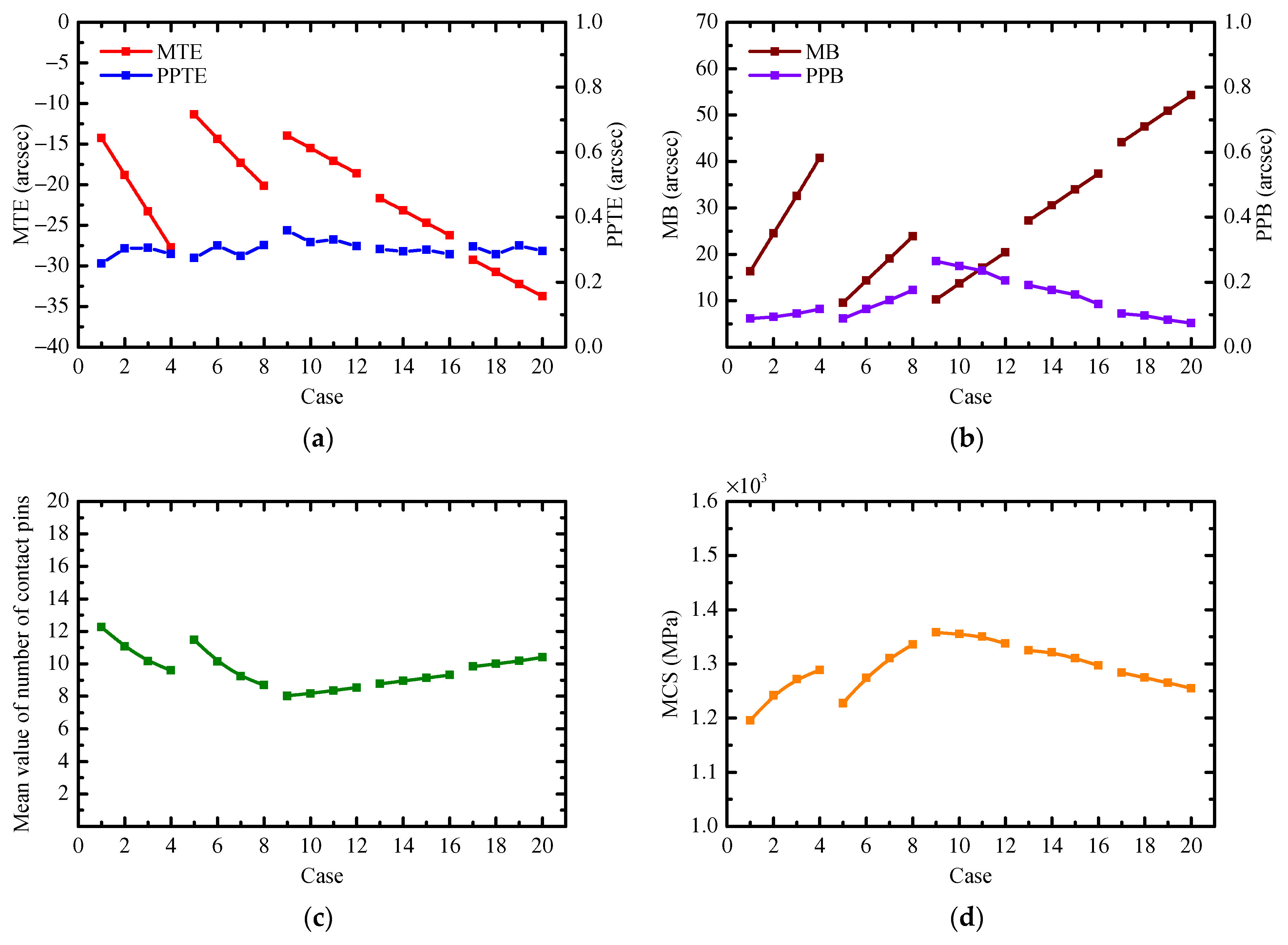
In this study, a novel approach for calculating the transmission accuracy of a cycloid-pin gear pair based on a three-dimensional error tooth surface model has been proposed. Compared with the traditional analysis method for a cycloid-pin gear pair, this method has the capability to consider the influence of some abnormal meshing phenomena caused by PMs, MEs, and AEs on the tooth contact state, TE, and backlash, such as the instantaneous mesh-apart of tooth pairs and the eccentric load on a tooth surface. The feasibility and effectiveness of this method is validated by comparison with the theoretical analysis results and the results in the literature.
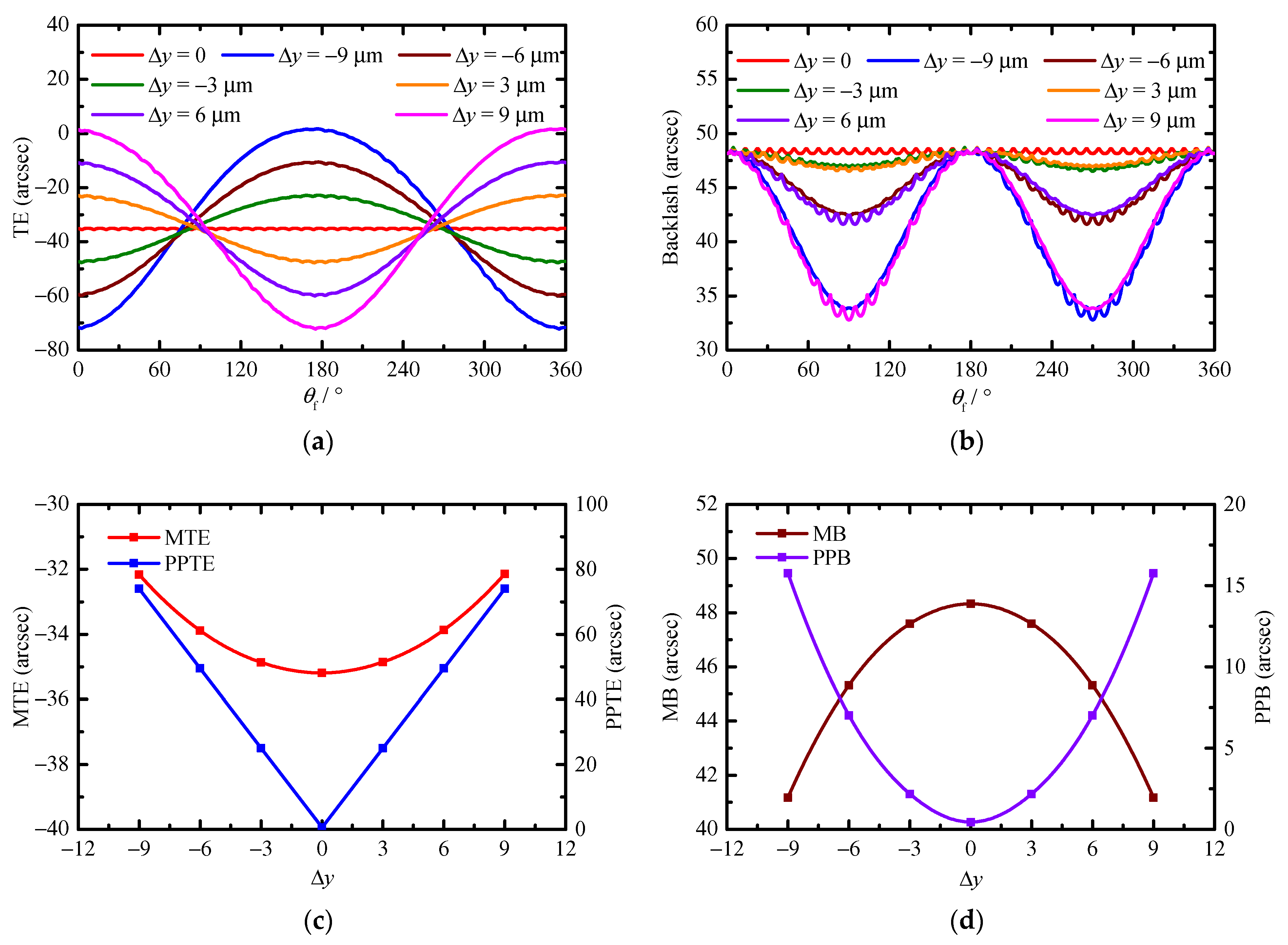
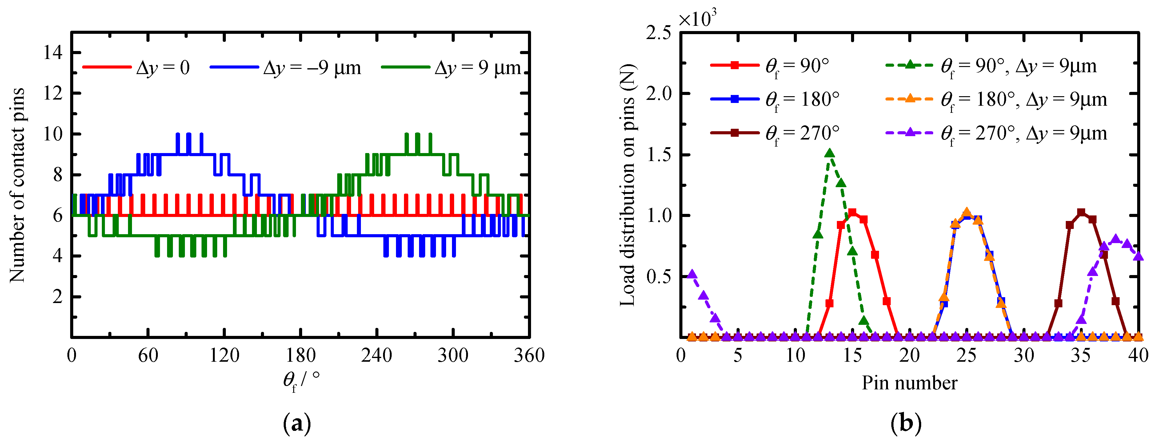
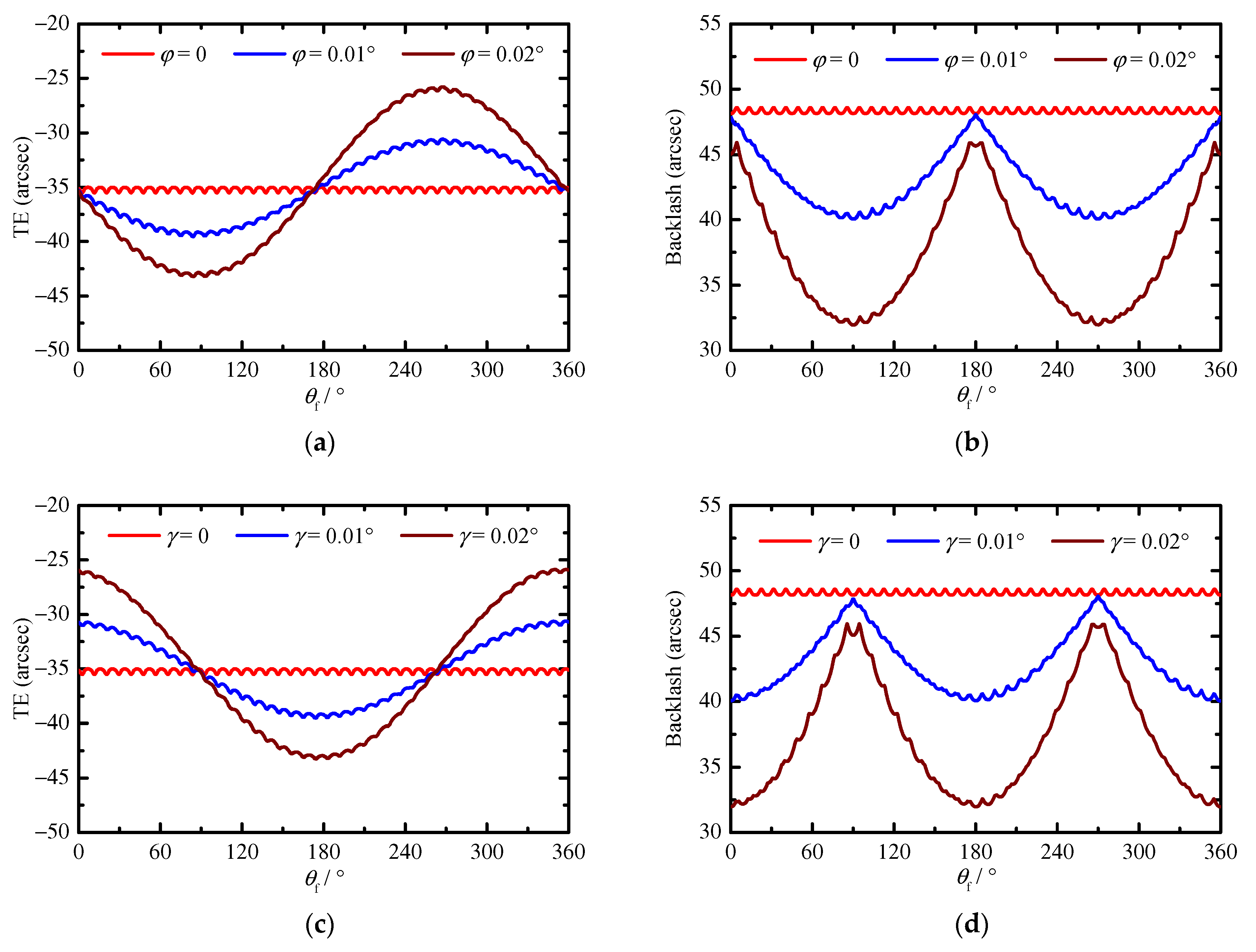
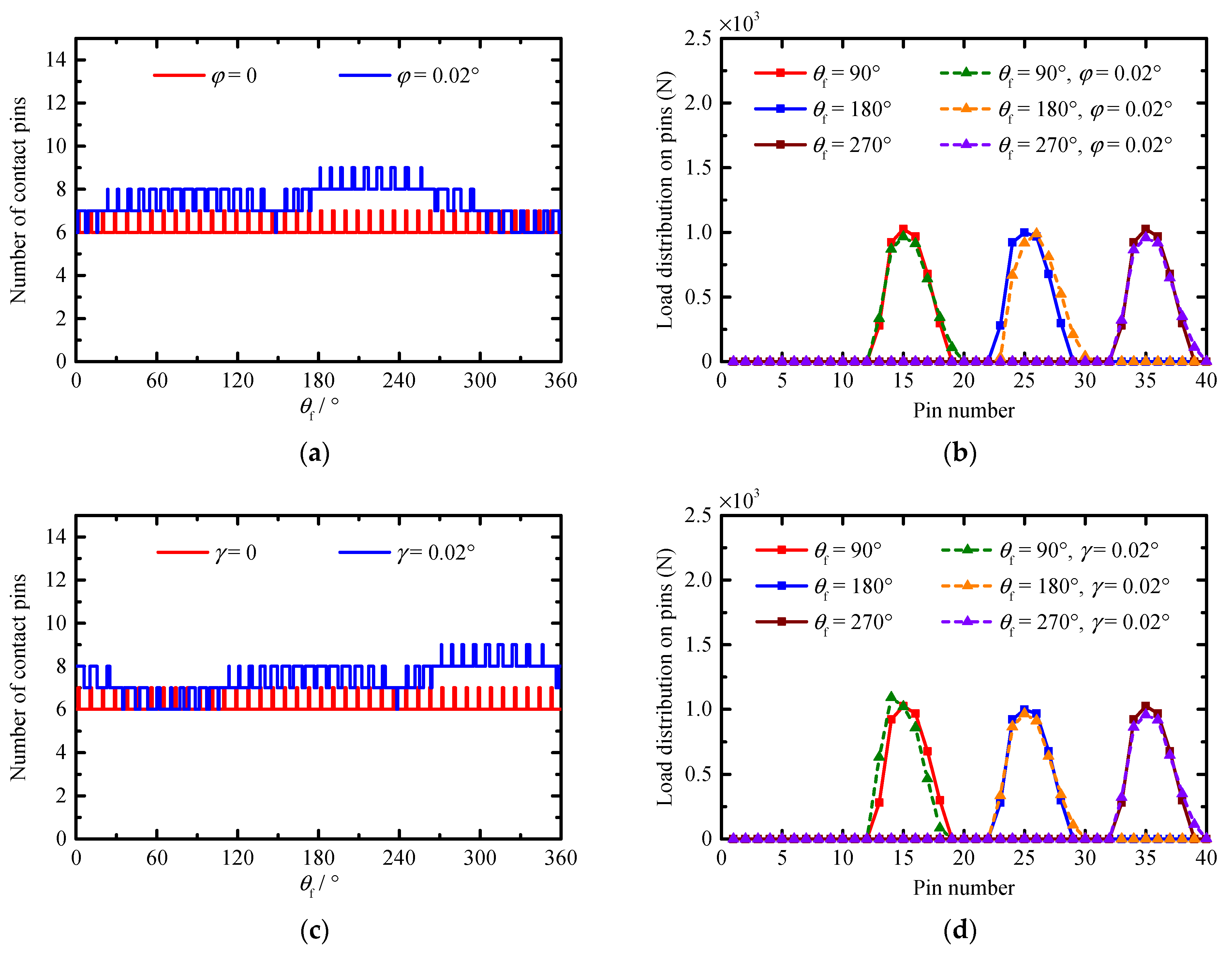
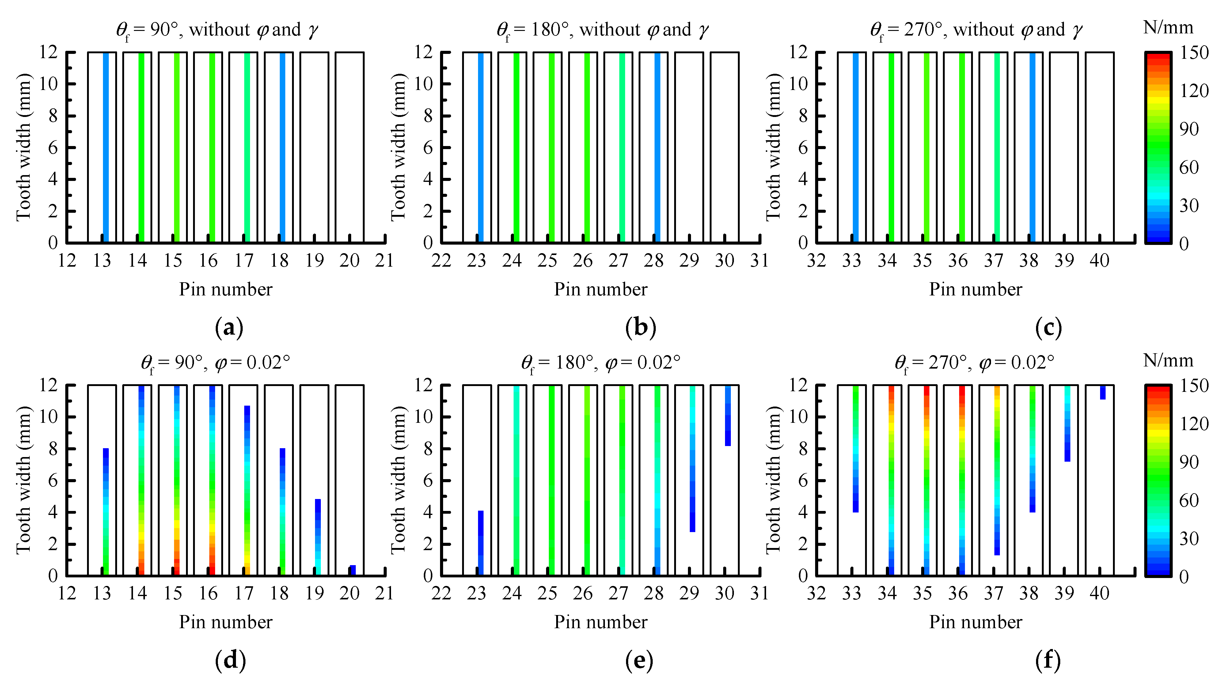
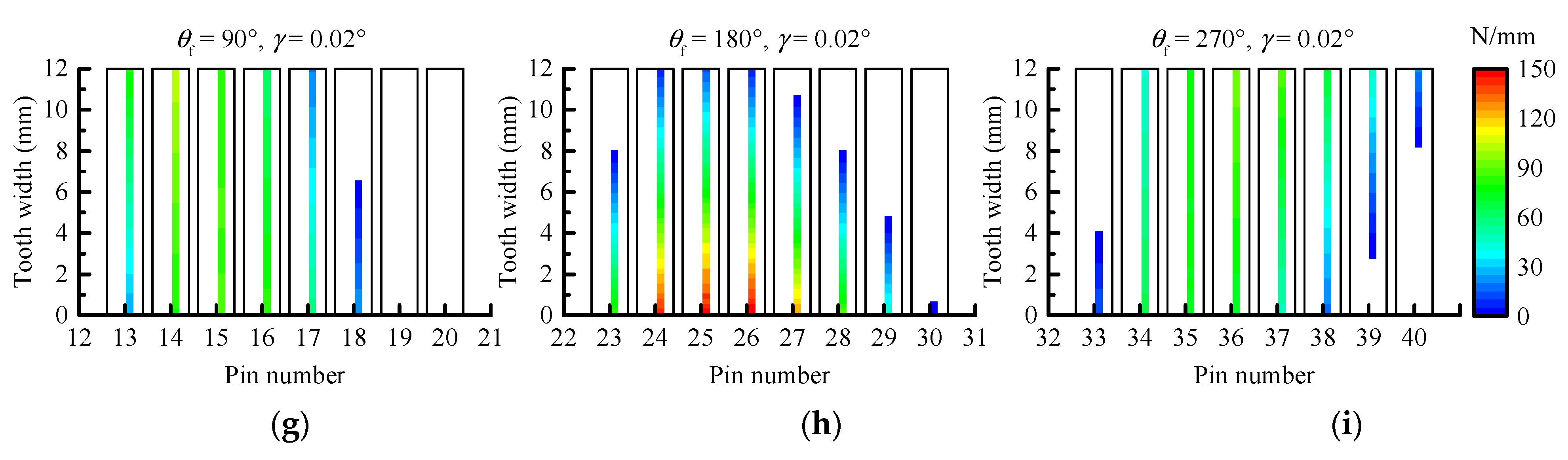
Based on this method, a series of cases is simulated to quantitatively study the influence of PMs, MEs, and AEs on the TE, backlash, the number of contact pins, load distribution on pins, contact stress, and instantaneous contact lines on the tooth surface of a pin. The obtained results show that the compound modification of the negative isometric and negative offset should be preferred in order to avoid the tooth interference and to obtain higher transmission accuracy. With this compound modification method, although the increase in the modification amount improves the transmission accuracy; this increase also leads to a decrease in the mean of the number of contact pins and an increase in the MCS. Among the MEs and AEs, the pitch deviation, the center distance deviation, and the misalignment deviations are the main influencing factors of the TE and backlash. They not only change the waveform of the TE and backlash curves, but also the main source of the peak-to-peak values of the TE and backlash, while the profile deviation and the pin center circle diameter deviation mainly affect the mean values of the TE and backlash. In addition, the pitch deviation and the center distance deviation will cause the number of contact pins to fluctuate in a large range, and they will cause the load on some pins to increase significantly. Under the influence of the misalignment deviations, although the mean of the number of contact pins increases and the load distribution on the pins does not change significantly, a serious eccentric load occurs on the tooth surface of some contact pins. The increase in the load on the pins and the occurrence of the eccentric load not only increase the MCS and shorten the contact fatigue lifetime of the tooth surface, but they also accelerate the tooth surface wear and reduce the transmission accuracy lifetime of the cycloid-pin gear pair.
The proposed method and the above conclusions are of great significance for the optimal design of the tooth profile of a cycloid gear, the tolerance allocation during the installation of a gear pair, and the accurate prediction of the TE and backlash of a cycloid-pin gear pair. The error tooth surface in this study is obtained through different probability distribution functions based on the tolerance range of various errors, and this method is expected to be used for the prediction of the transmission accuracy range of the gear pair in engineering practice. The error tooth surface can also be generated using the measurement coordinates of the element control point on the tooth surface, and this method can provide more accurate internal excitation data for the dynamic analysis of a cycloid-pin gear pair, which will be implemented in future research.

Author Contributions

Conceptualization, C.L. and W.S.; methodology C.L. and W.S.; validation, L.X.; data curation, K.L.; writing—original draft preparation, C.L.; writing—review and editing, W.S. and L.X.; funding acquisition W.S.; All authors have read and agreed to the published version of the manuscript.

Funding

This research was funded by the National Natural Science Foundation of China, grant number 51675061.

Institutional Review Board Statement

Not applicable.

Conflicts of Interest

The authors declare no conflict of interest.

References

  1. Botsiber, D.W.; Kingston, L. Cycloid speed reducer. Mach. Des. 1956, 28, 65–69. [Google Scholar]
  2. Pollitt, E.P. Some applications of the cycloid in machine design. ASME J. Eng. Ind. 1960, 82, 407–414. [Google Scholar] [CrossRef]
  3. Li, X.; He, W.; Li, L.; Schmidt, L.C. A new cycloid drive with high-load capacity and high efficiency. ASME J. Mech. Des. 2004, 126, 683–686. [Google Scholar] [CrossRef]
  4. Liu, J.; Matsumura, S.; Chen, B.; Houjoh, H. Torsional stiffness calculation of double-enveloping cycloid drive. J. Adv. Mech. Des. Syst. 2012, 6, 2–14. [Google Scholar] [CrossRef] [Green Version]
  5. Sun, X.; Han, L.; Ma, K.; Li, L.; Wang, J. Lost motion analysis of CBR reducer. Mech. Mach. Theory 2018, 120, 89–106. [Google Scholar] [CrossRef]
  6. Blagojevic, M.; Marjanovic, N.; Djordjevic, Z.; Stojanovic, B.; Disic, A. A new design of a two-stage cycloidal speed reducer. ASME J. Mech. Des. 2011, 33, 085001. [Google Scholar] [CrossRef]
  7. Lin, W.S.; Shih, Y.P.; Lee, J.J. Design of a two-stage cycloidal gear reducer with tooth modifications. Mech. Mach. Theory 2014, 79, 184–197. [Google Scholar] [CrossRef]
  8. Hsieh, C.F. The effect on dynamics of using a new transmission design for eccentric speed reducers. Mech. Mach. Theory 2014, 80, 1–16. [Google Scholar] [CrossRef]
  9. Blanche, J.G.; Yang, D.C.H. Cycloid drives with machining tolerances. J. Mech. Transm. Autom. Des. 1989, 111, 337–344. [Google Scholar] [CrossRef]
  10. Yang, D.C.H.; Blanche, J.G. Design and application guidelines for cycloid. Mech. Mach. Theory 1990, 25, 487–501. [Google Scholar] [CrossRef]
  11. Lin, K.S.; Chan, K.Y.; Lee, J.J. Kinematic error analysis and tolerance allocation of cycloidal gear reducers. Mech. Mach. Theory 2018, 124, 73–91. [Google Scholar] [CrossRef]
  12. Li, T.; Tian, M.; Xu, H.; Deng, X.; An, X.; Su, J. Meshing contact analysis of cycloidal-pin gear in RV reducer considering the influence of manufacturing error. J. Braz. Soc. Mech. Sci. Eng. 2020, 42, 133. [Google Scholar] [CrossRef]
  13. Li, X.; Li, C.; Wang, Y.; Chen, B.; Lim, T.C. Analysis of a cycloid speed reducer considering tooth profile modification and clearance-fit output mechanism. ASME J. Mech. Des. 2017, 139, 033303. [Google Scholar] [CrossRef]
  14. Han, L.; Guo, F. Global sensitivity analysis of transmission accuracy for RV-type cycloid-pin drive. J. Mech. Sci. Tech. 2016, 30, 1225–1231. [Google Scholar] [CrossRef]
  15. Ivanović, L.; Devedžić, G.; Ćuković, S.; Mirić, N. Modeling of the meshing of trochoidal profiles with clearances. ASME J. Mech. Des. 2012, 134, 041003. [Google Scholar] [CrossRef]
  16. Hidaka, T.; Wang, H.Y.; Ishida, T.; Matsumoto, K.; Hashimoto, M. Rotational transmission error of K-H-V-type planetary gears with cycloid gear: 1st report, analytical method of the rotational transmission error. Trans. Jpn. Soc. Mech. Eng. Ser. C 1994, 60, 645–653. [Google Scholar] [CrossRef] [Green Version]
  17. Ishida, T.; Wang, H.Y.; Hidaka, T.; Matsumoto, K.; Hashimoto, M. Rotational transmission error of K-H-V-type planetary gears with cycloid gears: 2nd report, effects of manufacturing and assembly errors on rotational transmission error. Trans. Jpn. Soc. Mech. Eng. Ser. C 1994, 60, 3510–3517. [Google Scholar] [CrossRef] [Green Version]
  18. Meng, Y.; Wu, C.; Ling, L. Mathematical modeling of the transmission performance of 2K-H pin cycloid planetary mechanism. Mech. Mach. Theory 2007, 42, 776–790. [Google Scholar] [CrossRef]
  19. Li, T.; An, X.; Deng, X.; Li, J.; Li, Y. A new tooth profile modification method of cycloidal gears in precision reducers for robots. Appl. Sci. 2020, 10, 1266. [Google Scholar] [CrossRef] [Green Version]
  20. Kumar, N.; Kosse, V.; Oloyede, A. A new method to estimate effective elastic torsional compliance of single-stage cycloidal drives. Mech. Mach. Theory 2016, 105, 185–198. [Google Scholar] [CrossRef]
  21. Li, X.; Chen, B.; Wang, Y.; Lim, T.C. Mesh stiffness calculation of cycloid-pin gear pair with tooth profile modification and eccentricity error. J. Cent. South Univ. 2018, 25, 1717–1731. [Google Scholar] [CrossRef]
  22. Liu, Z.; Zhang, T.; Wang, Y.; Yang, C.; Zhao, Y. Experimental studies on torsional stiffness of cycloid gear based on machining parameters of tooth surfaces. Int. J. Precis. Eng. Manuf. 2019, 20, 1017–1025. [Google Scholar] [CrossRef]
  23. Gorla, C.; Davoli, P.; Rosa, F.; Longoni, C.; Chiozzi, F.; Samarani, A. Theoretical and experimental analysis of a cycloidal speed reducer. ASME J. Mech. Des. 2008, 130, 112604. [Google Scholar] [CrossRef]
  24. Mackic, T.; Blagojevic, M.; Babic, Z.; Kostic, N. Influence of design parameters on cyclo drive efficiency. J. Balkan Tribol. Assoc. 2013, 19, 497–507. [Google Scholar]
  25. Sensinger, J.W. Efficiency of high-sensitivity gear trains, such as cycloid drives. ASME J. Mech. Des. 2013, 135, 071006. [Google Scholar] [CrossRef]
  26. Malhotra, S.K.; Parameswaran, M.A. Analysis of a cycloid speed reducer. Mech. Mach. Theory 1983, 18, 491–499. [Google Scholar] [CrossRef]
  27. Xu, L.; Yang, Y. Dynamic modeling and contact analysis of a cycloid-pin gear mechanism with a turning arm cylindrical roller bearing. Mech. Mach. Theory 2016, 104, 327–349. [Google Scholar] [CrossRef]
  28. Wang, J.; Luo, S.; Su, D. Multi-objective optimal design of cycloid speed reducer based on genetic algorithm. Mech. Mach. Theory 2016, 102, 135–148. [Google Scholar] [CrossRef]
  29. Wang, Y.; Qian, Q.; Chen, G.; Jin, S.; Chen, Y. Multi-objective optimization design of cycloid pin gear planetary reducer. Adv. Mech. Eng. 2017, 9, 1–10. [Google Scholar] [CrossRef]
  30. Li, S. Design and strength analysis methods of the trochoidal gear reducer. Mech. Mach. Theory 2014, 81, 140–154. [Google Scholar] [CrossRef]
  31. Tran, T.L.; Pham, A.D.; Ahn, H.J. Lost motion analysis of one stage cycloid reducer considering tolerances. Int. J. Precis. Eng. Manuf. 2016, 17, 1009–1016. [Google Scholar] [CrossRef]
  32. Yu, W.; Mechefske, C.K. A new model for the single mesh stiffness calculation of helical gears using the slicing principle. Iran. J. Sci. Technol. Trans. Mech. Eng. 2019, 43, 503–515. [Google Scholar] [CrossRef]
  33. Huangfu, Y.; Chen, K.; Ma, H.; Che, L.; Li, Z.; Wen, B. Deformation and meshing stiffness analysis of cracked helical gear pairs. Eng. Fail. Anal. 2019, 95, 30–46. [Google Scholar] [CrossRef]
  34. Jiang, H.; Liu, F. Mesh stiffness modelling and dynamic simulation of helical gears with tooth crack propagation. Meccanica 2020, 55, 1215–1236. [Google Scholar] [CrossRef]
  35. Han, L.; Xu, L.; Qi, H. Influences of friction and mesh misalignment on time-varying mesh stiffness of helical gears. J. Mech. Sci. Technol. 2017, 31, 3121–3130. [Google Scholar] [CrossRef]
  36. Feng, M.; Ma, H.; Li, Z.; Wang, Q.; Wen, B. An improved analytical method for calculating time-varying mesh stiffness of helical gears. Meccanica 2018, 53, 1131–1145. [Google Scholar] [CrossRef]
  37. Wang, Q.; Zhang, Y. A model for analyzing stiffness and stress in a helical gear pair with tooth profile errors. J. Vib. Control 2015, 23, 272–289. [Google Scholar] [CrossRef]
  38. Yuan, B.; Chang, S.; Liu, G.; Wu, L. Quasi-static and dynamic behaviors of helical gear system with manufacturing errors. Chin. J. Mech. Eng. 2018, 31, 30. [Google Scholar] [CrossRef] [Green Version]
  39. Fernández-del-Rincón, A.; Iglesias, M.; de-Juan, A.; Diez-Ibarbia, A.; García, P.; Viadero, F. Gear transmission dynamics: Effects of index and run out errors. Appl. Acoust. 2016, 108, 63–83. [Google Scholar] [CrossRef] [Green Version]
  40. Hu, Z.; Tang, J.; Zhong, J.; Chen, S.; Yan, H. Effects of tooth profile modification on dynamic responses of a high gear-totor-bearing system. Mech. Syst. Signal. Process. 2016, 76-77, 294–318. [Google Scholar] [CrossRef]
Figure 1. Typical structure of cycloid-pin gear reducer.
Applsci 11 08671 g001
Figure 2. Tooth surface model: (a) discrete tooth surfaces and (b) coordinate systems for generating the tooth surfaces with PMs and MEs.
Applsci 11 08671 g002
Figure 3. (a) Part of the tooth surface of cycloid gear considering PMs and MEs. (b) Definition of AEs.
Applsci 11 08671 g003
Figure 4. Flow chart of the calculation process of TE and backlash.
Applsci 11 08671 g004
Figure 5. Tooth contact analysis: (a) tooth contact model of cycloid gear and pin, (b) initial position of each slice along tooth width, and (c) balance position of each slice along tooth width.
Applsci 11 08671 g005
Figure 6. Four contact status for any two elements on each group of slices: (a) elements separation without φ and γ, (b) elements contact without φ and γ, (c) elements separation considering φ and γ, (d) elements contact considering φ and γ.
Applsci 11 08671 g006
Figure 7. The results for the perfect tooth surface: (a) TE and backlash, (b) number of contact pins, (c) relationship between contact stiffness and contact force at different arc length positions, (d) load distribution on pins, (e) contact stress on the tooth surface of the cycloid gear, and (f) contact stress on the tooth surface of the pin.
Applsci 11 08671 g007
Figure 8. Results with PMs: (a) MTE and PPTE, (b) MB and PPB, (c) mean value of number of contact pins, and (d) MCS.
Applsci 11 08671 g008
Figure 9. Cumulative pitch deviation.
Applsci 11 08671 g009
Figure 10. Results with MEs: (a) TE and (b) backlash.
Applsci 11 08671 g010
Figure 11. MTE and MB with different (a) profile deviations and (b) pin center circle diameter deviations.
Applsci 11 08671 g011
Figure 12. Number of contact pins and load distribution on pins with different types of MEs: (a,b) pitch deviation, (c,d) profile deviation, (e,f) pin center circle diameter deviation.
Applsci 11 08671 g012aApplsci 11 08671 g012b
Figure 13. Results with center distance deviation: (a) TE, (b) backlash, (c) MTE and PPTE, and (d) MB and PPB.
Applsci 11 08671 g013
Figure 14. Effect of center distance deviation on (a) number of contact pins, and (b) load distribution on pins.
Applsci 11 08671 g014
Figure 15. Results with misalignment deviations: (a) TE (φ), (b) backlash (φ), (c) TE (γ), and (d) backlash (γ).
Applsci 11 08671 g015
Figure 16. Effect of misalignment deviations on (a) number of contact pins (φ = 0.02°), (b) load distribution on pins (φ = 0.02°), (c) number of contact pins (γ = 0.02°), and (d) load distribution on pins (γ = 0.02°).
Applsci 11 08671 g016
Figure 17. Contact lines on the tooth surface of the contact pins: (ac) without φ and γ, (df) φ = 0.02°, and (gi) γ = 0.02°.
Applsci 11 08671 g017aApplsci 11 08671 g017b
Table 1. Parameters of the cycloid-pin gear pair.
ParametersData
Number of cycloid gear teeth39
Number of pins40
Radius of pin (mm)3
Radius of pin center circle (mm)64
Face width of cycloid gear (mm)12
Eccentricity (mm)1.3
Output torque (Nm)206
Poisson’s ratio0.3
Elasticity modulus (GPa)206
Table 2. Cases of different PMs.
CaseRrp−ΔRp−ΔRrp and −ΔRpRrp and −ΔRpRrp and +ΔRp
1234567891011121314151617181920
ΔRrp (μm)23450000−4−3−2−112346789
ΔRp (μm)0000−2−3−4−5−9−8−7−6−4−3−2−11234
Publisher’s Note: MDPI stays neutral with regard to jurisdictional claims in published maps and institutional affiliations.

