Article

Autonomous Landing of Micro Unmanned Aerial Vehicles with Landing-Assistive Platform and Robust Spherical Object Detection

Department of Mechanical Engineering, Chung-Ang University, Seoul 06974, Korea
*
Author to whom correspondence should be addressed.
Appl. Sci. 2021, 11(18), 8555; https://doi.org/10.3390/app11188555
Submission received: 5 August 2021 / Revised: 27 August 2021 / Accepted: 10 September 2021 / Published: 15 September 2021
(This article belongs to the Section Transportation and Future Mobility)

Abstract

:
Autonomous unmanned aerial vehicle (UAV) landing can be useful in multiple applications. Precise landing is a difficult task because of the significant navigation errors of the global positioning system (GPS). To overcome these errors and to realize precise landing control, various sensors have been installed on UAVs. However, this approach can be challenging for micro UAVs (MAVs) because strong thrust forces are required to carry multiple sensors. In this study, a new autonomous MAV landing system is proposed, in which a landing platform actively assists vehicle landing. In addition to the vision system of the UAV, a camera was installed on the platform to precisely control the MAV near the landing area. The platform was also designed with various types of equipment to assist the MAV in searching, approaching, alignment, and landing. Furthermore, a novel algorithm was developed for robust spherical object detection under different illumination conditions. To validate the proposed landing system and detection algorithm, 80 flight experiments were conducted using a DJI TELLO drone, which successfully landed on the platform in every trial with a small landing position average error of 2.7 cm.

1. Introduction

The flight capabilities and applications of unmanned aerial vehicles (UAVs), along with battery technologies, have greatly expanded over the past decade. Accordingly, various UAV applications have been developed, such as surveillance [1,2], package delivery [3], hazardous rescue missions [4,5], and even personal transportation [6]. Micro UAVs (MAVs) are widely used for these applications because of their small size, stable control, and swiftness. These advantages enable MAVs to perform autonomous tasks in situations where ground vehicles cannot operate [7,8].
One of the main challenges in realizing a fully autonomous UAV is autonomous landing [9]. During landing, UAVs are vulnerable to disturbances, and small errors can lead to catastrophic results. The global positioning system (GPS) is commonly used for the positioning and navigation of UAVs [10,11]. Although GPS can guide UAVs to the area around the landing site, it cannot be used as an indicator for landing because its accuracy is not sufficiently high for precise landing. Moreover, GPS cannot be used in closed environments, such as tunnels and indoor and underground spaces. Consequently, many studies have implemented additional sensors for UAV landing control, including red, green and blue (RGB) vision systems [12,13,14], internal navigation systems [15], ultra-wideband beacons [16], ground-based infrared cameras [17,18], and radar stations [19,20]. Among positioning sensors, RGB cameras have been widely adopted in previous studies. Specifically, images obtained by a camera facing the ground have been used for landing control [12,13,14]. Pebrianti et al. [21] proposed a ground-based stereovision system for UAV hovering and landing. Simultaneous localization and mapping [22,23,24], which map the landscape for navigation and landing in unknown landscapes, have also been developed.
Multi-visual sensor systems improve the robustness and accuracy of UAV landing. A front-mounted camera enables the UAV to detect the distance between the UAV and the landing platform. However, this camera cannot acquire the precise position information of the landing spot. To address this problem, previous studies have used active gimbal systems to control the angle of the UAV camera [25,26]. Other studies have installed two cameras on UAVs facing different directions [27,28]. Although dual-camera systems provide the visual data required for landing, images acquired by the cameras can fluctuate owing to the pitch and roll motion of the UAV. Thus, a gimbal system is indispensable for landing. However, considering the small thrust force of MAVs, the loading capacity of MAVs may not be sufficient for a gimbal system. Furthermore, the embedded controller of UAVs requires additional computational power to process images from a dual-camera system, which is not feasible for MAVs.
Thus, this study used an MAV that carries a single vision sensor (a monocular RGB camera). To perform a precise MAV landing, an upward-facing camera was installed on the landing platform for MAV positioning, and multiple objects were placed to provide information regarding the relative position between the MAV and the platform. Note that the image processing computation for the secondary camera can be conducted using a device connected to the platform, thereby alleviating the computational load of the MAV.
Detection of a target object on the landing platform plays a crucial role in MAV control. Recent detection algorithms based on deep neural networks have exhibited high detection accuracy [29,30,31,32]. However, highly accurate models typically require high-end computing hardware. Considering the space and weight limitations of MAVs, a simple detection scheme is required. Therefore, a computationally less expensive object detection algorithm was developed in this study. The new algorithm integrates color filtering and shape detection algorithms. The detection result in a previous time step is also used for detection accuracy enhancement. The hue, saturation, value (HSV) filter is a fast technique for detecting mono-color objects. However, this technique is not robust when the surrounding brightness changes temporally or spatially. This problem can be resolved using a shape-detection algorithm. Although the new integrated algorithm improves object detection, it occasionally fails to detect the target object. When this occurs, detection reliability is enhanced by integrating the detection result of the current and previous time.
The main goal of this study was to develop an accurate and precise autonomous landing system for MAVs. A landing-assistive platform was proposed for robust MAV landing control. Experiments were conducted with a DJI TELLO drone to verify the performance of the proposed landing system. The landing position error and the required landing time were recorded to quantify the landing accuracy and speed of the system. The remainder of the paper is organized as follows. Section 2 describes the MAV used in this study, as well as the proposed landing platform and detection algorithm. Section 3 presents the detection results, experimental setting, and test results. Finally, Section 4 summarizes the overall study and concludes the paper.

2. Methods

To improve the reliability and accuracy of the autonomous MAV landing system, the vision system on the MAV, another camera on the landing platform, and a detection algorithm were developed and used in this study. The monocular vision of the MAV was necessary to explore and approach the landing platform and to align the MAV with the platform. Another camera was installed under the platform to detect the position of the MAV when it was close to the platform. Finally, a hybrid detection algorithm was proposed for fast and robust detection of the platform position.

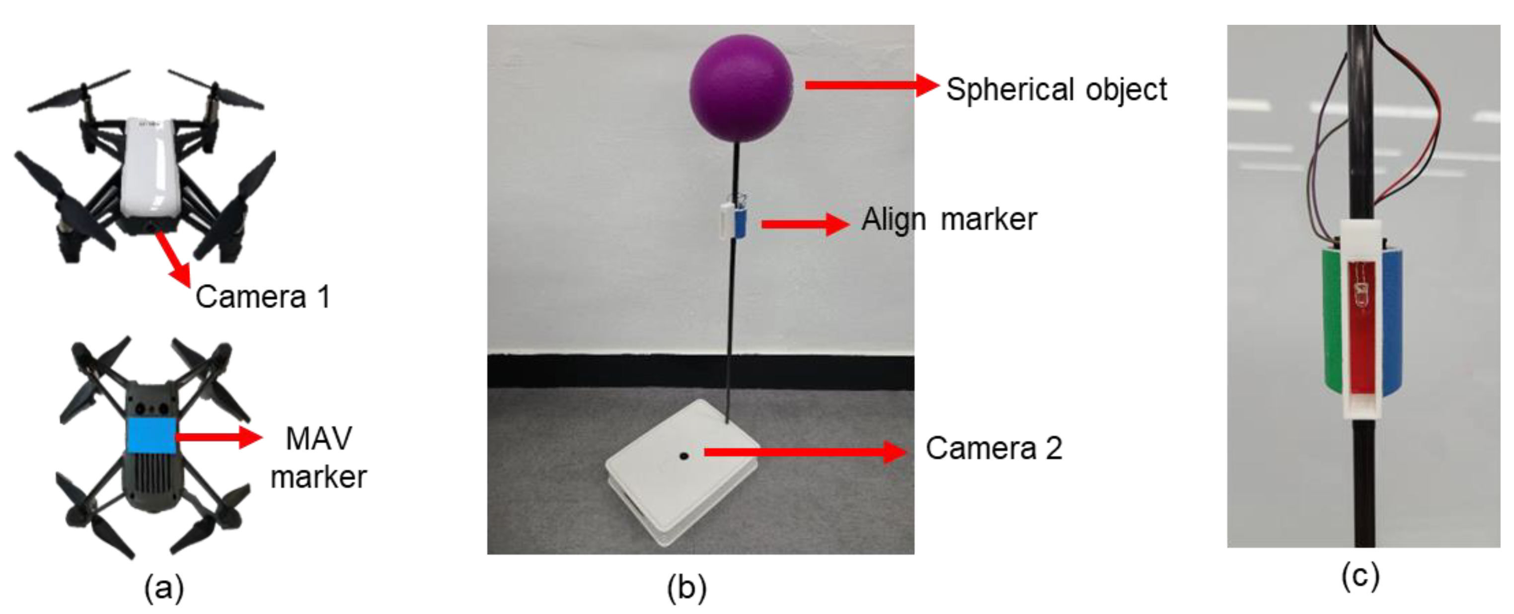
2.1. System Configuration

The MAV used in this study was a DJI TELLO drone (https://www.ryzerobotics.com/tello, accessed on 23 August 2021), which is shown in Figure 1a. This 80-g MAV has an optical flow sensor at the bottom, and a 30 frames per seconds high-definition camera mounted in the frontal direction, hereafter referred to as camera 1. A blue paper is attached to the bottom of the MAV, which can be detected by the platform camera, hereafter referred to as camera 2. The color of the MAV marker was blue because it is an easily distinguishable color indoors. However, if this system is deployed outdoors, green or red can be used to indicate the marker rather than blue, as it is similar to the color of the sky.
Figure 1b shows the landing platform used in the proposed system. It consists of a spherical object, an align marker, and camera 2. The spherical object is necessary for the MAV to search and approach the platform. The align marker is used when the MAV rotates around the platform to determine the exact position of the landing area. Camera 2 provides data regarding the MAV position for landing accuracy enhancement.

2.2. Landing Strategy and MAV Control

The proposed landing procedure is performed as follows:
STEP 1.
The MAV searches the spherical object and yaws until the object is located at the center of the image captured by camera 1.
STEP 2.
The MAV approaches the platform while adjusting its position to keep the spherical object at the center of the image in STEP 1.
STEP 3.
When the MAV is sufficiently close to the platform, it begins to descend in search of the align marker.
STEP 4.
The descending motion stops when the alignment marker is at the center of the image.
STEP 5.
The MAV rotates around the platform according to the color of the align marker.
STEP 6.
Camera 2 detects the marker under the MAV and acknowledges its position.
STEP 7.
The MAV is guided to the target location on the platform and lands.
When the MAV approaches the platform (STEP 2), the radius of the spherical object in the image is detected and is used to estimate the distance between the MAV and the platform. The align marker used in STEP 5 is a cylindrically shaped object; three different-colored markers are located on its surface. Thus, depending on the detected marker color, the MAV determines the direction of rotation. To improve the accuracy of the alignment, the marker is designed as follows: when the MAV is perfectly aligned with the platform, only the center marker is captured, and the other two markers are invisible. To this end, thin walls are attached around the center marker, as shown in Figure 1c. This design enables the MAV to detect only the center marker when it is aligned. However, the shadow of the thin wall falls on the center marker. Thus, a light-emitting diode (LED) was installed near the third marker to prevent detection failure. For the detection of the align marker and the marker attached to the bottom of the MAV (STEP 5 and 6), HSV filter-based detection was used. Figure 2 illustrates the overall landing procedure.
The MAV is controlled by seven velocity commands (forward, backward, left, right, up, down, and yaw) for maneuvering. Note that the MAV was controlled using the position data (in pixels) from the camera images. For example, when the MAV approaches the platform (STEP 2), the position of the spherical object (in pixels) in the image is selected as the reference position. A proportional-derivative (PD) control was used to allow a swift flight control of the MAV, as shown in Figure 3. Thus, the velocity command u ( t ) can be obtained as
u ( t ) = K p e ( t ) + K d ( e ( t ) e ( t Δ t ) Δ t ) ,
where e ( t ) is the pixel position error at time t, and Δ t is the time interval. K p and K d are the coefficients for the PD control. The values of K p and K d for SETP 2 were determined as 0.2 and 0.09, respectively, and 0.13 and 0.075 for STEP 7.

2.3. Mono-Colored Spherical Object Detection Algorithm

Landing control strongly depends on the performance of the detection algorithm. To reduce the latency of the detection algorithm, a simple detection method could be used (e.g., HSV filtering detection). However, simple detection methods are vulnerable to different illumination conditions. For example, side illumination can create shadows and cause variations in the HSV color space, even for mono-colored target objects. Additionally, backlight can tarnish the color of the target object, which in turn can degrade the performance of the HSV filter-based detection algorithm. Figure 4 shows some situations in which the HSV detection fails (e.g., only a portion of the target object is detected).
To prevent such failures, a new hybrid detection algorithm that provides accurate and robust spherical object detection with low latency was developed in this study. This algorithm is characterized with the following features: integration of color filtering and edge detection algorithm, use of cropped images for low latency, and an adaptive detection strategy robust to variations in lighting conditions.
First, the newly developed algorithm conducts both HSV filtering and the circle Hough transform (CHT) [33]. In general, CHT is more accurate than HSV filtering; however, HSV filtering is faster than CHT. Furthermore, CHT cannot detect a spherical object when there is a large number of edges, which are irrelevant to the spherical object. Moreover, the detection fails when the edge of the object is blurred in the captured image due to the sudden movement of the MAV. To overcome these accuracy and latency issues, both HSV filtering and CHT are used in the new algorithm.
Second, a cropping technique was introduced to reduce the CHT computation time. The classical CHT calculates all edges detected in the entire image. However, if all pixels in the image are investigated for detection, CHT would require a long computation time for real-time MAV control. Thus, in the new algorithm, CHT is applied on a cropped image, not on the entire image. Specifically, a spherical object is detected via HSV filtering, as shown in Figure 5a. If a lighting condition is not desirable for object detection, the HSV filter is likely to detect just a portion of the spherical object; it cannot detect the whole body of the spherical object. Then, a square image is cropped, as shown in Figure 5b. The center of the cropped image is determined as the center position of the object, and its width and height are determined as twice the diameter of the detected object. Next, the position and size of the spherical object are detected via CHT on the cropped image, as shown in Figure 5c. Note that conversion into a grayscale image and a bilateral filter were also used for noise reduction, while preserving the sharp edges of the image. This approach leads to an accurate and fast spherical object detection.
Finally, the new algorithm adaptively determines the size and position of the spherical object based on the following scenarios:
  • Scenario 1. If a sphere is detected via CHT, the size and position estimated by the CHT are used in the control.
  • Scenario 2. If the CHT fails to find a spherical object and the MAV approaches the platform, the position calculated by the HSV filter is used. The radius is determined as the larger value between the radius predicted via HSV filtering and the radius estimated in the previous time. This criterion is required because the radius predicted via HSV filtering is usually smaller than the true radius. This inaccurate radius estimation, which is smaller than the true radius, leads to a very high approaching speed in STEP 2. Consequently, the MAV is likely to collide with the spherical object. To prevent this collision, the radius value is determined as the maximum value between the radius value obtained from HSV filter and the value calculated in the previous time step.
  • Scenario 3. If the CHT fails to find a spherical object and the MAV is yawing in search of the spherical object, the position and radius predicted via HSV filtering are used. Before the initial spherical object detection occurs, image cropping for CHT and radius comparison are unavailable. Thus, in this scenario, the HSV filtering result is used, even though it is inaccurate. Notably, the error in this scenario can be rapidly reduced because the CHT on the cropped image starts to operate when the MAV vision system initially detects the spherical object.
Figure 6 shows the flowchart of the new hybrid detection algorithm with the abovementioned scenarios.
This hybrid detection algorithm (shown in Figure 6) was used to detect the spherical object and not the align marker. During detection of the sphere installed at the landing platform, the distance from the MAV to the sphere is considerable, and other objects can be captured in the image. To reduce the possibility of misdetection, the pass range of the HSV filter must be narrow. However, only a portion of the spherical object would be detected because of this narrow band (for the HSV filter). Thus, cropping, the scenario-based method and CHT were combined to detect the sphere. Meanwhile, during detection of the align marker, the MAV is very close to the station. Thus, the align marker occupies most of the image area, and interference by other objects in the background is very small. A broad HSV range can thus be used for the align marker, hence the hybrid detection algorithm was not necessary.

3. Results

3.1. Spherical Object Detection

The performance of the new detection algorithm was verified under two different lighting conditions: a spherical object in a dark space with directional lighting, as shown in Figure 7(a1), and the same spherical object in a bright space with excessive backlight, as shown in Figure 7(b1). Figure 7(a1,b1) show the HSV filter detection results, and Figure 7(a2,b2) show the results of the new algorithm. Figure 7(a3,b3) represent the estimated radii over time under these lighting conditions. While the HSV filter captures a small portion of the spherical object, the new algorithm accurately detects it. Moreover, the radius calculated by the HSV filter strongly fluctuates over time, which leads to unstable MAV control. However, the new algorithm provides stable results. The mean absolute error (MAE) of the spherical object detection is presented in Table 1. Additional experiments were conducted to consider the effects of flickering lights and other surrounding objects on the hybrid detection algorithm. Details on the additional experiments are provided in Supplementary material (Figures S1–S3). These results suggest that the new algorithm can provide accurate and robust detection of spherical objects under harsh lighting conditions.

3.2. Experimental Setting

In this study, the MAV is connected to a laptop for control via a wireless LAN, and the platform camera is connected to the laptop via a USB cable. Figure 8 shows the experimental setting used to validate the proposed landing system. Although a laptop was used to operate the object detection algorithm in the present study, in future work, the proposed algorithm can be executed on the MAV on-board computing as this algorithm requires a small amount of computational resources.
To test the effects of the MAV starting position on the landing results, the MAV started at eight different locations (i.e., L1–L8), as shown in Figure 8a. The distance between the MAV starting position and the platform was set to 8 m; this distance was chosen because it was similar to the GPS navigation error. Initially, the angle between the MAV and the platform was set as 90° with respect to the orientation of the platform in order to test the search motion (STEP 1); the setting direction of the MAV is represented by arrows in Figure 8a. Ten experiments were conducted at each initial position while recording the time required for autonomous landing and the landing spot. The supplementary videos (Video S1) show the entire landing procedure.

3.3. Results of the Landing Experiments

In 80 landing experiments, the MAV successfully landed on the A4 paper-sized platform in all trials. The landing spots were recorded by marking the center of the MAV on the A4-sized platform, as shown in Figure 9. The black circle represents the reference position for landing, and the red crosses represent the actual landing spots. The MAE between the target position and the landing spots was 2.7 cm, and the standard deviation (SD) was 1.4 cm. The MAE and SD values for each initial position are listed in Table 2. These results show that the proposed landing system achieved a 2–3 cm landing error, which is very small considering the platform size.
Table 3 lists the average time required for each step in the entire landing procedure, as well as the total landing time. The times are very similar for each step regardless of the starting position, except for STEP 5. Because this step corresponds to MAV alignment, it is evident that this duration difference significantly depends on staring position. The approaching step (i.e., STEP 2) required more time. The entire landing procedure was completed in 23–30 s on average.

4. Discussion and Conclusions

Visual data can be beneficial for autonomous landing because it can resolve issues related to inaccurate GPS navigation and GPS-denied environments. This study proposed a new autonomous landing system optimized for MAVs. The developed landing platform was designed with various equipment to assist landing: a spherical object for searching from long distances, align markers, and a camera for position adjustment. A new algorithm was developed to improve the detection of spherical objects on the platform.
It was verified that the new detection algorithm could accurately detect spherical objects under harsh lighting environments. Eighty flight experiments were conducted to validate the performance of the proposed landing system. All landing trials were successful, with an average position error of 2.7 ± 1.4 cm. Moreover, the entire landing procedure (i.e., search, approach, and landing) was completed in a short time (26 s on average). Therefore, the proposed landing system enables the MAV to perform robust and precise landing; the MAV requires only a single RGB vision camera and does not require any additional sensors.
Although a laptop was used to operate the object detection algorithm in the present study, in future work, the proposed algorithm can be executed on the MAV on-board computing as this algorithm requires minimal computational resources. Specifically, the entire computation (i.e., feedback control of the MAV and image processing on the images from camera 1 and 2) was conducted on a laptop with Intel Core i5 3317U (dual core, 1.7 GHz). In the future, the detection algorithm can be implemented in an MAV with an onboard computing device. For example, a microcontroller with quad core Cortex-A72 can be used because its computing power is similar to the laptop used in this study. Furthermore, it is worth noting that the microcontroller in the MAV does not need to conduct detection for the align marker. Because this process aims to detect three markers simultaneously, it requires heavier computation. This process can be performed by the laptop connected to the landing platform. Therefore, in the future, an MAV with onboard computing will be able to achieve a fast and accurate landing in collaboration with the extra computing device embedded in the platform.
Despite the high accuracy and success rate in the experiments, there are some limitations to be considered. The detection algorithm depends on the color of the target object. Thus, if an object has a similar color to that of the target object, the algorithm can erroneously predict the other spherical object as the target object. The disrupting object, which has a similar color to that of the target object, is mostly smaller than the target din images. Thus, to reduce the misdetection, the algorithm was designed to predict the largest object as the target object among the candidate objects with similar colors. Details on this limitation are provided in Supplementary Material. Moreover, because all the experiments were conducted indoors, outdoor environmental conditions, such as wind and weather, can degrade the landing performance. Additional experiments are necessary to verify the proposed landing system under various weather conditions. The MAV can also collide with a spherical object during searching. This issue can be addressed by adjusting the position of this object. For example, when the MAV is close to the object, the object can be automatically moved away from the platform (or move downward) to prevent collisions.

Supplementary Materials

The following are available online at https://www.mdpi.com/article/10.3390/app11188555/s1, Video S1: Autonomous landing of MAV. Figure S1: Detection result in the presence of flickering light. The red and green circle represent the detection via HSV filtering only and the detection obtained with the proposed algorithm, respectively. Figure S2: Effect of overlapping object on detection. The green circle edge represents the detection via the hybrid detection algorithm. Figure S3: Results of the additional experiment. The purple ball in the center is the target subject, and the green edge represents the detection result.

Author Contributions

Conceptualization, W.N.; methodology, D.L.; software, D.L.; validation, D.L. and W.P.; formal analysis, D.L.; investigation, D.L.; resources, D.L.; data curation, W.P.; writing—original draft preparation, D.L.; writing—review and editing, W.N.; visualization, D.L.; supervision, W.N.; project administration, W.N.; funding acquisition, W.N. All authors have read and agreed to the published version of the manuscript.

Funding

This research was supported by the National Research Foundation of Korea (NRF) grant funded by the Korea government (MSIT) (No. 2021R1A4A3030268), the Korea Medical Device Development Fund grant funded by the Korea government(the Ministry of Science and ICT, the Ministry of Trade, Industry and Energy, the Ministry of Health & Welfare, the Ministry of Food and Drug Safety) (No. 1711138421, KMDF_PR_20200901_0194), and Chung-Ang University Graduate Research Scholarship in 2021.

Data Availability Statement

The data supporting the results presented herein are available from the corresponding author upon reasonable request.

Conflicts of Interest

The authors declare no conflict of interest.

References

  1. Girard, A.R.; Howell, A.S.; Hedrick, J.K. Border patrol and surveillance missions using multiple unmanned air vehicles. In Proceedings of the IEEE Conference on Decision and Control (CDC), Nassau, Bahamas, 14–17 December 2004; Volume 1, pp. 620–625. [Google Scholar]
  2. Semsch, E.; Jakob, M.; Pavlicek, D.; Pechoucek, M. Autonomous UAV Surveillance in Complex Urban Environments. In Proceedings of the IEEE/WIC/ACM International Joint Conference on Web Intelligence and Intelligent Agent Technologies, Milan, Italy, 15–18 September 2009; Volume 2, pp. 82–85. [Google Scholar]
  3. Mathew, N.; Smith, S.L.; Waslander, S.L. Planning Paths for Package Delivery in Heterogeneous Multirobot Teams. IEEE Trans. Autom. Sci. Eng. 2015, 12, 1298–1308. [Google Scholar] [CrossRef]
  4. Waharte, S.; Trigoni, N. Supporting search and rescue operations with UAVs. In Proceedings of the International Conference on Emerging Security Technologies, Canterbury, UK, 6–7 September 2010; pp. 142–147. [Google Scholar]
  5. Tomic, T.; Schmid, K.; Lutz, P.; Domel, A.; Kassecker, M.; Mair, E.; Grixa, I.L.; Ruess, F.; Suppa, M.; Burschka, D. Toward a fully autonomous uav: Research platform for indoor and outdoor urban search and rescue. IEEE Robot. Autom. Mag. 2012, 19, 46–56. [Google Scholar] [CrossRef] [Green Version]
  6. Menouar, H.; Guvenc, I.; Akkaya, K.; Uluagac, A.S.; Kadri, A.; Tuncer, A. UAV-Enabled Intelligent Transportation Systems for the Smart City: Applications and Challenges. IEEE Commun. Mag. 2017, 55, 22–28. [Google Scholar] [CrossRef]
  7. Kumar, V.; Michael, N. Opportunities and challenges with autonomous micro aerial vehicles. Int. J. Robot. Res. 2012, 31, 1279–1291. [Google Scholar] [CrossRef]
  8. Floreano, D.; Wood, R.J. Science, technology and the future of small autonomous drones. Nature 2015, 521, 460–466. [Google Scholar] [CrossRef] [PubMed] [Green Version]
  9. Shakhatreh, H.; Sawalmeh, A.H.; Al-Fuqaha, A.I.; Dou, Z.; Almaita, E.K.; Khalil, I.M.; Othman, N.S.; Khreishah, A.; Guizani, M. Unmanned Aerial Vehicles (UAVs): A Survey on Civil Applications and Key Research Challenges. IEEE Access 2019, 7, 48572–48634. [Google Scholar] [CrossRef]
  10. Santana, L.; Brandão, A.; Sarcinelli-Filho, M. Outdoor waypoint navigation with the AR.Drone quadrotor. In Proceedings of the International Conference on Unmanned Aircraft Systems (ICUAS), Denver, CO, USA, 9–12 June 2015; pp. 303–311. [Google Scholar]
  11. Kwak, J.; Sung, Y. Autonomous UAV Flight Control for GPS-Based Navigation. IEEE Access 2018, 6, 37947–37955. [Google Scholar] [CrossRef]
  12. Saripalli, S.; Montgomery, J.F.; Sukhatme, G.S. Visually-Guided Landing of an Unmanned Aerial Vehicle. IEEE Trans. Robot. Autom. 2003, 19, 371–381. [Google Scholar] [CrossRef] [Green Version]
  13. Lange, S.; Sünderhauf, N.; Protzel, P. A vision based onboard approach for landing and position control of an autonomous multirotor UAV in GPS-denied environments. In Proceedings of the IEEE International Conference on Advanced Robotics, Munich, Germany, 22–26 June 2009; pp. 1–6. [Google Scholar]
  14. Yang, S.; Scherer, S.A.; Zell, A. An onboard monocular vision system for autonomous takeoff, hovering and landing of a micro aerial vehicle. J. Intell. Robot. Syst. 2013, 69, 499–515. [Google Scholar] [CrossRef] [Green Version]
  15. Cho, A.; Kang, Y.S.; Park, B.J.; Yoo, C.S.; Koo, S.O. Altitude integration of radar altimeter and GPS/INS for automatic takeoff and landing of a UAV. In Proceedings of the International Conference on Control, Automation and Systems, Venice, Italy, 26–29 October 2011. [Google Scholar]
  16. Nguyen, T.H.; Cao, M.; Nguyen, T.M.; Xie, L. Post-mission autonomous return and precision landing of uav. In Proceedings of the 15th International Conference on Control, Automation, Robotics and Vision (ICARCV), Singapore, 18–21 November 2018; pp. 1747–1752. [Google Scholar]
  17. Kong, W.; Zhang, D.; Wang, X.; Xian, Z.; Zhang, J. Autonomous landing of an UAV with a ground-based actuated infrared stereo vision system. In Proceedings of the IEEE/RSJ International Conference on Intelligent Robots and Systems, Tokyo, Japan, 3–7 November 2013; pp. 2963–2970. [Google Scholar]
  18. Gui, Y.; Guo, P.; Zhang, H.; Lei, Z.; Zhou, X.; Du, J.; Yu, Q. Airborne vision-based navigation method for UAV accuracy landing using infrared lamps. J. Intell. Robot. Syst. 2013, 72, 197–218. [Google Scholar] [CrossRef]
  19. Dobrev, Y.; Dobrev, Y.; Gulden, P.; Lipka, M.; Pavlenko, T.; Moormann, D.; Vossiek, M. Radar-Based High-Accuracy 3D Localization of UAVs for Landing in GNSS-Denied Environments. In Proceedings of the 2018 IEEE MTT-S International Conference on Microwaves for Intelligent Mobility (ICMIM), Munich, Germany, 15–17 April 2018; pp. 1–4. [Google Scholar]
  20. Pavlenko, T.; Schütz, M.; Vossiek, M.; Walter, T.; Montenegro, S. Wireless Local Positioning System for Controlled UAV Landing in GNSS-Denied Environment. In Proceedings of the 2019 IEEE 5th International Workshop on Metrology for AeroSpace (MetroAeroSpace), Torino, Italy, 19–21 June 2019; pp. 171–175. [Google Scholar]
  21. Pebrianti, D.; Kendoul, F.; Azrad, S.; Wang, W.; Nonami, K. Autonomous hovering and landing of a quad-rotor micro aerial vehicle by means of on ground stereo vision system. J. Syst. Des. Dynam. 2010, 4, 269–284. [Google Scholar] [CrossRef] [Green Version]
  22. Engel, J.; Sturm, J.; Cremers, D. Camera-based navigation of a low-cost quadrocopter. In Proceedings of the 2012 IEEE/RSJ International Conference on Intelligent Robots and Systems, Vilamoura, Portugal, 7–12 October 2012; pp. 2815–2821. [Google Scholar]
  23. Fraundorfer, F.; Heng, L.; Honegger, D.; Lee, G.H.; Meier, L.; Tanskanen, P.; Pollefeys, M. Vision-based autonomous mapping and exploration using a quadrotor MAV. In Proceedings of the 2012 IEEE/RSJ International Conference on Intelligent Robots and Systems (IROS), Vilamoura, Algarve, Portugal, 7–12 October 2012; pp. 4557–4564. [Google Scholar]
  24. Yang, S.; Scherer, S.A.; Yi, X.; Zell, A. Multi-camera visual SLAM for autonomous navigation of micro aerial vehicles. Robot. Autom. Syst. 2017, 93, 116–134. [Google Scholar] [CrossRef]
  25. Borowczyk, A.; Nguyen, D.T.; Nguyen, A.P.V.; Nguyen, D.Q.; Saussié, D.; Ny, J.L. Autonomous landing of a multirotor micro air vehicle on a high velocity ground vehicle. IFAC Pap. Online 2017, 50, 10488–10494. [Google Scholar] [CrossRef]
  26. Wang, Z.; She, H.; Si, W. Autonomous landing of multi-rotors UAV with monocular gimbaled camera on moving vehicle. In Proceedings of the IEEE International Conference on Control & Automation (ICCA), Ohrid, Macedonia, 3–6 July 2017; pp. 408–412. [Google Scholar]
  27. Dotenco, S.; Gallwitz, F.; Angelopoulou, E. Autonomous approach and landing for a low-cost quadrotor using monocular cameras. In Proceedings of the European Conference on Computer Vision Workshops, Zurich, Switzerland, 6–12 September 2014; pp. 209–222. [Google Scholar]
  28. Sani, M.F.; Karimian, G. Automatic Navigation and Landing of an Indoor AR. Drone Quadrotor Using ArUco Marker and Inertial Sensors. In Proceedings of the International Conference on Computer and Drone Applications (IConDA), Kuching, Malaysia, 9–11 November 2017; pp. 102–107. [Google Scholar]
  29. Ren, S.; He, K.; Girshick, R.; Sun, J. Faster R-CNN: Towards Real-Time Object Detection with Region Proposal Networks. IEEE Trans. Pattern Anal. Mach. Intell. 2016, 39, 1137–1149. [Google Scholar] [CrossRef] [PubMed] [Green Version]
  30. Dai, J.; Li, Y.; He, K.; Sun, J. R-FCN: Object detection via region-based fully convolutional networks. In Proceedings of the Advances in Neural Information Processing Systems, Barcelona, Spain, 5–10 December 2016; pp. 379–387. [Google Scholar]
  31. Redmon, J.; Farhadi, A. Yolov3: An incremental improvement. arXiv 2018, arXiv:1804.02767. [Google Scholar]
  32. Liu, W.; Anguelov, D.; Erhan, D.; Szegedy, C.; Reed, S.; Fu, C.; Berg, A.C. SSD: Single Shot MultiBox Detector. In Proceedings of the European Conference on Computer Vision—ECCV, Amsterdam, The Netherlands, 8–16 October 2016; pp. 21–37. [Google Scholar]
  33. Kerbyson, D.J.; Atherton, T.J. Circle detection using Hough transform filters. In Proceedings of the Fifth International Conference on Image Processing and its Applications, Edinburgh, UK, 4–6 July 1995; pp. 370–374. [Google Scholar]
Figure 1. MAV and landing system. (a) MAV with camera and bottom marker; (b) landing platform with a spherical object, align marker, and camera; (c) align marker.
Applsci 11 08555 g001
Figure 2. Proposed autonomous landing procedure.
Applsci 11 08555 g002
Figure 3. MAV PD control.
Applsci 11 08555 g003
Figure 4. Inaccurate detection with HSV filtering under harsh lighting conditions. (a) Dark space with insufficient directional lighting; (b) bright space with excessive backlight.
Applsci 11 08555 g004
Figure 5. Sequence of the newly developed algorithm. (a) Original image captured by the MAV vision system; (b) cropped image using the HSV filtering result; (c) final spherical object detection using the detection algorithm. The red and green circles represent the detected result of the HSV filter and CHT, respectively.
Applsci 11 08555 g005
Figure 6. Flowchart of the new hybrid detection algorithm; x h ( t ) , y h ( t ) , and r h ( t ) denote the position along the x-axis, the position along the y-axis, and radius in the image calculated by the HSV filter at time t , respectively. x c ( t ) , y c ( t ) , and r c ( t ) are the position along the x-axis, the position along the y-axis, and radius in the image calculated by CHT at time t , respectively. x e ( t ) , y e ( t ) , and r e ( t ) are the final values of x, y, and r estimated by the new algorithm at time t , respectively. r e ( t Δ t ) is the radius estimated in the previous time.
Applsci 11 08555 g006
Figure 7. Detection results under harsh lighting conditions. (a) Results in a dark space with directional light; (b) Results in a bright space with excessive backlight.
Applsci 11 08555 g007
Figure 8. Experimental setup of the autonomous landing system. (a) Configuration of the landing experiments with arrows at each location showing the direction where the MAV is facing; (b) platform and MAV at the start of the autonomous landing control.
Applsci 11 08555 g008
Figure 9. Landing spots on the A4-paper-sized platform; the black circle represents the reference landing position, and the red crosses are the actual landing spots.
Applsci 11 08555 g009
Table 1. MAE of the HSV Filter and the newly developed algorithm.
Radius MAE (Pixel)Dark SpaceBright Space
HSV filter34.5921.94
New algorithm1.550.89
Table 2. MAV landing spot statistics. Ten trials were conducted in every direction.
L1L2L3L4L5L6L7L8Total
MAE (cm)3.72.12.92.12.93.02.72.72.7
SD (cm)1.71.80.90.90.91.11.31.41.4
Table 3. Average time required during the landing procedure. Ten trials were conducted for every direction.
Initial PositionSTEP 1STEP 2STEP 3 & 4STEP 5STEP 6Total
L12.59.42.40.59.123.9
L22.58.52.84.07.325.1
L32.68.93.06.05.726.1
L42.58.92.66.55.025.4
L52.69.62.610.15.029.9
L62.510.52.67.24.927.8
L72.49.22.35.85.224.8
L82.410.42.33.26.424.6
Average2.59.42.65.46.126.0
Units: s.
Publisher’s Note: MDPI stays neutral with regard to jurisdictional claims in published maps and institutional affiliations.

