Article

Functionally Graded Plate Fracture Analysis Using the Field Boundary Element Method

Engineering Department, University of Campania “Luigi Vanvitelli”, 81031 Aversa (CE), Italy
*
Author to whom correspondence should be addressed.
Appl. Sci. 2021, 11(18), 8465; https://doi.org/10.3390/app11188465
Submission received: 20 July 2021 / Revised: 30 August 2021 / Accepted: 4 September 2021 / Published: 12 September 2021
(This article belongs to the Topic Advances on Structural Engineering)

Abstract

:
This paper describes the Field Boundary Element Method (FBEM) applied to the fracture analysis of a 2D rectangular plate made of Functionally Graded Material (FGM) to calculate Mode I Stress Intensity Factor (SIF). The case study of this Field Boundary Element Method is the transversely isotropic plane plate. Its material presents an exponential variation of the elasticity tensor depending on a scalar function of position, i.e., the elastic tensor results from multiplying a scalar function by a constant taken as a reference. Several examples using a parametric representation of the structural response show the suitability of the method that constitutes a Stress Intensity Factor evaluation of Functionally Graded Materials plane plates even in the case of more complex geometries.

1. Introduction

In the recent past, a new class of composite materials, namely Functionally Graded Materials (FGM), has attracted researchers and designed to satisfy multiphysical requests, by combining different materials into one, resulting in a continuous variable material. The main difference of FGM from traditional composites is that component properties are combined to achieve an intermediate behavior between the constituents. When the FGM is used at the interface between two materials, it enables a continuous transition from one material to the other avoiding the discontinuity of the response at the interface level. In other words, FGMs have been presented as an alternative to laminated composite materials that exhibit a discrepancy in properties at material interfaces. This material discontinuity in laminated composite materials leads to large interlaminar stresses and the possibility of crack initiation and propagation. Continuous transition greatly influences crack propagation at the interface level and avoids or reduces debonding and slip of layers [1,2,3,4].
As a common example, metal/ceramic composites incorporate the excellent corrosion resistance and insulating properties of ceramics with the high strength and bonding ability of metals without requiring a high thermal stress rate. However, ceramics, in contrast to metals, have a fragile nature so crack-like defects are usually induced under service load conditions. Hence, FGMs are widely used in research and the manufacturing industry for optimization and design [5,6].
For the evaluation of cracks induced by several loading conditions, many theories and numerical applications have emerged over the years and as have many parameters to describe the fractures. The Stress Intensity Factor, SIF, as a measure of the stress concentration at the crack tip that is responsible for the crack propagation is generally assumed as an important parameter to determine the safety of a cracked structure [7].
As previously mentioned, the increasing interest in cracks in Functionally Graded Materials (FGM) gave rise to several methods such as the Weight Function approach [8,9], Energy Release Method [10], and others.
The present work aimed to apply the boundary element method to heterogeneous material fractures. The BEM applied to fracture mechanics is split into two different approaches. The first, the dual boundary element method, is based on two dual integral equations, the first based on the displacement Somigliana identity and the second obtained through the projection on the boundary of the gradient of the first one resulting in a traction identity [11]. The reason for such a model is based on the fact that the displacement equation should be collocated on both sides of the crack that produced the linear dependence of the equations. To avoid the singularity, the two different primary and dual equations can be placed on each edge of the fracture line. The disadvantage of this approach is the presence of hypersingular integrals. The second strategy, to avoid the dual approach, uses a multizone formulation where the structure is divided into parts along the crack line so that different displacement integral equations are formulated on the separate regions and coupling is obtained using boundary conditions at the common points and on the crack edges [12]. The formulation proposed in the present work is based on the displacement integral equation specified for FGMs. The fracture model is borrowed from the multizone approach; in particular, the proposed examples deal with symmetrical structures where the crack belongs to one edge. A multizone approach for FGM has been proposed in [13]; this formulation can be extended to fracture mechanics with no complication. A simple approach has been chosen here to focus on the relevant aspects of the SIF calculation.
The calculation used an enriched formulation of the boundary element method with field terms that account for the variation of material elasticity [13,14,15,16,17]. Using the formulation, the application of Elastic Fracture Mechanics (EFM) is shown to calculate the Stress Intensity Factor under Mode I crack propagation.
The calculations followed the traditional formulation for EFM where it is supposed that around the crack tip the elasticity of the material is constant within the small region of stress concentration. The interface, the joints, or the surfaces, have great importance in graded material because the stress is usually limited to these locations. In these cases, the specific zone is the so-called “graded zone” and if the volume fractions of the constituent materials change by a certain smooth function, the material is defined as a functionally graded material, FGM [18,19,20]. Furthermore, several benchmarks and reports of models using Linear Elastic Fracture Mechanics (LEFM) are presented in [21,22]. Moreover, it is possible to evaluate other aspects of fractures in a microscale approach through anisotropic 2D models.
For cracked FGMs with general geometry and loading conditions, advanced numerical methods must be applied because of the mathematically complex nature of the governing partial differential equations with variable coefficients, and because the most available analytical methods can only be successfully applied to cracked FGMs with very simple geometry and loading conditions.
A study that considered the plane elasticity problem for an inhomogeneous medium containing a crack and with the derivative of the displacement of the crack surface as a density function with a simple Cauchy-type kernel was developed in [23]. The singular nature of the crack tip stress field in a nonhomogeneous medium having a shear modulus was not affected with a discontinuous derivative as shown in [24]. Periodic surface cracking and the associated problem of stress and energy release and the problem of stress concentration and delamination crack initiation and growth under residual or thermal stress were investigated in [25]. The elastic stress and displacement fields near a crack tip in a two-dimensional inhomogeneous cracked body were derived using an extension of the Williams’ eigenfunction expansion technique in [26]. An inhomogeneous elastic medium containing a crack arbitrarily oriented to the direction of the property gradient was considered in [27]. Local homogeneity and the small-scale inelasticity of brittle materials, where the toughness was taken to be independent of direction, was investigated in [28,29]. Moreover, the discretized material property variation assigning different homogeneous elastic properties to each element was used in [30]. Several numerical simulations by varying the location of the crack in the graded region for different material gradients were employed in [31]. The mixed-mode stress intensity factors obtained employing the domain integrals as a postprocessing step in the extended finite element method (XFEM) have been provided in [32,33,34,35]. A multiple iso-parametric finite element method to compute stress intensity factor was employed in [36,37]. A numerical crack analysis of functionally graded two-dimensional materials using an integral boundary equation method linked to the Galerkin method to overcome hypersingular integral boundary equations was performed by [38,39]. Extensive transient dynamic crack analyses for a functionally graded material (FGM) by using a hypersingular time-domain boundary integral equation method were presented in [40,41,42,43]. A layer discretization technique to approximate material inhomogeneity and a so-called generalized boundary element method based on the Kelvin solution was used in a numerical examination in [44]. The symmetric Galerkin boundary element method (SGBEM) using nonuniform rational B-splines (NURBS) for both geometry and field variables approximation was presented by [45,46,47]. Other numerical solutions have been investigated recently concerning the vibration analysis of nanocomposite conical shells [48]. In the present paper, the plate problem under in-plane loading is analyzed in small-displacement theory. An analysis of large displacements in the bending of tapered plate and shells and FGM cylindrical shells where the variability of the material develops toward the thickness as well as in the middle plane of the plate can be found in [49,50,51,52,53,54].
This paper is organized as follows: In Section 2, the mathematical framework of the applied model, geometry, variation of mechanical properties, applied loading, and the fundamentals of integral equations for FGMs are presented. Section 3 details the result of the present FBEM in terms of displacements along x and y directions highlighting the differences between the FGM cases and the homogeneous one. In addition, an intercase comparison is shown regarding the stress intensity factors (SIFs) of mode I. In Section 4, all results, previously shown, and final considerations are discussed as well as some observations and suggestions for further research.

2. Materials and Methods

This section aims to introduce the fundamentals of integral equations applied to FGM through a mixed field and boundary approach. After a brief description of the mechanical behavior of FGM within the framework of continuum mechanics, the integral formulation of equilibrium is described. The proof originates from the Somigliana identity specifically for materials for which there is no analytic fundamental solution. Betti’s reciprocity theorem is transformed using a sample material whose fundamental equation is known. The resultant equation includes internal variables that cannot be simplified in addition to the ordinary boundary variables. This yields a combined field and boundary integral equation method.
The structure under consideration is constituted by a solid occupying a domain V . The points of the solid undergoes a deformation described by the displacement vector field u i ( x ) which is assumed to be infinitesimal. In the following, the indicial tensor notation is used where subscripts denote the vector and the tensor components to a reference frame. Moreover, a comma followed by a subscript denotes the partial derivative with respect to the component direction of the index. Finally, the sum on repeated indexes on a monomial is subtended.
The structure is subjected to body forces b i ( x ) and traction t i ( x ) on the boundary. The traction is prescribed on the loaded boundary V f where displacement is unknown, on the constrained boundary V u = V \ V f , appropriate description of the mechanical problem requires that the displacement be prescribed and traction is unknown.
The elastic constitutive law of the material is governed by a fourth-order elastic tensor that has the form:
σ i j ( x ) = C i j h k ( x )   ε h k ( x )
where σ i j   ( x ) is the Cauchy stress tensor and ε h k ( x ) = u h , k ( x ) + u k , h ( x ) 2 is the infinitesimal Green–Lagrange strain tensor.
The material constituting the structure is assumed to be hyperelastic, hence the constitutive tensor in Equation (1) has the usual symmetries that ensure that the strain energy be conservative and that the stress and the strain be symmetrical:
C i j h k ( x ) = C h k i j ( x ) = C j i h k ( x ) = C i j k h   ( x )
The equilibrium equation of the structure, in terms of displacement, u i ( x ) is:
( C i j h k ( x ) u h , k ( x ) ) , j + b i ( x ) = 0
Let us consider u l i * ( x , y ) the displacement at a point x of the elastic infinite space where elasticity is described by a constant elastic tensor C i j h k 0 , due to a one-point force acting at point y.
Let us introduce the displacement field u l i * ( x , y ) resulting from Kelvin’s solution of the elastic space at point x when the unit point force acts at point y . Considering the weak form of Equation (3) obtained through weighted residuals and using as weight function the u l i * ( x , y ) of Kelvin’s solution as previously mentioned, the following Field Boundary Integral equation results. A detailed derivation of the equation can be found in [17]:
( γ δ l h + A l h ) u h = V t h u l h * d S P V V γ t l h * u h d S + V b h u l h * d V + V γ σ l h k * ε h k p d V + V σ l h k * γ , h u k d V V t ^ l h * u h d S + P V V b ^ l h * u h d V
where
A l h = L i j h k ( y ) J l i j k σ t ^ ˜ l h * = L i j h k ε l i j * n k b ^ l h * = ( L i j h k ε l i j * ) , k
and
L i j h k ( x ) = C i j h k ( x ) γ ( x ) C i j h k o
where J l i j k σ ( y ) is a numerical coefficient depending on the boundary regularity at the collocation point y that arises from the Cauchy principal value integration of the singular kernels of the weak equations, which differs from the standard BEM because of the presence of volume singular integrals that depend on the difference from the material constituting the actual problem and the material of the reference elastic space used in the reciprocal theorem, namely the variable elastic-like tensor L i j h k . The L i j h k accounts for the variability of the Poisson ratio and of the anisotropy of the material; in particular, it can be constant, although anisotropic, in order to consider an anisotropic material integral equation using the isotropic fundamental solution as well.
The constant Poisson case that traduces the constant anisotropy class of the material is described by vanishing L i j h k .   We define a ‘scalar graded material’, the material whose elastic tensor depends on a scalar function γ ( x ) and on a reference constant elastic tensor C i j h k 0 . Such variability corresponds to a simple scalar variation of the elastic modulus; it preserves the isotropy class of the elastic tensor and allows some simplification of the Equation (4). In this case, one can assume Kelvin’s fundamental solution described by the same tensor C i j h k 0 , then Equation (4) becomes [20,37]:
[ A l i ( y ) + γ ( y ) δ l i ] u i ( y ) = V b i ( x )   u l i * ( x , y )   d V + V t i ( x )   u l i * ( x , y ) d S V γ ( x )   t l i * ( x , y )   u i ( x ) d S + V σ l h k * ( x , y )   γ , h ( x )   u k ( x )   d V
In particular, u i ( x ) and t i ( x ) are the displacements and tractions on the boundary S. The terms u l i * ( x , y ) and t l i * ( x , y ) represent the displacements and tractions of Kelvin’s solution. In the same manner, we denote with ε l h k * ( x , y ) and σ l h k * ( x , y ) the strain and the stress due to Kelvin’s solution displacements and tractions. The numerical solution of Equation (7) gives the displacement field of the structure, which is used to calculate the displacement at the crack tip. Equation (7) has been discretized using quadratic iso-parametric three nodes line elements for the boundary and eight nodes plane elements for the interior, namely volume integrals. The equation has been collocated on the element nodes producing as many equations as the number of nodal unknown displacement and traction components, provided prescribed boundary data have been accounted for. For the treatment of the integral of singular kernels, ad hoc numerical quadrature has been used for the weak singular boundary integrals concerning u l i * ( x , y ) ; the strong singular boundary integrals concerning t l i * ( x , y ) have been calculated by the rigid body motion technique [55,56]. The proposed formulation was applied to symmetrical 2D plates in plane stress where the crack was modeled using a single line, so no dual equation was needed, nor did hypersingular integrals occur. Another kind of strategy for crack modeling would consist of multiregion discretization that avoids hypersingular integration as well [20]. In fact, in the present paper, to overcome the hypersingular integration, symmetric quarter plate geometry, as depicted in Figure 1, was considered varying material properties and increasing crack length also in the case of homogeneous material. Then, the results between the proposed method (FBEM) with the classical Finite Element Method were compared, showing a good agreement in terms of stresses, strains, and displacements of the proposed formulation and the FEM benchmark. Moreover, starting from the displacement variation, due to different crack tip geometry and material properties, the SIF for all cases was computed. The displacement at the crack tip was extrapolated using a radial expansion in a standard form curve fitting [57]:
u y ( r ) r = C 1 + C 2 r
where u y ( r ) is the Mode I displacement of a nodal point and r is the distance from the crack tip. Coefficients C 1 and C 2 are coefficients to be determined by minimizing the difference between (7) and numerical solution given by (8). The numerical value of SIF is calculated assuming, that within a small neighborhood of the crack tip, the elastic modulus of the material is E t and ν is the Poisson ratio both assumed to be constant. With these considerations the SIF has the usual displacement dependency form:
K I = 2 π E t 4 ( 1 ν 2 ) l i m r 0 u y ( r ) r = 2 π E t 4 ( 1 ν 2 ) C 1

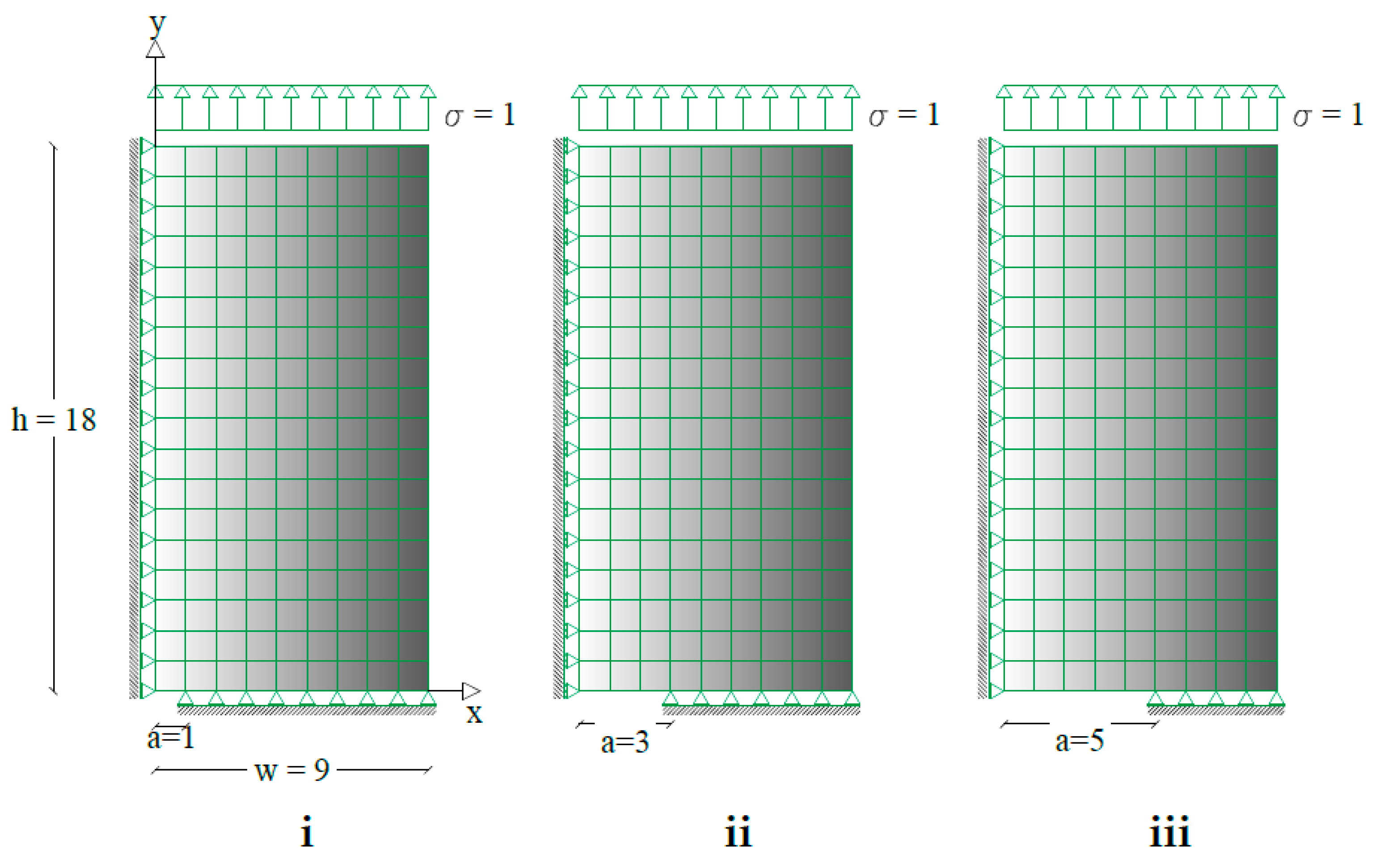
2.1. Mesh and Constraints

The described method was applied to a quarter of a rectangular plate due to symmetry. The plate has length w and height h = 2 w , with a crack at the center aligned to the short plate side. The crack length is a . Figure 1, shows the mesh and boundary conditions of the analyzed structure. The plate mesh used for FEM analysis was constituted by iso-parametric eight nodes domain elements where the Gauss point quadrature was employed. The same domain elements have been used in FBEM analysis together with three nodes quadratic boundary elements. The plate had null displacement on the nodes with y = 0, outside the crack. The x = 0 side had symmetry constraints. The structure was loaded by a traction σ = 1 along y-direction on the top side. Three different crack lengths were investigated, namely a w = 0.11 ; a w = 0.33 ; and a w = 0.55 .

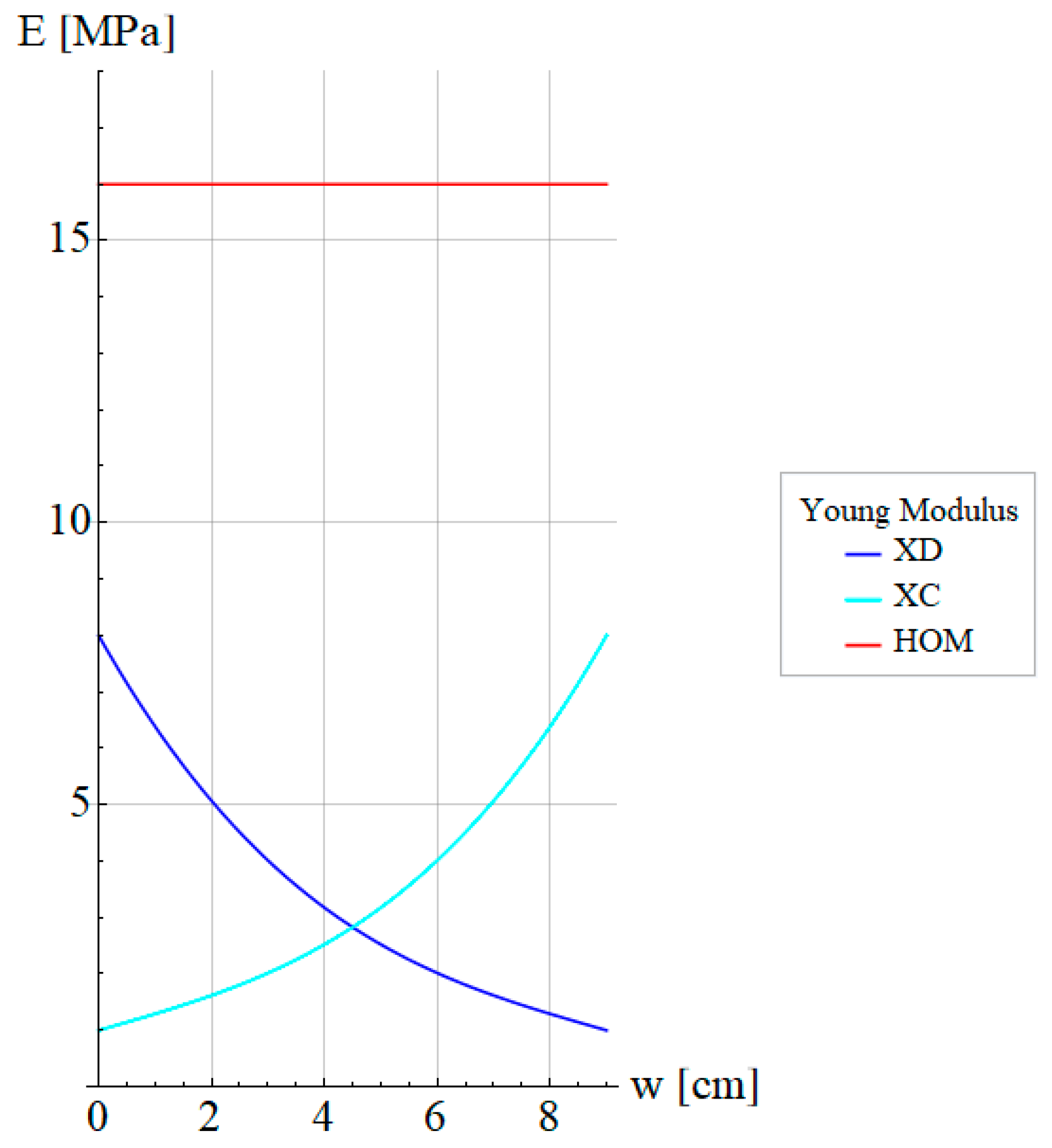
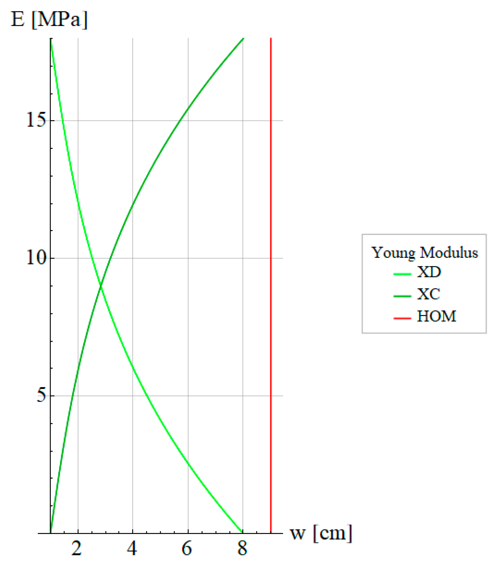
2.2. Material Properties

The material property variation was ascribed to the Elastic Modulus only, i.e., the Poisson ratio was fixed to ν = 0.3 . In particular, the elastic tensor varied through a multiplicative scalar field γ ( x , y ) , and fulfilled the following equation:
E = γ ( x , y ) E 0 C i j h k ( x ) = γ ( x , y ) C i j h k 0
In the proposed example, only the case of variability along with x and y-directions were considered. The reference of the coordinate system had the origin coincident with the center of the crack, consequently, the analyzed specimen had the origin at the leftmost side. Two variabilities were accounted for:
  • X D : Young Modulus decreasing in the x-direction with γ ( x , y ) = γ ( x ) spanning from 8 to 1:
    γ ( x ) = γ ( 0 )   e [ ( x i + w w ) l n ( E 0 E 1 ) ]
  • X C : Young Modulus increasing in the x-direction with γ ( x , y ) = γ ( x ) spanning from 1 to 8:
    γ ( x ) = γ ( 0 )   e [ ( x i w ) l n ( E 0 E 1 ) ]
  • Y D : Young Modulus decreasing in the y-direction with γ ( x , y ) = γ ( y ) spanning from 8 to 1:
    γ ( y ) = γ ( 0 )   e [ ( y i + h h ) l n ( E 0 E 1 ) ]
  • Y C : Young Modulus increasing in the y-direction with γ ( x , y ) = γ ( y ) spanning from 1 to 8:
    γ ( y ) = γ ( 0 )   e [ ( y i h ) l n ( E 0 E 1 ) ]
The numerical calculation was performed assuming a plane strain condition with reference Young Modulus equal to E 0 = 10 3 MPa, Poisson ratio ν = 0.3 , and crack length variation equal to a w = 0.11 ,   0.33 ,   0.55 .
Figure 2 and Figure 3 show the variation of Young Modulus along the x-direction and y-direction. Furthermore, the dark blue and light blue curves indicate the decreasing Young Modulus ( X D ) and increasing Young Modulus ( X C ) , respectively. In the same manner, dark green and light green curves indicate the increasing Young Modulus ( Y C ) and decreasing Young Modulus ( Y D ) , respectively.

3. Results

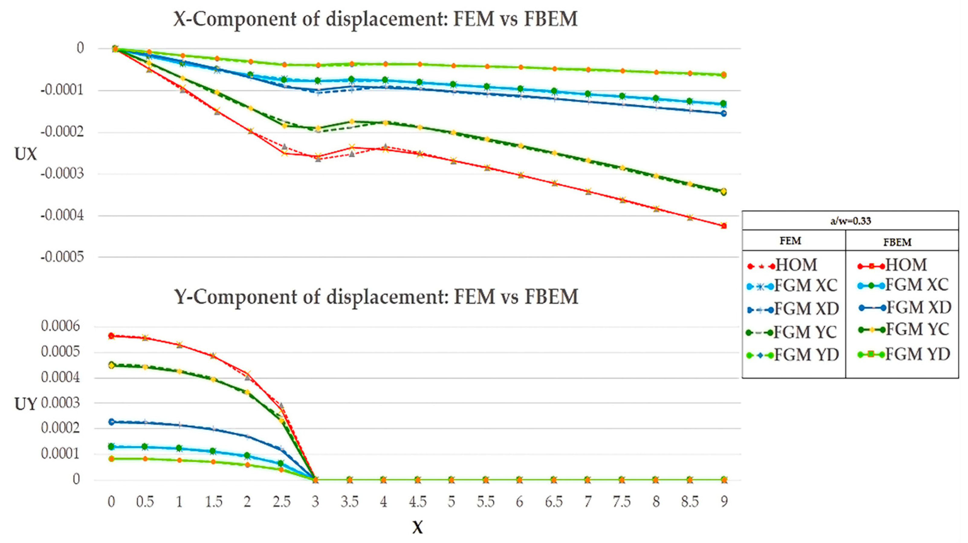
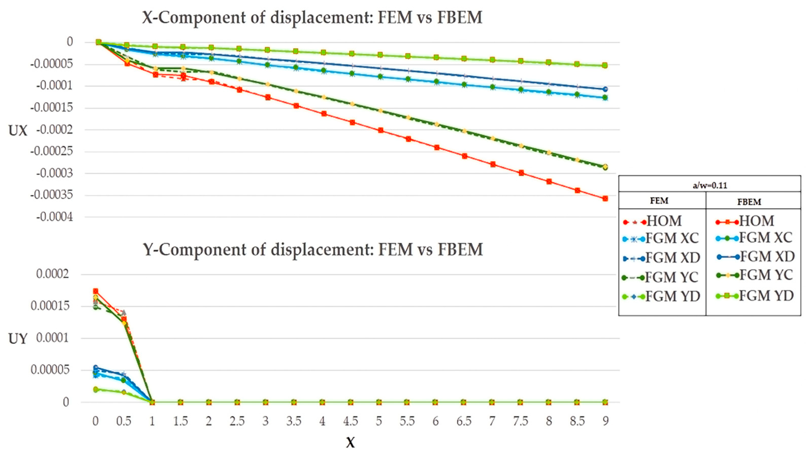
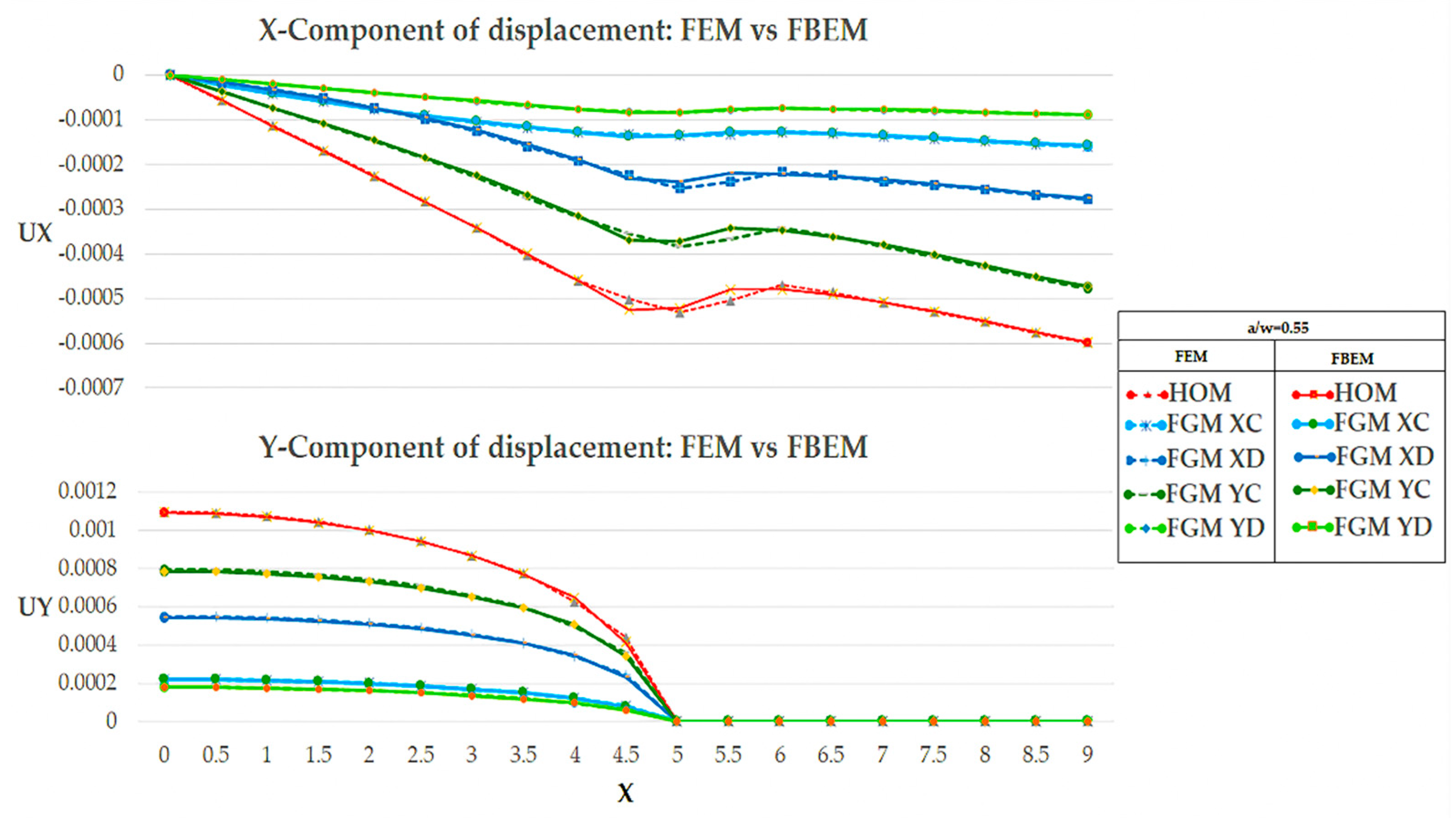
3.1. Displacement’s Comparison FEM vs. FBEM

In this section, the solution of the FBEM algorithm is discussed. The Field Boundary Element calculation was compared with a commercial FEM code result (Ansys ©). In the following Figure 4, Figure 5 and Figure 6, the displacement components along the x-direction and the y-direction are shown for the three different crack lengths together with the FBEM results. It can be seen that FBEM and FEM produced the same displacements.
In Figure 4, Figure 5 and Figure 6, the evolution of displacements along the x and y-directions as Young’s modulus of the plate varied is shown. Specifically, in Figure 4, Figure 5 and Figure 6, the crack length varied from a w = 0.11 to a w = 0.55 and the displacement along the x-direction was lower for cases where there was a variation in material properties and that was in FGM cases. In contrast, in the homogeneous cases, there was a higher displacement response since the structural response of the plate, which is closely related to material properties, did not face a smart strength along the x-direction. The y-component of the displacement was more representative of the future stress response. The y-component of displacement in each of the cases shown tended to be zero at the crack tip location as expected. The numerical evidence can be seen in the next section, where the representative SIF of stress concentration is shown.

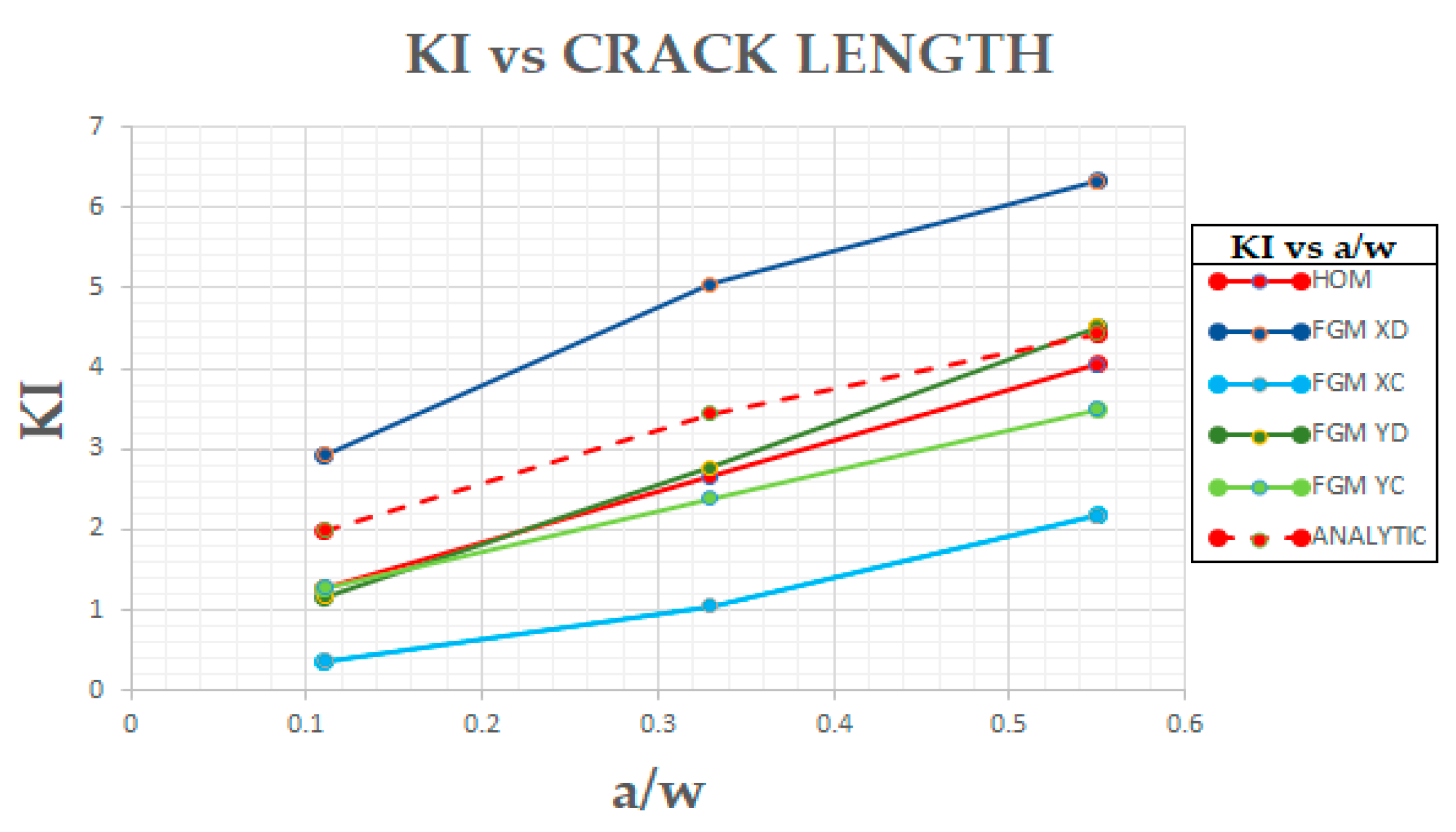
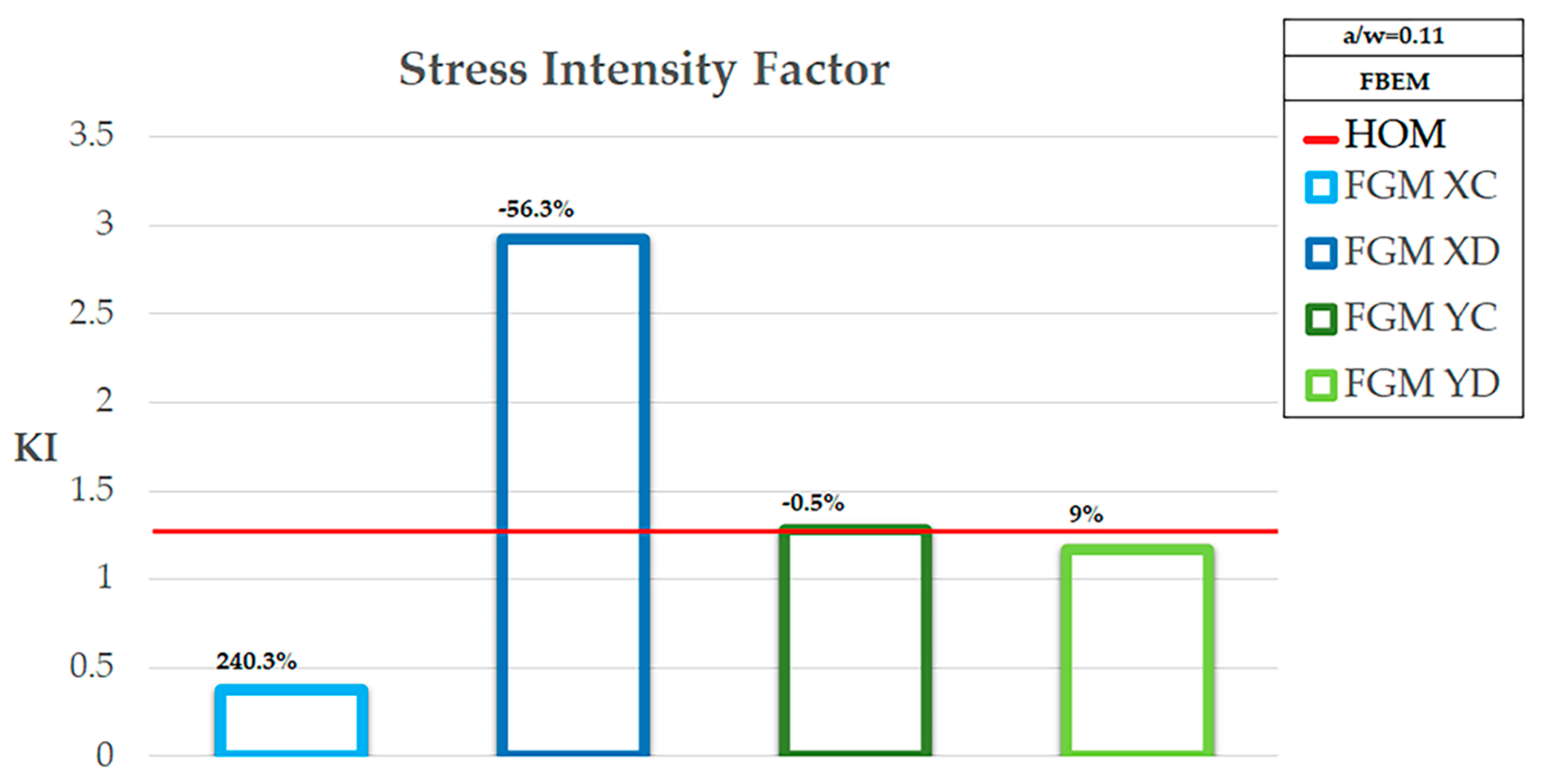
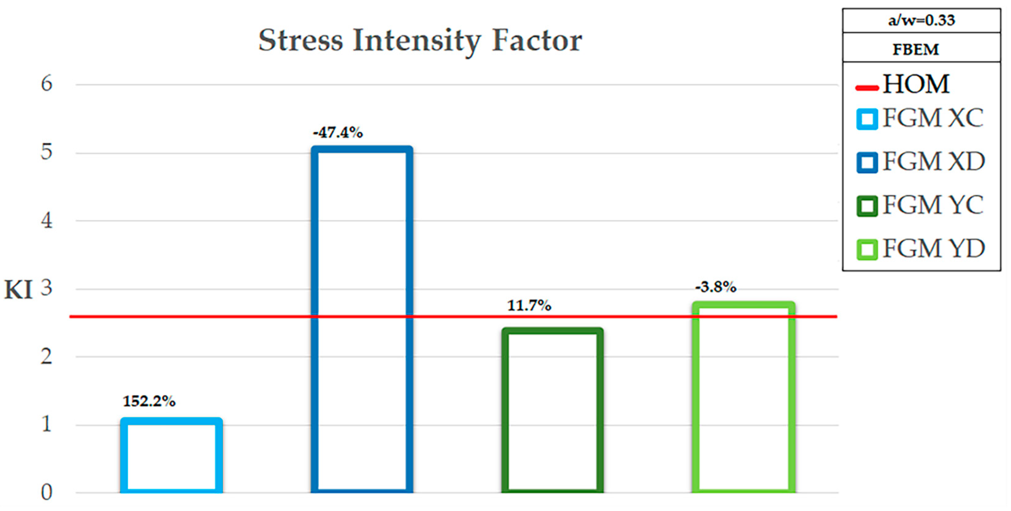
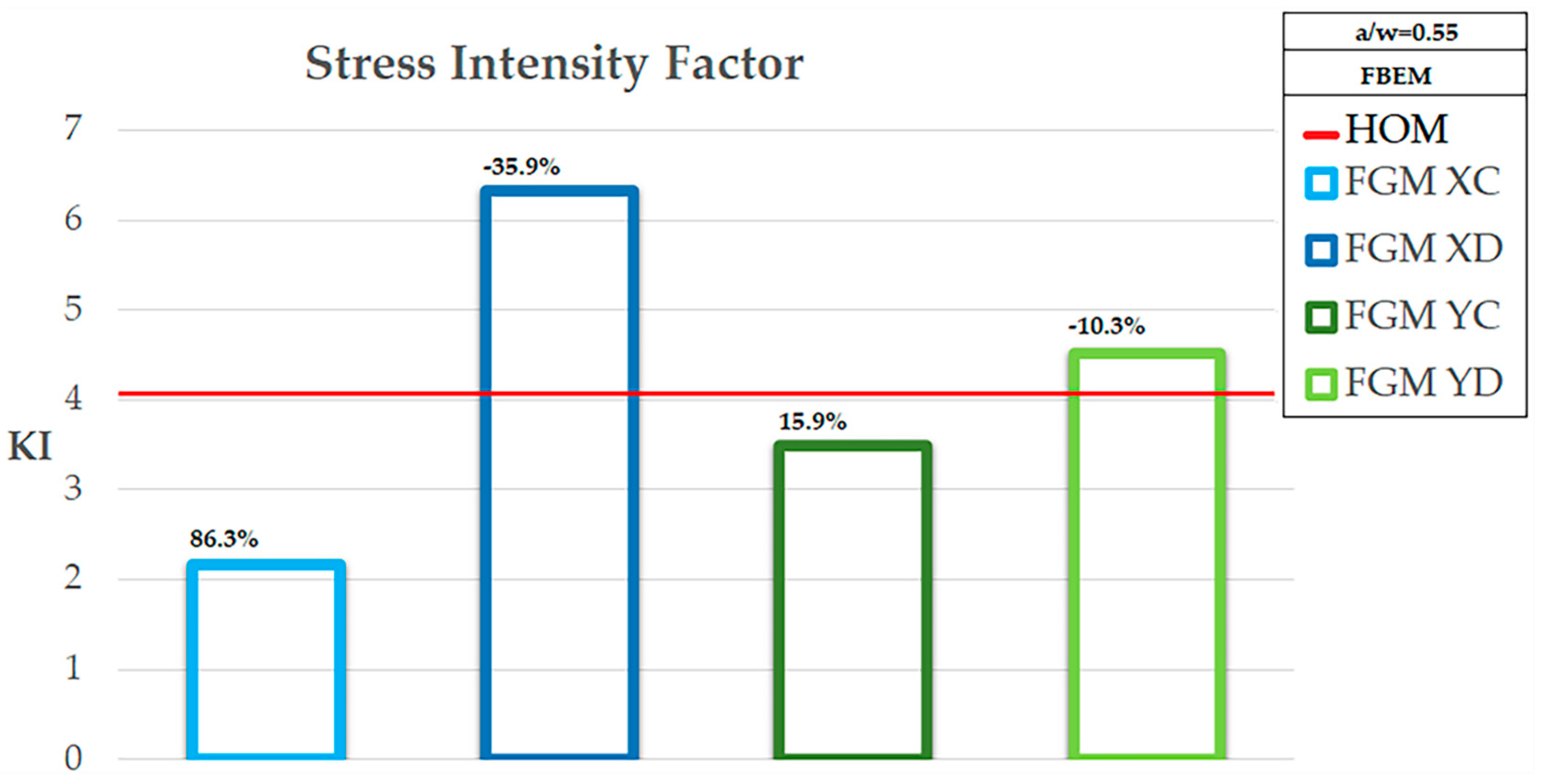
3.2. Numerical Results

To investigate the goodness of the implemented FBEM results in comparison to the analytical result [57], numerical calculations with different variations of Young’s Modulus were also performed and are reported in Figure 7 and in Table 1 regarding the KI fracture parameter only:
In particular the analytical result, shown in Table 1, was computed through the following formula:
K I = β σ π a
For completeness, summary plots of the Stress Intensity Factor KI for all Young Modulus variations and the comparison between the FBEM results for all normalized crack lengths are shown in Figure 8  ( a w = 0.11 ) , Figure 9  ( a w = 0.33 ) , and Figure 10  ( a w = 0.55 ) .
In particular, the comparison was performed using a percentage variation in Equation (16) with respect to the homogeneous case and the FBEM results reported for each case in the figures as well:
% V = K I H K I F G M K I H 100 %

4. Discussion and Conclusions

The results obtained through the FBEM formulation were first compared with standard FEM calculation obtained using the software Ansys ©. The finite element is based on constant elements hence the modulus variability has to be enforced at the element scale. No iso-parametric neither any other shape function is used to map the elasticity parameters on the element geometry allowing heterogeneity of description. A more detailed discussion about the influence of the FEM parametric description of material elasticity and its influence with respect to the FBEM approach constitutes the core of [37]. In the actual results, a comparison between standard FEM and FBEM was applied to the cracked plate where one has to expect sudden jump of stress. The effect calculated through the FBEM matched with good agreement that obtained by FEM both in terms of displacements and in terms of stresses. In the mentioned reference [37], it was shown that the influence of the mesh size rapidly decreased with the decrease in element size. In particular, it was seen to fulfill the analytical solution in the simple cases and FBEM approached the analytical solution even with rather coarse meshes. This result can be ascribed to the fact that boundary integral equations and their numerical counterpart BEM generally describe structural behavior with better approximation since the mesh concerns the boundary only.
The proposed FBEM was obtained using the homogeneous fundamental solution even with heterogeneous material, producing domain contributions. The domain contribution can be interpreted, Equation (5), as body force-like terms equal to the divergence of the stress-like tensor corresponding to the tensor variation of the elasticity with respect to the reference one applied to the fundamental solution strain, and a body force-like vector corresponding to the stress tensor of the fundamental solution applied to the gradient of the scalar variation of the elasticity. A novel boundary term arose as well due to the traction-like vector corresponding to the L i j h k ε l i j * stress.
From a numerical point of view, the domain contributes require volume discretization and internal point collocation of the equation. However, a weak integral can be resolved by numerical quadrature for this class of integrals, namely, in the 2D plane, a stress logarithmic quadrature has been used. The strong singular integrals gave rise to the displacement coefficient just as the free terms deriving from the Cauchy principal value integration did. These coefficients were calculated using the rigid body motion property of the displacement coefficient matrix.
The case study consisted of an FGM plate, in plane strain regime, axially loaded with a uniform tensile load. The plate presented a crack at the center orthogonal to the load direction. The calculation dealt with a quarter of the plate since symmetry of the structure existed. The variability of the elastic modulus was investigated with respect to the stress intensity at the crack tip. The modulus varied with an exponential low between E 0 and E 1 ; it was assumed that the modulus decreased and increased moving from the crack middle toward the plate edge both in direction of the crack length and in the direction of the applied stress, namely the x and y-directions of the assumed frame. Moreover, three crack lengths were analyzed: 0.11, 0.33, and 0.55 times the plate width, w, Equations (11)–(14).
The stress intensity factor KI is reported in Table 1. The reported results allowed a comparison between the analytical results for the homogeneous infinite plate through Equation (15).
The results obtained by the present calculation were of comparable magnitude with respect to the analytical ones. Moreover, in Table 1, the comparison of numerical SIF for different variation types of the elasticity evidenced that it was influenced by the modulus decrease or increase moving from the crack tip toward the interior of the plate. In particular, one can see that when the modulus decreased moving from the crack along the crack direction, that is perpendicular to the applied load, the SIF was greater than when the modulus increased with distance. This can be explained by the fact that a uniformly loaded plate response in terms of stress concentrated where the modulus increased. Hence, when the modulus increased toward the crack, the stress increased with a higher level than the homogeneous case. In particular, it can be seen that the KI for homogeneous plate was between the one for increasing modulus and the decreasing one.
K I X C K I H K I X D
When the variability of the material property developed along the load direction the influence of the variability on the SIF was much less evident. The SIF decreased when the modulus increased with distance and increased when the modulus decreased but it remained almost equal to the homogeneous SIF.
The variability of SIF on the crack length can be seen from the graphics in Figure 7. The figure highlights that the material variability shows that the curve representing the variability of the SIF on the crack length moved accordingly to the material stiffness at the tip.
The shift of the curve was meaningful in the cases of x-variation of the modulus and negligible when the modulus varied along the y-direction.
A final consideration suggested that the numerical calculation showed the feasibility of the method that allowed the application of integral equations to fracture mechanics even in the cases of heterogeneous materials; moreover, it was shown that the variability of the mechanical properties of the structure affected the value of the SIF. The qualitative behavior of the KI can be seen in Figure 8, Figure 9, and Figure 10 where the bars and the percentage variation (%V) of the KI were delimiting values of the homogeneous case provided the variation developed in the x-direction. Conversely, when the variation followed the y-direction, the behavior was quiet in comparison to the homogeneous one.
Finally, some remarks on the comparison between FEM and FBEM should be addressed here. A comparison was made with the standard FEM program. The finite element calculation deals with piecewise constant elastic modulus at an element scale; no variability has been accounted for within the element. The actual variability of the material properties as well as the variability of the anisotropy class at the element scale should require iso-parametric or ad hoc shape functions for the elasticity description. Such iso-parametric or hetero-parametric modelling of the material properties requires ad hoc FEM coding together with an element-wise description of anisotropy directions oriented with respect to the local axes of the element. Consequently, the FEM modelling produces more mesh dependence than FBEM due to the dependence on the mesh of the material description too; such approximation does not affect FBEM modelling [37].

Author Contributions

Conceptualization, S.P., L.E., P.F., R.Z. and V.M.; methodology, S.P., L.E., P.F., R.Z. and V.M.; software, S.P., L.E., P.F., R.Z. and V.M.; validation, S.P., L.E., P.F., R.Z. and V.M.; formal analysis, S.P., L.E., P.F., R.Z. and V.M.; investigation, S.P., L.E., P.F., R.Z. and V.M.; resources, S.P., L.E., P.F., R.Z. and V.M.; data curation, S.P., L.E., P.F., R.Z. and V.M.; writing—original draft preparation, S.P., L.E., P.F., R.Z. and V.M.; writing—review and editing, S.P., L.E., P.F., R.Z. and V.M.; visualization, S.P., L.E., P.F., R.Z. and V.M.; supervision, V.M.; project administration, V.M.; funding acquisition, V.M. All authors have read and agreed to the published version of the manuscript.

Funding

The authors acknowledge the financial grant program VALERE: “VAnviteLli pEr la RicErca”.

Institutional Review Board Statement

Not applicable.

Informed Consent Statement

Not applicable.

Data Availability Statement

Not applicable.

Conflicts of Interest

The authors declare no conflict of interest.

References

  1. Ichikawa, K. Functionally Graded Materials in the 21st Century; Kluwer Academic Publishers: Norwell, MA, USA, 2001. [Google Scholar]
  2. Watanabe, K.; Ziegler, F. Dynamics of Advanced Materials and Smart Structures. In Proceedings of the IUTAM Symposium, Dordrecht, The Netherlands, 20–24 May 2002. [Google Scholar]
  3. Pan, W.; Gong, J.; Zhang, L.; Chen, L. Functionally Graded Materials. In Proceedings of the VII Int. Symposium (FGM2002), Beijing, China, 15–18 October 2003. [Google Scholar]
  4. Irwin, G.R. Analysis of Stresses and Strains Near the End of a Crack Traversing a Plate. J. Appl. Mech. 1957, 24, 361–364. [Google Scholar] [CrossRef]
  5. Li, R.; Yang, M.; Liang, B. The Homogenized Transformation Method for the Calculation of Stress Intensity Factor in Cracked FGM Structure. Int. J. Comput. Methods 2021, 18, 2050014. [Google Scholar] [CrossRef]
  6. Minutolo, V.; Esposito, L.; Sacco, E.; Fraldi, M. Designing stress for optimizing and toughening truss-like structures. Meccanica 2020, 55, 1603–1622. [Google Scholar] [CrossRef]
  7. Wang, H.-T.; Wu, G.; Pang, Y.-Y. Theoretical and Numerical Study on Stress Intensity Factors for FRP-Strengthened Steel Plates with Double-Edged Cracks. Sensors 2018, 18, 2356. [Google Scholar] [CrossRef] [Green Version]
  8. Seifi, R. Stress intensity factors for internal surface cracks in autofrettaged functionally graded thick cylinders using weight function method. Theor. Appl. Fract. Mech. 2015, 75, 113–123. [Google Scholar] [CrossRef]
  9. Eshraghi, I.; Soltani, N. Stress intensity factor calculation for internal circumferential cracks in functionally graded cylinders using the weight function approach. Eng. Fract. Mech. 2015, 134, 1–19. [Google Scholar] [CrossRef]
  10. Chen, Y. Stress intensity factors in a finite cracked cylinder made of functionally graded materials. Int. J. Press. Vessel. Pip. 2004, 81, 941–947. [Google Scholar] [CrossRef]
  11. Mi, Y.; Aliabadi, M. Dual boundary element method for three-dimensional fracture mechanics analysis. Eng. Anal. Bound. Elements 1992, 10, 161–171. [Google Scholar] [CrossRef]
  12. Chen, T.; Wang, B.; Cen, Z.; Wu, Z. A symmetric Galerkin multi-zone boundary element method for cohesive crack growth. Eng. Fract. Mech. 1999, 63, 591–609. [Google Scholar] [CrossRef]
  13. Minutolo, V.; Ruocco, E. Boundary element modelling and optimisation of structures made of functionally graded materials. In Advances in Boundary Element Techniques; EC., Ltd.: Montreal, UK, 2005. [Google Scholar]
  14. Sutradhar, A.; Paulino, G.H. The simple boundary element method for transient heat conduction in functionally graded materials. Comput. Methods Appl. Mech. Eng. 2004, 4511–4539. [Google Scholar] [CrossRef]
  15. Chandran, K.S.R.; Imad, B. Determination of stress intensity factor solutions for cracks in finite-width functionally graded materials. Int. J. Fract. 2003, 121, 183–203. [Google Scholar] [CrossRef]
  16. Minutolo, V.; Ruocco, E. Wall structure finite-element by BEM coupling. Int. J. Mason. Res. Innov. 2019, 4, 113. [Google Scholar] [CrossRef]
  17. Fraldi, M.; Minutolo, V.; Ruocco, E. The derivation of the domain boundary integral equation governing the material nonlinearity of heterogeneous spongy structures. In Proceedings of the Third International Conference on BETEQ, Beijing, China, 10–12 September 2002. [Google Scholar]
  18. Cutolo, A.; Carotenuto, A.R.; Palumbo, S.; Esposito, L.; Minutolo, V.; Fraldi, M.; Ruocco, E. Stacking sequences in composite laminates through design optimization. Meccanica 2021, 56, 1555–1574. [Google Scholar] [CrossRef]
  19. Esposito, L.; Cutolo, A.; Barile, M.; Lecce, L.; Mensitieri, G.; Sacco, E.; Fraldi, M. Topology optimization-guided stiffening of composites realized through Automated Fiber Placement. Compos. Part B Eng. 2019, 164, 309–323. [Google Scholar] [CrossRef]
  20. Ruocco, E.; Minutolo, V. Two-dimensional stress analysis of multiregion functionally graded materials using a field boundary element model. Compos. Part B Eng. 2012, 43, 663–672. [Google Scholar] [CrossRef]
  21. Wang, B.-L.; Tian, Z.-H. Application of finite element–finite difference method to the determination of transient temperature field in functionally graded materials. Finite Elements Anal. Des. 2005, 41, 335–349. [Google Scholar] [CrossRef]
  22. Kim, J.-H.; Paulino, G.H. Finite element evaluation of mixed mode stress intensity factors in functionally graded materials. Int. J. Numer. Methods Eng. 2001, 53, 1903–1935. [Google Scholar] [CrossRef]
  23. Delale, F.; Erdogan, F. The Crack Problem for a Nonhomogeneous Plane. J. Appl. Mech. 1983, 50, 609–614. [Google Scholar] [CrossRef]
  24. Erdogan, F. The Crack Problem for Bonded Nonhomogeneous Materials Under Antiplane Shear Loading. J. Appl. Mech. 1985, 52, 823–828. [Google Scholar] [CrossRef]
  25. Erdogan, F. Fracture mechanics of functionally graded materials. Compos. Eng. 1995, 5, 753–770. [Google Scholar] [CrossRef]
  26. Eischen, J. Fracture of nonhomogeneous materials. Int. J. Fract. 1987, 34, 3–22. [Google Scholar]
  27. Konda, N.; Erdogan, F. The mixed mode crack problem in a nonhomogeneous elastic medium. Eng. Fract. Mech. 1994, 47, 533–545. [Google Scholar] [CrossRef]
  28. Gu, P.; Asaro, R. Crack deflection in functionally graded materials. Int. J. Solids Struct. 1997, 34, 3085–3098. [Google Scholar] [CrossRef]
  29. Gu, P.; Asaro, R. Cracks in functionally graded materials. Int. J. Solids Struct. 1997, 34, 1–17. [Google Scholar] [CrossRef]
  30. Anlas, G.; Santare, M.; Lambros, J. Numerical Calculation of Stress Intensity Factors in Functionally Graded Materials. Int. J. Fract. 2000, 104, 131–143. [Google Scholar] [CrossRef]
  31. Marur, P.R.; Tippur, H.V. Numerical analysis of crack-tip fields in functionally graded materials with a crack normal to the elastic gradient. Int. J. Solids Struct. 2000, 37, 5353–5370. [Google Scholar] [CrossRef]
  32. Nasirmanesh, A.; Mohammadi, S. Eigenvalue buckling analysis of cracked functionally graded cylindrical shells in the framework of the extended finite element method. Compos. Struct. 2017, 159, 548–566. [Google Scholar] [CrossRef]
  33. Ruocco, E.; Mallardo, V.; Minutolo, V.; Di Giacinto, D. Analytical solution for buckling of Mindlin plates subjected to arbitrary boundary conditions. Appl. Math. Model. 2017, 50, 497–508. [Google Scholar] [CrossRef]
  34. Ruocco, E.; Minutolo, V. Buckling Analysis of Mindlin Plates Under the Green–Lagrange Strain Hypothesis. Int. J. Struct. Stab. Dyn. 2015, 15, 1450079. [Google Scholar] [CrossRef]
  35. Dolbow, J.; Gosz, M. On the computation of mixed-mode stress intensity factors in functionally graded materials. Int. J. Solids Struct. 2002, 39, 2557–2574. [Google Scholar] [CrossRef]
  36. Zou, Z.; Wu, S.X.; Li, C. On the Multiple Isoparametric Finite Element Method and Computation of Stress Intensity Factor for Cracks in FGMs. Key Eng. Mater. 2000, 183–187, 511–516. [Google Scholar] [CrossRef]
  37. Minutolo, V.; Ruocco, E.; Ciaramella, S. Isoparametric FEM vs. BEM for elastic Functionally Graded Materials. CMES—Comput. Modeling Eng. Sci. 2009, 41, 27–48. [Google Scholar]
  38. Zhang, C.; Sládek, J.; Sládek, V. Numerical Analysis of Cracked Functionally Graded Materials. Key Eng. Mater. 2003, 251–252, 463–472. [Google Scholar] [CrossRef]
  39. Sutradhar, A.; Paulino, G.H.; Gray, L.J. On hypersingular surface integrals in the symmetric Galerkin boundary element method: Application to heat conduction in exponentially graded materials. Int. J. Numer. Methods Eng. 2004, 62, 122–157. [Google Scholar] [CrossRef]
  40. Zhang, C.; Sládek, J.; Sladek, V. Effects of material gradients on transient dynamic mode-III stress intensity factors in a FGM. Int. J. Solids Struct. 2003, 40, 5251–5270. [Google Scholar] [CrossRef]
  41. Zhang, C.; Sládek, J.; Sladek, V. Antiplane crack analysis of a functionally graded material by a BIEM. Comput. Mater. Sci. 2005, 32, 611–619. [Google Scholar] [CrossRef]
  42. Zhang, C.; Sladek, J.; Sladek, V. Transient dynamic analysis of cracked functionally graded materials. In Advances in Fracture and Damage Mechanics IV; EC Press: London, UK, 2005. [Google Scholar]
  43. Chan, Y.-S.; Paulino, G.H.; Fannjiang, A.C. The crack problem for nonhomogeneous materials under antiplane shear loading—A displacement based formulation. Int. J. Solids Struct. 2001, 38, 2989–3005. [Google Scholar] [CrossRef]
  44. Yue, Z.; Xiao, H.; Tham, L. Boundary element analysis of crack problems in functionally graded materials. Int. J. Solids Struct. 2003, 40, 3273–3291. [Google Scholar] [CrossRef]
  45. Nguyen, B.; Tran, H.; Anitescu, C.; Zhuang, X.; Rabczuk, T. An isogeometric symmetric Galerkin boundary element method for two-dimensional crack problems. Comput. Methods Appl. Mech. Eng. 2016, 306, 252–275. [Google Scholar] [CrossRef]
  46. Falini, A.; Kanduč, T. A Study on Spline Quasi-Interpolation Based Quadrature Rules for the Isogeometric Galerkin BEM; Springer Science and Business Media LLC: Berlin, Germany, 2019; pp. 99–125. [Google Scholar]
  47. Chen, L.; Wang, Z.; Peng, X.; Yang, J.; Wu, P.; Lian, H. Modeling pressurized fracture propagation with the isogeometric BEM. Géoméch. Geophys. Geo-Energy Geo-Resour. 2021, 7, 1–16. [Google Scholar] [CrossRef]
  48. Rezaiee-Pajand, M.; Emad, S.; Amir, R.M. Free vibration analysis of functionally graded hybrid matrix/fiber nanocomposite conical shells using multiscale method. Aerosp. Sci. Technol. 2020, 105, 105998. [Google Scholar] [CrossRef]
  49. Jia, B.Y.; Xin, D.; Tao, W. Behaviors of novel sandwich composite beams with normal weight concrete. Steel Compos. Struct. 2021, 38, 599–615. [Google Scholar]
  50. Rezaiee-Pajand, M.; Masoodi, A. Stability Analysis of Frame Having FG Tapered Beam–Column. Int. J. Steel Struct. 2018, 19, 446–468. [Google Scholar] [CrossRef]
  51. Sobhani, E.; Masoodi, A.R.; Ahmadi-Pari, A.R. Vibration of FG-CNT and FG-GNP Sandwich Composite Coupled Conical-Cylindrical-Conical Shell. Compos. Struct. 2021, 273, 114281. [Google Scholar] [CrossRef]
  52. Rezaiee-Pajand, M.; Masoodi, A.R.; Alepaighambar, A. Lateral-torsional buckling of functionally graded tapered I-beams considering lateral bracing. Steel Compos. Struct. 2018, 28, 403–414. [Google Scholar]
  53. Rezaiee-Pajand, M.; Masoodi, A.R. Analyzing FG shells with large deformations and finite rotations. World J. Eng. 2019, 16, 636–647. [Google Scholar] [CrossRef]
  54. Mohammad, R.-P.; Niloofar, R.-S.; Masoodi, A.R. An efficient curved beam element for thermo-mechanical nonlinear analysis of functionally graded porous beams. Structures 2020, 28, 1035–1049. [Google Scholar]
  55. Brebbia, C.; Dominguez, J. Boundary Elements. An Introductory Course; WIT: Southempton, UK, 1990. [Google Scholar]
  56. Diligenti, M.; Monegato, G. Integral evaluation in the BEM solution of (hyper)singular integral equations. 2D problems on polygonal domains. J. Comput. Appl. Math. 1997, 81, 29–57. [Google Scholar] [CrossRef]
  57. Belytschko, T.; Bathe, K.J. Computational Methods in the Mechanics of Fracture; Atluri, S., Ed.; North Holland Publishing Company: Atlanta, GA, USA, 1986; Volume 2. [Google Scholar]
Figure 1. Mesh and BCs. (i): a w = 0.11 , (ii): a w = 0.33 , (iii): a w = 0.55 .
Applsci 11 08465 g001
Figure 2. Variation of Young Modulus along the x-direction of the plate.
Applsci 11 08465 g002
Figure 3. Variation of Young Modulus along the y-direction of the plate.
Applsci 11 08465 g003
Figure 4. Comparison of the x and y-component of displacement for a w = 0.11 .
Applsci 11 08465 g004
Figure 5. Comparison of the x and y-component of displacement for a w = 0.33 .
Applsci 11 08465 g005
Figure 6. Comparison of the x and y-component of displacement for a w = 0.55 .
Applsci 11 08465 g006
Figure 7. KI vs Crack Length ( a w ).
Applsci 11 08465 g007
Figure 8. FBEM Stress Intensity Factor comparison for a w = 0.11 over the bars %V Equation (16) is reported.
Applsci 11 08465 g008
Figure 9. FBEM Stress Intensity Factor comparison for a w = 0.33 over the bars %V Equation (16) is reported.
Applsci 11 08465 g009
Figure 10. FBEM Stress Intensity Factor comparison for a w = 0.55 over the bars %V Equation (16) is reported.
Applsci 11 08465 g010
Table 1. Stress Intensity Factors’ parametric analysis.
a w [w = l] K I H A n a l y t i c a l K I H F B E M K I X D F B E M K I X C F B E M K I Y D F B E M K I Y C F B E M
0.111.985151.276752.924060.375231.170851.28338
0.333.438382.660625.055371.054792.765512.38274
0.554.438934.055226.329272.176392.260573.49758
H = Homogeneous case; XD = Decreasing Young Modulus along the x-direction; XC = Increasing Young Modulus along the x-direction; YD = Decreasing Young Modulus along the y-direction; YC = Increasing Young Modulus along the y-direction.
Publisher’s Note: MDPI stays neutral with regard to jurisdictional claims in published maps and institutional affiliations.

