Abstract
The paper aims to investigate the airflow dynamics of electric-arc spraying (EAS) with airflow pulsation. The study is focused on the dynamic structure of the airflow with an obstacle in the form of crossed electrodes at the steady and the pulsating air supply (with a frequency up to 120 Hz). The work was fulfilled using a computer simulation, the airflow “shadow” photo visualization, and the microstructure characterization of the coatings formed. It was found that when air flows along the crossed electrodes with a gap of 2 mm, a depression zone appears in the flow with a pressure drop from 0.56 MPa to 0.01 MPa. The air pulsation resulted in a change in a flow’s dynamic structure towards an increase in the length of the depression zone, which covers most of the arc, affecting the liquid metal oxidation. It is established that the frequency of a droplet formation should match the frequency of the airflow pulsation to minimize the metal oxidation. With the air pulsating at about 65 Hz, the oxide volume fraction in the aluminum coating was reduced by 3.6 times compared to the steady airflow. EAS with airflow pulsation has the potential for technological cost reduction.
1. Introduction
Surface modification and protective coating deposition are widely spread technologies used to improve the exploitation durability of machine parts and tools [1,2,3]. Electric-arc spraying (EAS) (metallization) belongs to the family of spraying technologies aimed at the formation of a coating through transferring molten metal to the target surface [4,5,6]. EAS procedure uses airflow to atomize and transfer the electrode’s material melted in a weld arc [7,8]. With that, an intense chemical interaction of the atomizing airflow with the electrode material occurs, leading to substantial burnout of alloying elements and deterioration of the deposited coating [9]. The oxidation negatively affects the microstructure leading to a decrease in exploitation behavior (wear resistance [10,11], corrosion resistance [12], pull-off strength [13], mechanical properties [14], etc.) of the coatings and bulk metal parts. The oxidizing intensity grows with an increase in air pressure and the distance between the apparatus nozzle and the processed part [15]. Therefore, the influence of an atomizing gas flow upon the quality of the deposited coatings was always in the focus of the researchers [16]. Particular attention was paid to spraying distance as a key EAS parameter, determining atomizing gas dynamics. The work [17] presents the evaluation method for the spraying distance where the molten drops retain their spherical shape before their collision with the surface. Based on the analysis of the dynamics of the drops’ flight, the maximal critical size of the spraying area was determined on the example of carbide material [17].
Much attention has been paid to the investigation of the influence of nozzle geometry and dynamics of atomizing gas flows on the properties of steel coatings [18,19,20]. Chadha et al. [21] developed the nozzles of different designs based on the simulation of the airflow geometry and atomizing velocity. By comparing these nozzles, the authors [21] revealed the presence of non-uniformity of a gas flow density and velocity depending on the type and length of the nozzle. Similar results were obtained in [22], which was devoted to investigating the process of twin-wire spraying with the application of front and axial nozzles. In [23], the flow inside and outside the spray gun and gas-particle interactions were simulated based on a three-dimensional model. The numerical hydro-dynamic analysis performed in [24,25] with the application of equations of continuity and momentums for different inclination angles of the front spraying nozzle revealed a high-velocity area inside the airflow. Experimental determination of the molten particle velocity and the porosity of the deposited coating showed that the density and the temperature of the flow grow with an increase in the electrode inclination angle.
The influence of electrodes on airflow dynamics was investigated in [24], where with the application of hydro-dynamical calculations and the help of a high-speed camera shooting, the character of wave expansion and its influence on the dimensions of the sprayed particles were studied. This work testifies the prospects of the application of pulsating and mixed flows. Zhao et al. [26] investigated the effect of impulse parameters of arc current upon the molten metal behavior and heat transfer under EAS. On the basis of the gas flow simulation using the magnet hydrodynamics equations, the authors [26] analyzed five sets of current variations, which are of interest from the point of view of the formation of the molten metal droplets. Gas dynamics of thermal spraying have been largely investigated in regard to the plasma method of atomizing. Wen et al. [27] presented the results of investigations of the arc dynamics and its influence on temperature distribution and flow fields inside and outside the heat source. This work confirmed the importance of control over airflows at different types of atomizing.
Decreasing the metal oxidation was the aim of the work [28], where the oxidizing of brass coatings with airflow at two different atomizing modes, particularly vacuum-plasma atomizing and dynamic atomizing with cold gas, was investigated. These methods are quite costly and can be used in limited cases only. In works [29,30], the importance of controlling the oxidation of a sprayed material was stressed, especially regarding the highly alloyed materials such as NiCrMoAl grade or some powder wires. When the control over oxidation is lost or the density of the coating should be increased, additional annealing is recommended, which is especially effective for Al-based materials [31,32]. Despite the effectiveness, this method is very costly and can be applied only for parts of limited sizes and coatings of certain chemical compositions.
Analysis of literary sources shows that the existing EAS technologies with air spraying flow do not eliminate oxidation of the deposited material. The proposed methods of controlling oxidation by applying neutral gases or nozzles with special designs are exceedingly costly as they increase production costs and require complicated technology and equipment. The sophisticated character of the processes at EAS requires a more thorough investigation of the atomizing flow dynamics to seek energy-efficient and resource-saving methods of controlling the oxidation of the deposited metal. At the same time, the possibility of such control using regulated pulsating airflow remains unexplored. This article is aimed at investigating the gas dynamics of the airflow in the interaction with the obstacles (the electrodes), which are characteristic of EAS. Special attention is paid to the effect of a pulsating of the airflow on the gas dynamics and metal oxidation in order to improve the quality of EAS coatings.
2. Materials and Methods
Simulation of the interaction of the atomizing gas flow with the obstacles (electrodes) was performed using ANSYS CFX simulation [33,34] based on the solutions of the Navier–Stokes equations under the following boundary conditions: airflow pressure is 0.56 MPa, temperature is 20 °C, and air density is 1.2754 kg/m3. Experimental investigation of the airflow dynamic structure was performed through “shadow” photographing described in [35]. This method allows obtaining and analyzing gas spectrograms of a gas flow within the area of electrodes’ butts (Figure 1). The head of the metallizator (3) was lighted with a point source of light (1). The image of the airflow dynamic structure was projected to the screen (7) and fixed on the photographic film (6). The investigation was carried out without the initiation of the arc; the pressure within the airflow was 0.56 MPa (air consumption was 1.5 m3/min). The images were taken using the light-green filter in two mutually perpendicular directions to obtain the “side view” and the “top view” of the electrodes.
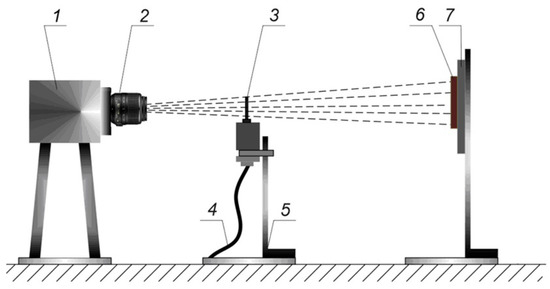
Figure 1.
Sketch of the installation for obtaining the gas spectrograms: 1—light source; 2—objective lens; 3—metallizator head; 4—compressed air supply; 5—support; 6—photographic film, 7—screen.
Regarding the periodic character of accumulation and extraction of liquid metal on electrodes’ butts, a periodic supply of atomizing air was proposed due to the surface tension forces. The aim was to provide an opportunity for the accumulation of liquid metal on the electrodes’ butts with a limitation of air influence upon the droplets. Impulse air supply was provided by means of a rotation valve-based pulsator (4) (designed by the author of this article) intended for controlled airflow interruption. The pulsator was integrated into the compressed air supply system and installed directly before the metallizator (1) (Figure 2). The pulsator valve was connected with the electric (7) motor’s shaft through the elastic coupling (6). The frequency of interrupting airflow was controlled by the rotation speed of the motor’s (7) shaft. For the pulsation frequency counting, a light diode (8) was used, providing a light beam passing through the window in the rotating disc (5) to reach the light-receiving element (9). The pulses were fixed using an oscilloscope (10).
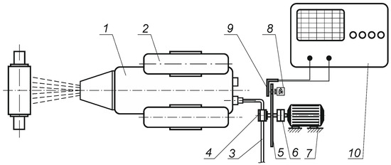
Figure 2.
The appliance for controlling pulsations of atomizing airflow: 1—electric-arc metallizator; 2—the wire holder; 3—air supply; 4—pulsator; 5—opening disc; 6—elastic coupling; 7—electric motor; 8—light source; 9—light-receiving element; 10—oscilloscope.
Electric-arc spraying was carried out using an EM-17 metallizator, equipped with the above appliance for pulsating air supply. The aluminum wire of grade ESAB OK Autrod 5356 with a 2.5 mm diameter was used as an electrode. The coatings were deposited on plates 100 × 100 × 7 mm in dimension, made of mild steel. The parameters of the EAS regime were: arc amperage—100 A, arc voltage—30 V, wire feeding—80 mm/s, an air consumption—1.5 m3/min, airflow pressure at the nozzle’s edge—0.56 MPa, the distance to the target—170 mm, and the velocity of surface spraying—6 m/min.
The coatings’ microstructure was characterized using an optical microscope Optika IM-3Met on transverse microprobes prepared by the standard metallographic procedure of polishing to a mirror surface and etching by 4 vol. % nital reagent. The images of the structure were applied to calculate the volume fraction of the oxides using the Rosival method [36]. For each EAS regime, five images of 50 m’60 mm squared were used with further averaging the results.
3. Results
With the presence of obstacles in the way of the gas flow, alternations in the character of the gas flow may happen, depending on the shape of the obstacle, characteristics of the flow, etc. It was assumed that similar phenomena occur when atomizing gas flows around the electrodes’ butts, after which altered stream characteristics could be initiated in the areas. The ANSYS CFX simulation of an electrode airflow is presented in Figure 3, showing that the zone of depression appears in the flow just behind the electrode. When analyzing the pressure distribution along the axial line, it was found that the highest-pressure value corresponds to the nozzle edge being 0.56 MPa, remaining at this level at a distance of 15 mm from the nozzle’s edge with further decreasing to 0.4 MPa. The airflow velocity there was equal to 310–350 m/s. Moving around a solid body (the electrode imitation) placed at a distance of 40 mm from the nozzle’s edge, the airflow’s pressure and velocity drastically dropped to 0.01 MPa and 30 m/sec accordingly, indicating a depression zone presence with a low oxygen concentration. In practice, the electrode metal is melted exactly within this zone, undergoing less oxidation.
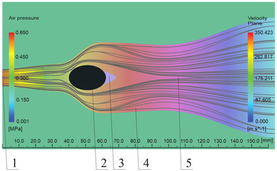
Figure 3.
The model of the airflow around a solid body (electrode) at arc metallization: 1—the section with the highest pressure on the edge of the nozzle; 2—a solid body (imitator of an electrode at arc metallization); 3—the section with the highest pressure drop (depression section); 4—airflow; 5—the section where the airflow becomes dense.
The simulated area of depression behind the electrode at EAS was further experimentally revealed by investigating the influence of two crossed electrodes upon the atomizing airflow (without arc initiating). The results of experimental fixation of the airflow are represented in Figure 4 in the form of the gas-spectrograms obtained by “shadow” photographing. As seen in the spectrograms, the presence of two electrodes crossed at an angle of 30 degrees with a gap of 2 mm leads to the formation of a depression zone at the electrode’s edges. With the aim of confining such airflow behavior, the gas spectrograms were obtained directly under electric arc spraying. The obtained images (Figure 5) show that the shape of the arc discharge at the “side view” is close to the shape of the atomizing flow when it passes the edges of electrodes (Figure 4). The light section in the central part is smaller than in the peripheral sections, possibly because of the flow’s heterogeneity and the presence of pressure drop in the center (Figure 5a). The presented gas-spectrograms allowed concluding that the arc discharge is placed within the zone of reduced pressure. It can also be seen in the “side view” that metallic molten particles that are present at the electrode’s edges form two streams, imitating the shape of the atomizing gas flow. The “top view” images of the electrodes, previously taken by other researchers, could not allow tracking the particle’s formation beyond the electrodes that happens under EAS.

Figure 4.
Gas spectrograms of the airflow passing the crossed electrodes: (a) the “top view”, (b) the “side view” (1—depression area, 2—Mach disc).

Figure 5.
The metal particles stream being atomized in the arc discharge: (a) the “top view”, (b) the “side view”.
The performed investigations showed that between the electrodes, there was an area of stable functioning of the arc discharge in which the atomized metal was subjected to lesser oxidation. The obtained results were the basis for further investigation of the perceptiveness of the atomizing air flow pulsation under the EAS process. Figure 6 presents the gas spectrograms for the case of EAS with pulsating airflow. Their analysis shows that all flow sections are in a vibrating motion relative to the flow geometrical axis. The pulsating flow has a “barrel-like” wave structure with “saw-like” pressure spreading along the flow axis. In the nozzle cross-section, a depression area appears in the shape of a centered wave. The pulsating flow behavior behind the electrode significantly varied depending on the parameters of the non-stationary flow, such as Reynolds number, Mach number, the frequency, and the relative amplitude of the flow pulsations.
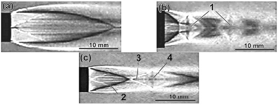
Figure 6.
Gas spectrograms of the airflows: (a) without pulsation, (b) with pulsation frequency 75 Hz for conical nozzle, (c) with pulsation frequency 75 Hz for cylindrical nozzle. 1—Mach disc; 2—the zone of the initial gas-dynamic spike; 3—the transitional zone; 4—the main zone (the front of Mach disc).
The airflow (at a standard pressure of 0.56 MPa on the nozzle edge), employing EAS for metal atomizing and transporting, usually has a supersonic velocity of about 340 m/s. The structure of such flow comprises several cyclically repeated zones with the clearly seen boundaries (Figure 6): (1) the zone of dense airflow, created due to a change in the motion of outer gas layers (the so-called Mach disc [37]); (2) the zone of the initial gas-dynamic spike (“initial” section); (3) the transitional (“second”) zone; (4) the main zone (the front part of the Mach disc). The Mach discs are formed inside the supersonic flow, the pressure of which at the edge of the nozzle is much bigger than atmospheric. Atmospheric pressure allows the gas stream to expand; it leads to a change in the direction of the external gas layers from axial to radial [37]. The alteration of a supersonic flow direction occurs on “skew” shock waves. The pressure, temperature, density, and velocity of gas vary when it passes the front of the shock wave. All these values are changed together to be described by the shockwave’s common characteristic, which is the Mach number (meaning the number of Mach discs in the flow) [37].
In gas spectrograms of the airflow without pulsation (Figure 6a), it can be seen that at a distance of up to 1 mm (at the end of the second zone), the Mach disc is absent, the zone of dense flow in the inter-electrode gap was missing. A different flow character was revealed for the pulsating airflow (Figure 6b,c). With the pulsation, a depression flow appears near the nozzle edge that ends with a shock wave (having Mach configuration). A disc-shaped wave that crosses the flow’s axis at a straight angle causes the centered depression wave. The gas flow on the nozzle’s outlet (Figure 6c) forms a centered cone-shaped area, limited by depression waves. At 75 Hz frequency (Figure 6c), all flow areas are in vibration motion. Additionally, the presence of a “barrel-like” wave structure in initial and transitional zones with “saw-like” pressure distribution along the flow’s axis is observed to be accompanied by shock waves. The zones of air flow’s break are present between the waves. The length of breaking zones increases at 75 Hz frequency, enabling a possibility of accumulating molten metal on the edges of atomized electrodes.
Analyzing the airflow and paying attention to pressure values lets us now analyze the flow characteristic. If pressure on the nozzle’s edge is not equal to atmospheric pressure, then two modes of nozzle operation are possible, namely: the mode of “under-expansion” and the mode of “over-expansion” [38]. At the “under-expansion” mode, the pressure inside the gas flow at the nozzle’s edge is bigger than the atmospheric value. As a result, the gas that leaves the nozzle is expanded in the atmosphere mixing with the environment. At that, the flow velocity outside the nozzle is not actually changed due to the formation of vortexes on the flow frontiers. In the case of “over-expansion”, the flow pressure at the nozzle’s edge is lower than atmospheric pressure [38].
Thus, it may be concluded that the structure of the atomizing flow at different pulsating frequencies will be similar to the structure of the “under-expanded” flow. It is known [37] that in “under-expanded” flow (the “nozzle’s edge pressure/atmospheric pressure” ratio exceeds 10–15), the transitional zone begins virtually right after the first “barrel” because the Mach disc covers nearly the entire flow cross-section and the mixing layers are close to each other. It is important since the airflow is slowed down near the Mach disc, creating an increased pressure zone. In this zone, the flow spreads in the form of a radial jet, making it easier to form a drop of liquid metal of the optimal size.
The oscillograms of pulsations of the atomizing flow are shown in Figure 7. It can be seen that the atomizing flow features a pulsating character with time intervals (pauses). The common feature for all pulsation frequencies is the presence of a pause in atomizing, which is needed for the formation of liquid metal on the electrodes’ butts, with their subsequent detachment from the electrodes by the airflow.

Figure 7.
The oscillograms of the atomizing airflow with the pulsation’s frequency of (a) 20 Hz, (b) 50 Hz, (c) 100 Hz.
Application of the airflow pulsation makes it possible to retain molten particles in the process of a droplet formation before its detachment, thus decreasing the influence of oxygen upon the melt. The reduction in air oxygen influence under the flow pulsation was evaluated by the aluminum coating’s microstructure analysis. As seen in Figure 8, the coatings’ microstructure had a layered pattern characteristic for EAS overlays. Figure 8a represents the microstructure of the coating obtained at steady (without pulsations) airflow. It is obvious that such a coating has as many oxide inclusions as the thick (0.5–6.0 mm) films lying between the crystallized droplets (the oxides are shown by the arrows). In contrast, the coating deposited by pulsating (67 Hz) airflow is characterized by a much lower amount of oxide films with a small number of equiaxed non-metallic inclusions distributed inside the droplets (Figure 8b). Such changes in microstructure indicate the oxidation-reduction caused by the airflow pulsation.
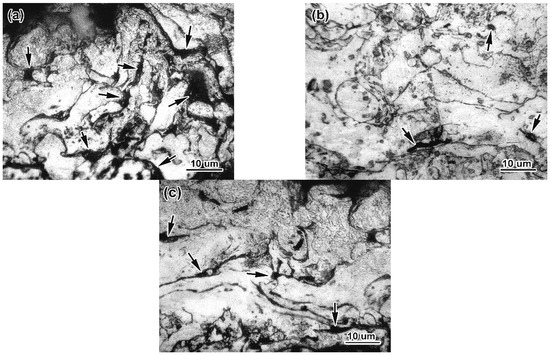
Figure 8.
The microstructure of aluminum coating, deposited (a) without airflow pulsation and with air pulsation of frequency (b) 67 Hz and (c) 120 Hz. The oxides are depicted by the arrows.
The same observations were seen for the aluminum coatings obtained with different pulsation frequencies (up to 120 Hz—Figure 8c). The results are represented by the graph of the oxide volume fraction vs. the airflow pulsation frequency illustrated in Figure 9. It can be seen that the graph had a parabolic shape with the minimum value corresponding to the frequency of about 65 Hz. With an increase in pulsation frequency up to 65 Hz, the oxide volume fraction gradually decreased to 2.6 vol. %, which is 3.6 times lower compared to the steady airflow (9.3 vol. %). When the pulsation frequency increases from 65 Hz to 120 Hz, the oxide volume fraction grows to 5.5 vol. %, remaining below the level of the steady flow. Evaluating the obtained results, one can conclude that the frequency of the optimal pulsations for aluminum coating deposition lies within 65–75 Hz interval, which provides the reduction in the metal oxidation rate.
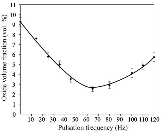
Figure 9.
The effect of the pulsating frequency of the airflow upon the oxide volume fraction in the coating deposited with aluminum wire.
4. Discussion
Presented in Figure 9, aluminum oxidation behavior under the EAS process with the airflow pulsation is explained by the action of two oppositely affecting factors. The steady oxidation-reduction at an increase in the pulsation frequency up to about 65 Hz is caused by the fact that the time interval between the air impulses is smaller than the time of accumulation of liquid metal on electrodes’ butts; thus, air is missing within the depression area. As a result, the droplets of molten metal are forming with virtually no contacting oxygen.
Starting from about 65 Hz, the pulsation frequency increase resulted in a growth in the oxidation rate, which can be ascribed to the fact that at a high pulsating frequency, the flow behavior approaches that of a steady flow. That is, the high pulsation frequency has almost no influence on the flow gas dynamics. This can be explained by the effect of the pulsation frequency on the curvature radius of molten metallic droplets forming at the electrode butt (the droplet size is important since it determines the area of liquid metal that contacts with the airflow oxygen). This approach is outlined in [39], where the mass transfer of electrode metal under the airflow pulsation was analyzed, and the conditions of the detachment of molten metal from the electrode were studied. According to [39], the curvature radius of a droplet (Rcur) can be calculated by the equation:
where vel—electrode feeding velocity, f—pulsation frequency, w—angle between the electrodes, del—diameter of the electrode.
Equation (1) was applied to evaluate the effect of the pulsation frequency under the following parameters: vel is 40–100 mm/s, w is 30 degrees, and del is 2.5 mm. The dependence of Rcur on the pulsation frequency is illustrated in Figure 10. It can be seen that with a growth in the frequency of the pulsations, the value of the curvature radius steadily increases due to a reduction in the thickness of the liquid layer. It is noteworthy that with the feeding rate increase, the curvature radius grows with less intensity, i.e., the feeding rate promotes the fine (of low radius) liquid droplet formation. This is because growth in the feeding rate is accompanied by a voltage growth leading to an increase in the mass of molten metal and thickness of the liquid layer.
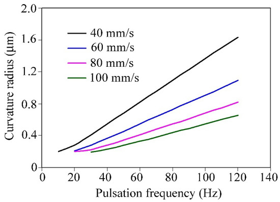
Figure 10.
Dependence of the liquid droplet curvature radius on the air flow pulsation frequency (for different electrode feeding rates).
At the optimal flow pulsation (65 Hz) frequency, the liquid metal can form a droplet of low curvature on the electrode’s butt during the pause between the air pulses; thus, the droplet is detached by each airflow pulse. At a higher frequency, there could be a case when liquid metal is not accumulated enough to form a droplet, so it is detached by some subsequent air pulse. This means that the liquid metal stays on the electrode’s butt between the air pulses being subjected to the oxidation, i.e., metal oxidation is not reduced. Thus, the frequency of a droplet formation should match the frequency of the airflow pulsation in order to minimize the metal oxidation at the electrode’s butt.
The results of gas-dynamics investigations showed that the pulsating airflow transports the molten droplets as stable as the steady flow, i.e., with straight-line particles’ movement. One can state that introducing the pulsator into standard metalizing equipment does not violate the arc burning stability at any frequency of the flow pulsation. The application of a pulsating supply of atomizing air is favorable for resource saving since the air pulsation allows the metal oxidation to decrease, thus decreasing the loss of alloying elements, which burn out in atomizing airflow. Accordingly, the content of alloying elements in the electrode can be corrected (reduced), leading to lower production costs. The air consumption can also be dropped significantly, meaning a reduction in energy expenses needed for the air supply.
The application of EAS with airflow pulsation will potentially ensure obtaining the coatings with improved exploitation durability. Within this context, the investigation of the chemical composition of oxide inclusions, as well as tribological and corrosion behaviors of the coatings deposited with airflow pulsation, should be studied in further extended research.
5. Conclusions
The characteristics of the gas dynamics of the airflow under the electric-arc spraying with airflow pulsations and its effect on aluminum coating oxidation behavior were evaluated. The following conclusions can be drawn:
- When the air flows around the obstacle (two crossed electrodes), a depression zone appears within the flow behind the obstacle, in which favorable conditions for the formation of the metal droplets are reached.
- It was revealed that the airflow pulsation caused the change in the flow structure. Particularly, the length of the zone with reduced pressure increased, covering most of the electric arc area. Between the airflow pulses, the electrode material was melted, being in the low-pressure zone with minimal contact with oxygen, reducing molten metal oxidation. It is stated that the frequency of the airflow pulsation should match the frequency of a single metal droplet formation/detachment in order to minimize the metal oxidation.
- With the airflow pulsation frequency rising to 65 Hz, the volume fraction of the oxide inclusions gradually decreased by 3.6 times compared to the steady airflow. With a further frequency increase to 120 Hz, the content of oxides increased, remaining still lower than that of the steady airflow. It was found that at a high frequency (more than 120 Hz), the air pulsation has almost no influence on the dynamics of an atomizing airflow and the metal oxidation.
Author Contributions
Conceptualization, I.Z., V.R. and V.C.; writing—original draft preparation, I.Z. and V.R.; writing—review and editing, I.Z., V.R. and V.C.; methodology, V.R. and V.C.; investigation, I.Z.; validation, I.Z.; supervision, V.C. All authors have read and agreed to the published version of the manuscript.
Funding
This research received no external funding.
Institutional Review Board Statement
Not applicable.
Informed Consent Statement
Not applicable.
Data Availability Statement
Data sharing is not applicable to this article.
Conflicts of Interest
The authors declare no conflict of interest.
References
- Mordyuk, B.N.; Voloshko, S.M.; Zakiev, V.I.; Burmak, A.P.; Mohylko, V.V. Enhanced resistance of Ti6Al4V alloy to high-temperature oxidation and corrosion by forming alumina composite coating. J. Mater. Eng. Perform. 2021, 30, 1780–1795. [Google Scholar] [CrossRef]
- Efremenko, V.G.; Chabak, Y.G.; Shimizu, K.; Lekatou, A.G.; Zurnadzhy, V.I.; Karantzalis, A.E.; Halfa, H.; Mazur, V.A.; Efremenko, B.V. Structure refinement of high-Cr cast iron by plasma surface melting and post-heat treatment. Mater. Des. 2017, 126, 278–290. [Google Scholar] [CrossRef]
- Chabak, Y.G.; Fedun, V.I.; Pastukhova, T.V.; Zurnadzhy, V.I.; Berezhnyy, S.P.; Efremenko, V.G. Modification of steel surface by pulsed plasma heating. Prob. At. Sci. Technol. 2017, 110, 97–102. [Google Scholar]
- Korobov, Y.; Filippov, M.; Makarov, A.; Malygina, I.; Soboleva, N.; Fantozzi, D.; Andrea, M.; Koivuluoto, H.; Vuoristo, P. Arc-sprayed Fe-based coatings from cored wires for wear and corrosion protection in power engineering. Coatings 2018, 8, 71. [Google Scholar] [CrossRef]
- Darut, G.; Dieu, S.; Schnuriger, B.; Vignes, A.; Morgeneyer, M.; Lezzier, F.; Devestel, F.; Vion, A.; Berguery, C.; Roquette, J.; et al. State of the art of particle emissions in thermal spraying and other high energy processes based on metal powders. J. Clean. Prod. 2021, 303, 126952. [Google Scholar] [CrossRef]
- Gedzevicius, I.; Valiulis, A.V. Analysis of wire arc spraying process variables on coatings properties. J. Mater. Process. Technol. 2006, 175, 206–211. [Google Scholar] [CrossRef]
- Abd Malek, M.H.; Saad, N.H.; Abas, S.K.; Roselina, N.N.; Shah, N.M. Performance and microstructure analysis of 99.5% aluminium coating by thermal arc spray technique. Procedia Eng. 2013, 68, 558–565. [Google Scholar] [CrossRef]
- Gustke, K.; Gebauer, J.; Drehmann, R.; Lasagni, A.F.; Lampke, T. Enhancement of the Adhesion of Wire Arc Sprayed Coatings on Carbon Fiber-Reinforced Plastic by Surface Laser Structuring. Coatings 2021, 11, 467. [Google Scholar] [CrossRef]
- Borisova, M.Z.; Struchkov, N.F.; Vinkurov, G.G. Evaluation of the content of corundum in the wear-resistant coating applied by wire arc metallization of a powder wire with fireproof additives. Procedia Struct. Integr. 2019, 20, 48–52. [Google Scholar] [CrossRef]
- Zhang, Y.; Shimizu, K.; Yaer, X.; Kusumoto, K.; Efremenko, V.G. Erosive wear performance of heat treated multi-component cast iron containing Cr, V, Mn and Ni eroded by alumina spheres at elevated temperatures. Wear 2017, 390–391, 135–145. [Google Scholar] [CrossRef]
- Efremenko, V.G.; Chabak, Y.G.; Lekatou, A.; Karantzalis, A.E.; Efremenko, A.V. High-temperature oxidation and decarburization of 14.55 wt pct Cr-cast Iron in dry air atmosphere. Metall. Mater. Trans. A 2016, 47, 1529–1543. [Google Scholar] [CrossRef]
- Sukhova, O.V.; Polons’kyi, V.A.; Ustinova, K.V. Corrosion resistance of alloys of the Al–Cu–Fe–(Si, B) system in mineralized saline and acid solutions. Mater. Sci. 2019, 55, 285–292. [Google Scholar] [CrossRef]
- Zakharova, I.V. Determination of adhesion of the coating deposited by arc spraying with pulsation of atomizing air flow. Eur. J. Enterp. Technol. 2021, 3, 39–47. [Google Scholar] [CrossRef]
- Rykavets, Z.M.; Bouquerel, J.; Vogt, J.-B.; Duriagina, Z.A.; Kulyk, V.V.; Tepla, T.L.; Bohun, L.I.; Kovbasyuk, T.M. Investigation of the microstructure and properties of TRIP 800 steel subjected to low-cycle fatigue. Prog. Phys. Met. 2019, 20, 620–633. [Google Scholar] [CrossRef]
- Newbery, A.P.; Grant, P.S. Oxidation during electric arc spray forming of steel. J. Mater. Process. Technol. 2006, 178, 259–269. [Google Scholar] [CrossRef]
- Bitharas, I.; McPherson, N.A.; McGhie, W.; Roy, D.; Moore, A.J. Visualisation and optimisation of shielding gas coverage during gas metal arc welding. J. Mater. Process. Technol. 2018, 255, 451–462. [Google Scholar] [CrossRef]
- Zverovshchikov, A.; Tarantsev, K.; Borisov, D. Determination of the parameters of the spray area during electric arc dispersion of the material. Mater. Today Proc. 2021, 38, 1452–1453. [Google Scholar] [CrossRef]
- Chen, Y.; Liang, X.; Liu, Y.; Xu, B. Numerical analysis of the effect of arc spray gun configuration parameters on the external gas flow. J. Mater. Process. Technol. 2009, 209, 5924–5931. [Google Scholar] [CrossRef]
- Toma, S.L.; Bejinariu, C.; Baciu, R.; Radu, S. The effect of frontal nozzle geometry and gas pressure on the steel coating properties obtained by wire arc spraying. Surf. Coat. Technol. 2013, 220, 266–270. [Google Scholar] [CrossRef]
- Mohan, B.; Yang, W.; Yu, W. Effect of internal nozzle flow and thermo-physical properties on spray characteristics of methyl esters. Appl. Energy 2014, 129, 123–134. [Google Scholar] [CrossRef]
- Chadha, S.; Jefferson-Loveday, R.; Hussain, T. Effect of nozzle geometry on the gas dynamics and evaporation rates of Suspension High Velocity Oxy Fuel (SHVOF) thermal spray: A numerical investigation. Surf. Coat. Technol. 2019, 371, 78–89. [Google Scholar] [CrossRef]
- Liao, H.L.; Zhu, Y.L.; Bolot, R.; Coddet, C.; Ma, S.N. Size distribution of particles from individual wires and the effects of nozzle geometry in twin wire arc spraying. Surf. Coat. Technol. 2005, 200, 2123–2130. [Google Scholar] [CrossRef]
- Bolot, R.; Planche, M.-P.; Liao, H.; Coddet, C. A three-dimensional model of the wire-arc spray process and its experimental validation. J. Mater. Process. Technol. 2008, 200, 94–105. [Google Scholar] [CrossRef]
- Ryoji, T.; Masashi, Y. Effect of plate mounted between two wires in electric arc spraying. J. Comput. Sci. 2019, 32, 56–67. [Google Scholar] [CrossRef]
- Shinde, S.V.; Gildersleeve, E.J.V.; Johnson, C.A.; Sanjay, S. Segmentation crack formation dynamics during air plasma spraying of zirconia. Acta Mater. 2020, 183, 196–206. [Google Scholar] [CrossRef]
- Zhao, Y.; Lee, P.S.; Chung, H. Effect of pulsing parameters on drop transfer dynamics and heat transfer behavior in pulsed gas metal arc welding. Int. J. Heat Mass Transf. 2019, 129, 1110–1122. [Google Scholar] [CrossRef]
- Wen, K.; Liu, X.; Zhou, K.; Liu, M.; Zhu, H. 3D time-dependent numerical simulation for atmospheric plasma spraying. Surf. Coat. Technol. 2019, 371, 344–354. [Google Scholar] [CrossRef]
- Huang, C.J.; Yang, K.; Li, N.; Li, W.Y.; Planche, M.P.; Verdy, C.; Liao, H.L.; Montavon, G. Microstructures and wear-corrosion performance of vacuum plasma sprayed and cold gas dynamic sprayed Muntz alloy coatings. Surf. Coat. Technol. 2019, 371, 172–184. [Google Scholar] [CrossRef]
- Daram, P.; Munroe, P.R.; Banjongprasert, C. Microstructural evolution and nanoindentation of NiCrMoAl alloy coating deposited by arc spraying. Surf. Coat. Technol. 2020, 391, 125565. [Google Scholar] [CrossRef]
- Azarmi, F.; Sevostianov, I. Comparative micromechanical analysis of alloy 625 coatings deposited by air plasma spraying, wire arc spraying, and cold spraying technologies. Mech. Mater. 2020, 144, 103345. [Google Scholar] [CrossRef]
- Zhou, J.; Yang, M.; Wang, R.; Xuming, P. Annealing behavior of aluminum coating prepared by arc spraying on P355NL1 steel. Surf. Coat. Technol. 2017, 330, 53–60. [Google Scholar] [CrossRef]
- Ly, C.Q.; Le, Q.T.; Van Nguyen, T.; Phung, H.T.T. Heat Treatment of Thermal Spray Duplex Coating System of Aluminum-Nickel Chromium Alloy on Carbon Steel. J. Therm. Spray Technol. 2013, 22, 1383–1387. [Google Scholar] [CrossRef]
- Ejeh, C.; Afgan, I.; Shittu, R.; Sakirudeen, A.; Anumah, P. Investigating the impact of velocity fluctuations and compressibility to aerodynamic efficiency of a fixed-wing aircraft. Results Phys. 2020, 18, 103263. [Google Scholar] [CrossRef]
- Papukchiev, A.; Buchholz, S. Validation of ANSYS CFX for gas and liquid metal flows with conjugate heat transfer within the European project THINS. Nucl. Eng. Des. 2017, 312, 338–350. [Google Scholar] [CrossRef]
- Royanov, V.; Zakharova, I.; Lavrova, E. Development of properties of spray flow and nature of pressure distribution in electric arc metallization. East. Eur. J. Enterp. Technol. 2017, 5, 41–49. [Google Scholar] [CrossRef][Green Version]
- Efremenko, V.; Pastukhova, T.; Chabak, Y.; Efremenko, A.; Shimizu, K.; Kusumoto, K.; Brykov, M. Three-body abrasive wear behaviour of metastable spheroidal carbide cast irons with different chromium contents. Int. J. Mater. Res. 2018, 109, 147–156. [Google Scholar] [CrossRef]
- Norifumi, O.; Masami, Y.; Kazuo, K. Detection of shock structure around Mach disk in axisymmetric plasma jet. Vacuum 2014, 110, 149–153. [Google Scholar] [CrossRef]
- Xinmeng, T.; Makoto, A.; Hayashi, A.K.; Nobuyuki, T. Numerical investigation of a high pressure hydrogen jet of 82 MPa with adaptive mesh refinement: The starting transient evolution and Mach disk stabilization. Int. J. Hydrog. Energy 2017, 42, 7120–7134. [Google Scholar] [CrossRef]
- Royanov, V.; Zakharova, I.; Kriuchkov, M.; Chigarev, V. Investigation of factors, determining dispersity of coating particulates arc sputtering with pulsating spraying stream. World Sci. 2020, 1, 10–20. [Google Scholar] [CrossRef]
Publisher’s Note: MDPI stays neutral with regard to jurisdictional claims in published maps and institutional affiliations. |
© 2021 by the authors. Licensee MDPI, Basel, Switzerland. This article is an open access article distributed under the terms and conditions of the Creative Commons Attribution (CC BY) license (https://creativecommons.org/licenses/by/4.0/).