
Scaling of Rain Attenuation Models: A Survey


Abstract
:1. Introduction
- We developed a scaling rain attenuation technique taxonomy and then organized all the relevant literature according to the taxonomy;
- In this work, we developed a comparative study of the existing scaling techniques and a comparative study of these methods.
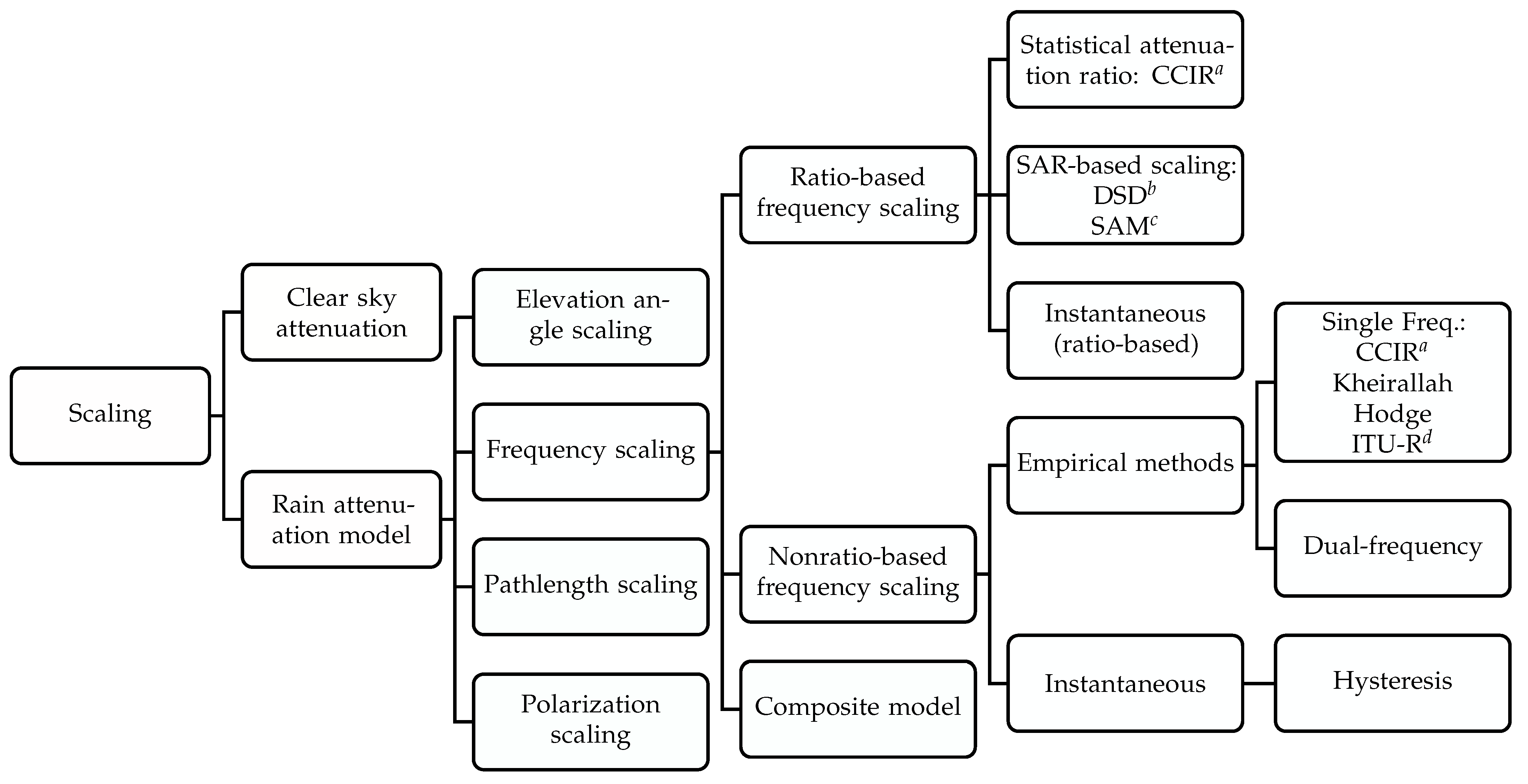
2. Taxonomy
3. Existing Scaling Techniques
3.1. The Clear-Sky-Based Scaling
| Algorithm 1: Clear sky frequency scaling [21]. |
| Data: Radiosounding data Temperature in , pressure in , and |
| relative humidity in % at different layer heights in m. |
| // Due to gas, fog, and cloud |
| 1 Compute specific gas attenuation /* Equation (4) */ |
| 2 Compute liquid water content by the [19] method |
| 3 Compute cloud attenuation by the ITU-R [20] |
| 4 Compute gas attenuation for a layer |
| 5 Compute cloud attenuation for a layer |
| 6 Compute total attenuation /* Equation (3) */ |
| // In nonrainy conditions |
| 7 Compute /* Equation (3) */ |
| 8 Compute frequency-scaled attenuation /* Equation (6) */ |
3.2. Elevation Angle Scaling
- I.
- Power-law based technique:Elevation angle scaling is defined as the ratio of rain attenuation at the zenith and the slant paths ( from to ) in [11]. The following simple formulation presents a competent model as the scaling factor :
- II.
- Cosecant-rule-based technique [11]:The scaling factor () is defined as the proportion of the attenuation across and the one anticipated from the zenith path using the simple cosecant law:The scaling factor can be calculated as the approximated fourth-order polynomial as:where , and are the coefficients of (10);
- III.
- Time-series-based technique:There is a strong impact of the elevation angle on the design of telecommunication facilities, particularly the low Earth orbit (LEO) satellites. At a low elevation angle for the LEO satellite, if a single rain cell intercepts the propagated signal from the Earth station antenna, it is possible to scale the elevation angle with the rainy time series generation technique [24] as per (11).where the subscripts “1” and “2” are used for the base (reference) measured and operating (target) datasets. Here, the rain height and the antenna height are, respectively, and , and both are with reference to the sea level, is the elevation angle, and f is the frequency in GHz. However, if multiple rain cells exist, it is impossible to scale the attenuation, and (11) will not be valid. It is assumed that by picking a collection of episodes from the ITALSAT database and scaling it to the factor indicated in (11), it is possible to recreate rain reduction statistics at a different frequency, height, and elevation for any other location. This technique needs several data processing steps, and among these steps, the most important things to check are: the original elevation angle needs to be mapped (e.g., from to ); 20 terms are then expanded to result in a database to investigate whether there exist multiple rain cells (as in the case of multiple rain cells, the assumption made by (11) will not be valid). In [25], the effect of rain attenuation on the elevation angle was assessed using the synthetic storm approach to create rain attenuation time series. The study showed that if the elevation angle decreases to , the impact of rain attenuation increases significantly, and at higher elevation angles (i.e., to ), the influence of rain attenuation is negligible. Such results are closely related to the value of the effective pathlength. These preliminary results suggest that using a prediction model for low elevation angle application systems such as the LEO satellite should consider the significant impact of rain attenuation, particularly in the heavy rain region.
3.3. Frequency Scaling
3.3.1. Frequency-Ratio-Based Scaling
- I.
- SAR-based method:Instead, in real-time applications, the frequency scaling principle has been proposed to provide static scaling attenuation. Most of the statistical scaling methods consider only frequency as the parameter. The SAR method considers the percent of time exceeded with a rain rate. The statistical attenuation due to clear air is required to be calculated similar to (1). A significant disadvantage of such a model is that these apply only to the same pair of frequencies, for which the related coefficients are determined through the investigated datasets. Electromagnetic propagation becomes disturbed by many environmental factors such as gases, raindrops, water vapor, and similar factors. Many researchers tried to establish empirical relationships of a satellite link for two channels by approximating the ratio (, is used to mean ) for different GHz frequency bands. The most straightforward approach to present the SAR through mathematical means is [28]:The SAR-based method implementation was proposed in [12] as:where and are the attenuations in at frequencies () and (), respectively;
- II.
- SAR from models:These categorized models do not include an explicit dependence on frequency, but stem from attenuation models. These attenuation models yield attenuation values that can form a ratio to predict SAR for a given pair of frequencies.where SACA is the statistical attenuation in reference to clear air; p is the percent of time exceedance of the occurring rain event for a considered pair of frequencies and ;
- (a)
- DSD-based path-averaged rain rate:The rain attenuation is significantly influenced by the distribution of the raindrop size rather than the rain rate. The size of raindrops varies in a single rain event. Therefore, the chance of scattering, refraction, or absorption varies greatly. For this reason, the analytical raindrop-based attenuation technique has good accuracy compared to the rain-rate-based model. The specific attenuation is calculated from the rain rate, and the raindrop size impacts the specific attenuation [29]. Different types of statistical and physical raindrop size distribution models were presented in [30,31]. Based on the experimental measurements, an exponential distribution was used to represent the DSD in [32]:where is a constant proposed in [33] and is a coefficient parameter in millimeters depending on the rainfall rate ( where R is the rainfall rate measured in ). The DSD can also be used to calculate a path-averaged rain rate; is a function of distance in the horizontal direction; z is related to ; is the raindrop falling velocity; the diameter of the raindrop is D as in [34]. The path-averaged rain rate can be defined as:The DSD-derived attenuation values can be used to produce a ratio, yielding a model, as follows:The problem with this approach of frequency scaling is that it needs a sophisticated device to record the drop size, and most rain attenuation-related datasets do not include the DSD-based information;
- (b)
- DSD-based specific attenuation ratio:The specific attenuation () is given by the following integral equation [35]:where is the total cross-section for a spherical raindrop, is the number density of raindrops with an equivalent radius in the interval , represents raindrop size distribution, and is the maximum mean raindrop radius. The integral equation can be changed to summation for numerical calculation as in [36,37]:where is the incremental radius, P is the integer number of , and is the wavelength corresponding to the frequency f. The specific attenuation factor can be defined for the frequency (GHz) and (GHz) as and , respectively. Now, the ratio of these two specific attenuations can be calculated as:where the notation is constant. Thus, the constant and the specific attenuation of a baseline link can be used to estimate a target links’ attenuation. There is a popular application of the specific attenuation to predict the attenuation of a satellites’ downlink channel using the specific attenuation of the uplink channel;
- (c)
- The use of the spatial rain rate profile [38]:A real-time method for frequency scaling that was demonstrated in [13] has addressed the spatial rain distribution by adopting the exponential rain cell distribution known as the SAM, as in [38]. The fundamental concept is to provide the geographical rain rate profile for the rainfall rates, where the rain rate can be recorded. The SAM considers the rainfall rate’s spatial profile as exponential and varies as:where is the rain rate at a range of h (the projection of the slant link up to the rainy region) from the receiver at any time and is the point rain rate at the receiver located at the corresponding time. Frequency scaling has to do with the variation of the propagation effects as a function of frequency. The concept of frequency scaling was proposed to yield the scaling attenuation statics instead of real-time applications;
- III.
- Instantaneous (ratio-based):The instantaneous scaling technique is defined as the ratio of clear air attenuation at a high and low frequency, respectively. In the experiment [6], additional parameter time was considered representing the sample timings in (1). Usually, the rain attenuation value given by (1) is noisy, so a moving average filter is used to smooth the samples where the window duration is 30 s [6]. However, a larger window duration of 60 s was reported in [39]. However, the downside of the proposed method is that the applicable frequency range is short in the range of 20–30 GHz, where the scaling method is given by:where denotes the specific attenuation coefficient whose value can be determined with the help of the nonlinear least squares approach. The unique feature of this model is that it is a good candidate for real-time applications based on spatial variation through the specific attenuation index. The main challenge in frequency scaling is the nonuniform rain rate distribution and the nonuniformity of the DSD of the rain along its path. The distribution of the frequency scaling factors in the K and Q bands was examined with the rain rate, and the DSD measurement results in [14]. However, it was not easy to compare these two results due to the unavailability of the rain rate distribution and the DSD of the rain information along the entire path. To determine the short-term scaling, moving and block average and sampling techniques were used, and it was recommended to limit this instantaneous time within 5 min [40].
3.3.2. Nonratio-Based Frequency Scaling
- I.
- Empirical formula-based scaling method:The link between the upper and base frequency attenuation cannot be represented in a precise ratio form in a nonratio model. Nonratio models do not predict SAR, but quantify the relationship between and through empirical relationships;
- (a)
- Single frequency:The frequency scaling ratio can be implemented on the level of the attenuation of the primary frequency as explained in [41]. The primary frequency-level-based attenuation can be defined as [42]:where k and are constants that depend on the frequency and drop size distribution and , are the attenuations corresponding to the frequencies (GHz) and (GHz). In (24), the considered pathlength was developed at about 4 km, and this scaling formula can be used at the frequency of 60 GHz. The drawback of this technique is that it needs the coefficients k and derived through the frequency and the DSD. This procedure was simplified in [27], and through the empirical formula, ITU-R (25) can be adopted. The polynomial-based frequency scaling technique was proposed in [43,44];
- i.
- ITU-R model:ITU-R has adopted a model to predict frequency scaling as [45]:where the values of and are given by:The applicable frequency of this model [45] is limited to 7–55 GHz;
- ii.
- Use of the specific attenuation relation:Using the power-law-based specific attenuation relationship, we can write:where is the percentage of time exceedance, A is the attenuation, R is the point rain rate with percentage of time exceedance and l is the corresponding effective path length.The scaling relationship assumes that both frequencies are coincidental (that is, seen along the same path, i.e., we presume that R and l are the same).
- iii.
- Rain rate depending on a Gaussian distribution:In [46], it was assumed that the point rain rate along the propagation path could be expressed as a Gaussian function of position. Therefore, the instantaneous attenuation can be formulated as:is the peak rain rate along the path L. The distance is measured from the position of maximum rain rate intensity, and is a measure of the cellular rain structure. Under these conditions, the attenuation ratio for frequencies and was given by [46] as follows:where , and are parameters associated with frequencies and , respectively. This method does not establish a strict ratio relationship because is a function of ;
- (b)
- Dual-frequency:Two frequency scaling models can usually be either linear or nonlinear. The ratio of attenuation at two frequencies is used in the majority of the two frequency models. Considering the same case as for linear-equation-based estimation, the estimated attenuation is formed in a different way as in [47]:where and are the parameters related to the frequencies , and it was assumed that the pathlengths in the considered links could be approximated to be the same in a condition where the Earth antennas’ station elevation angle was the same for synchronized satellite links;
- II.
- Instantaneous:The instantaneous rain attenuation is performed using the spatial rain rate distribution developed through the SAM rain rate distribution. The hysteresis attenuation behavior is noticed between different frequency bands, especially the downlink and uplink operating frequency of the satellite microwave link from the Earth station facility. The rain attenuation at two frequencies shows a hysteresis behavior, which was revealed in [41,48]. Moreover, the impact of the hysteresis for less severe episodes was not seen (such as widespread stratiform rain where the peak attenuation is not exceeded). In [49], it was noticed that the isopleths of the attenuation of a pair of frequencies tend to follow medium-to-high attenuation levels, such that the attenuation process can be viewed as jointly log-normal (a log-normal model to describe the statistical behavior of rain attenuation). Consequently, the mean, standard deviation, and covariance parameters of the two frequencies were determined using the cumulative distribution function of the rain attenuation graph (Gauss integral/log). The resulted covariance parameter indicates the correlation of the frequencies. The authors recommended a modified statistical parameter “standard deviation” to control uplink power through a modification as:where is a log-normal variable with zero mean () and standard deviation (STD) ; is the STD of a links’ attenuation depending on any other radio links. The STD for the independent case be written as . These two STD can be related to the reduction coefficient () as [50]:where we can compute for the pair of frequencies for which we know and vice versa. This model supports frequency ranges up to 1–100 GHz [49]. It also relies on rain inhomogeneity and considers the significant association between the peak precipitation and attenuation values. At a lower base frequency, the attenuation levels are close to that of the CCIR relation of (13).
3.3.3. Composite Frequency Scaling Model
3.4. Pathlength Scaling
3.5. Polarization Scaling
4. Comparison of Scaling Models
5. Research Scopes and Challenges
5.1. Experiment Planning
5.2. Synthetic Storm Approach-Based Elevation Angle Scaling
5.3. Application of Artificial Neural Network (AI) for Radio Link Scaling
5.4. Enhancement of Composite Scaling Technique
6. Conclusions
Author Contributions
Funding
Institutional Review Board Statement
Informed Consent Statement
Data Availability Statement
Conflicts of Interest
References
- Samad, M.A.; Diba, F.D.; Choi, D.Y. A Survey of Rain Fade Models for Earth–Space Telecommunication Links—Taxonomy, Methods, and Comparative Study. Remote Sens. 2021, 13, 1965. [Google Scholar] [CrossRef]
- Samad, M.A.; Diba, F.D.; Choi, D.Y. A Survey of Rain Attenuation Prediction Models for Terrestrial Links—Current Research Challenges and State-of-the-Art. Sensors 2021, 21, 1207. [Google Scholar] [CrossRef] [PubMed]
- Lu, Q.; Zhang, L.; Sasidharan, S.; Wu, W.; DeMar, P.; Guok, C.; Macauley, J.; Monga, I.; Yu, S.; Chen, J.H.; et al. BigData Express: Toward Schedulable, Predictable, and High-Performance Data Transfer. In Proceedings of the 2018 IEEE/ACM Innovating the Network for Data-Intensive Science (INDIS), Dallas, TX, USA, 11 November 2018. [Google Scholar] [CrossRef]
- Diba, F.D.; Samad, M.A.; Choi, D.Y. The Effects of Rain on Terrestrial Links at K, Ka and E-Bands in South Korea: Based on Supervised Learning. IEEE Access 2021, 9, 9345–9355. [Google Scholar] [CrossRef]
- Shrestha, S.; Choi, D.Y. Rain attenuation statistics over millimeter wave bands in South Korea. J. Atmos. Sol.-Terr. Phys. 2017, 152–153, 1–10. [Google Scholar] [CrossRef] [Green Version]
- Laster, J.D.; Stutzman, W.L. Frequency scaling of rain attenuation for satellite communication links. IEEE Trans. Antennas Propag. 1995, 43, 1207–1216. [Google Scholar] [CrossRef]
- Usha, A.; Karunakar, G. Preliminary analysis of rain attenuation and frequency scaling method for satellite communication. Indian J. Phys. 2020, 95, 1033–1040. [Google Scholar] [CrossRef]
- Brisseau, O.; Mallet, C.; Barthes, L.; Marsault, T. Frequency scaling of rain attenuation based on microphysical characteristics for SatCom links. IEE Proc. Microwaves Antennas Propag. 2006, 153, 523. [Google Scholar] [CrossRef]
- Samad, M.A.; Choi, D.Y. Learning-Assisted Rain Attenuation Prediction Models. Appl. Sci. 2020, 10, 6017. [Google Scholar] [CrossRef]
- Kvicera, V.; Grabner, M.; Fiser, O. Frequency and pathlength scaling based on long-term statistics of rain attenuation on terrestrial paths at 38 GHz and 58 GHz. In Proceedings of the 2012 6th European Conference on Antennas and Propagation (EUCAP), Prague, Czech Republic, 26–30 March 2012; pp. 497–499. [Google Scholar] [CrossRef]
- Tomaz, L.M.; Capsoni, C.; Luini, L. Scaling rain attenuation as a function of the link elevation. In Proceedings of the 2nd URSI Atlantic Radio Science Meeting (AT-RASC), Gran Canaria, Spain, 28 May–1 June 2018; pp. 1–4. [Google Scholar] [CrossRef]
- Report, CCIR. Attenuation by Hydrometeors, in Particular Precipitation, and Other Atmospheric Particles (Report 721-2). 1986. Available online: https://search.itu.int/history/HistoryDigitalCollectionDocLibrary/4.282.43.en.1006.pdf (accessed on 8 September 2021).
- Acharya, R. A simple real-time frequency scaling technique for rain attenuation and its performance. Int. J. Satell. Commun. Netw. 2020, 38, 329–340. [Google Scholar] [CrossRef]
- Zemba, M.; Nessel, J.; Houts, J.; Luini, L.; Riva, C. Statistical analysis of instantaneous frequency scaling factor as derived from optical disdrometer measurements at K/Q bands. In Proceedings of the 2016 10th European Conference on Antennas and Propagation (EuCAP), Davos, Switzerland, 10–15 April 2016. [Google Scholar] [CrossRef] [Green Version]
- Panagopoulos, A.D.; Arapoglou, P.D.M.; Cottis, P.G. Satellite communications at Ku, Ka, and V bands: Propagation impairments and mitigation techniques. IEEE Commun. Surv. Tutorials 2004, 6, 2–14. [Google Scholar] [CrossRef]
- Luini, L.; Emiliani, L.; Capsoni, C. Planning of advanced SatCom systems using ACM techniques: The impact of rain fade. In Proceedings of the 5th European Conference on Antennas and Propagation (EUCAP), Rome, Italy, 11–15 April 2011; pp. 3965–3969. [Google Scholar]
- Stutzman, W.; Haidara, F.; Remaklus, P. Correction of satellite beacon propagation data using radiometer measurements. IEE Proc. Microwaves Antennas Propag. 1994, 141, 62–64. [Google Scholar] [CrossRef]
- Recommendation, ITUR. P. 676-10: Attenuation by Atmospheric Gases. 2013. Available online: https://www.itu.int/dms_pubrec/itu-r/rec/p/R-REC-P.676-10-201309-S!!PDF-E.pdf (accessed on 8 September 2021).
- Salonen, E.; Uppala, S. New prediction method of cloud attenuation. Electron. Lett. 1991, 27, 1106. [Google Scholar] [CrossRef]
- Recommendation, ITUR. P.840-6: Attenuation Due to Clouds and Fog. 2013. Available online: https://www.itu.int/dms_pubrec/itu-r/rec/p/R-REC-P.840-6-201309-S!!PDF-E.pdf (accessed on 8 September 2021).
- Lucas-Vegas, M.J.; Riera, J.M. Frequency scaling of slant-path atmospheric attenuation in the absence of rain for millimeter-wave links. Radio Sci. 2016, 51, 1732–1744. [Google Scholar] [CrossRef]
- Wells, J. Faster than fiber: The future of multi-G/s wireless. IEEE Microw. Mag. 2009, 10, 104–112. [Google Scholar] [CrossRef]
- CCIR Report. Propagation in Non-Ionized Media. Rep. CCIR 1990, 5. Available online: https://search.itu.int/history/HistoryDigitalCollectionDocLibrary/4.283.43.en.1012.pdf (accessed on 8 September 2021).
- Tomaz, L.; Capsoni, C. Rain attenuation at low elevation angles: A step towards a LEO time series generator. In Proceedings of the 12th European Conference on Antennas and Propagation (EuCAP 2018), London, UK, 9–13 April 2018. [Google Scholar] [CrossRef]
- Jong, S.; Lam, H.; D’Amico, M.; Cuervo, F.; Yunus, M.; Din, J. Impact of Link Elevation Angles on Rain Attenuation Statistics in Heavy Rain Region Predicted Using the Synthetic Storm Technique. J. Telecommun. Electron. Comput. Eng. 2017, 9, 17–20. [Google Scholar]
- Chujo, W.; Manabe, T.; Yamamoto, S.i.; Suzuki, K. Dual frequency use technique for 40-GHz satellite communication during rainfall attenuation. In Proceedings of the 2015 International Symposium on Antennas and Propagation (ISAP), Hobart, TAS, Australia, 9–12 November 2015; pp. 1–3. [Google Scholar]
- Boithias, L. Similitude en fréquence pour l’affaiblissement par la pluie. Ann. Télécommun. 1989, 44, 428–433. [Google Scholar] [CrossRef]
- Action, C. Radiowave Propagation Modelling for SatCom Services at Ku-Band and Above; COST 255 Final Report; European Space Agency, ESA HQ-Daumesnil 52 rue Jacques Hillairet: Paris, France, 2002. [Google Scholar]
- Cuervo, F.; Plimon, K.; Schonhuber, M.; Martellucci, A.; Castro, J.R. Alphasat Aldo Paraboni propagation experiment in Graz-frequency scaling analysis. In Proceedings of the 2016 10th European Conference on Antennas and Propagation (EuCAP), Davos, Switzerland, 10–15 April 2016. [Google Scholar] [CrossRef]
- Lam, H.Y.; Din, J.; Jong, S.L. Statistical and Physical Descriptions of Raindrop Size Distributions in Equatorial Malaysia from Disdrometer Observations. Adv. Meteorol. 2015, 2015, 253730. [Google Scholar] [CrossRef]
- Marzuki, M.; Randeu, W.L.; Schonhuber, M.; Bringi, V.N.; Kozu, T.; Shimomai, T. Raindrop Size Distribution Parameters of Distrometer Data With Different Bin Sizes. IEEE Trans. Geosci. Remote Sens. 2010, 48, 3075–3080. [Google Scholar] [CrossRef]
- Karmakar, P.K. Microwave Propagation and Remote Sensing: Atmospheric Influences with Models and Applications; CRC Press: Boca Raton, FL, USA, 2017. [Google Scholar] [CrossRef]
- Marshall, J.S.; Palmer, W.M.K. The distribution of raindrops with size. J. Atmos. Sci. 1948, 5, 165–166. [Google Scholar] [CrossRef]
- Gunn, R.; Kinzer, G.D. The terminal velocity of fall for water droplets in stagnant air. J. Atmos. Sci. 1949, 6, 243–248. [Google Scholar] [CrossRef] [Green Version]
- Lin, D.P.; Chen, H.Y. An empirical formula for the prediction of rain attenuation in frequency range 0.6–100 GHz. IEEE Trans. Antennas Propag. 2002, 50, 545–551. [Google Scholar] [CrossRef]
- Amarjit; Gangwar, R.P.S. Implementation of Artificial Neural Network for Prediction of Rain Attenuation in Microwave and Millimeter Wave Frequencies. IETE J. Res. 2008, 54, 346–352. [Google Scholar] [CrossRef]
- Luini, L.; Panzeri, A.; Riva, C.G. Frequency Scaling Model for the Prediction of Total Tropospheric Attenuation Time Series at EHF. IEEE Trans. Antennas Propag. 2021, 69, 1569–1580. [Google Scholar] [CrossRef]
- Stutzman, W.L.; Dishman, W.K. A simple model for the estimation of rain-induced attenuation along earth-space paths at millimeter wavelengths. Radio Sci. 1982, 17, 1465–1476. [Google Scholar] [CrossRef]
- Ulaganathen, K.; Rahman, T.A.; Rahim, S.K.A.; Islam, R.M. Review of Rain Attenuation Studies in Tropical and Equatorial Regions in Malaysia: An Overview. IEEE Antennas Propag. Mag. 2013, 55, 103–113. [Google Scholar] [CrossRef]
- Upton, S.; Holt, A.; Upton, G. Some aspects of the analysis of experimental data for short-term frequency scaling. Int. J. Satell. Commun. 1987, 5, 249–260. [Google Scholar] [CrossRef]
- Sweeney, D.; Pratt, T.; Bostian, C. Hysteresis effects in instantaneous frequency scaling of attenuation on 20 and 30 GHz satellite links. Electron. Lett. 1992, 28, 76–78. [Google Scholar] [CrossRef]
- Barbaliscia, F.; Fedi, F.; Maggiori, D.; Magliorini, P. Frequency scaling of rain-induced attenuation at 11, 18 and 30 GHz. Ann. Des Télécommun. 1980, 35, 450–455. [Google Scholar] [CrossRef]
- Shrestha, S.; Choi, D.Y. Characterization of Rain Specific Attenuation and Frequency Scaling Method for Satellite Communication in South Korea. Int. J. Antennas Propag. 2017, 2017, 1–16. [Google Scholar] [CrossRef]
- Shrestha, S.; Nadeem, I.; Kim, S.W.; Han, S.J.; Choi, D.Y. Rain Specific Attenuation and Frequency Scaling Approach in Slant-Path for Ku and Ka-Band Experiments in South Korea; The Institute of Electronics and Information Engineers (IEIE): Seoul, Korea, 2017; pp. 625–628. [Google Scholar]
- ITU Radio Propagation Series. ITU-R P.530: Propagation Data and Prediction Methods Required for the Design of Terrestrial Line-of-Sight Systems; Report, ITU-R; ITU Radio: Genève, Switzerland, 2017; Available online: https://www.itu.int/dms_pubrec/itu-r/rec/p/R-REC-P.530-17-201712-I!!PDF-E.pdf (accessed on 8 September 2021).
- Hodge, D. Frequency scaling of rain attenuation. IEEE Trans. Antennas Propag. 1977, 25, 446–447. [Google Scholar] [CrossRef]
- Hogg, D. Intensity and extent of rain on earth-space paths. Nature 1973, 243, 337–338. [Google Scholar] [CrossRef]
- Dintelmann, F.; Ortgies, G.; Ruecker, F.; Jakoby, R. Results from 12-to 30-GHz German propagation experiments carried out with radiometers and the OLYMPUS satellite. Proc. IEEE 1993, 81, 876–884. [Google Scholar] [CrossRef]
- Bertorelli, S.; Paraboni, A. Modelling of short-term frequency scaling for rain attenuation using ITALSAT data. Int. J. Satell. Commun. Netw. 2007, 25, 251–262. [Google Scholar] [CrossRef]
- Karagiannis, G.A.; Panagopoulos, A.D.; Kanellopoulos, J.D. Short-Term Rain Attenuation Frequency Scaling for Satellite Up-Link Power Control Applications. IEEE Trans. Antennas Propag. 2013, 61, 2829–2837. [Google Scholar] [CrossRef]
- Chung, T. Frequency scaling of rain attenuation: Results from Olympus satellite. In Proceedings of the Ninth International Conference on Antennas and Propagation (ICAP), Eindhoven, The Netherlands, 4–7 April 1995. [Google Scholar] [CrossRef]
- Matricciani, E.; Paraboni, A. Instantaneous frequency scaling of rain attenuation at 11.6-17.8 GHz with SIRIO data. IEEE Trans. Antennas Propag. 1985, 33, 335–337. [Google Scholar] [CrossRef]
- Mertens, D.; Vanhoenacker-Janvier, D. Instantaneous frequency scaling ratio statistics for scintillation during rain. Electron. Lett. 2000, 36, 1424. [Google Scholar] [CrossRef]
- Paiement, R. Instantaneous Frequency Scaling for Efficient Mitigation of Uplink Atmospheric Attenuation at EHF. In Proceedings of the 22nd AIAA International Communications Satellite Systems Conference & Exhibit 2004 (ICSSC), American Institute of Aeronautics and Astronautics, Monterey, CA, USA, 9–12 May 2004. [Google Scholar] [CrossRef]
- Gremont, B.C. On the frequency scaling of rain attenuation for space communications. In Proceedings of the 2009 Loughborough Antennas & Propagation Conference, Loughborough, UK, 16–17 November 2009. [Google Scholar] [CrossRef] [Green Version]
- Kheirallah, H.; Olsen, R. Comparison of a one- and a two-frequency technique for frequency scaling of rain attenuation statistics. Electron. Lett. 1982, 18, 51. [Google Scholar] [CrossRef]
- Kvicera, V.; Grabner, M.; Fiser, O. Frequency and polarization scaling of rain attenuation on 58 and 93 GHz terrestrial links. In Proceedings of the 2007 European Microwave Conference, Munich, Germany, 9–12 October 2007. [Google Scholar] [CrossRef]
- Islam, M.; Chebil, J.; Tharek, A. Frequency scaling of rain attenuation from 23- to 38-GHz microwave signals measured in Malaysia. In Proceedings of the Asia Pacific Microwave Conference. APMC’99. Microwaves Enter the 21st Century. Conference Proceedings (Cat. No. 99TH8473), Singapore, 30 November–3 December 1999. [Google Scholar] [CrossRef]
- Vidyarthi, A.; Biswas, R.; Jassal, B.S.; Shukla, A.K. Frequency scaling of slant path rain attenuation for fade mitigation in satellite communication. In Proceedings of the 2016 International Conference on Emerging Trends in Communication Technologies (ETCT), Dehradun, India, 18–19 November 2016. [Google Scholar] [CrossRef]
- ITU-R Recommendations. P.618-13: Propagation Data and Prediction Methods Required for the Design of Earth-Space Telecommunication Systems; Report, ITU-R Recommendations; ITU-R: Genève, Switzerland, 2017; Available online: https://www.itu.int/dms_pubrec/itu-r/rec/p/R-REC-P.618-13-201712-I!!PDF-E.pdf (accessed on 8 September 2021).
- Luini, L.; Panzeri, A.; Riva, C.G. Enhancement of the Synthetic Storm Technique for the Prediction of Rain Attenuation Time Series at EHF. IEEE Trans. Antennas Propag. 2020, 68, 5592–5601. [Google Scholar] [CrossRef]
- Samad, M.A.; Diba, F.D.; Choi, D.Y. Rain Attenuation Scaling in South Korea: Experimental Results and Artificial Neural Network. Electronics 2021, 10, 2030. [Google Scholar] [CrossRef]
- Gultepe, I.; Pearson, G.; Milbrandt, J.A.; Hansen, B.; Platnick, S.; Taylor, P.; Gordon, M.; Oakley, J.P.; Cober, S.G. The Fog Remote Sensing and Modeling Field Project. Bull. Am. Meteorol. Soc. 2009, 90, 341–360. [Google Scholar] [CrossRef]
- Luini, L.; Capsoni, C. MultiEXCELL: A New Rain Field Model for Propagation Applications. IEEE Trans. Antennas Propag. 2011, 59, 4286–4300. [Google Scholar] [CrossRef]
- Lai, Z.; Yi, H.; Guan, K.; Ai, B.; Zhong, W.; Dou, J.; Zeng, Y.; Zhong, Z. Impact of Meteorological Attenuation on Channel Characterization at 300 GHz. Electronics 2020, 9, 1115. [Google Scholar] [CrossRef]
- Gultepe, I.; Minnis, P.; Milbrandt, J.; Cober, S.G.; Nguyen, L.; Flynn, C.; Hansen, B. The Fog Remote Sensing and Modeling (FRAM) field project: Visibility analysis and remote sensing of fog. In Remote Sensing Applications for Aviation Weather Hazard Detection and Decision Support; Feltz, W.F., Murray, J.J., Eds.; SPIE: Bellingham, WA, USA, 2008. [Google Scholar] [CrossRef]
- Gultepe, I.; Milbrandt, J.A. Probabilistic Parameterizations of Visibility Using Observations of Rain Precipitation Rate, Relative Humidity, and Visibility. J. Appl. Meteorol. Climatol. 2010, 49, 36–46. [Google Scholar] [CrossRef]

| Ref. | Location | Link | Atten. | DSD | Camp.Time | Freq. (GHz) |
|---|---|---|---|---|---|---|
| [14] | Italy | Satellite | ✓ | 06/2014– | 20/40 | |
| [52] | Italy | Satellite | ✓ | 72/36 h | 11.6/17–17.8 | |
| [53] | Belgium | Satellite (Olympus) | ✓ | 7 mo. | 12.50/19.77–29.66 | |
| [54] | Italy | Satellite (ACTS, ITALSAT) | ✓ | – | 20.2/27.5 (ACTS); 39.6/49.5(ITALSAT) | |
| [21] | Worldwide | Satellite | ✓ | – | 10–100 | |
| [55] | Collected | Satellite | ✓ | – | 10-50 | |
| [51] | U.K. | Satellite | ✓ | 8–11 mo. | 12.5/20/30 | |
| [56] | Collected | Satellite/Terrestrial | ✓ | – | 13/19/30 | |
| [57] | Czech Rep. | Terrestrial | ✓ | 9 mo. | 58/93 | |
| [58] | Malaysia | Terrestrial | ✓ | 12 mo. | 23/26/38 | |
| [6] | USA | Satellite | ✓ | 12 mo. | 12/20/30 | |
| [7] | India | Satellite | ✓ | 5 d | 20.2/30.5 | |
| [59] | India | Satellite | ✓ | 2 y | 20/30 | |
| [13] | India | Satellite | ✓ | 20/30 | ||
| [8] | Italy | Satellite (ITALSAT) | ✓ | ✓ | 12 mo. | Ka/V bands (18.7/39.6/49.5) |
| [49] | Italy | Satellite (ITALSAT) | 8 y | Ka/V (18.7/39.6/49.5) | ||
| [11] | Synthetic | Satellite | ✓ | – | 18.7/39.6 |
| Ref. | Long-Term | Short-Term | Innovative Idea |
|---|---|---|---|
| [14] | ✓ | It proposed a frequency scaling technique based on the DSD distribution. The DSD-based distribution is accurate for comparing the rain rate. However, the DSD distribution is not uniform in every rain event. | |
| [52] | ✓ | This study revealed that the ratio of two averaged attenuations of radio links follows a power rule of the form . | |
| [53] | ✓ | It analyzed the effect of scintillation on frequency scaling, and according to the outcome, scintillation has a significant influence on frequency scaling. | |
| [54] | ✓ | It proposed a frequency scaling scheme for real-time total atmospheric (cloud+scintillation-excluding) conditions. | |
| [21] | ✓ | It proposed a method for frequency scaling in clear sky conditions. | |
| [55] | It proposed a “statistical factor”-based method for dual-frequency scaling. | ||
| [51] | ✓ | ✓ | It revealed the “hysteresis behavior” of short-term frequency scaling. |
| [56] | ✓ | It considered the concept that the length is frequency-independent [47] and proposed a nonratio-based single-frequency frequency scaling technique. | |
| [57] | ✓ | It proposed the experimental results of frequency and polarization scaling for terrestrial links. | |
| [58] | ✓ | The validation of existing methods of frequency scaling in Malaysia did not show satisfactory performance close to the measured results. The reason could be that all the existing methods used were for “slant links”. | |
| [6] | ✓ | ✓ | Proposed a general frequency scaling technique for the Ku/Ka-band, and the predicted attenuation also showed satisfactory performance with “short-term” applications. |
| [7] | ✓ | It used the ITU-R P.618-13 model [60] to calculate vertical and horizontal polarization. | |
| [59] | ✓ | It proposed a very simple formula to predict rain attenuation at 30 GHz using a constant and the attenuation at 20 GHz. The results were not validated by the measured attenuation at 30 GHz. | |
| [13] | ✓ | It used the SAM model-originated specific attenuation parameter () at 20 GHz to estimate rain attenuation at 30 GHz. | |
| [8] | ✓ | It proposed a method for frequency scaling, including raindrop-size-related parameters and the rain rate. | |
| [49] | ✓ | It proposed a model that takes into account the attenuation variation due to the variations of the raindrop size. | |
| [11] | – | – | Using the Multi-EXponential CELL (MultiEXCELL; a model to synthetically form rain cells) synthetic model, it proposed a method to predict attenuation within and , as a function of the link elevation. |
Publisher’s Note: MDPI stays neutral with regard to jurisdictional claims in published maps and institutional affiliations. |
© 2021 by the authors. Licensee MDPI, Basel, Switzerland. This article is an open access article distributed under the terms and conditions of the Creative Commons Attribution (CC BY) license (https://creativecommons.org/licenses/by/4.0/).
Share and Cite
Samad, M.A.; Choi, D.-Y. Scaling of Rain Attenuation Models: A Survey. Appl. Sci. 2021, 11, 8360. https://doi.org/10.3390/app11188360
Samad MA, Choi D-Y. Scaling of Rain Attenuation Models: A Survey. Applied Sciences. 2021; 11(18):8360. https://doi.org/10.3390/app11188360
Chicago/Turabian StyleSamad, Md Abdus, and Dong-You Choi. 2021. "Scaling of Rain Attenuation Models: A Survey" Applied Sciences 11, no. 18: 8360. https://doi.org/10.3390/app11188360
APA StyleSamad, M. A., & Choi, D.-Y. (2021). Scaling of Rain Attenuation Models: A Survey. Applied Sciences, 11(18), 8360. https://doi.org/10.3390/app11188360