1. Introduction
Piezoelectric materials (such as lead zirconate titanate (PZT) transducers) have found broad applications in areas such as elastic vibration sensing [
1], force sensing in robotics [
2], ultrasonic measurements of airflow in ducts [
3], and ultrasonic cleaning in energy harvesting technologies, among others. Piezoelectric materials continue to be studied to achieve better performances with lower costs and low energy requirements [
4]. Important uses of piezoelectric devices include an ultrasonic atomizer for medical inhalation therapy, combustion with liquid fluids, and printed circuits, among others, where the actuator converts a liquid to atomized particles [
5].
In particular, an ultrasonic atomization device is composed of a piezoelectric ceramic and a metal cover plate. It uses the piezoelectric effect and converts electrical energy into mechanical energy at a high-frequency resonance, causing the breakup of the liquid structure [
6,
7,
8].
More recently, ultrasonic atomizers are being considered as replacements for pneumatic pumps for soft robotics actuation through atomization and vaporization [
9]. Soft robots have recently received attention due to its flexible adaptability and the low risk of damaging the work environment and the objects they handle. Many soft robots require small external compressors or pumps for driving the actuator. Actuator miniaturization could be achieved with the use of an ultrasonic atomizer. For example, Lee and Loh [
10] proposed a soft inflatable one-DOF (degree of freedom) robot. It has a soft bellows structure that includes a lower chamber with an embedded ultrasonic atomizer of only 15 mm in diameter and a heater to evaporate the atomized liquid and to control the vertical displacement of the soft robot. In this system, the modes of vibration and resonance frequencies have a direct effect on the displacement and actuation speed. Thus, there is a need to develop a more comprehensive vibration analysis and mesh properties to have an optimum control of the soft robot compliance control.
Tuning of the frequency and vibration parameters is a main objective in the design and optimization of an ultrasonic transducer. There are conventional methods to calculate the modes in the free vibration of a plate, but they are limited to plates that have a continuous homogenous structure without changes in the cross-section. Additionally, there are methods to numerically approximate the modes of a vibration, for example, using the plane wave expansion method [
11]; however, it can be computationally complex for inhomogeneous models. In addition, the coupling effect of piezoelectric energy with mechanical energy needs to be considered, making the theoretical analysis and its general solution difficult to obtain. With the increase in the computational capacity, numerical approximations of the piezoelectric phenomena can be studied using finite element (FE) methods.
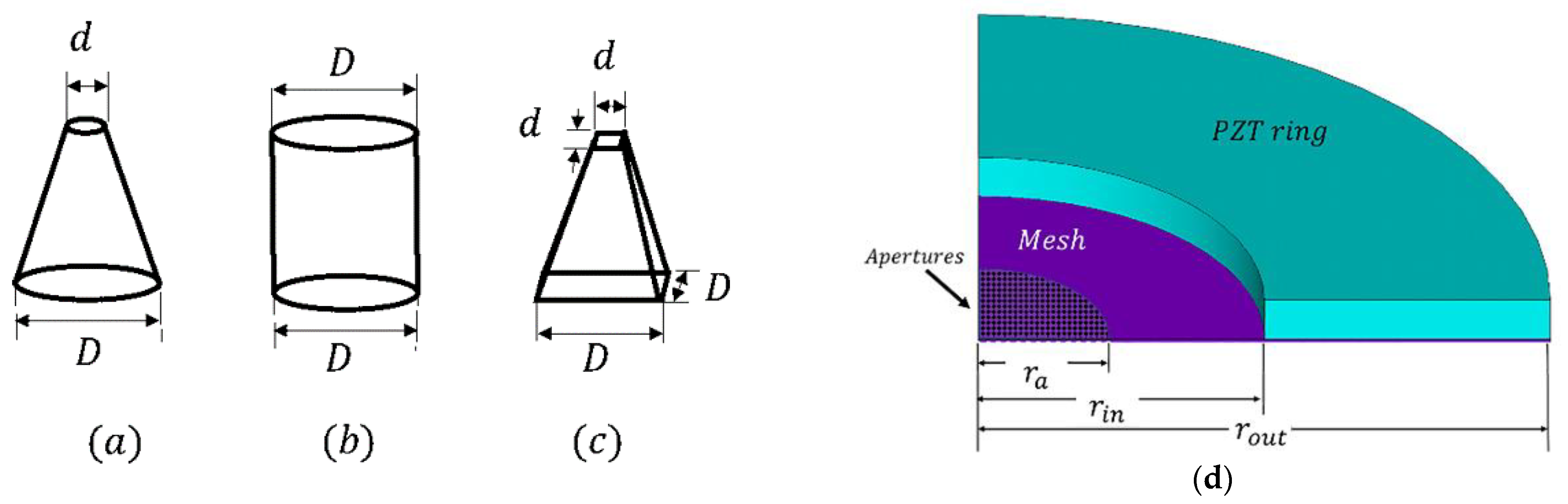
A typical structure of an ultrasonic atomizer is described in
Figure 1. A main component of the system is the mesh (i.e., light gray section), which is formed by a thin plate with a thickness of 50 μm and micro-perforations. The holes are distributed within a circular area with a diameter
. The ring is the piezoelectric actuator (e.g., PZT) with a thickness of about 0.6 mm. A potential difference (voltage) is applied to the piezoelectric ring across the thickness using a signal generator.
and
are the inner and outer diameters of the piezoelectric ring, respectively, and
is the diameter of the disperser or mesh.
The objectives of this work are to first characterize the dynamic behavior of the complete piezoelectric ring and meshed thin plate using FE modeling. Second, the effect of the shape of the micro-apertures on the resonant frequency spectra of the vibrating thin plate is investigated. Last, the numerical simulation results of the atomization rate as a function of the frequency response and voltage are verified using experimental tests. The proposed parametric results could allow to predict and control the atomization rate that can be used to improve the performance of a soft actuation robot.
3. Finite Element Analysis
The dynamic performance of the piezoelectric atomizer and its vibration optimization were studied using a FE analysis. The device was considered as a multi-degree-of-freedom continuum system, which can be represented in a matrix notation as [
6]:
where
and
represent the vector of displacement, velocity, and acceleration, respectively, for every node; [M] is the mass matrix; [C] is the damping matrix; [K] is the stiffness matrix; and
is the external excitation force. Two types of analyses were performed—namely, free and forced vibrations. The modal (free) analysis is an eigenvalue problem assuming no external forces,
. A forced harmonic analysis can also be carried out by applying a frequency sweep for different applied input voltages to the piezoelectric ring.
For the first example, a numerical modal analysis on a stainless-steel circular thin plate was carried out. The mechanical properties of the plate are given in
Table 1. In these calculations, 16,746 elements (SOLID186 with 20 nodes that exhibit quadratic displacement in ANSYS) were used. The boundary conditions of the thin plate were clamped at the edge to the piezoelectric ring, as is shown in
Figure 3. Thus, the displacements in the circumferential area were assumed to be zero (
at
). The simulation was carried out using an FE model implemented in ANSYS; the pseudocode for the analysis is given in
Appendix A.
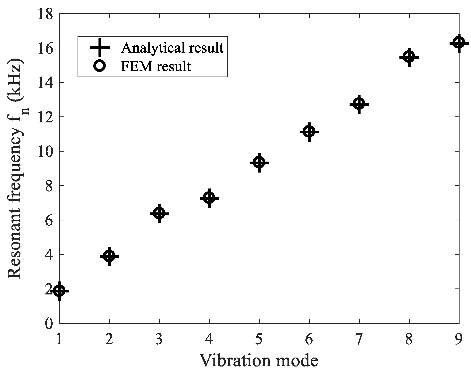
Figure 4 shows the results for the lowest axisymmetric modes when the largest displacement is at the center of the plate. To check the validity of the calculations,
Figure 5 shows the first nine resonant frequencies using the modal analysis of a single, clamped, circular, and homogeneous thin plate. These results are compared with the theoretical approximation given by Equation (5). The results shows that the FE analysis only deviated by ~0.12% on average from the theoretical predictions.
The mechanical behavior of the thin plate is expected to be affected by the loading from the liquid that will be atomized. However, the theoretical and experimental results show that the shape of the vibration modes is not modified; that is, the presence of liquid loading only shifts the values of the resonant frequencies with the invariant shapes of the vibration modes [
21].
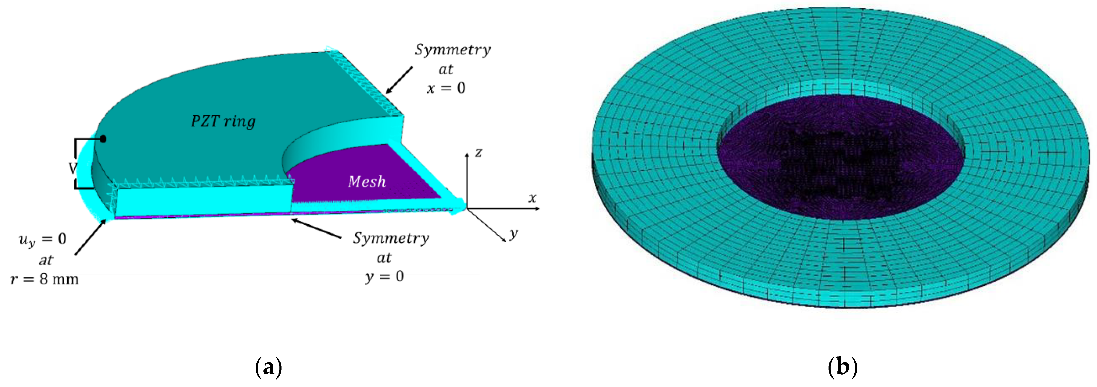
In a preliminary numerical harmonic analysis (see the description of the pseudocode in
Appendix A), a stainless-steel circular thin plate coupled to a piezoelectric ring was modeled. The mechanical, piezoelectric, and physical properties of the materials are given in
Table 1 and
Table 2. The thin plate was modeled as a deformable plate using fully integrated elements with 20 nodes. Due to the symmetry of the model, only a one-quarter model was needed, thus reducing the number of grids and the overall computational demand (see
Figure 6) [
22].
Next, micro-apertures with three different geometrical shapes: cylindrical, pyramidal, and conical were added to the model of the circular thin plate to form a meshed thin plate (thin-plated with micro-apertures), which was then coupled to the piezoelectric ring. The meshed plate contained 551 micro-apertures with the dimensions shown in
Figure 7, where d
and
. These were distributed over the thin plate following a rectangular array.
A forced harmonic analysis with a sinusoidal variation of the voltage was performed on this system as described in
Figure 6. The resonant frequencies of the device and the maximum out-of-plane displacements of the mesh were recorded for the three micro-aperture shape geometries.
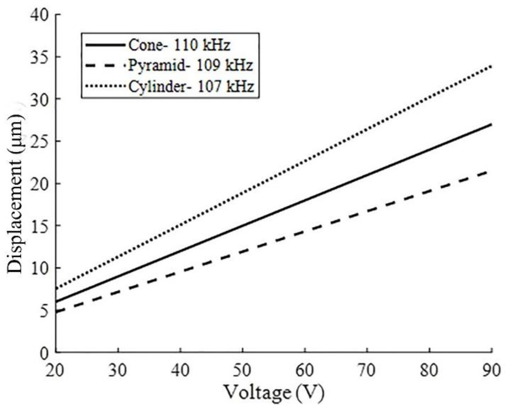
Figure 8 shows a summary of results of the estimated out-of-plane displacement measured at the center of the thin plate against the voltage amplitude applied to the piezoelectric ring when the device was driven at the resonant frequency. The results indicate that the displacement increased linearly with the applied voltage for all three types of aperture shapes. The results show only a small change in the resonance frequency, which seems to be correlated to a loss of density due to the volume removed by micro-apertures in the thin plate, as predicted by the plate theory (Equation (5)). Thus, cylindrical openings with a constant diameter have the largest volume and, also, a resonance frequency, followed by the conical and pyramidal. However, in this work, our focus will be on the conical aperture because of the valveless pumping effect reported in the literature and its better atomization performance [
23].
Table 3 shows the results of FEM analysis with a frequency sweep while applying 80 V to the PZT ring. A cross-section view of the vibration mode shape at the resonance frequency is also shown. These results were obtained using the model of the meshed thin plate with conical shape apertures. The results gave the first five vibration modes. The subscript “s” indicates that the mode was identified as axisymmetric. In all cases, the largest out-of-plane displacements were identified in the center of the meshed thin plate, with a maximum 110-kHz mode found, the value close to those reported for an ultrasonic atomizer, with similar materials reported in Reference [
11].
Figure 9 provides details of the distribution of the displacement through the disk for the axisymmetric vibration mode
obtained at a frequency of 110 kHz and using an applied voltage in the range of
to
. The location of the largest displacement was around the center of the thin plate where the micro-apertures were located. This value of displacement corresponded to the frequency tuning value, with the best performance of the atomizer found in our experimental results (discussed in the Experimental section). The modeling methodology for the atomizer dynamic performance was then used to study the control of the atomization rate by correlating it to the maximum displacements as a function of frequency and voltage amplitudes.
4. Model of Atomization Volume Flow
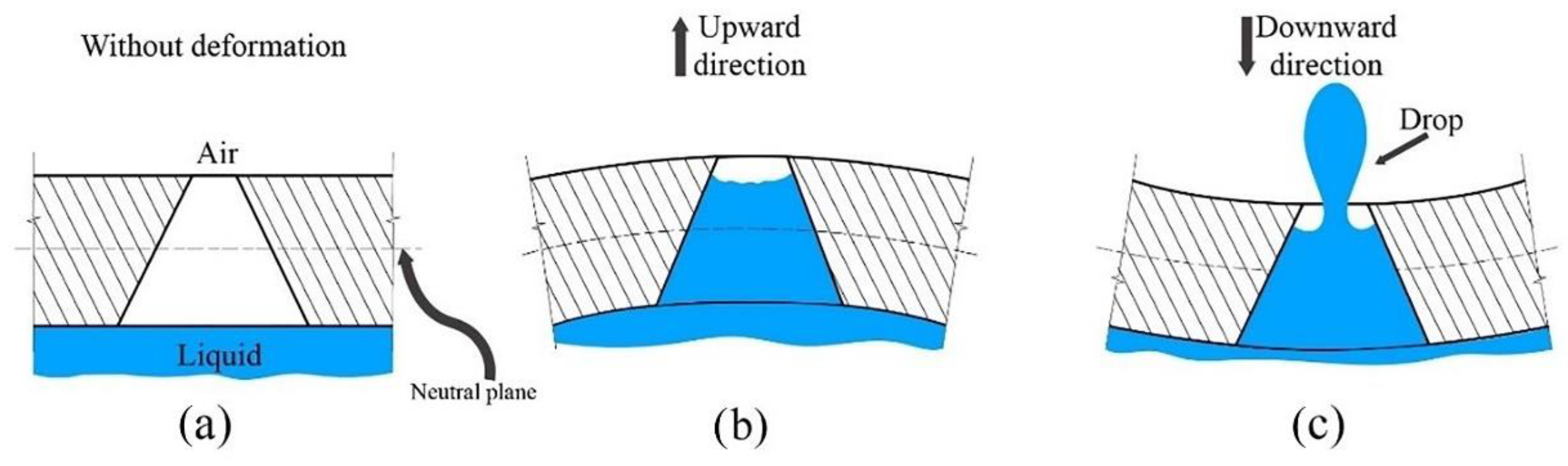
In mesh atomization, the atomizer releases energy into the liquid to break the surface tension and to allow the liquid droplets to escape from the surface. To control the droplet size distribution and to make the atomization process more controllable, micro-apertures are added to form a meshed thin plate driven by a piezoelectric ring. In Maehara et al. [
14], the atomizer performance as a function of the number of micro-apertures was studied. A rough approximation of the deformation for the lowest symmetric modes can be found following the thin plate theory [
24]. The coordinate system assumes that the neutral surface is in the
plane, perpendicular to the
-axis. The flow in the micro-tapered aperture is closely connected with the chamber volume change given by the deformation of the thin plate [
25].
In Cai et al. [
12], the atomization rate was studied, focusing on the effect of the volume change at the liquid chamber (container) due to the deformation of the thin plate during the vibrations at the lowest vibration mode. Additionally, the contribution by the small deformation of the micro-apertures of the mesh during the vibration to the mass flow was studied for that mode. This idea is illustrated in
Figure 10, where the conical micro-aperture deforms by the global deformation of the thin plate. During the periodic vibration, any point on the non-neutral surface moves in two possible conditions. First, the point is bent in the upward direction and then is released back to equilibrium, followed by a compressed state to its lower limit and back to equilibrium. This mechanism acts as a micro-pump, promoting the generation of atomized drops [
26].
Thus, the total flow could have two contributions—namely, one from the global volume change of the thin plate
and another possible from the micro-aperture volume change (
, which could then be expressed as:
where
is the change in the volume in the micro-aperture during vibration that can be obtained by considering the deformation of the neutral surface and the estimation of a triple integral to calculate the change of volume of the micro-cone aperture.
is the corresponding change in volume in the chamber created by the thin plate vibration,
is the oscillation frequency of the plate, and
is a pressure loss coefficient described below. The volume of the atomized liquid displaced by the mechanical oscillation of the plate for the lowest vibration mode is given by Reference [
12]:
where
is the radius of the plate, and
is the thickness of the thin plate. However, since the vibrational modes studied in this work are of a higher order, there is a nonhomogeneous displacement distribution across the radius. In this case, numerical integration techniques were used to approximate the displaced volume, as will be described later. The effective pressure loss coefficient,
, is expressed as:
where
is the pressure loss coefficient related to the diffuser effect, and
is related to the nozzle effect. To relate the volume changes to the mass flow, it is necessary to consider the resistance of the flow through the conical aperture. In a dynamic cycle, the cone aperture acts as nozzle or as diffuser, and the difference between the two flow resistances determines the flow rate. In Zhang et al. [
23], the empirical curves of the cone angle against the diffuser and nozzle pressure loss coefficients on a macroscopic level are given. The pressure loss coefficient is a dimensionless number to characterize the pressure loss in a hydraulic system, which involves pressure loss by friction and by changes in the aperture geometry. In our case, the micro-apertures have a half angle of 35°, which, from the tables reported by Q. Yan et al. [
27], give a loss factor of
and
when the cone acts as diffuser and as the nozzle, respectively. An equation for the net volume flow rate when the throat of the tapered aperture is exposed to the air and the flared side is in contact with the liquid was also reported by Q. Yan et al. [
27]. The equation involves the change in volume of the apertures and the change in volume of the liquid chamber, where
is the number of apertures, and
is the vibration frequency of the PZT.
6. Results and Discussion
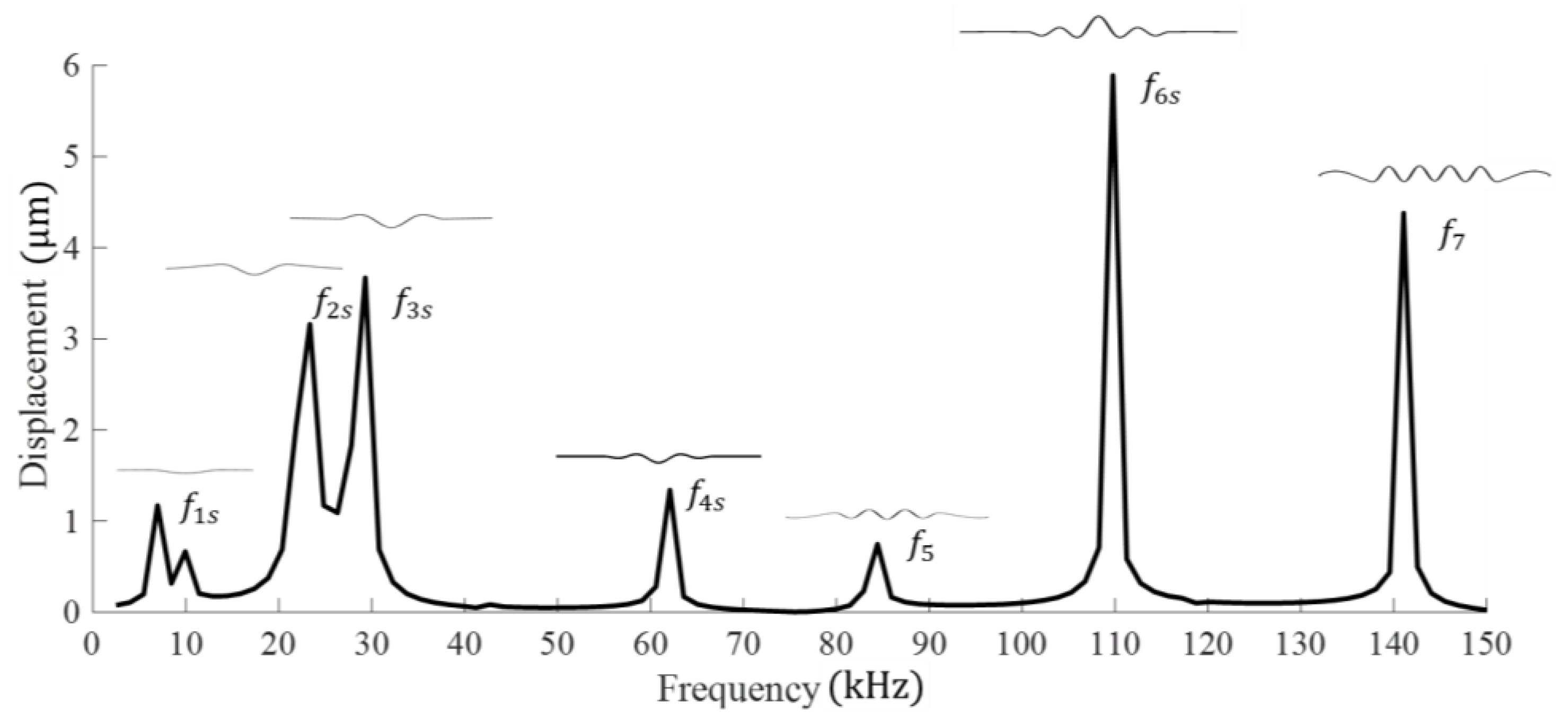
Numerical FEM simulations of the atomizer were performed, and the vibration modes and the resonant frequencies were determined using a forced harmonic analysis (as described in
Appendix A). In particular, a numerical frequency sweep of the system using the physical properties described in
Table 4 was carried out, and the mesh atomizer surface displacements with conical apertures corresponding to different frequencies were estimated and plotted in
Figure 12. The first five resonant frequencies were estimated, and after a further analysis, the vibrational modes with the largest out-of-plane displacements were located at two resonance frequencies of about 110 kHz (
) and 140 kHz (
).
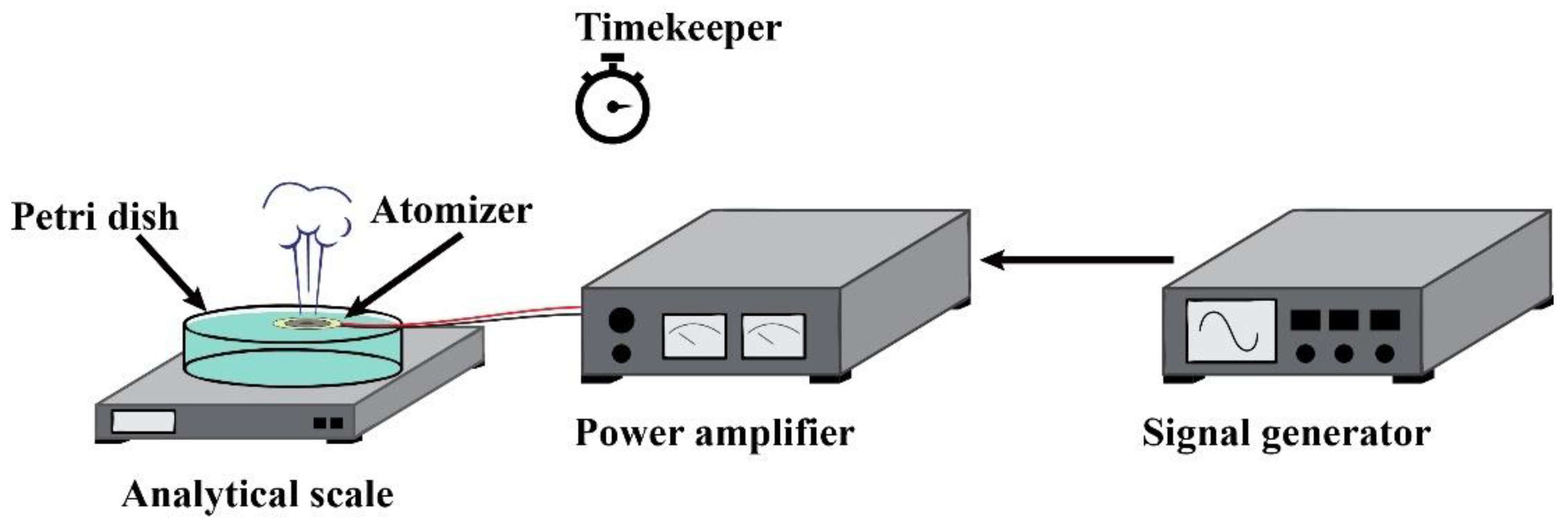
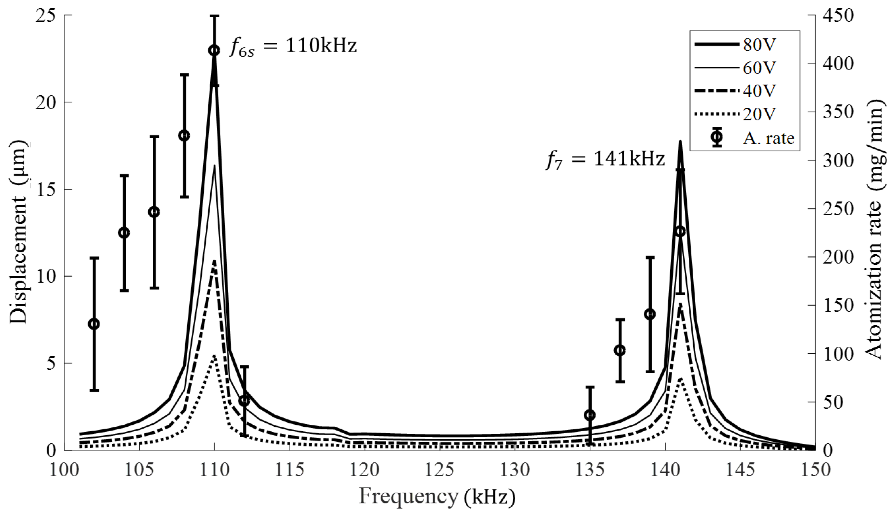
In
Figure 13, the numerical simulation findings (line plots) at various voltage levels (20–80 V) are compared with the experimental results of the atomization rate obtained by a frequency sweep over the range from 100 kHz to 150 kHz. The small discrepancies were expected, as the PZT ring was bonded to the metal mesh using epoxy and the wires were soldered to the system. Overall, the peak atomization rates matched closely with the resonant frequencies from the numerical simulations, with the maxima occurring at frequencies around 110 kHz and 141 kHz. From these results, it is possible to observe that the resonance frequency is not altered with the voltage change; only the amplitude of the central displacement is affected.
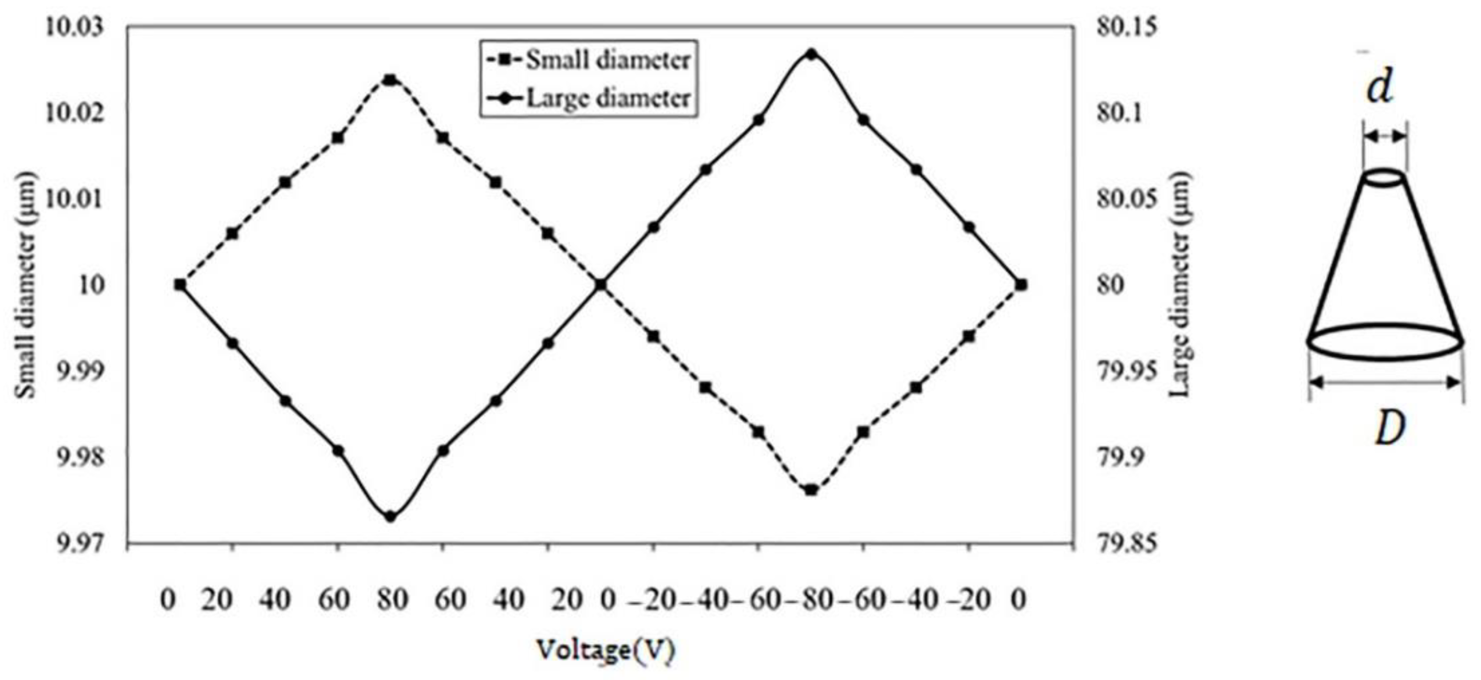
The volume generated by the global deformation of the thin plate
, as well as the additional contribution of the micro-aperture deformations
, were also numerically estimated. The maximum deformation of the micro-aperture located near the center of the thin plate was measured directly from FEM at 110 kHz for the values of the voltage in the range [−80, 80] V, as shown in
Figure 14. A symmetric cyclic behavior of the small (
) and large (
diameters was found; however, these changes were very small (about 0.025
with respect to their initial value at rest. Thus, its contribution to the total value change
was not found to be significant.
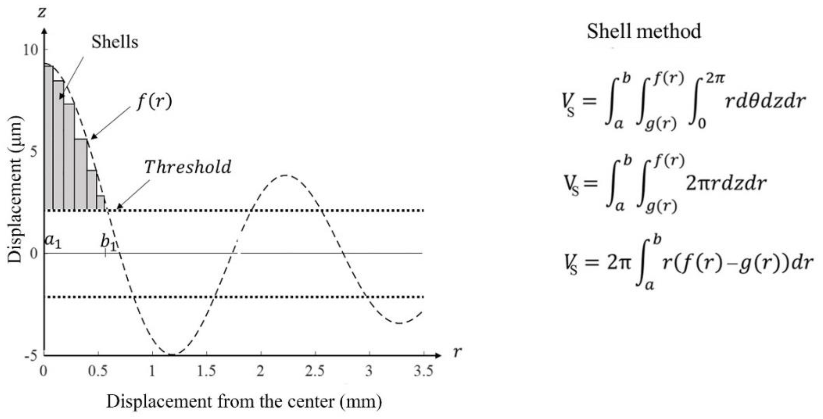
Additionally, the global liquid volume displaced by the thin plate was calculated based on the FEM results (
Figure 15). The distribution of the particle displacement at the surface of the thin plate as given by the FEM was calculated by using the shell method of integration [
28]. An illustration of the integration method considering the limits (
,
) is described in
Figure 15. This method allows obtaining volumes generated by rotating an area between any two functions,
and
, where
is the displacement curve and
is a threshold.
According to our experimental findings, atomization was not detected below 20 V. Therefore, the displacement amplitude (or volume variation) at that value was used as a threshold (
). Thus, the effective volume used for the numerical results was given as
. The changes in volume due to deformation of the apertures
was neglected for the calculations of the atomization rate, since it was very small compared to the total volume change
. On the other hand, the pressure loss coefficient
is difficult to accurately assess its value, since the actual micro-apertures are manufactured by micro-abrasion electroforming and drilling techniques, which, in practice, give irregular conical shapes and edges [
7]. Thus, in order to obtain an estimate of the approximate value of the loss coefficient
, correlated to the experimental atomization rate (
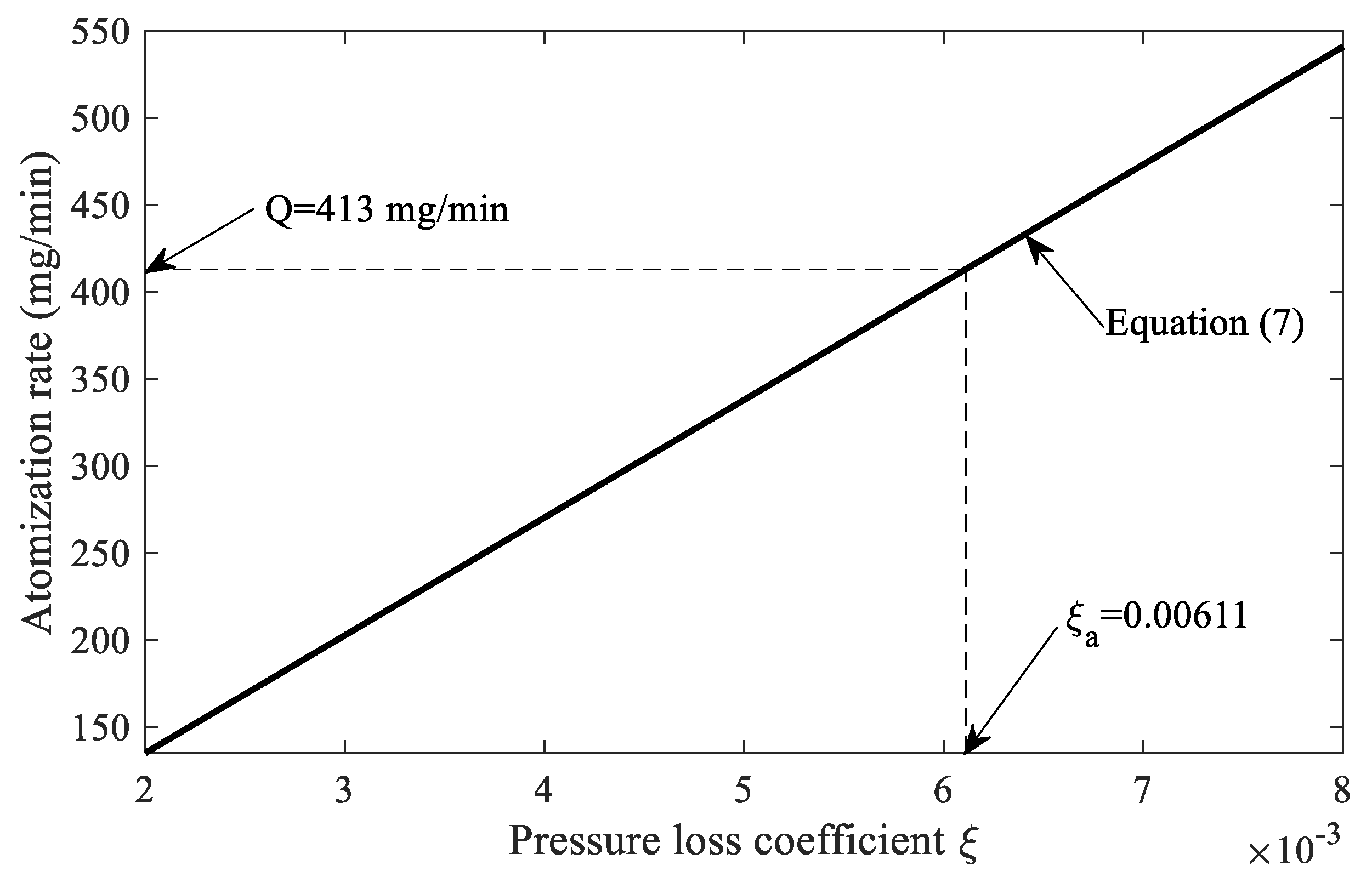
) obtained at 80 V and 110 kHz, the following procedure was implemented.
Figure 16 shows the linear relation (solid line) between the atomization rate and the pressure loss coefficient
as given in Equation (7). By using this linear estimate, an approximate value of
corresponding to the experimentally determined atomization rate (
) was estimated. The value was found to be smaller than the theoretical one (
for an ideal conical shape micro-aperture, but this can be a consequence of the actual conditions found in the micro-apertures of the experimental ultrasonic atomizer.
Using the found loss coefficient (, an approximation of the atomization rate as a function of the voltage can be obtained using Equation (7). The variations of the volume were calculated for every displacement distribution of the thin plate as given by the FEM at the resonance frequency of 110 kHz. For these calculations, the loss coefficient was kept constant.
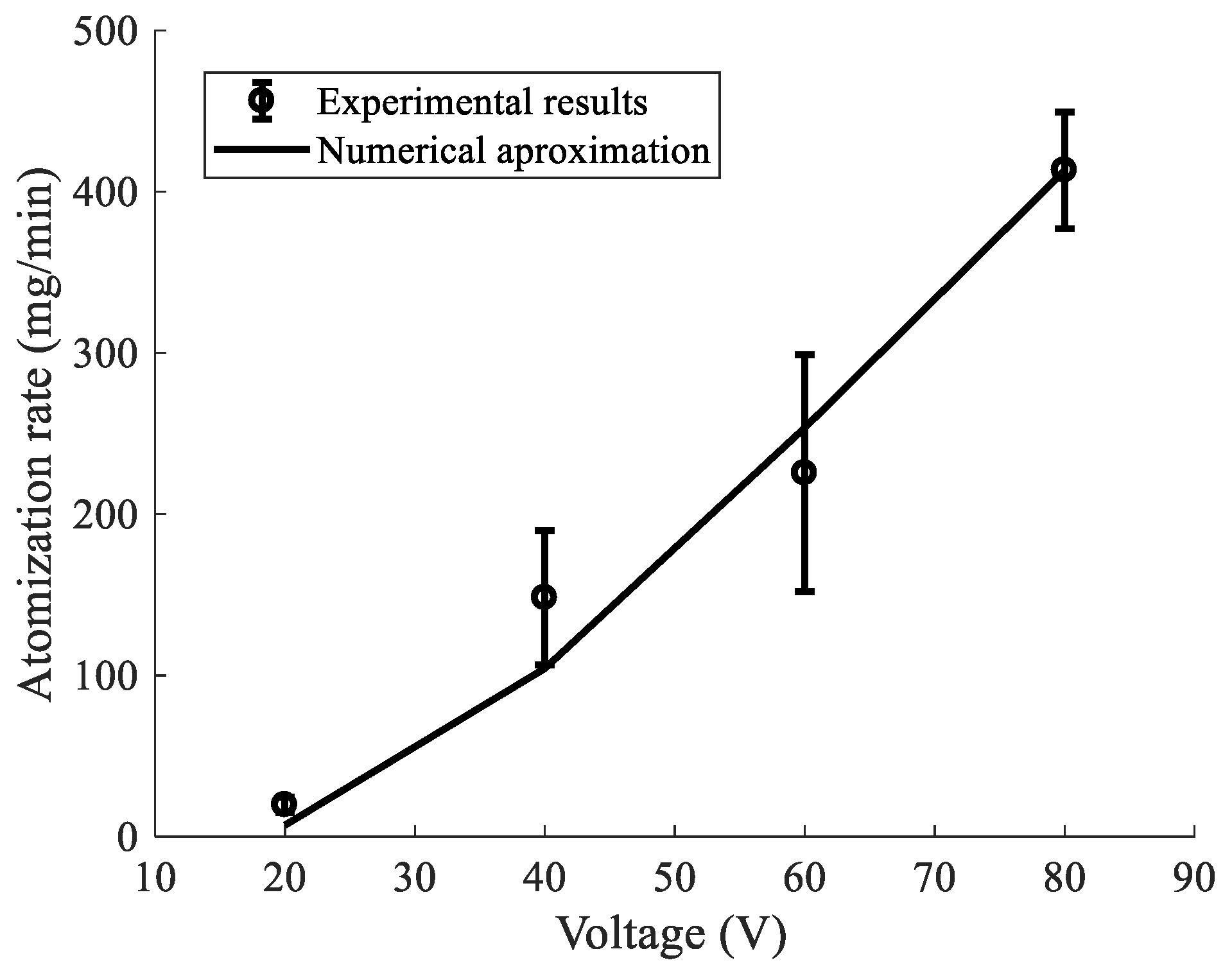
Using these estimations, the results of the atomization rate measurements at the resonant frequency of 110 kHz were compared with the numerical calculations. As it was shown, at this frequency, the displacement amplitude distribution of the vibrational mode was rather complex, with a harmonic decreasing spatial distribution as a function of the thin plate radius. Thus, it is reasonable to assume that the total deformation between the compression and tension cycles was expected to contribute to the atomization rate. In
Figure 17, the obtained results showed a good correlation between the experimental (scatter points) and numerical predictions (solid line) by FEM. The predicted atomization rate was nearly linear, with a minimum at 20 V, which was the preset threshold. A small rate was observed below 40 V, which we attributed to the set constant threshold, thus indicating that the shape of the mode was not affected by the voltage, only its amplitude.
The proposed approach assumes that the coefficient is constant for all voltage values and that the distribution of aperture openings during the dynamic cycles is homogenous over all the area, whilst, in reality, it depends on the vibrational mode behavior. Despite these considerations, it is interesting to notice that the predictions predicted well the experimental results. The predicted behaviors appeared to follow the experimental results with a roughly linear behavior, indicating a directly proportional relationship between the voltage and the out-of-plane displacements through the center of the thin plate, which controls the atomization rate and can be used to optimize it.


