Abstract
Modern machines strive to run at limit performance and dependability while their operational area and size are getting restricted. To achieve those objectives, often swift integration of custom-made subsystems is required, either actuators, sensors, electronic, or SW modules. Such a diverse suite of elements needs specific approaches and tools for fast optimization and adjustment following model-based system engineering (MBSE) and digital twinning principles. The large-scale I-MECH project was an industry-driven initiative striving to give a scientific response to those demands. The intermediate results were summarized in the authors’ previous work. The purpose of this paper is to report on final project results, namely specific performance achievements and figures based on measurable KPIs. After a brief description of key technologies, special focus is given to industrial printing technology based on a generic substrate carrier. However, it is shown that similar and consistent methodology can be applicable in many other industrial domains, such as semiconductors, healthcare robotics, machining, packaging, etc. Thus, the main merit of this survey is a holistic approach to motion control design.
Keywords:
mechatronics; digital twin; application specific integrated circuit (ASIC); electronics; industrial communication; computer vision; low-power sensing; smart system integration; robotics; edge computing; cyber-physical systems; motion control; real-time (RT) control; service-oriented architecture (SOA) 1. Introduction
Recently, imposing technological achievements have been announced in miscellaneous fields of actuation, sensing, control design, MBSE [1,2,3,4,5], and secure communications [6]. They are key drivers of modern the cyber-physical world. As mentioned in [7], those technology areas were developed often independently in the past, hence not respecting generic principles specified by control community [8,9,10] and applicable across domains. In particular, numerous feedback control loops, vertically distributed through several layers, imply strict conditions for all elements of the ecosystem. Hence actual matters in modern machines, in particular their control parts, brought fully new requirements on every part of the whole system including mutual integration. They must be known and accepted within the whole supply chain. Smart mechatronic systems face rising constraints on speed, precision, adaptability, size, self-diagnostic and interoperability while simultaneously needing to accommodate ever more demanding smart cognitive features. Compared to [7], a list of specific challenges can be updated as:
- Computer vision and AI at-the-edge are and will be key enablers for industrial automation/robotics, namely, for fast inspection and motion through vision in-the-loop, sensing feature information, which is not measurable with ‘classical’ techniques. This requires new SoC (System on Chip) and ASIC components.
- Growing flexibility (elasticity) of mechatronic systems together is causing increased presence of residual vibrations [11,12,13]. Together with growing speed, they often overlap with bandwidth required for feedback control.
- Trajectories of robots in general have periodic signatures; therefore, feedback control algorithms should handle ultrafast repetitive disturbances and setpoints [14,15].
- The previous additional energy-effective measurements on moving or rotating parts that can be done only in a wireless way. Thus, fast deterministic industrial wireless communications must be considered in the ‘chain’.
- The robots and mechatronic systems are composed of highly complex kinematic platforms [16] with numerous flexible loads and interacting dependent axes [17]. Consequently, control devices should be capable to execute advanced control strategies (centralized) [18].
- Routine machine adaptation to new environments and new products is necessary, hence self-adaptation principles are requested [19].
- The machines/robots must often work in complex multi-stage production lines (often collaborative) with zero defects, hence must be fully connectable to upper factory layers and provide self-diagnostic/inspection information, i.e., follow Industry 4.0 paradigms. In this context, drive self-diagnostic and performance assessment were identified as essential.
As a response to the above-mentioned challenges, the I-MECH project defined various measurable objectives, which are categorized as scientific and technical (ST), system integration (SI), and system operational (SO) as follows:
ST1: To develop toolchains for utilization of progressive MBSE methods for RT control, design, and automatic assessment of robots while the latest standards for co-simulation are considered, e.g., FMI (functional mock-up interface) [20,21,22,23].
ST2: To develop a smart Instrumentation Layer collecting sensor or visual data from accessory electronic components that are joined to the moving segments of the mechatronic system to increase its available performance [24,25,26] (Section 4).
ST3: To produce interoperable and modular SW and HW building blocks (BB) that are consistent with the SOA paradigm, i.e., smart Control Layer [27,28,29,30] (Section 4).
ST4: To provide connectivity to predictive production planning layer (System Behavior Layer) and create particular self-diagnostic and condition monitoring BBs. They should be executed at the lower layer and gain important information for plant-wide decisions. At ERP/MES layer, data are merged with statistical information and historical patterns to improve actual prediction. It includes a wide range of AI/ML/DL technologies far outside the scope of this paper [31,32,33,34] (Section 4).
SI1: To provide interface for mutual BB connection, considering also electrical routing and/or signal integrity issues [35] (Section 2 and Section 3).
SI2: To verify the platform portability onto motion control hardware that is already on the market [35].
SI3: To verify the platform portability onto industrial robots that are on the market (either with modular or fixed structure) [35].
SO1–SO5: To demonstrate and validate I-MECH pilots in different mechatronic domains:
- Industrial printing (Pilot 1)—Generic substrate carrier (GSC) for digital printing for graphics and/or functional electronics (Section 5.1).
- Semiconductor production (Pilot 2)—A 12-inch wafer stage with high-precision stepping performance (Section 5.2).
- High-speed packaging (Pilot 3)—Tea bag machine for cotton thread knot technology (Section 5.3).
- Big CNC (Pilot 4)—High precision big CNC milling machines (Section 5.4).
- Healthcare robotics (Pilot 5)—X-ray intervention medical manipulator (Section 5.5).
Compared to the majority of research, the principal merit of this work is to offer a more holistic approach to control system design. In particular, the aim is to describe the final results of the project, i.e., fulfillment of stated objectives. It gives a unified approach to the wide range of application, which, after deeper insight and abstraction, suffer from similar problems. Note, that a secondary aim of the paper is to create a link between Master’s degree engineering courses and engineering practice [36]. The analysis confirmed the lack of engineers with relevant knowledge of the market. The project has an immediate impact on the topics of Ph.D. theses and Master’s degree courses [37].
The rest of the paper is organized as follows: Section 2 describes detailed system decomposition of I-MECH objectives into ERP/MES2 pyramid. Section 3 summarizes the overall model-based approach. Section 4 provides an overview of all building blocks (final state) updated according to the final needs defined by pilot applications. Next, Section 5 justifies platform effectiveness on industrial printing application followed by other apps developed during the project. The conclusions and ideas for future work are given in Section 6.
2. Ambitions in System Integration
The main mission of the project was to integrate technology BBs (summarized in Section 4) into complex scenarios that are adjusted for pilots. The results confirmed that the key shortcomings are in interconnections among individual components (Figure 1). Unfortunately, due to insufficient effort devoted to system integration so far [38,39], the developers are typically not considering lots of demands among technological areas, here are few cases:
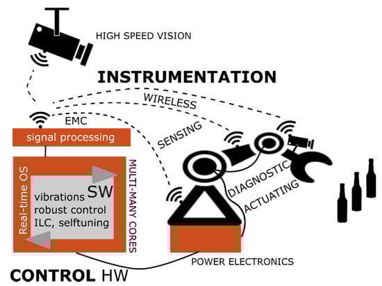
Figure 1.
Selected KETs (key enabling technologies) for advanced mechatronic applications that require fast high-level adjustment and adaptation; they are further represented by BBs in Section 4.
Case 1: progress in wireless industrial sensors and protocols does not concentrate sufficiently on low jitter and synchronization, which is essential when one wants to use such components in fast and precise mechatronic systems.
Case 2: producers of multi-many core platforms usually do not care about growing computational strain of embedded SW, which must be executed in the advanced control HW, etc. There are many more bottlenecks documented in project public outputs [35].
Case 3: computer vision community does not put sufficient effort to deterministic environments where one can use also dynamic model and prediction for object localization.
Case 4: there is a lack of interest inside the feedback control community to provide relevant data from low-level feedback control loops for system diagnostic and predictive maintenance layers.
The project proved that all building blocks should respect top-level requirements defined by machine dynamic performance. More specifically, motion precision and speed were chosen and mapped to required control loop sampling rates, bandwidth, A/D and D/A bit rates, sensor precision, etc. Then, such KPIs (key performance indicators) were projected into individual layers of automation system, see Figure 2. Hence, each building block in the feedback loop chain needs to operate with extremely decreased signal latency (<500 micro-seconds) and point out that the eco-system described is suitable for macroscopic robotic/mechatronic systems with sampling rates up to 50 kHz (examples in Section 5). Apparently, there are lots of micro/nanoscopic technologies working with bandwidths close to megahertz where another type of control modules must be used. However, general modeling/simulation approaches and feedback control algorithms are applicable in those domains as well.
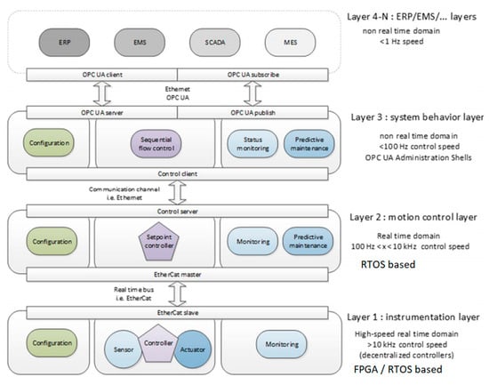
Figure 2.
Structure of control system into layers with different RT and sampling time demands.
3. Concept and Overall Approach
The crucial approach to quick development and adaptation is the wide utilization of novel MBSE toolchains. In addition, the architecture interoperability and modularity are an indispensable drivers for long-term enhancement and growth of MBSE techniques and tools delivered by project members. Thus, the developed architecture with mentioned MBSE toolchains form an eco-system for creating intelligent robotic applications. The relevance of those methods was recently confirmed on pilot machines documented in Section 5.
The set of methods includes the complete fast development cycle that is typically structured into the following steps: MIL (Model-in-the-Loop), SIL (Software-in-the-Loop), PIL (Processor-in-the-Loop), and HIL (Hardware-in-the-Loop) [40]. Despite the fact that the substance of these stages is not fully standardized, the consortium agreed on the approach shown in Figure 3. Our research pushed the state-of-the-art namely in:
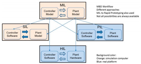
Figure 3.
MBSE approach for rapid development and optimization of mechatronic systems.
- Math-physical multi-domain modeling that allows to include HW, SW, electronic, and mechanical components into one model. Significant attention was given to development of reliable models of complex multi-axes machines. A specific advantage is the overcoming of the rigid-body concept, which is not sufficient to describe behavior of high-tech machines, namely, to deal with residual vibrations and optimize feedback control system.
- Inclusion of FEM (finite-element) models into non-RT simulations and definition of parameter uncertainty. Such approaches bring a non-conservative, optimized robust control design. FEM models help, e.g., to predict resonance and anti-resonance system modes even before the machine is built.
- Virtual models of actuators and sensors and their integration into machine model.
- RT simulation of mechatronic systems, which requires seamless model reduction techniques and complex model verification [41].
- Parametric identification from signals obtained on the controlled device and merging data with mathematical-physical models. These methods were shown to be essential for underactuated robotic systems (even unstable), see e.g., [42].
Such ideas were approved as cornerstones for developing multi-layer digital twins of industrial sites (and mechatronic devices) that ’live’ in real-time with the real system.
4. Building Blocks and Methodology
In the upcoming section, developed BBs are described, including their core functionalities. They are decomposed as summarized in Section 4.12. Their development was scheduled as two iterations, where the first one is done mainly via model-in-the-loop approach (non-RT, virtual simulation). The next iteration delivered mature components including all SW, HW, sensors, and electronics (see use cases in [35]). Selected BBs relevant for Pilot 1 are described in more detail.
4.1. Smart Sensor Data Processing Unit (BB1)
BB1 serves as an integrating platform for smart sensors (Figure 4). It delivers high-fidelity data gained from the primary sensor raw information. Assumed sensors have various physical bases—e.g., inertial like gyroscopes and accelerometers; magnetic; optical, including interfaces to high-speed vision modules. Thus, several electrical interfaces are supported, also counting connection to the wireless modules (see BB2). The SoC + FPGA platform can filter raw sensor data with higher sampling rates higher than 10 kHz. Consequently, from the control structure perspective, it is a suitable fast platform for Layer 1, which can even implement lower feedback control loops (e.g., velocity). In order to simplify programming, compatibility with MathWorks programming toolchains was ensured [43].
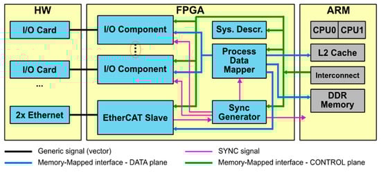
Figure 4.
System structure of BB1 and interfaces to other BBs.
4.2. Real-Time Wireless Sensors (BB2)
BB2 can be considered as an I/O expansion of BB1. It implements fast wireless network ensuring secure, synchronized, and reliable data transfer from sensors to the master node (or central computing module) in an energy efficient way [44]. Fast update rates and low latency allow complex control methods utilizing auxiliary load-side sensing to be implemented. Moreover, the measurement precision is improved. In general, the purpose of the BB2 real-time wireless sensor is to acquire the data from sensors (e.g., accelerometer, force, etc.) with as low as possible latency (<500 us), while ensuring reliable data transmission and low power consumption. BB2 real-time wireless sensor consists of seven key elements: microcontroller (MCU) for data management, a wireless communication module for wireless data transmission, accelerometer (Acc) (+ interfaces to external sensors) for data acquisition, USB/Serial Port for configuration and data collection, and Li-Ion Battery to operate autonomously, as well as long distance (>20 cm) wireless charging module (Figure 5).
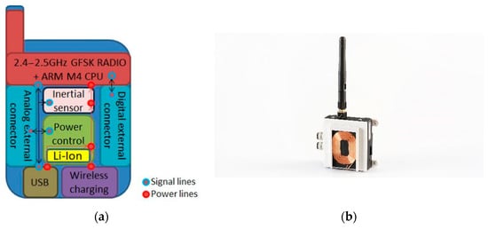
Figure 5.
BB2 final design: system structure (a), real device (b).
4.3. Robust Condition Monitoring and Predictive Diagnostics (BB3)
BB3 module is capable to check continuously the performance of a mechatronic device and to inform on its actual and future trends [24,25,45]. BB3 exploits measured data of vibrations and acoustic emission and provides the machine health monitoring via a set of smart algorithms. The reports brought by this component are further communicated to Layer 2 for execution profile adapting (typically to decrease the workload of a subsystem that is going to fail). In Layer 2, information fusion with BB6 is done, data are pre-processed and sent to Layer 3 ERP/predictive maintenance platforms for plant-wide production planning.
4.4. High-Speed Vision (BB4)
BB4 implements vision modules that provide camera data, in particular for feedback-based trajectory tracking. The core idea is the utilization of high-speed cameras with integrated data processing towards mechatronic and robotic systems. For integrated, robust control of industrial systems, system on chip (SoC) BB4 architecture was developed. This system provides capturing raw images, fast image processing, and transformation into requested geometric info (e.g., velocity and position of a chosen item in the image) in one module. This building block is an advanced module for Layer 1 that can be used in a robot control setups, it is pluggable to building block 1. In applications where the price is a more significant project driver, an SoC solution comes as an alternative to the high-end variant. Examples of such a SoC are the Nvidia Jetson TX2 and Xavier. These feature multiple ARM cores (instead of Intel). The camera interfaces are CSI-2 and USB3 (instead of CoaXPress). This also enables the selection of less expensive cameras for the application.
4.5. High Performance Servo Amplifier (BB5)
This building block brings highly configurable, high performance current amplifier for motion control applications. More specifically, it is a customizable low-level servo drive control in Layer 1, which can be embedded into high-precision mechatronic platforms with stringent performance demands (e.g., mA-current accuracy and/or 200–500 Hz position bandwidth). It features the most advanced transistor technology for the highest power density efficiency and providing almost ‘linear’ motion drive/amplification performance, while better energy efficiency than a silicon-based PWM amplifier. This new technology is based in a GaN FETs (Gallium Nitride Field Effect Transistors) power stage that allows the ultra-miniaturization of the motion drive/amplifier reaching an extremely high performance that has not been achieved in the industry yet.
4.6. Self-Commissioning Velocity and Position Control Loops (BB6)
This module implements SW code for self-identification of the controlled device and auto-tuning of the position and speed control loops [19]. In such a way, a control system reacts to variable machine dynamics [46]. Consequently, it has a role in diagnostic and maintenance planning. BB6 is embedded as set of SW components into the overall platform, i.e., can be executed via BB10 or BB1. Building block 6 assesses the actual machine performance quality from the perspective of the Control Layer.
4.7. Vibration Control Module (BB7)
This building block focuses on suppression of unwanted oscillations induced by the motion typically via mechanically compliant driven load. Experimental identification of the mechatronic system dynamics is followed by an auto-tuning of feedback motion control loops (see also BB6). This building block is a simple module usable by any of the pilot applications. Both passive and active vibration techniques were developed in the project. They are based on input shaping filters, input/output inversion, acceleration feedback, and model predictive control. The particular method is selected based on the technology and frequency properties of the application [47,48].
4.8. Model-Based Robust Multivariable Control (BB8)
BB8 implements the key methodology for feedback control loops. Moreover, it takes care of all of the information and technologies generated by previously described building blocks. It includes math equations of the machine dynamics, which are used either for consequential XIL-based control design. Additionally, this BB includes SW blocks for high-precision motion control of complex machines (often multi-axis). It uses data about the machine dynamics obtained from the above-mentioned math models. The methods include also interaction analysis of input/output feedback signals. Note that such analysis was necessary, e.g., for Pilot 1 (generic substrate carrier). Considering diagnostic features, building block 8 can detect significant deviations between the math model and a reality. It can optimize both feed-forward and feedback control parts [49,50].
4.9. Iterative and Repetitive Control Module (BB9)
Building block 9 focuses explicitly on controlled systems that perform repetitive/iterative tasks (ILC/RC) either in terms of reference trajectories or disturbances [51,52]. Developed SW function blocks include complex ILC/RC schemes with a self-commissioning “service” that is beneficiary for different motion control applications having periodic character. When damping known periodic disturbances, it can monitor their variations (also via BB6 tools) and send alarms/reports to Layer 3. BB9 is compatible with the overall platform. In the project, the research was focused on basic ILC strategies, model-based ILC strategies, model-based repetitive control, and PID-based repetitive control. RC was a key element in general substrate carrier optimization.
4.10. Control Specific Multi-Many Core Platform (BB10)
BB10 brings a customizable hardware board convenient for execution of the SW modules described in previous subsections. It is able to work with complex BB structures by delivering an open, customizable, or COTS multi-many core platform for control algorithms execution [17,53]. In the context of the well-known automation pyramid, BB10 provides a HW and SW bridge to Layer 3.
4.11. Real-Time Operating System (RTOS) (BB11)
To ensure predictably mastering the parallel computing bandwidth provided by modern computing systems, it is essential to equip existing real-time operating system via scheduling approaches to decrease the interference due to the simultaneous execution of many tasks on individual cores, concurring for the access to the shared HW and SW resources [17,53,54,55,56]. In contrast to that, industrial applications need the chance to execute the actual control code base with little modification, therefore, we propose the usage of a hypervisor level to isolate different domains trying to provide enhanced guarantees. The key research activity concerned the hypervisor block, together with predictable scheduling algorithms and execution models integrated into open source RTOS.
4.12. Overall BB Integration
The BBs described can effictivelly work together and create universal platform for various application domain as shown in Figure 6.
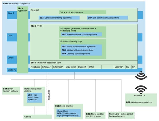
Figure 6.
Motion control platform decomposition into BBs and Layers.
5. Pilot Applications and Key Results
This section provides a brief description of the main applications (see Figure 7). More details are provided for Pilot 1 (GSC) where the performance improvement is justified via relevant figures. Note that full technical details are subject to product IPRs, i.e., are confidential.
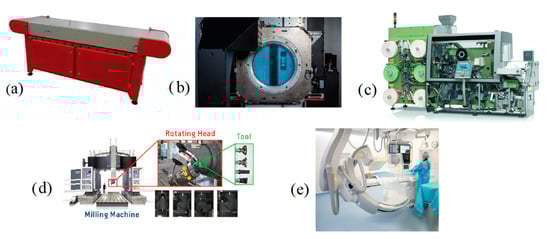
Figure 7.
List of application areas where developed building blocks and platform were validated and implemented: (a) Pilot 1—Generic substrate carrier, (b) Pilot 2—12-inch wafer stage, (c) Pilot 3—High-speed packaging machine, (d) Pilot 4—Big CNC machine, (e) Pilot 5—Medical manipulator.
5.1. Generic Substrate Carrier
5.1.1. Overall GSC Description
The Generic Substrate Carrier (GSC) is a stainless-steel conveyer belt for the highly accurate transport of substrates (Figure 8). It is capable of transporting practically any kind of substrate, such as paper, cardboard, or foils, but also wooden or glass panels. The device is particularly suited for the industrial inkjet market, which is expected to exploit the GSC for the emerging 1200 × 1200 DPI registration challenge. Manufacturing equipment for single-pass digital printing faces an interesting challenge to deal with the growing productivity demand in combination with rising droplet registration accuracy. Although the administration speed of print-heads is still increasing, high throughput speeds and/or increased print resolution can only be achieved by using multiple heads in series. When using at least four different inks, the distance between the first and last print-head can become more than one meter. The GSC can meet the challenge when the relative registration accuracy over such a distance must be less than ten micrometers. The substrate carrier utilizes a stainless-steel conveyor belt in order to eliminate the mechanical (e.g., elasticity) properties of the substrate and prevent deformation of the substrate during transport. The substrate is clamped on the conveyor belt using vacuum technology. Many conventional steel conveyor belts and their steering systems cannot reach the previously mentioned accuracy target. During rotation, a belt will (always) translate axially with respect to the rollers of the conveyor due to imperfections in manufacturing of the belt and/or roller (e.g., accuracy of the weld perpendicularity). The GSC uses movable segmented rollers to actively control the position of the belt without deforming the belt. This allows accurate position control of transported substrates without deformation of the substrate over a long distance, which is essential for the digital single-pass inkjet industry.
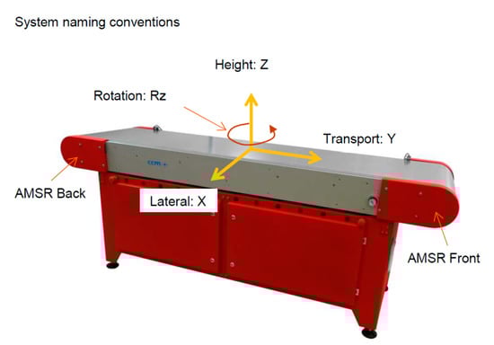
Figure 8.
Pilot 1—Generic Substrate Carrier (GSC) motion axis configuration.
5.1.2. Application of Project BBs to GSC (Pilot 1)
The overall scheme of BBs application is shown in Figure 9. Firstly, As GSC is a multi-input multi-output (MIMO) system, it was necessary to check, whether there are significant cross-relations between I/O signals and consequently if decoupling filters are necessary to use. This kind of identification procedure is a part of BB8. The procedure at the system level is depicted in Figure 10.
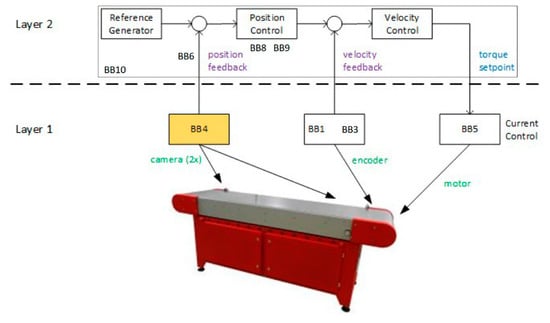
Figure 9.
Pilot 1 = GSC overall control system structure and utilization of BBs.
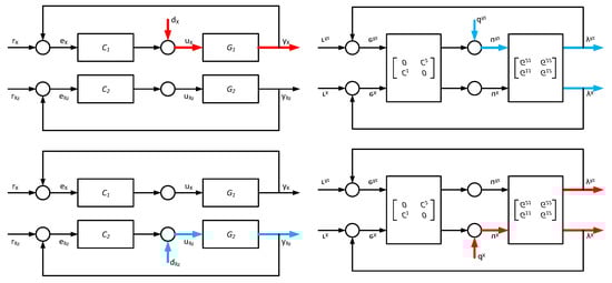
Figure 10.
Pilot 1 GSC system identification: (Left)—traditional way (before the project); (Right)—BB8 MIMO identification (at the end of the project).
Next, high quality sensors signals must be delivered to ensure optimal control. Figure 11 below shows results that were created during one of the auto-calibration routines. The upper picture shows detected “voids” in a measured sensor signal that needs to be filtered out. The bottom picture shows the result of the same sensor after the auto-calibration, measured in a validation measurement that is part of the routine.
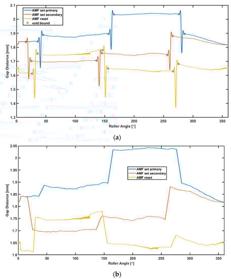
Figure 11.
Example of typical BB6 auto-calibration routine results. (a) Detection analysis output; (b) Validation result after calibration.
Finally, repetitive control was the technology (BB9) that brought the biggest impact to machine performance improvement. The key idea is a “memory buffer” in addition to the classical feedback loop, which allows to adapt the system to periodic disturbances of known period while the periodic part of the tracking error tends to zero. Although the method is theoretically well explored, the real implementation always brings a lot of problems namely in designing additional filters L (learning filter) and Q (robustness filter) ensuring the stability of the main feedback loop (Figure 12). The performance improvement of GSC is shown in Figure 13 in the context of tracking error. When depicting in the form of cumulative power spectral density for the X-axis, one can observe a 40% improvement at higher frequencies (Figure 14).
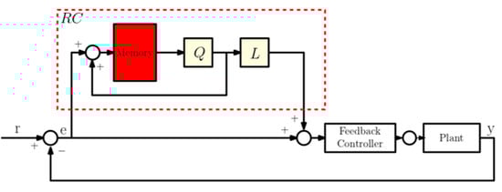
Figure 12.
Pilot 1—GSC position-based repetitive control scheme (BB9).
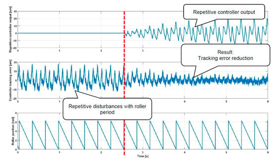
Figure 13.
Pilot 1—GSC performance improvement based on repetitive control (BB9). Red line marks time when the controller was switched on. Pilot 1—GSC cumulative power spectral density (CPSD) of tracking error, 40% improvement based on repetitive control.
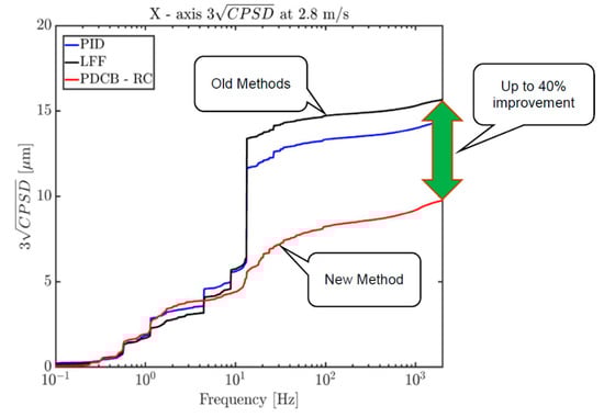
Figure 14.
Pilot 1-GSC cumulative power spectral density (CPSD) of tracking error, 40% improvement based on repetitive control.
The list of other BBs applied on GSC is shown in Table 1.

Table 1.
BB implementation on selected pilots. Y—BB was implemented.
5.2. 12-Inch Wafer Stage (Pilot 2)
The 12-inch wafer stage is a main component in the ADAT XF range of small-die-high-volume semiconductor die bonding machine [57,58]. It provides ultra-highspeed (72,000 units/h) and high-accuracy (3 micro-meters) positioning of a wafer containing semiconductors to enable high-throughput and high-precision component placement in relevant sub-systems of the whole device. The wafer stage needs synchronization of seven drives, some of which work with interacting axes. Firstly, improved data reading from encoders was proven using BB1. Next, fast EtherCAT communication was validated using high performance current amplifiers (BB5). Finally, performance improvements based on smart control algorithms (BB6, BB9) are documented in project deliverables.
5.3. In-Line Filling and Stoppering Machine, Tea Bag Machine (Pilot 3)
Tea bag machine is used for filling liquid solutions into cylindrical vials and for rubber stopper insertion as a part of complex packaging system [59,60]. Multi-many-core platforms are not developed enough to ensure the strict RT conditions of the machine, due to the mutual interferences of tasks simultaneously running on individual cores, and concurrently accessing shared resources like I/O devices, network interfaces, GPU accelerators, and shared data structures. The described project integrated the latest research results from the RTOS community (hypervisor-based solutions) in the implementation of multi-core (RTOS) and execution models to reach a predictable execution for the filling machine (BB10, BB11).
5.4. Smart Machining Tools and Milling Machines (Pilot 4)
Smart milling machines (CNC-based) are optimized for high-productivity domains such as energy, aeronautics, automotive, mold, and dies [61,62,63]. The milling head is one of the most important modules having direct impact on production quality. Smart wireless nodes able to collect RT data about a machine’s milling head performance were developed. At system level, the sensors follow the structure of BB2. This set of sensors includes accelerometer-based vibration sensors, proximity sensors, wireless temperature probes and embedded electronics data pre-processing.
5.5. Medical Manipulator (Pilot 5)
Robots and manipulators used in the medical sector create lots of applications with typical signature and requirements [64,65]. It is common that time constant controllers (with single set of parameters) are not able to handle the full span of applicable loads, which creates a need for BB6. Although the requirements such as bandwidth and speed may be limited, robustness is critical, apparently. It has more aspects: robustness over a longer period of time (months, years) and robustness with respect to control performance. Both of them are important in the medical segment. A medical robot available at the market (with 5DOF) was employed for the verification of advanced motion control structures and condition monitoring, i.e., to validate the quality of described building blocks.
Let us mention, that besides pilots, the building blocks are verified also in industrial robotics, metal processing machines, or hoist and crane domain. They are called technology use-cases and demonstrators. Full details about all success stories are documented in [36].
6. Conclusions
6.1. Summary of Project Results
This paper documented that performance boundaries in mechatronic systems with moving elements are often created by shortcomings in fast integration of highly interoperable subsystems (sensors, SW, HW, actuators, etc.). Let us mention that the applications described are currently on the market. The request for novel building blocks and toolchains for integration rise up from the need to put those devices on the higher quality class, i.e., make them leading products. The platform was successfully validated on several pilot apps. In this paper, particular performance improvements are shown for the generic substrate carrier. In contrast to other research, this paper provides a more holistic approach and kind of “minimal set” of building blocks that must be considered when employing complex feedback control.
During an intensive three-year collaboration, a reference platform was defined to provide the envisioned MBSE approach, whilst keeping up a seamless integration of BBs. The project architecture is structured into three layers. The partners have learned that every layer should use its specific toolchain to facilitate the MBSE paradigm at all layers. The BBs are accessible through a (central) repository, which is managed in secure way. It requires a complex IT&S support to make the tools available for other partners. Sioux Technologies and other partners continue to nurture this concept. The so-called I-MECH Center aims to develop, simulate, customize, and verify applications with described building blocks.
6.2. Future Work
Clearly, technological innovations are very fast. Consequently, there already exist the next drivers for future collaboration, e.g.,: utilizing machine learning and AI at top layers of a control system to support integrated predictive maintenance and zero-defect production; high-fidelity simulation and modelling approaches, which enable digital twins to be “living” and cover full product lifecycle, multi-domain, and multi-layer modeling; supporting XIL standard, which could unify validation of modules of a numerous individual suppliers; full integration of new actuators and sensors. Apparently, there is great interest for sustainable collaboration under the upcoming EU research program. The consortium was extended (new competencies are needed) and we are looking forward to the start of the consequential IMOCO4.E project (September 2021).
Author Contributions
Conceptualization and methodology, M.Č. and A.-J.B.; Validation, K.O.; Data curation, A.-J.B.; Writing—original draft preparation, M.Č.; Writing—review and editing, A.-J.B. and K.O. All authors have read and agreed to the published version of the manuscript.
Funding
This work was supported by the H2020 ECSEL JU grant agreement No. 737453 I-MECH project ‘Intelligent Motion Control Platform for Smart Mechatronic Systems’ and by ECSEL Joint Undertaking (JU) under grant agreement No 826610. This Joint Undertaking received support from the European Union’s Horizon 2020 research and innovation program and Czech Republic, Belgium, France, The Netherlands, Latvia, Spain, Italy, Greece, Portugal, Austria, and Ireland. The support is gratefully acknowledged.
Institutional Review Board Statement
Not applicable.
Informed Consent Statement
Not applicable.
Data Availability Statement
Not applicable.
Conflicts of Interest
The authors declare no conflict of interest.
Abbreviations
| MBSE | Model-based system engineering |
| KPI | Key performance indicator |
| AI | Artificial intelligence |
| SoC/ASIC | System on Chip, Application specific integrated circuit |
| FMI/FMU | Functional mock-up interface/functional mock-up unit |
| BB | Building block |
| GSC | Generic substrate carrier |
| CNC | Computer numerical control |
| ERP/MES | Enterprise resource planning/Manufacturing execution system |
| A/D D/A | Analogue/Digital |
| KET | Key Enabling Technologies |
| MIL/SIL/PIL/HIL | Model (Software, Processor, Hardware) in the Loop |
| FEM | Finite element model |
| FPGA | Field programmable gate array |
| MCU/GPU | Micro-controller unit, general processing unit |
| GaN FET | Gallium Nitride Field Effect Transistors |
| CSI | Camera serial interface |
| ILC/RC | Iterative learning/repetitive control |
| SOA | Service oriented architecture |
| PID | Proportional—integral—derivative |
| RTOS | Real-time operating system |
| MIMO | Multi-input multi-output |
| CPSD | Cumulative power spectral density |
| COTS | Commercial off the shelf |
| DOF | Degree of freedom |
| ML/DL | Machine learning, Deep learning |
References
- Sabanovic, A.; Ohnishi, K. Motion Control Systems; John Wiley and Sons: Hoboken, NJ, USA, 2011. [Google Scholar]
- Kwon, S.; Chung, W.K. Perturbation Compensator Based Robust Tracking Control and State Estimation of Mechanical Systems; Springer Science and Business Media: Berlin/Heidelberg, Germany, 2004. [Google Scholar]
- Van Dooren, P.; Wyman, B. Linear Algebra for Control Theory; Springer Science and Business Media: Berlin/Heidelberg, Germany, 2012; Volume 62. [Google Scholar]
- Milovanovic, D.; Rao, K.; Bojkovic, Z. Wireless Multimedia Communications; CRC Press: Boca Raton, FL, USA, 2008. [Google Scholar]
- Gene, F.; Franklin, J. David Powell, Abbas Emami-Naeini: Feedback Control of Dynamic Systems, 8th ed.; Pearson: London, UK, 2018. [Google Scholar]
- Akeela, R.; Elziq, Y. Design and Verification of IEEE 802. 11ah for IoT and M2M Applications. In Proceedings of the 2017 IEEE International Conference on Pervasive Computing and Communications Workshops (PerCom Workshops), Kona, HI, USA, 13–17 March 2017. [Google Scholar] [CrossRef]
- Cech, M.; Beltman, A.-J.; Ozols, K. I-MECH—Smart System Integration for Mechatronic Applications. In Proceedings of the 2019 24th IEEE International Conference on Emerging Technologies and Factory Automation (ETFA), Zaragoza, Spain, 10–13 September 2019; pp. 843–850. [Google Scholar] [CrossRef]
- Sinha, S.; Koedam, M.; Breaban, G.; Nelson, A.; Nejad, A.B.; Geilen, M.; Goossens, K. Composable and predictable dynamic loading for time-critical partitioned systems on multiprocessor architectures. Microprocess. Microsyst. 2015, 39, 1087–1107. [Google Scholar] [CrossRef]
- Yin, K.; Zhong, C. Data collection in wireless sensor networks. In Proceedings of the 2011 IEEE International Conference on Cloud Computing and Intelligence Systems, 2011 and Automation, Beijing, China, 15–17 September 2011. [Google Scholar]
- Tsuji, T.; Hashimoto, T.; Kobayashi, H.; Mizuochi, M.; Ohnishi, K. A Wide-Range Velocity Measurement Method for Motion Control. IEEE Trans. Ind. Electron. 2009, 56, 510–519. [Google Scholar] [CrossRef] [Green Version]
- Singhose, W. Command shaping for flexible systems: A review of the first 50 years. Int. J. Precis. Eng. Manuf. 2009, 10, 153–168. [Google Scholar] [CrossRef]
- De Luca, A.; Schroder, D.; Thummel, M. An Acceleration-based State Observer for Robot Manipulators with Elastic Joints. In Proceedings of the 2007 IEEE International Conference on Robotics and Automation, Rome, Italy, 10–14 April 2007. [Google Scholar] [CrossRef]
- Zirn, O.; Jaeger, C. Vibration damping for machine tool servo drives by load acceleration feedback. In Proceedings of the 2010 IEEE International Symposium on Industrial Electronics, Bari, Italy, 4–7 July 2010. [Google Scholar] [CrossRef]
- Bristow, D.; Tharayil, M.; Alleyne, A. Survey of iterative learning control: A learning-based method for high-performance tracking control. IEEE Control Syst. 2006, 26, 96–114. [Google Scholar]
- Wang, C.; Zheng, M.; Wang, Z.; Peng, C.; Tomizuka, M. Robust iterative learning control for vibration suppression of industrial robot manipulators. J. Dyn. Syst. Meas. Control Trans. ASME 2018, 140, 011003. [Google Scholar] [CrossRef]
- Smith, C.; Karayiannidis, Y.; Nalpantidis, L.; Gratal, X.; Qi, P.; Dimarogonas, D.V.; Kragic, D. Dual arm manipulation—A survey. Robot. Auton. Syst. 2012, 60, 1340–1353. [Google Scholar] [CrossRef] [Green Version]
- Goubej, M.; Schlegel, M. Robust PID Control of Electrical Drive with Compliant Load. In Proceedings of the IFAC World Congress, Cape Town, SA, USA, 24–29 August 2014; Volume 47, pp. 11781–11786. [Google Scholar]
- Valencia, J.; Goswami, D.; Goossens, K. Composable Platform-Aware Embedded Control Systems on a Multi-core Architecture. In Proceedings of the 2015 Euromicro Conference on Digital System Design, Funchal, Madeira, Portugal, 26–28 August 2015; pp. 502–509. [Google Scholar]
- Giacomelli, M.; Colombo, D.; Finzi, G.; Setka, V.; Simoni, L.; Visioli, A. An autotuning procedure for motion control of oscillatory mechatronic systems. In Proceedings of the 2019 24th IEEE International Conference on Emerging Technologies and Factory Automation (ETFA), Zaragoza, Spain, 10–13 September 2019; pp. 829–835. [Google Scholar] [CrossRef] [Green Version]
- Reitinger, J.; Čech, M.; Königsmarková, J. Model-based control system design for steam turbine based on Functional Mock-up interface (FMI/FMU). In Proceedings of the 2018 19th International Carpathian Control Conference (ICCC), Miskolc, Hungary, 28–31 May 2018; Institute of Electrical and Electronics Engineers (IEEE): Piscataway, NJ, USA, 2018; pp. 559–564. [Google Scholar]
- Simoni, L.; Beschi, M.; Legnani, G.; Visioli, A. On the Inclusion of Temperature in the Friction Model of Industrial Robots. IFAC-PapersOnLine 2017, 50, 3482–3487. [Google Scholar] [CrossRef]
- Simoni, L.; Beschi, M.; Legnani, G.; Visioli, A. Modelling the temperature in joint friction of industrial manipulators. Robotica 2019, 37, 906–927. [Google Scholar] [CrossRef] [Green Version]
- Čech, M.; Königsmarková, J.; Reitinger, J.; Balda, P. Novel tools for model-based control system design based on FMI/FMU standard with application in energetics. In Proceedings of the 2017 21st International Conference on Process Control (PC), Strbske Pleso, Slovakia, 6–9 July 2017. [Google Scholar] [CrossRef]
- Dosedel, M.; Havranek, Z. Design and performance evaluation of smart vibration sensor for industrial applications with built-in MEMS accelerometers, 2018. In Proceedings of the 18th International Conference on Mechatronics-Mechatronika (ME), Brno, Czech Republic, 5–7 December 2018; pp. 1–8. [Google Scholar]
- Walsh, M.; O’Flynn, B.; Torres, J. Vibration Characterisation for Fault Detection and Isolation in Linear Synchronous Motor based Conveyor Systems. In Proceedings of the 2019 International Conference on Automation, Computational and Technology Management (ICACTM), London, UK, 24–26 April 2019; pp. 500–504. [Google Scholar]
- Walsh, M.; Abbruzzo, G.; Hickey, S.; Ramirez-Garcia, S.; O’Flynn, B.; Torres, J. On the potential for Electromagnetic Energy Harvesting for a Linear Synchronous Motor based Transport System in Factory Automation. In Proceedings of the 2019 24th IEEE International Conference on Emerging Technologies and Factory Automation (ETFA), Zaragoza, Spain, 10–13 September 2019; pp. 864–869. [Google Scholar]
- Thomsen, S.; Hoffmann, N.; Fuchs, F.W. PI Control, PI-Based State Space Control, and Model-Based Predictive Control for Drive Systems with Elastically Coupled Loads—A Comparative Study. IEEE Trans. Ind. Electron. 2010, 58, 3647–3657. [Google Scholar] [CrossRef]
- Ruderman, M.; Iwasaki, M. Sensorless Torsion Control of Elastic-Joint Robots with Hysteresis and Friction. IEEE Trans. Ind. Electron. 2016, 63, 1889–1899. [Google Scholar] [CrossRef]
- Garcia, J.; Gonzalez, D.; Rodriguez, A.; Santamaria, B.; Estremera, J.; Armendia, M. Application of Impedance Control in Robotic Manipulators for Spacecraft On-orbit Servicing. In Proceedings of the 2019 24th IEEE International Conference on Emerging Technologies and Factory Automation (ETFA), Zaragoza, Spain, 10–13 September 2019; pp. 836–842. [Google Scholar]
- Helma, V.; Goubej, M.; Ježek, O. Acceleration Feedback in PID Controlled Elastic Drive Systems. IFAC-PapersOnLine 2018, 51, 214–219. [Google Scholar] [CrossRef]
- Catenazzo, D.; O’Flynn, B.; Walsh, M. On the use of Wireless Sensor Networks in Preventative Maintenance for Industry 4.0. In Proceedings of the 2018 12th International Conference on Sensing Technology (ICST), Limerick, Ireland, 3–6 December 2018; pp. 256–262. [Google Scholar]
- Weiss, B.A.; Sharp, M.; Klinger, A. Developing a hierarchical decomposition methodology to increase manufacturing process and equipment health awareness. J. Manuf. Syst. 2018, 48, 96–107. [Google Scholar] [CrossRef] [PubMed]
- Henao, H.; Capolino, G.-A.; Fernandez-Cabanas, M.; Filippetti, F.; Bruzzese, C.; Strangas, E.; Pusca, R.; Estima, J.; Riera-Guasp, M.; Kia, S.H. Trends in Fault Diagnosis for Electrical Machines: A Review of Diagnostic Techniques. IEEE Ind. Electron. Mag. 2014, 8, 31–42. [Google Scholar] [CrossRef]
- Kavitha, V.; Thangadurai, R. Advance Detection of Faults in Drives Using MEMS. Int. J. Adv. Res. Electr. Electron. Instrum. Eng. 2014, 3. [Google Scholar]
- I-MECH, Smart Mechatronic Solutions. Available online: https://www.i-mech.eu/ (accessed on 12 April 2019).
- Čech, M.; Goubej, M.; Sobota, J.; Visioli, A. Model-based system engineering in control education using HIL simulators. IFAC-PapersOnLine 2020, 53, 17302–17307. [Google Scholar] [CrossRef]
- Čech, M.; Königsmarková, J.; Goubej, M.; Oomen, T.; Visioli, A. Essential challenges in motion control education. IFAC-PapersOnLine 2019, 52, 200–205. [Google Scholar] [CrossRef]
- Lou, Z.; Wang, L.; Jiang, K.; Wei, Z.; Shen, G. Reviews of wearable healthcare systems: Materials, devices and system integration. Mater. Sci. Eng. R Rep. 2020, 140, 100523. [Google Scholar] [CrossRef]
- Weng, W.; Yang, J.; Zhang, Y.; Li, Y.; Yang, S.; Zhu, L.; Zhu, M. A Route toward Smart System Integration: From Fiber Design to Device Construction. Adv. Mater. 2020, 32, e1902301. [Google Scholar] [CrossRef]
- Sobota, J.; Goubej, M.; Königsmarková, J.; Čech, M. Raspberry Pi-based HIL simulators for control education. IFAC-PapersOnLine 2019, 52, 68–73. [Google Scholar] [CrossRef]
- Scordino, C.; Savino, I.M.; Cuomo, L.; Miccio, L.; Tagliavini, A.; Bertogna, M.; Solieri, M. Real-Time Virtualization for Industrial Automation. In Proceedings of the 2020 25th IEEE International Conference on Emerging Technologies and Factory Automation (ETFA), Zaragoza, Spain, 10–13 September 2020. [Google Scholar] [CrossRef]
- Königsmarková, J.; Schlegel, M. Identification of n-link inverted pendulum on a cart. In Proceedings of the 2017 21st International Conference on Process Control (PC), Strbske Pleso, Slovakia, 6–9 June 2017; pp. 42–47. [Google Scholar]
- Šetka, V.; Ježek, O.; Novickis, R. Modular Signal Processing Unit for Motion Control Applications Based on System-on-Chip with FPGA. In Proceedings of the 2019 24th IEEE International Conference on Emerging Technologies and Factory Automation (ETFA), Zaragoza, Spain, 10–13 September 2019; pp. 857–863. [Google Scholar]
- Barkovskis, N.; Ozols, K.; Elsts, A. Survey of Low-Power Wireless Network Technologies for the Internet of Things. Autom. Control Comput. Sci. 2021, 55, 177–194. [Google Scholar] [CrossRef]
- Klima, B.; Buchta, L.; Doseděl, M.; Havranek, Z.; Blaha, P. Prognosis and Health Management in electric drives applications implemented in existing systems with limited data rate. In Proceedings of the 2019 24th IEEE International Conference on Emerging Technologies and Factory Automation (ETFA), Zaragoza, Spain, 10–13 September 2019; pp. 870–876. [Google Scholar]
- Škarda, R.; Čech, M.; Schlegel, M. Bode-like control loop performance index evaluated for a class of fractional-order processes. IFAC Proc. Vol. 2014, 47, 10622–10627. [Google Scholar] [CrossRef] [Green Version]
- Goubej, M.; Helma, V. Vibration damping in gantry crane systems: Finite horizon optimal control approach. In Proceedings of the 2019 24th IEEE International Conference on Emerging Technologies and Factory Automation (ETFA), Zaragoza, Spain, 10–13 September 2019; pp. 877–882. [Google Scholar]
- Giacomelli, M.; Padula, F.; Simoni, L.; Visioli, A. Simplified input-output inversion control of a double pendulum overhead crane for residual oscillations reduction. Mechatronics 2018, 56, 37–47. [Google Scholar] [CrossRef] [Green Version]
- Van Zundert, J.; Oomen, T.; Verhaegh, J.; Aangenent, W.; Antunes, D.J.; Heemels, W.P.M.H. Beyond Performance/Cost Tradeoffs in Motion Control: A Multirate Feedforward Design with Application to a Dual-Stage Wafer System. IEEE Trans. Control Syst. Technol. 2020, 28, 448–461. [Google Scholar] [CrossRef] [Green Version]
- Huang, T.; Yang, K.; Zhu, Y.; Tang, Q.; Cheng, M.; Wang, Y. LFT-Structured Uncertainty State-Space Modeling for State Feedback Robust Control of the Ultra-Precision Wafer Stage. IEEE Trans. Ind. Electron. 2019, 66, 8567–8577. [Google Scholar] [CrossRef]
- Goubej, M.; Meeusen, S.; Mooren, N.; Oomen, T. Iterative learning control in high-performance motion systems: From theory to implementation. In Proceedings of the 2019 24th IEEE International Conference on Emerging Technologies and Factory Automation (ETFA), Zaragoza, Spain, 10–13 September 2019; pp. 851–856. [Google Scholar]
- Mooren, N.; Witvoet, G.; Oomen, T. Feedforward Motion Control: From Batch-to-Batch Learning to Online Parameter Estimation. In Proceedings of the 2019 American Control Conference (ACC), Philadelphia, PA, USA, 10–12 July 2019; pp. 947–952. [Google Scholar] [CrossRef] [Green Version]
- Valencia, J.; Goswami, D.; Goossens, K. Comparing Platform-aware Control Design Flows for Composable and Predictable TDM-based Execution Platforms. ACM Trans. Des. Autom. Electron. Syst. 2019, 24, 1–26. [Google Scholar] [CrossRef] [Green Version]
- Zhu, S.; Goswami, D.; Li, H. Evaluation Platform of Platoon Control Algorithms in Complex Communication Scenarios. In Proceedings of the 2019 IEEE 89th Vehicular Technology Conference (VTC2019-Spring), Kuala Lumpur, Malaysia, 28 April 2019; pp. 1–5. [Google Scholar] [CrossRef] [Green Version]
- Haghi, M.; Wenguang, F.; Goswami, D.; Goossens, K. Delay-based Design of Feedforward Tracking Control for Predictable Embedded Platforms. In Proceedings of the 2019 American Control Conference (ACC), Philadelphia, PA, USA, 10–12 July 2019; pp. 3726–3733. [Google Scholar] [CrossRef] [Green Version]
- Martinez, J.; Sanudo, I.; Bertogna, M. Analytical Characterization of End-to-End Communication Delays with Logical Execution Time. IEEE Trans. Comput. Des. Integr. Circuits Syst. 2018, 37, 2244–2254. [Google Scholar] [CrossRef]
- Evers, E.; van de Wal, M.; Oomen, T. Beyond decentralized wafer/reticle stage control design: A double-Youla approach for enhancing synchronized motion. Control Eng. Pract. 2019, 83, 21–32. [Google Scholar] [CrossRef]
- Wassink, M.G.; van de Wal, M.; Scherer, C.; Bosgra, O. LPV control for a wafer stage: Beyond the theoretical solution. Control Eng. Pract. 2005, 13, 231–245. [Google Scholar] [CrossRef]
- Huimi, W.; Jirong, Y.; Ming, L.; Fanwei, L.; Wei, C.; Feng, C. Monitoring system design of high-speed carton packaging machine based on PCC and servo control. Adv. Mater. Res. 2012, 542–543, 609–615. [Google Scholar]
- Grundelius, M. Iterative optimal control of liquid slosh in an industrial packaging machine. In Proceedings of the 39th IEEE Conference on Decision and Control (Cat. No.00CH37187), Sydney, Australia, 12–15 December 2000; Volume 4, pp. 3427–3432. [Google Scholar]
- Ramesh, R.; Mannan, M.; Poo, A. Tracking and contour error control in CNC servo systems. Int. J. Mach. Tools Manuf. 2005, 45, 301–326. [Google Scholar] [CrossRef]
- Kim, B.-S.; Ro, S.-K.; Park, J.-K. Development of a 3-axis desktop milling machine and a CNC system using advanced modern control algorithms. Int. J. Precis. Eng. Manuf. 2010, 11, 39–47. [Google Scholar] [CrossRef]
- Quatrano, A.; De, S.M.; Rivera, Z.; Guida, D. Development and implementation of a control system for a retrofitted CNC machine by using Arduino. FME Trans. 2017, 45, 565–571. [Google Scholar] [CrossRef]
- Bouteraa, Y.; Ben Abdallah, I.; Ghommam, J. Task-space region-reaching control for medical robot manipulator. Comput. Electr. Eng. 2018, 67, 629–645. [Google Scholar] [CrossRef]
- Yedukondalu, G.; Srinath, A.; Kumar, J.S. Mechanical chest compression with a medical parallel manipulator for cardiopulmonary resuscitation. Int. J. Med. Robot. Comput. Assist. Surg. 2014, 11, 448–457. [Google Scholar] [CrossRef]
Publisher’s Note: MDPI stays neutral with regard to jurisdictional claims in published maps and institutional affiliations. |
© 2021 by the authors. Licensee MDPI, Basel, Switzerland. This article is an open access article distributed under the terms and conditions of the Creative Commons Attribution (CC BY) license (https://creativecommons.org/licenses/by/4.0/).