Article

Effects of Process Parameters on Surface Straightness of Variable-Section Conical Parts during Hot Power Spinning

1
Department of Mechanical Engineering, School of Mechanical Engineering and Mechanics, Ningbo University, Ningbo 315211, China
2
Zhejiang Key Laboratory of Parts Rolling Technology, School of Mechanical Engineering and Mechanics, Ningbo University, Ningbo 315211, China
*
Author to whom correspondence should be addressed.
Appl. Sci. 2021, 11(17), 8187; https://doi.org/10.3390/app11178187
Submission received: 2 August 2021 / Revised: 28 August 2021 / Accepted: 31 August 2021 / Published: 3 September 2021

Abstract

:
How to form high-quality variable-section thin-walled conical parts through power spinning is a key issue for superalloy spinning manufacturing. A study into the hot power spinning deformation law of variable-section thin-walled conical parts and the effects of process parameters on surface straightness of forming quality are delineated in this paper. Through the establishment of finite element (FE) models using the single-factor and orthogonal design of experiments, the effects of four key process parameters on the surface straightness have been investigated and the optimal combination of process parameters have been yielded. These key factors include spinning temperature, roller nose radius, mandrel rotation rate and roller feed ratio. The results of FE simulation have been validated through the comparison of the surface straightness of modeled parts with those measured during a spinning experiment. The results reveal that, among the studied process parameters, the spinning temperature has the greatest influence on the surface straightness, followed by the roller nose radius and mandrel rotation rate, and the roller feed ratio has the least influence on the straightness. Larger mandrel rotation rate, smaller feed ratio and suitable spinning temperature can enhance the surface straightness.

1. Introduction

Spinning forming technology has the advantages of high product precision, excellent performance, high material utilization, small tonnage of equipment required and high process flexibility. It is an effective way to process thin-walled rotating parts [1,2]. Thin-walled parts are complex rotating parts with thin walls and large diameters, widely used as aircraft engine casings. They usually work under long-term high temperature, high pressure and alternating loads. It is made up of a superalloy, which is difficult to form and control [3,4]. Studies aimed at the manufacturing of quality thin-walled parts are therefore a matter of pressing concern.
To effectively control the precise forming of thin-walled rotating parts and meet the needs of a rapidly advancing aerospace industry, scholars worldwide have conducted multifaceted studies. Jahazi et al. [5] studied the influences of flow-forming parameters and the state of the microstructure on the microcracks, a wave-like surface, bore and mechanical properties of D6ac steel. Xia et al. [6,7] combined finite element simulation and experiments to analyze the microstructure evolution of Ni-based superalloy cylindrical parts during spinning, and further power spinning on cylindrical parts with an ultrafine-grained structure was obtained. It creates stronger parts of better quality. Li et al. [8] proposed a mathematical model of the conchoid roller path, using a combination of macro and micro methods to study the crack mechanism of the cylindrical part spinning process. Essa et al. [9,10] studied the influence of single and dual pass conventional spinning on forming load and thickness strain by a numerical analysis method, and optimized the process parameters by a statistical analysis method to improve roughness. Song et al. [11] investigated the diameter growth in forward flow forming processes through FEM and experiments and suggested an empirical function to describe the diameter growth of flow forming parts, which can be used as a prediction tool for size control in flow forming process. Kuss et al. [12] studied a special process of flow spinning, namely ball spinning expansion process, and provided an analytical calculation method for a ball spinning expansion process, which can be used to predict the forming force and stress state. Xu et al. [13] analyzed the deformation characteristics and spinning force in the tube spinning process under different roller distributions, and newly proposed a stagger spinning with three rollers with a non-uniform distribution to achieve the balance of mandrel. Wang et al. [14] studied the dimensional accuracy and residual stress of a thin-walled superalloy tube during backward flow forming and analyzed the distribution of the strain vector along the thickness of the spun part and its influence on fracture occurrence. Fazeli et al. [15] studied the influence of the main spinning parameters on the surface roughness of 2024 aluminum spun tubes using an experimental design. It was concluded that there is a deeper percentage of thickness reduction with thicker preform thickness, slower feed rate of rollers and mandrel rotational speed and higher solution treatment time and aging treatment time are conducive towards obtaining a smoother surface.
Wang et al. [16,17] studied the effects of roller path profiles and multi-pass spinning on the wall thickness variation and tool forces of parts in a conventional metal. It was found that the concave path yielded the highest tool force, the blank thickness decreased each time, and there was almost no change in thickness during the backward process. Rentsch et al. [18] used different FEM models to scrutinize the deformation mechanism and geometric characteristics of workpieces under multi-pass sheet metal spinning. Gan et al. [19] developed a finite element model with parameterized conventional spinning roller paths based on quadratic Bezier curves, to explore the evolution of stress, strain and thinning of aluminum hemispherical parts during the backward processes. Based upon the findings, the application of the backward pass can significantly improve the uniformity of wall thickness, providing a reference for reverse path design. Zhang et al. [20] studied the power spinning forming of a transverse inner rib of a curved generatrix part and obtained the optimized forming process window to obtain high-quality inner ribs through a regression analysis. Watson et al. [21,22] and Chen et al. [23] analyzed the wrinkling failure of conventional spinning by the Box–Behnken design and other methods. It was concluded that the roller feed and feed ratio have the most substantial effect on the wrinkling failure, and that high compressive tangential stresses in the local forming Zone cause wrinkling failure. The smaller feed ratio and hardening exponent, thicker sheet blank and greater relative sheet blank radius help increase the formability. Mohebbi et al. [24] studied the effects of temperature, initial conditions and roller path on hot spinnability of the AZ31 alloy. FEM simulations in combination with Oyan’s ductile fracture criterion were employed to comprehend the deformation conditions and their influence on the spinnability.
From the above investigations, it can be inferred that the existing studies mainly focus on the wrinkling failure and stress–strain of conventional spinning, as well as the microstructure evolution, surface roughness, thickness and other forming quality features of cylindrical parts during power spinning. However, no studies have been conducted on the surface straightness of conical parts during power spinning, especially for conical parts with variable-section. Therefore, this paper uses GH4169 superalloy as the material to establish a finite element model for the hot power spinning of conical thin-walled parts with variable-sections. Through a single-factor and orthogonal experimental design, the effects of process parameters on the surface straightness of the workpiece were studied, and a variance analysis was performed to yield the optimal process parameter combination, providing a reference for the precise forming of the hot power spinning of conical parts with variable-sections.

2. Establishment of Finite Element Model

2.1. Material Properties of GH4169 Superalloy

The GH4169 superalloy is an Ni-based superalloy characterized by high strength and toughness. The yield strength is 600 MPa and tensile strength is 1400 MPa after solution treatment [25]. Due to its excellent comprehensive properties, it has been widely used in aviation, aeronautics, energy and electric power. Its main chemical composition is listed in Table 1, and it is from its manufacturer. Its mechanical properties are illustrated in Table 2 and Table 3. Some scholars have established the true stress–strain curve of GH4169 superalloy [26] through a tensile test, and fitted the constitutive equation of the material, as shown in Equation (1). This material constitutive model is directly used and imported into the DEFORM-3D material library.
ε = 4.51 × 10 16 sinh 0.0024 σ 5.05 exp ( 413118 / R T )
where ε is strain rate, s−1; σ-flow stress, MPa; R-Molar gas constant, 8.314 J/(mol∙°C); T-temperature, °C.

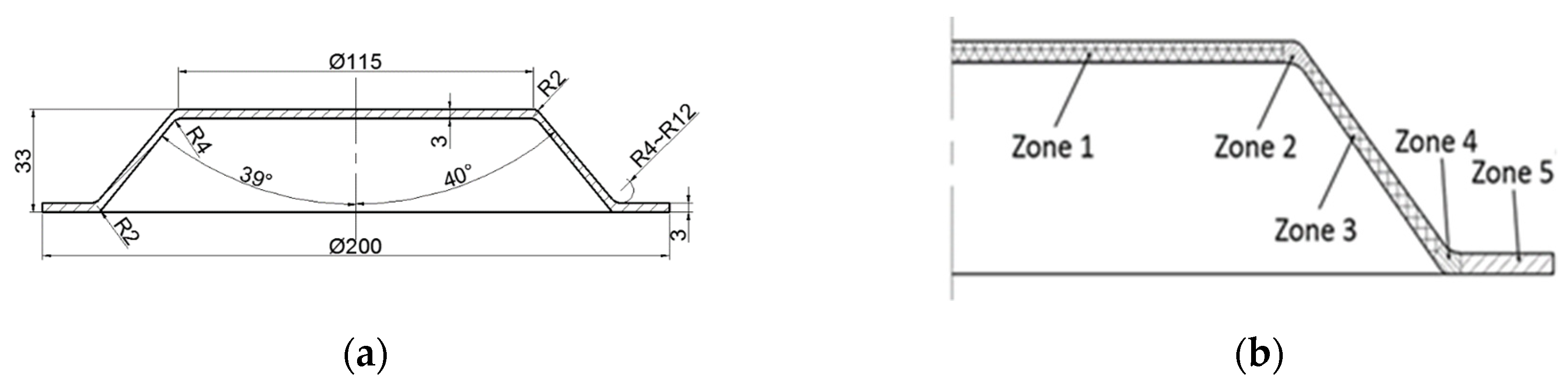
2.2. Establishment of 3D Finite Element Model (FEM)

The target-forming structure of the variable section thin-walled conical spinning part is depicted in Figure 1a. For convenience of analysis, the workpiece is divided into five areas after formation, as illustrated in Figure 1b. Zone 1 is the flat top area of the workpiece, coming into contact with the tailstock instead of the roller. Zone 2 is the small end transition Zone, where the roller starts to come into contact with the workpiece. Zone 3 is the cone Zone, Zone 4 is the big end transition Zone and Zone 5 is the flange Zone. The wall thicknesses of conical parts on different diameters all vary. As depicted in Figure 2, the FEM consists of five parts: blank, mandrel, tailstock, roller 1 and roller 2. Firstly, the three-dimensional models of five parts have been established through a Pro/Engineer modeling software, and the assembly work is completed. Then, the five three-dimensional models have been imported into the DEFORM-3D software (Columbus, OH, USA). The blank is fixed on the top of the mandrel through the tailstock. The mandrel and tailstock rotate at a constant speed and cause the blank to rotate. The rollers on both sides feed according to the designed path, exert pressure on the blank and rotate passively. In this paper, the blank is a circular sheet with a thickness of 2 mm and a diameter of 200 mm. The blank is defined as an elastoplastic material. The mesh type is tetrahedral mesh and the number of meshes is 60,000. The mandrel, the tailstock and the rollers are defined as rigid bodies. The initial temperature of the tailstock and rollers was set at 20 ℃, the initial temperature of the mandrel was set at 500 ℃, and the initial temperature of the blank was set according to the experimental design. The thermal conductance was 2.5 × 10⁴ W∙m−2∙k−1, the number of simulation steps was 1000 with a friction coefficient of 0.12.

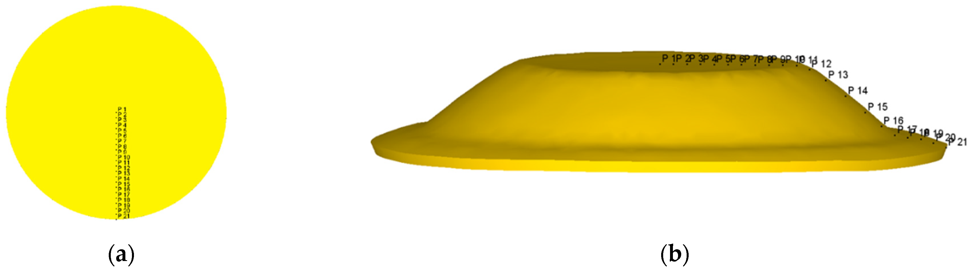
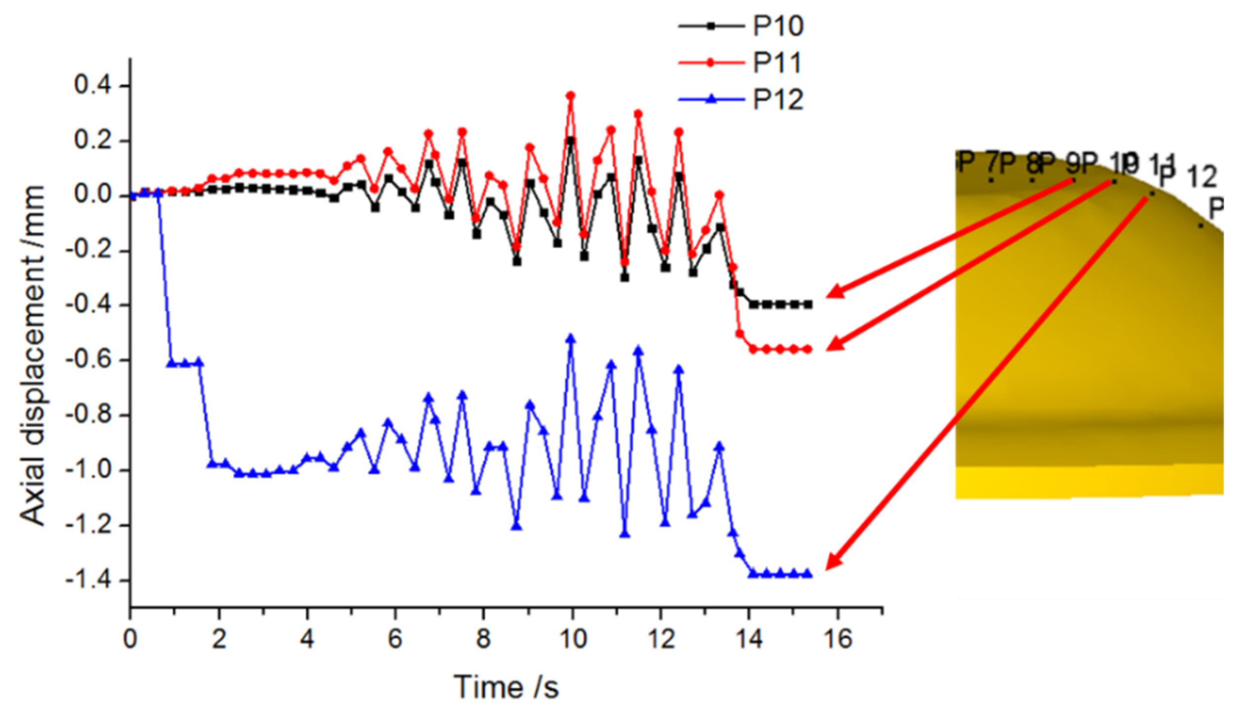
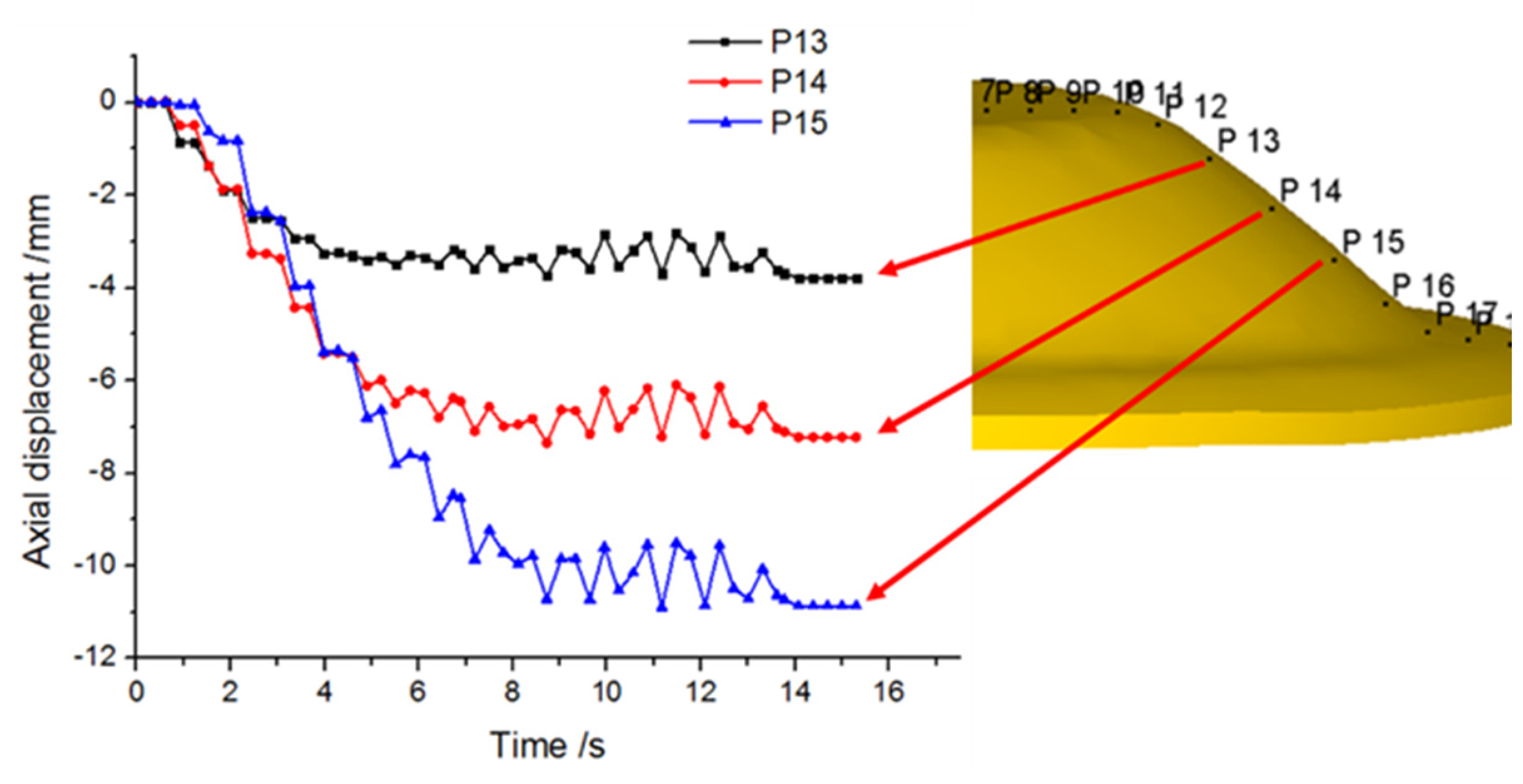
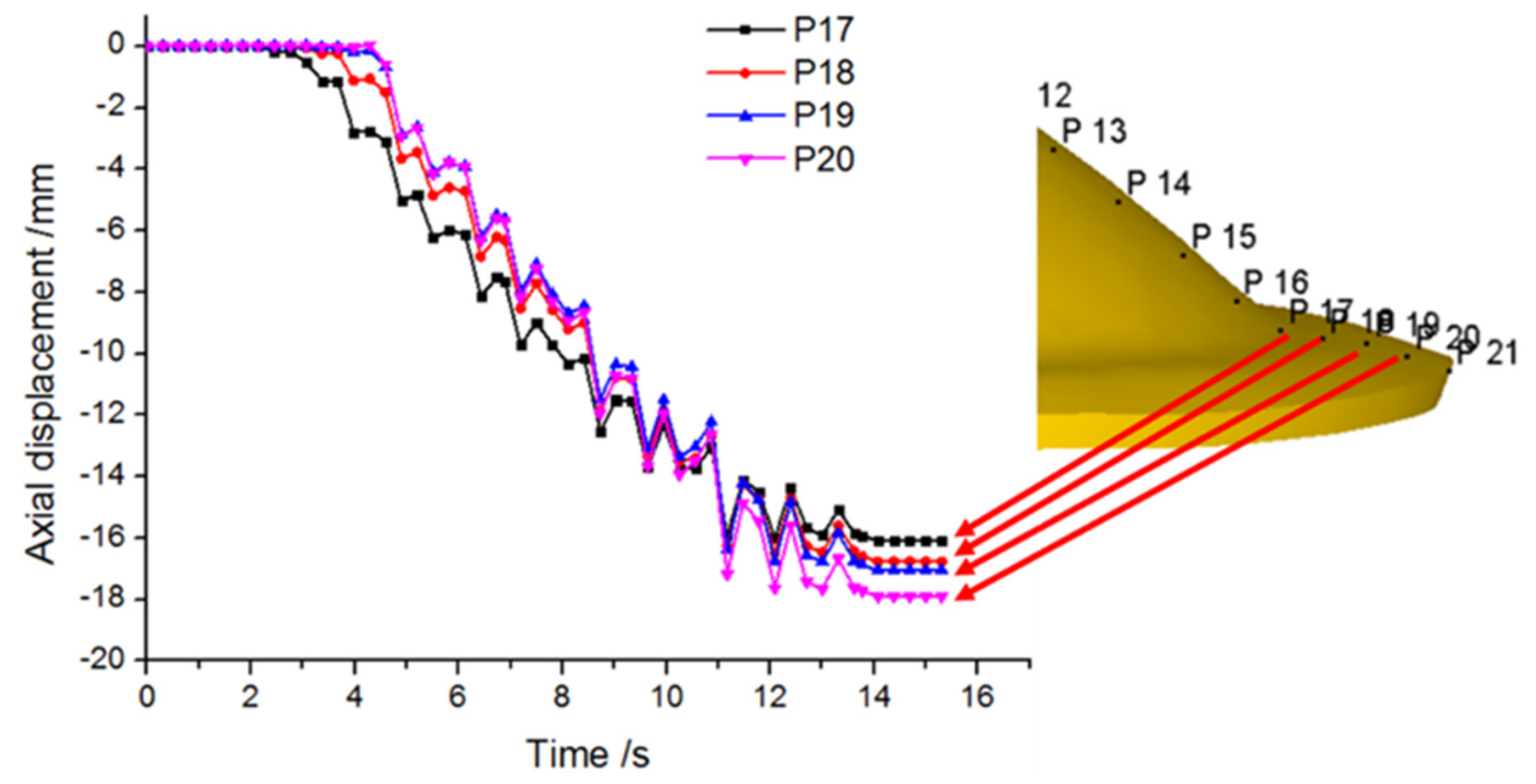
2.3. Finite Element Analysis of Material Flow Law

The workpiece is under the tangential, axis and radial force of the roller during spinning, and the stress situation is more complex. However, the thin-walled conical part is mainly affected by axial tension. In this paper, the point tracking method was used to compare the axial displacement before and after the formation of the tracking point. The position change of each point and the material flow law of variable-section thin-walled conical parts could be observed. A set of simulation results were selected for analysis. The simulation parameters were as follows: the initial temperature of the blank was 1000 ℃, the radius of the roller nose was 6 mm, the feed ratio of the roller was 0.4 mm/r, and the mandrel rotation rate was 300 rpm. A total of 21 points were selected at equidistant intervals along the direction of the blank radius, and the position changes of these points prior to and following the formation were analyzed. The point selection is illustrated in Figure 3.
The sampling points P1 to P9 are located in Zone 1, and there is almost no change in the axial position during the hot spinning process. The metal in Zone 2 flows along the circular arc of the mandrel fillet. As depicted in Figure 4, the axial position of sampling point P10 remains unchanged at first, and P10 moves downward in a fluctuating manner as the roller moves along the mandrel. The reason for the fluctuation is that P10 is squeezed upward by the roller when the roller is close to the sampling point. When the roller is distant from the sampling point, P10 is stretched by the outer metal, and causes a downward movement of the axial position. The axial position of sampling point P11 first moves upward and then moves downward in a fluctuating manner, and the moving mechanism is identical to that of P10. The axial position of sampling point P12 decreases rapidly at first and then fluctuates. This fluctuation occurs because the sampling point 12 is in the contact area of Zone 2 and Zone 3. Due to the large thinning rate of the small end of cone and large metal deformation, the axial position of P12 rapidly decreases. After formation, the axial position of sampling points in Zone 2 remains unchanged.
The axial displacement distance of sampling points on the outer wall of Zone 3 is depicted in Figure 5. It can be inferred from the figure that Zone 3 is the cone area, which is the main deformation area of variable-section conical spun parts. The axial displacement of sampling points P13 to p15 is large. The axial position of each sampling point in Zone 3 first moves downwards and then remains unchanged. Moreover, the downward movement rate of each sampling point is identical, and the movement rate is equal to the feed rate of the roller. The zigzag shape of the curve in the figure is due to the springback deformation behavior of the spun part in the forming process, leading to the fluctuation of the axial position of each sampling point in Zone 3. Secondly, because the blank rotates along the axial direction, the different contact area of the roller leads to the interaction between the roller extrusion and the metal axial drawing, which also accounts for the serrated fluctuation of the curve.
The sampling point p17 is located in Zone 4, but its flow law is similar to that of Zone 5. It can be inferred from the Figure 6 that Zone 5 is the flange area. During the forming process, the change trend of axial movement of each sampling point in this area is almost identical, and the axial displacement rate is almost identical to the feed rate of the roller, indicating that the metal flow law of each sampling point in the flange area is basically the same. At the end of forming, the axial displacement distance of the sampling point on the outer end of the flange is larger than that on the inner side of the flange, indicating the downwards bending and uneven appearance of the flange part.

3. Effects of Process Parameters on Surface Straightness

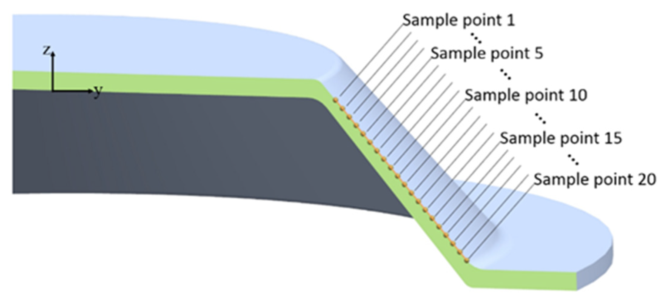
3.1. Single Factor Experiment Design

For intuitive and quick analysis of the influence of process parameters on variable-section conical spun parts, a single factor variable experiment design is used in this paper. Through the FEM model, the effects of spinning temperature Tc, mandrel rotation rate n and roller feed ratio f on the straightness of the outer surface of variable-section conical spun parts have been studied. The test plan is depicted in Table 4. According to the simulation results, the positions of sampling points have been collected, as shown in Figure 7, and Figure 8, Figure 9 and Figure 10 are obtained, which are the contour curves of the cone surface under process parameters.

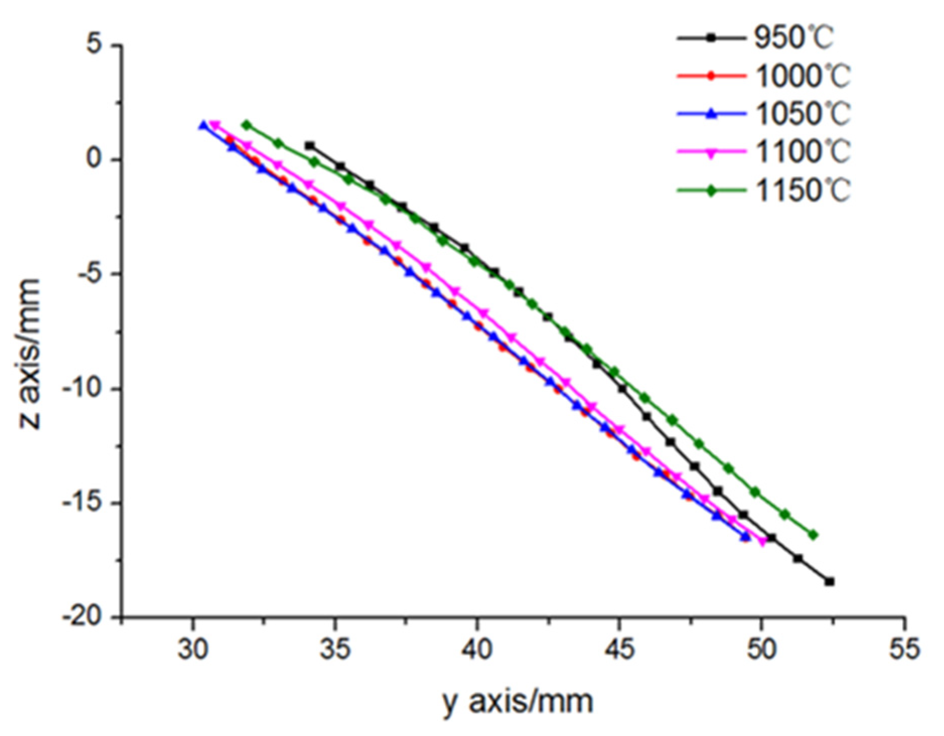
3.1.1. Effect of Spinning Temperature on Surface Straightness

It can be inferred from Figure 8 that with the increase of spinning temperature, the straightness of the cone outer surface first increases and then decreases. When the temperature increases from 950 °C to 1000 °C, the straightness of the cone surface increases. When spinning the small end of the cone, because of the large thinning rate, large metal deformation, and low temperature, the required spinning force is large, affecting the straightness of the cone surface. Moreover, due to poor metal fluidity, the metal easily appears in the middle of the cone. When spinning the big end of the cone, the thinning rate becomes smaller, the metal flow distribution is uniform, and the outer surface of the cone keeps a satisfactory straightness. When the temperature increases from 1000 °C to 1100 °C, the outer surface of the cone keeps good straightness. When the temperature is increased from 1100 °C to 1150 °C, the straightness decreases. As the temperature is too high, the fluidity of the surface metal increases, and it easily flows along the circumferential direction in the process of roller extrusion. To sum up, 1000 °C to 1100 °C is the optimum range to ensure the cone surface.

3.1.2. Effect of Mandrel Rotation Rate on Surface Straightness

It can be inferred from Figure 9 that the straightness of the upper part of the cone is subpar, and because the large thinning rate in the small end of the variable-section conical spun part, the metal in front of the roller is significantly stressed, and the metal flow is blocked, giving rise to the phenomenon of stacking, which consequently affects the straightness of the outer surface of the cone. It can be intuitively seen from the figure that when the mandrel speed increases from 180 to 420 r/min, the straightness of the outer surface of the cone gradually increases. This is because with an increase of the mandrel speed, the speed of the roller relative to the workpiece is larger under the same feed rate of the roller, the metal flow is less hindered by the roller, and the metal fluidity is satisfactory, so the phenomenon of metal stacking is essentially prevented. The straightness of the conical surface can be improved by increasing the rotating speed. Therefore, when the mandrel speed is 420 r/min, the straightness of the cone outer surface is ideal.

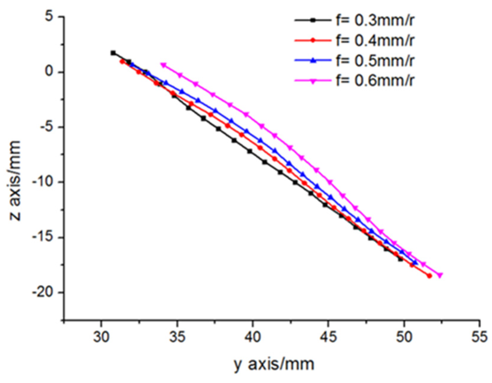
3.1.3. Effect of Roller Feed Ratio on Surface Straightness

It can be seen from Figure 10 that the middle of the cone often bulges. This is because in the early stage of spinning forming, due to the large thinning rate of the small end of the cone and the large amount of metal deformation, a large amount of metal flows to the unprocessed area of the part, giving rise to the metal bulge in the middle of the cone. When the feed ratio increases from 0.3 to 0.6 mm/r, the straightness of the cone decreases with the increase of the feed ratio. This is because the movement of the roller relative to the blank increases, the deformation rate of the metal accelerates, and the surface metal flows easily along the circumferential direction with uneven distribution. When the feed ratio is 0.3 mm/r, the straightness of the outer surface of the cone is optimum.

3.2. Design and Analysis of Orthogonal Experiment

In this paper, straightness tolerance is used to reflect the straightness of variable-section conical spun parts. The calculation method is illustrated in Figure 7 and Equations (2)–(4). A total of 20 sampling points are selected along the axial equal distance of the cone after spinning, and these points are on the axisymmetric plane of the part. The smaller the ΔY is, the better the straightness is.
Δ Y k = y k y
Δ Y a = Δ Y k sin θ
Δ Y = max Δ Y a min Δ Y a
where y k is the actual coordinate value of the Y-axis of sampling point, k = 1~20; y is theoretical coordinate value of the sampling point; Δ Y k is the position deviation of the sampling point in a Y-axis direction; θ is the angle between the theoretical contour of the cone and the horizontal plane; Δ Y a is the vertical distance from the sampling point to the theoretical contour of the cone; Δ Y is straightness tolerance.
An orthogonal experimental design is an experimental design method to study multi-factor and multi-level features. It has the advantages of high efficiency, rapidity and low costs. In the spinning process, numerous process parameters affect the forming quality. The main process parameters studied in this orthogonal experiment are spinning temperature Tc, roller nose radius r, mandrel rotation rate n, and roller feed ratio f. In this paper, a four-factor and four-level orthogonal experiment was designed by finite element simulation with straightness tolerance as the response variable. To avoid repeated experiments, an empty column was set in the table. The orthogonal experiment scheme and experiment results are listed in Table 5.
A variance analysis on the straightness tolerance was carried out in Table 5 to get the range analysis table of straightness, as listed in Table 6. R is the range, and the larger the R value is, the greater the effect of this factor on the test index is, and the more substantial it is. Therefore, the effect order of various factors on the straightness of cone surface is ABCD, that is, spinning temperature has the greatest influence on the straightness, followed by the roller nose radius, then the mandrel rotation rate. The roller feed ratio has the least influence on the straightness. The optimal level of the factors can be judged by the size of T. The test index is the straightness tolerance of the outer surface of the cone. The smaller the T value, the higher the straightness of the outer surface of the cone. The best combination of A, B, C and D is A2B1C2D1. Under this process combination, the outer surface straightness of GH4169 superalloy conical spun parts are ideal. The optimal process parameters of this group are numbered as 17, and the simulation of the 17th group was carried out. Its straightness tolerance was 0.155 mm. From the 16 groups of simulation results in Table 5, it can be inferred that in the orthogonal experiment plan, the maximum straightness tolerance of the cone outer surface was 1.723 mm, and the minimum was 0.225 mm, while in the 17th optimal combination, the straightness tolerance of the cone outer surface did not exceed 70% of the minimum value in Table 5. The optimization result is satisfactory, and the optimal combination of process parameters has reference significance.

4. Spinning Experiment and Analysis

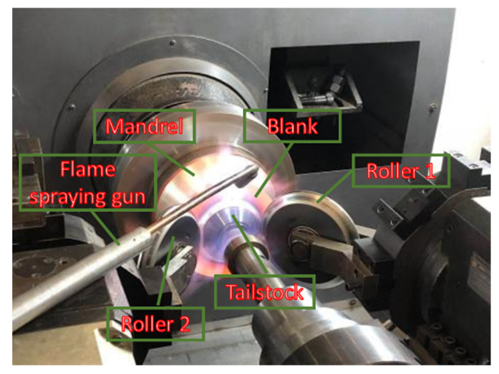
4.1. Spinning Experiment

A total of 17 groups of process parameters were used in the spinning experiment. The process parameters such as the mandrel rotation rate and the feed ratio of the roller were set. During the forming process, the flame spray gun was used to heat the blank and the mandrel until the temperature of the blank met the requirements of the experimental design. After formation, the workpieces were cooled at room temperature. Experimental process are illustrated in Figure 11 and Figure 12, which show the spun parts. The right side of the figure shows the simulation of the 17th group of optimal parameter combination. Compared to the spinning experimental parts, it can be found that the finite element simulation results are highly consistent with the experimental results, with an excellent forming effect.

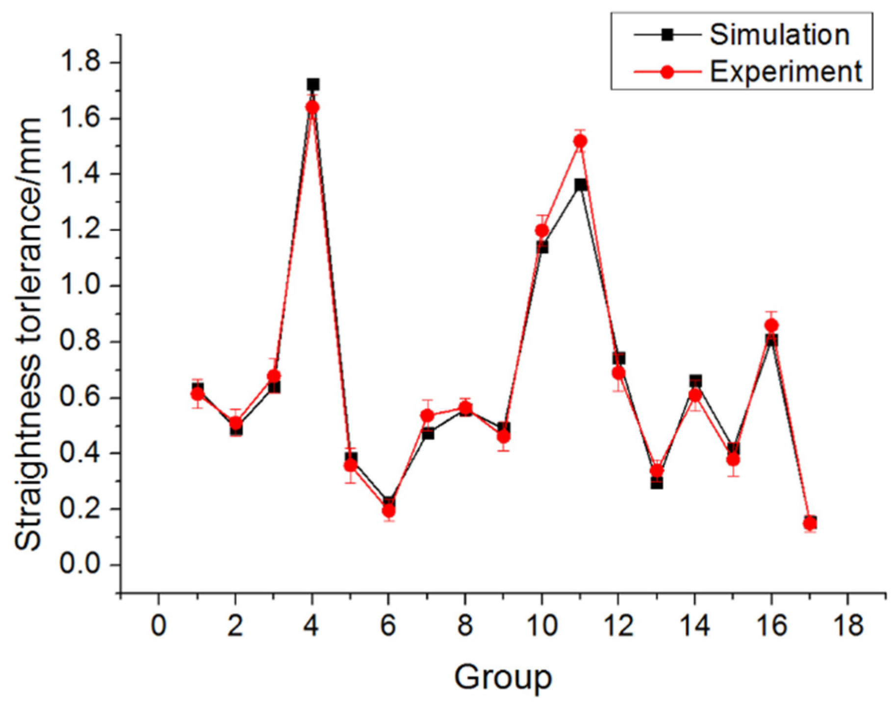
4.2. Comparison Analysis

To yield comparative data, the distribution of the sampling points on the workpiece is consistent with that of the post-processing of the finite element simulation software, and then the coordinate values of these marked sampling points were measured by a ZEISS MMZ-B203015 coordinate measuring machine (CMM). Its length measurement error is 4.5+L/300 (ISO10360-2:2009). The measuring process of CMM is illustrated in Figure 13. The straightness of the outer surface of the cone of 17 groups of experimental pieces was obtained by measurement and calculation. The data curve of the comparison between the experimental results and the simulation results is depicted in Figure 14.
It can be concluded from Figure 14 that the experimental results and simulation reuslts of the straightness tolerance of the cone outer surface possess the same change trend, with a small numerical error whereby the maximum error occurred in group 11. The experimental result of the straightness tolerance of the cone outer surface was 1.52 mm, and the simulation result was 1.37 mm, with an error within 10%; the minimum error occurred in group 17. The experimental result of the straightness tolerance of the cone outer surface was 0.155 mm, the simulation result was 0.15 mm, and the minimum error was 3%. The error of straightness tolerance between finite element simulation and spinning experiment was between 3–10%. The comparative analysis of simulation and experimental data demonstrates that the optimal combination of process parameters for the straightness of the cone outer surface has reference significance. The results of spinning experiments verify the reliability of the simulation of power spinning of variable-section conical spun parts.

5. Conclusions

The analysis of material flow law of variable-section conical spun parts proves that the metal does not move axially in the flat top area of the workpiece, and the axial displacement in the transition fillet area of the small end of the cone is small. Moreover, the metal axial displacement in the cone area is large, and the axial displacement rate is identical to the roller feed ratio. At the end of forming, the metal in each region of the workpiece does not exhibit plastic flow, and the axial position remains unaltered.
The straightness of cone surface increases with the increase of roller rotation rate, but decreases with the increase of feed ratio. With the increase of spinning temperature, the straightness of the cone surface first increases and then decreases. In the process-parameters studied, the spinning temperature has the greatest influence on the surface straightness, followed by the roller nose radius and the mandrel rotation rate. The feed ratio has the least influence on the surface straightness.
In this study, the optimal combination of process parameters is a spinning temperature of 1000 ℃, a roller nose radius of 4 mm, a mandrel speed at 300 r/min and a roller feed ratio of 0.3 mm/r. Under the optimal combination of process parameters, the tolerance between finite element simulation and experimental results is less than 5%, which demonstrates the reliability of the finite element simulation results. The combination of finite element simulation and statistical analysis can substantially improve the forming quality of variable-section conical spun parts.

Author Contributions

Conceptualization, Y.L. and Z.C.; methodology, Y.L. and X.S.; formal analysis, Y.L. and Z.C.; investigation, Y.L., Z.C. and X.S.; writing-original draft preparation, Y.L.; writing-review and editing, Z.L., X.S., Z.C. and B.Y.; visualization, Y.L., X.S., Z.C., Z.L. and B.Y.; project administration, X.S. All authors have read and agreed to the published version of the manuscript.

Funding

This research was supported by the National Natural Science Foundation of China (NSFC) (No: 51975301); Ningbo Science and Technology Innovation 2025 Major Special Project (No: 2020Z110).

Acknowledgments

The authors gratefully acknowledge the Zhejiang Provincial Key Lab of Part Rolling Technology in Ningbo University, China.

Conflicts of Interest

The author declares no conflict of interest.

References

  1. Wong, C.; Dean, T.; Lin, J. A review of spinning, shear forming and flow forming processes. Int. J. Mach. Tools Manuf. 2003, 43, 1419–1435. [Google Scholar] [CrossRef]
  2. Music, O.; Allwood, J.; Kawai, K.-I. A review of the mechanics of metal spinning. J. Mater. Process. Technol. 2010, 210, 3–23. [Google Scholar] [CrossRef]
  3. Xia, Q.; Xiao, G.; Long, H.; Cheng, X.; Sheng, X. A review of process advancement of novel metal spinning. Int. J. Mach. Tools Manuf. 2014, 85, 100–121. [Google Scholar] [CrossRef]
  4. Zhan, M.; Yang, H.; Guo, J.; Wang, X.-X. Review on hot spinning for difficult-to-deform lightweight metals. Trans. Nonferrous Met. Soc. China 2015, 25, 1732–1743. [Google Scholar] [CrossRef]
  5. Jahazi, M.; Ebrahimi, G. The influence of flow-forming parameters and microstructure on the quality of a D6ac steel. J. Mater. Process. Technol. 2000, 103, 362–366. [Google Scholar] [CrossRef]
  6. Xia, Q.-X.; Long, J.-C.; Zhu, N.-Y.; Xiao, G.-F. Research on the microstructure evolution of Ni-based superalloy cylindrical parts during hot power spinning. Adv. Manuf. 2019, 7, 52–63. [Google Scholar] [CrossRef]
  7. Xiao, G.; Xia, Q.; Long, J.; Chen, W. Research on the forming quality and mechanical properties of cylindrical spun parts with ultrafine-grained structure during power spinning. Int. J. Adv. Manuf. Technol. 2018, 97, 2979–2986. [Google Scholar] [CrossRef]
  8. Li, Z.-X.; Shu, X.-D. Numerical and experimental analysis on multi-pass conventional spinning of the cylindrical part with GH3030. Int. J. Adv. Manuf. Technol. 2019, 103, 2893–2901. [Google Scholar] [CrossRef]
  9. Essa, K.; Hartley, P. Numerical simulation of single and dual pass conventional spinning processes. Int. J. Mater. Form. 2009, 2, 271–281. [Google Scholar] [CrossRef]
  10. Essa, K.; Hartley, P. Optimization of conventional spinning process parameters by means of numerical simulation and statistical analysis. Proc. Inst. Mech. Eng. Part B J. Eng. Manuf. 2010, 224, 1691–1705. [Google Scholar] [CrossRef] [Green Version]
  11. Song, X.; Fong, K.S.; Oon, S.R.; Tiong, W.R.; Li, P.F.; Korsunsky, A.M.; Danno, A. Diametrical growth in the forward flow forming process: Simulation, validation, and prediction. Int. J. Adv. Manuf. Technol. 2013, 71, 207–217. [Google Scholar] [CrossRef]
  12. Kuss, M.; Buchmayr, B. Analytical, numerical and experimental investigations of a ball spinning expansion process. J. Mater. Process. Technol. 2015, 224, 213–221. [Google Scholar] [CrossRef]
  13. Xu, W.; Zhao, X.; Ma, H.; Shan, D.; Lin, H. Influence of roller distribution modes on spinning force during tube spinning. Int. J. Mech. Sci. 2016, 113, 10–25. [Google Scholar] [CrossRef]
  14. Wang, X.-K.; Xia, Q.-X.; Cheng, X.-Q. Deformation behavior of haynes230 superalloy during backward flow forming. Int. J. Precis. Eng. Manuf. 2017, 18, 77–83. [Google Scholar] [CrossRef]
  15. Fazeli, A.R.; Ghoreishi, M. Investigation of effective parameters on surface roughness in thermomechanical tube spinning process. Int. J. Mater. Form. 2009, 2, 261–270. [Google Scholar] [CrossRef]
  16. Wang, L.; Long, H. A study of effects of roller path profiles on tool forces and part wall thickness variation in conventional metal spinning. J. Mater. Process. Technol. 2011, 211, 2140–2151. [Google Scholar] [CrossRef]
  17. Wang, L.; Long, H. Investigation of material deformation in multi-pass conventional metal spinning. Mater. Des. 2011, 32, 2891–2899. [Google Scholar] [CrossRef]
  18. Rentsch, B.; Manopulo, N.; Hora, P. Numerical modelling, validation and analysis of multi-pass sheet metal spinning processes. Int. J. Mater. Form. 2016, 10, 641–651. [Google Scholar] [CrossRef]
  19. Gan, T.; Yu, Z.-Q.; Zhao, Y.-X.; Evsyukov, S.; Lai, X.-M. Effects of backward path parameters on formability in conventional spinning of aluminum hemispherical parts. Trans. Nonferrous Met. Soc. China 2018, 28, 328–339. [Google Scholar] [CrossRef]
  20. Zhang, H.-R.; Zhan, M.; Guo, J.; Wang, X.-X.; Gao, P.; Ma, F. Forming the transverse inner rib of a curved generatrix part through power spinning. Adv. Manuf. 2019, 7, 105–115. [Google Scholar] [CrossRef]
  21. Wang, L.; Long, H.; Ashley, D.; Roberts, M.; White, P. Effects of the roller feed ratio on wrinkling failure in conventional spinning of a cylindrical cup. Proc. Inst. Mech. Eng. Part B J. Eng. Manuf. 2011, 225, 1991–2006. [Google Scholar] [CrossRef]
  22. Watson, M.; Long, H.; Lu, B. Investigation of wrinkling failure mechanics in metal spinning by Box-Behnken design of ex-periments using finite element method. Int. J. Adv. Manuf. Technol. 2015, 78, 981–995. [Google Scholar] [CrossRef] [Green Version]
  23. Chen, S.; Gao, P.; Zhan, M.; Ma, F.; Zhang, H.; Xu, R. Determination of formability considering wrinkling defect in first-pass conventional spinning with linear roller path. J. Mater. Process. Technol. 2019, 265, 44–55. [Google Scholar] [CrossRef]
  24. Mohebbi, M.S.; Pour, M.R. Effects of temperature, initial conditions, and roller path on hot spinnability of AZ31 alloy. Int. J. Adv. Manuf. Technol. 2019, 103, 377–388. [Google Scholar] [CrossRef]
  25. Ma, J.; Shen, J.L.; Li, M.M.; Liang, Y. Effect of chemical composition on microstructure and mechanical properties of GH4169 alloy. Heat Treat. Met. 2020, 45, 197–204. [Google Scholar]
  26. Wang, H.Y.; Zhao, W.; Dong, J.X.; Zhang, M.C.; Yao, Z.H. Research on optimization of GH4169 turbine disc hot die forging technique based on Deform-3D and orthogonal experimental method. Forg. Stamp. Technol. 2013, 38, 13–19. [Google Scholar]
Figure 1. Structure of target part: (a) Part sectional drawing; (b) Part partition.
Applsci 11 08187 g001
Figure 2. The finite element model of spinning.
Applsci 11 08187 g002
Figure 3. The location of material flow law analysis points: (a) Before part forming; (b) after part forming.
Applsci 11 08187 g003
Figure 4. Axial displacement of sampling point in Zone 2.
Applsci 11 08187 g004
Figure 5. Axial displacement of the sampling point in Zone 3.
Applsci 11 08187 g005
Figure 6. Axial displacement of the sampling point in Zone 4 and 5.
Applsci 11 08187 g006
Figure 7. Distribution of sampling points for straightness calculation.
Applsci 11 08187 g007
Figure 8. Effect of temperature on straightness.
Applsci 11 08187 g008
Figure 9. Effect of mandrel rotation rate on straightness.
Applsci 11 08187 g009
Figure 10. Effect of roller feed ratio on straightness.
Applsci 11 08187 g010
Figure 11. Spinning process.
Applsci 11 08187 g011
Figure 12. Experiment and simulation parts.
Applsci 11 08187 g012
Figure 13. Coordinate measurement.
Applsci 11 08187 g013
Figure 14. Comparison of experimental and simulation results of straightness tolerance.
Applsci 11 08187 g014
Table 1. GH4169 alloy composition (wt. %).
CSiMnCrBAlMoFeTiNbNi
0.050.300.2019.00.0060.53.018.01.05.3others
Table 2. GH4169 alloy elastic modulus.
T (℃)20100200300400500600700
E (GPa)205201196189183176169164
Table 3. GH4169 alloy Poisson′s ratio.
T (℃)20100200300400500600700
μ0.30.30.30.30.310.310.320.34
Table 4. Single factor experimental design.
NoTemperature TC/℃Mandrel Rotation Rate n/rpmRoller Feed Ratio f/mm∙r−1
110501800.6
210502400.6
310503000.6
410503600.6
510504200.6
610503000.3
710503000.4
810503000.5
99503000.6
1010003000.6
1111003000.6
1211503000.6
Table 5. Orthogonal experimental design and results.
NoSpinning Temperature Tc (℃)Roller Nose Radius R (mm)Mandrel Rotation Rate n (r/min)Roller Feed Ratio f (mm/r)Null ColumnsStraightness Tolerance ΔY (mm)
ABCD
11 (950)1 (4)1 (240)1 (0.3)10.634
212 (6)2 (300)2 (0.4)20.491
313 (8)3 (360)3 (0.5)30.641
414 (10)4 (420)4 (0.6)41.723
52 (1000)12340.384
6221430.225
7234120.474
8243210.559
93 (1050)13420.490
10324311.140
11331241.365
12342130.745
134 (1100)14230.296
14423140.662
15432410.419
16441320.809
Table 6. Straightness tolerance range analysis table.
FactorABCD
T13.4891.8043.0332.515
T21.6422.5182.0392.711
T33.7402.8992.3522.974
T42.1863.8363.6332.857
t10.8720.4510.7580.629
t20.4110.6300.5100.678
t30.9350.7250.5880.744
t40.5470.9590.9080.714
Level2121
R2.0982.0321.5940.459
OrderABCD
Publisher’s Note: MDPI stays neutral with regard to jurisdictional claims in published maps and institutional affiliations.

