Abstract
Field investigation shows that most corrugations occur on the inner rail surface of curved tracks with a radius of less than 700 m. In order to explore the formation mechanism of metro corrugation, the relationship between wheel–rail stick–slip characteristics and rail corrugation is studied by combining single wheelset curving and a rigid–flexible coupling model. The numerical results illustrate that the lateral torsional stick–slip vibration of inner rail–inner wheel of the guiding wheelset on the small radius curve eventually leads to the generation of inner rail corrugation, and the lateral torsional stick–slip vibration of outer rail–outer wheel of the driven wheelset may also occur, but the intensity is weak and the probability is low. The lateral torsional stick–slip vibration of inner rail–inner wheel of the guiding wheelset on the large radius curve is also easy to cause inner rail corrugation, but the degree of inner rail corrugation is lower than that on the small radius curve; the outer rail on the large radius curve is still not easy to produce corrugation. The formation mechanism of rail corrugation on the straight track is different from that on the curve track, which is mainly related to the wheel–rail longitudinal torsional stick–slip vibration.
1. Introduction
Rail corrugation is a kind of periodic wavy wear, which frequently occurs on the running surface of a rail. Corrugation will not only excite the high-frequency dynamic load of the wheel and rail, leading to the deterioration of vehicle and track components, but also produces high-level noise and vibration, affecting the living environment of residents along the line. Rail corrugation has always been one of the urgent problems to be solved in the railway industry. If the corrugation phenomenon can be avoided without treatment, it can save a lot of human and material resources [1,2,3,4]. For more than 100 years, railway researchers have carried out a large number of experiments and simulation studies on rail corrugation, and put forward many theories to explain it. Most of them attribute the causes of rail corrugation to the resonance of the vehicle–track system (such as the resonance of the wheel–rail dynamic force P2 [5,6,7,8], bending/torsion resonance of the wheelset [9,10,11], the pinned–pinned resonance of track structure [12,13,14], etc.), or the unstable self-excited vibration of wheel–rail system [15,16,17,18].
To date, rail corrugation is still an active research field. In 2009, based on the literature investigation, Grassie [19] corrected rail corrugation to a frequency-fixed phenomenon and divided rail corrugation into the following six types: roaring rails, rutting, other P2 resonance, heavy haul, light rail, and trackform-specific. Chen et al. [20,21,22,23] considered that the friction self-excited vibration of wheel–rail system was the cause of rail corrugation under the condition of creep force saturation, and systematically studied the influencing parameters of rail corrugation. By analyzing the correlation between the passing frequency of rail corrugation and the natural frequency of the track, Li et al. [24] concluded that the natural vibration characteristics of the track structure and vehicle passing speed were the key reasons for the occurrence of rail corrugation. Wang et al. [9] studied the causes of rail corrugation in the small radius curve section with Cologne egg fasteners using field tests and numerical simulations; they found that the lateral vibration of the rail caused by the lateral mode of the wheelset was one of the causes in this section. Based on the vehicle–floating slab track coupling model, Zheng et al. [25] proposed the limit value of rail corrugation of metro floating slab track from the aspects of vehicle operation safety, stability, and vehicle-track dynamic interaction. Through field investigation, test, and numerical analysis, Li et al. [26] found that the rail corrugation of Cologne egg fastener track was related to the vertical bending vibration of the track structure, and the values of fastener stiffness and damping had a great influence on the rail corrugation. Zhang et al. [27] investigated the phenomenon of wavelength-fixed corrugation on the shear-type damping fastener track, and the results indicated that the phenomenon is related to the vertical dynamic responses of rail under the specific track form. Li et al. [28] established a three-dimensional finite element model with dynamic friction rolling contact, analyzed the system responses of track structure vibration mode, wheel–rail contact force, and rail wear, and obtained that the longitudinal vibration mode of track structure may be the dominant factor leading to the formation of short pitch corrugation.
Vibration is the macroscopic manifestation of the vehicle–track system. As rail corrugation occurs in the wheel–rail contact zone, it is closely related to the wear of rail material. Therefore, it is more convincing to study the microscopic wheel–rail contact behaviors to reveal the formation mechanism of rail corrugation. For metro lines, rail corrugation mostly occurs in the small radius curve sections, and the corrugation of the inner rail is more serious than that of outer rail [29,30]. Meantime, abnormal rail corrugation with a short recurrence period also occurs in some large radius curves and straight sections [31,32,33]. Based on this, from the perspective of microscopic wheel–rail stick–slip properties, this paper analyzes the generation mechanism of rail corrugation phenomenon commonly occurring on the metro line, including curve and straight track sections. Firstly, according to the field investigation, the occurrence situation of rail corrugation on Tianjin Metro Line 6 was analyzed. Then, by analyzing the curve passing form of a single wheelset, the cause of rail corrugation was explained from the wheel–rail contact stick–slip theory. Finally, using the method of multibody dynamics, the vehicle–track space rigid–flexible coupling model was constructed to study the relationship between wheel–rail stick–slip characteristics and rail corrugation, and the proposed wheel–rail contact stick–slip theory was verified. Compared with the existing literature, the difference of this paper is that the cause of rail corrugation on metro lines is explored from the microscopic level of wheel–rail stick–slip behaviors, and the developed theory can well explain the rail corrugation phenomenon on curves and straight lines.
2. Statistics of Measured Corrugation on Metro Lines
The measured line was located in the Tianjin Metro Line 6. The north section of the line was opened to traffic in December 2016, and the south section was opened to traffic in April 2018. The train adopts 6B marshaling, and the maximum design speed was 80 km/h. The design situations of line and track are shown in Table 1.

Table 1.
Line and track design situations.
By measuring in the Tianjin Metro Line 6, the corresponding corrugation state of the line can be obtained, as shown in Table 2. It can be seen that most of the corrugations occur on the track with a curve radius of less than 700 m. In addition, rail corrugation also occurs in a 500 m long straight section. Furthermore, combined with the field investigation, it is found that rail corrugation mainly occurs on the inner rail surface, and there is also corrugation on some sections of the outer rail, but the occurrence range is relatively small. The field pictures of rail corrugation are shown in Figure 1.
Table 2.
Field measurement results of Tianjin Metro Line 6.
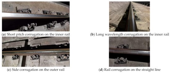
Figure 1.
Corrugation pictures on-site. (a) Short pitch corrugation on the inner rail. (b) Long wavelength corrugation on the inner rail. (c) Side corrugation on the outer rail. (d) Rail corrugation on the straight line.
For the convenience of comparison, the wave depth amplitudes of rail corrugation corresponding to tracks with different curve radii are plotted in Figure 2. It can be concluded that 75% of rail corrugations occur in curve tracks with a radius less than 400 m, and the wave depth amplitudes are relatively large. At the same time, it can be seen from Figure 2 that rail corrugations with amplitudes greater than 0.4 mm only exist on curve tracks with radii of 300–400 m, which indicates that the rail corrugation will be more serious with the decrease of curve radius. In order to explain the serious corrugation phenomenon of small radius curves, the cause of rail corrugation was explored from the wheel–rail contact stick–slip theory by analyzing the curve passing form of a single wheelset.
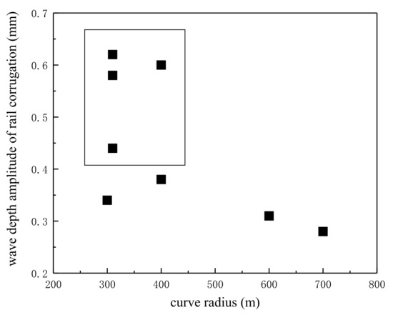
Figure 2.
Amplitude distribution diagram of rail corrugation.
3. Theoretical Analysis on the Cause of Rail Corrugation
When the vehicle is running along the line, in order to avoid the frequent contact between the wheel flange and the rail side and facilitate the vehicle to pass through the curve, the outside distance between the left and right wheel flanges is less than the track gauge, so the wheelset can make lateral displacement and yaw angle relative to the track. Under conditions of different lateral displacements and yaw angles, the contact points between the left and right wheels and rails have different positions, so the contact parameters between wheel and rail also change accordingly, that is, the geometric parameters of wheel–rail contact are actually functions of lateral displacement and yaw angle of the wheelset relative to the track. Assuming the wheel has LM wear-type tread and the rail has standard CHN60 profile, when the center of the wheelset is consistent with the center line of the track, the contact angles between the left and right wheels and rails are all , and the rolling circle radii of wheels are all . When the lateral displacement occurs to the right of the wheelset, the diagram of the wheel–rail motion relationship is shown in Figure 3, and the contact angles of the left and right wheels and rails are as follows:
where, is the left wheel–rail contact angle; is the right wheel–rail contact angle; is the half of rolling circle span of left and right wheels; is the contact angle parameter, representing the variation rate of the slope of contact surface with respect to the lateral displacement of the wheelset, which can be expressed as follows:
where, is the curvature radius of the wheel tread; is the curvature radius of the rail top surface.
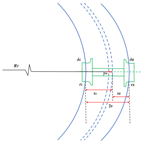
Figure 3.
Diagram of the wheel–rail motion relationship.
When the lateral displacement of the wheelset is , the distances between the wheelset center line and the wheel–rail contact points are as follows:
where, is the distance between the wheelset center line and the left wheel–rail contact point; is the distance between the wheelset center line and the right wheel–rail contact point; is the variation rate of the distance between the wheelset center line and the wheel–rail contact point with respect to the lateral displacement of the wheelset, which can be expressed as follows:
When the wheelset passes the circular curve line with a radian and a radius , the driving distances of the left and right wheels can be expressed as:
where, is the driving distance of the left wheel; is the driving distance of the right wheel. Furthermore, the driving distance difference between the left and right wheels is obtained as follows:
Because the wheelset can be approximately regarded as a rigid body, when the wheelset rotates around its center line, the rotation speed of each part is the same, and the larger the radius of the wheel rolling circle, the longer the running distance at the same angle. The greater the radius difference between the left and right wheels of the same wheelset, the greater the running distance difference between the left and right wheels. When the wheelset lateral displacement is , the rolling circle radii of the left and right wheels are:
where, is the rolling circle radius of the left wheel; is the rolling circle radius of the right wheel; is the equivalent slope, representing the variation rate of the rolling circle radius difference of the left and right wheels on the lateral displacement of the wheelset, and its expression is:
Assuming that when the wheelset passes through a circular curve with a radian , the rotation angle of wheelset around its center line is , then the running distances of the left and right wheels are obtained as follows:
where, is the running distance of the left wheel; is the running distance of the right wheel. Similarly, it can be further obtained that the running distance difference when the left and right wheels are rolling is:
Thus, it can be acquired that the driving distance difference between the left and right wheels on the rails when the rolling circle radius difference of the wheels is considered is:
When is greater than 0, it means that the running distance difference between the left and right wheels is not enough to offset the driving distance difference between the left and right wheels on the rails, so that the wheelset lateral displacement is further expanded to make up for the driving distance difference between the left and right wheels. When is equal to 0, it means that the running distance difference between the left and right wheels is equal to the driving distance difference between the left and right wheels on the rails, and the wheelset is in a pure rolling state. When is less than 0, it means that the running distance difference between the left and right wheels exceeds the driving distance difference between the left and right wheels on the rails, so that the wheelset lateral displacement tends to decrease, so as to realize the steady rolling of the wheelset through the curve.
Through the above analysis, it can be seen that when the wheelset passes through the curve, the contact motion relationship between the inner and outer wheels (in order to distinguish from the straight line, we used the inner and outer wheels instead of the left and right wheels) and rails has been in a continuously changing process. When the running distance difference between the inner and outer wheels is not equal to the driving distance difference between the inner and outer wheels on rails, the inner and outer wheels will receive the lateral force at wheel–rail contact points, and the rails will receive the reaction force at same positions. The existence of the above force creates the wheel and rail bear torque. When the accumulated torque increases to a certain value, the adhesion force of the wheel–rail interface is less than the torsional force generated by the torque at the contact position, the torque will be suddenly be released, and the adhesion state between the wheel tread and rail surface will change into a slip state, that is, the “stick–slip” effect between wheel and rail. This process is completed in a very short moment, and it starts over and over again, so as to realize the smooth passing of the wheelset through the curve. As long as there is slip between wheel and rail, the torque on the wheel and rail will be released rapidly, that is, as shown in the curves of b and c in Figure 4, the torsional force (i.e., creep force) will drop to the dynamic friction force (the dynamic friction force is less than the static friction force), at this time, the torsional force is less than the static friction force. If the torque is released completely, the torsional force will return to 0, and the wheel–rail interface will become sticky again. So repeatedly, the wheel makes a lateral torsional stick–slip vibration on the rail surface. When the wheel and rail stick together, the wear of the rail surface is small, that is, the wave peak of the corrugation is formed. When the wheel slips on the rail, the wear of the rail surface is large, that is, the wave trough of the corrugation is formed. At present, the ATO (automatic train operation) mode is basically adopted in the metro train operation, that is, the speed of a section is constant. Therefore, the reciprocating operation of the train will aggravate the development of wavelength-fixed wear. Over time, obvious wavy wear will form on the rail surface. For the straight line, the wheel–rail torsional stick–slip vibration process also exists, but the torsional vibration intensity is weak, the appearance probability is less, so the occurrence possibility of rail corrugation on the straight line is low. Rail corrugation is also found in the straight section during the field measurement, as shown in the eighth line section in Table 2. Because the driving distance difference between left and right wheels on the straight line is relatively small, the rail corrugation of the straight line may be related to the wheel–rail longitudinal torsional stick–slip vibration. In this section, the formation mechanism of rail corrugation is explained from the wheel–rail contact stick–slip theory. In the following, the multibody dynamics method will be used to analyze the relationship between the wheel–rail stick–slip characteristics and rail corrugation, and verify the above formation mechanism of rail corrugation.
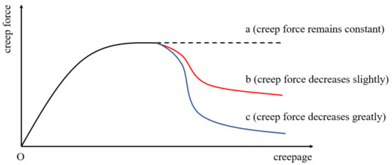
Figure 4.
Relation diagram between creep force and creepage.
4. Analysis of Wheel–Rail Stick–Slip Characteristics
By using the multibody dynamics method, the vehicle–track space rigid–flexible coupling model was established, and the relationship between the wheel–rail stick–slip characteristics and rail corrugation on different curvature radius lines was analyzed.
4.1. Vehicle–Track Space Rigid–Flexible Coupling Model
4.1.1. Establishment of Model
The space rigid–flexible coupling model mainly includes vehicle (motor car) model, track model, and wheel–rail contact models. The vehicle model is composed of body, bogies, and wheelsets. The body and bogie are treated with rigidity, the wheelset is regarded as a flexible body, and the wheel adopts an LM worn tread. The body, bogie, and wheelset all consider six degrees of freedom, namely, longitudinal movement, lateral movement, floating, rolling, nodding, and shaking, and the whole vehicle model has 42 degrees of freedom. The body and bogies, as well as the bogies and wheelsets, were all connected by spring-damping elements to simulate the secondary suspension and primary suspension, and the stiffness and damping characteristics in six directions could be considered. The rail type in the track model was CHN60, and the fastener was also simulated by spring-damping elements, with stiffness and damping values in six directions. The under-rail structure composition and line layout of the track were set according to the target line so as to make the simulation results closer to reality. The general structural parameters of the vehicle model and track model are referred to the literature [34,35].
The improved algorithm CONTACT was adopted for the wheel–rail contact. Based on the Duvant–Lions variable principle, the friction rolling contact problem is transformed into the variational inequality, thus, the minimum residual energy expressed by the product of force and displacement on the contact patch is directly solved [36,37].
Based on the above vehicle model, track model, and wheel–rail contact model, the vehicle–track space rigid–flexible coupling model was constructed, and the schematic diagram is shown in Figure 5.
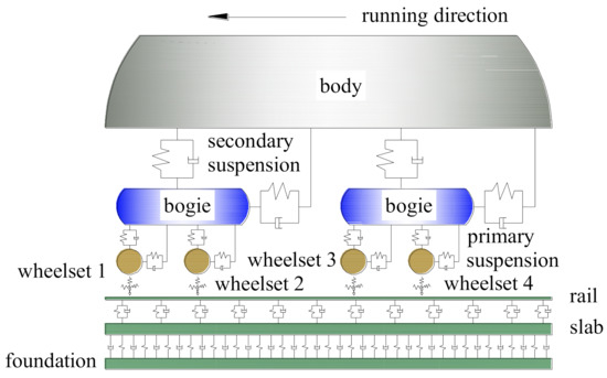
Figure 5.
Diagram of vehicle–track space rigid–flexible coupling model.
4.1.2. Validation of Model
Using the measured data of rail vibration accelerations, this section verifies the effectiveness of the vehicle–track space rigid–flexible coupling model. The measured interval is located in the line Section 1. Firstly, the rail surface irregularity was measured by the corrugation acquisition instrument, and then the measured rail surface irregularity was added to the rail model for calculation. In the model, the vehicle speed was set as 55 km/h according to the actual operation situation, and the rail measuring point was located on the top surface of the inner rail bottom. The calculation and measurement results of rail vibration accelerations at the measuring point section are shown in Figure 6. It can be seen that the calculation and measurement results are in good agreement, which indicates that the model is credible.
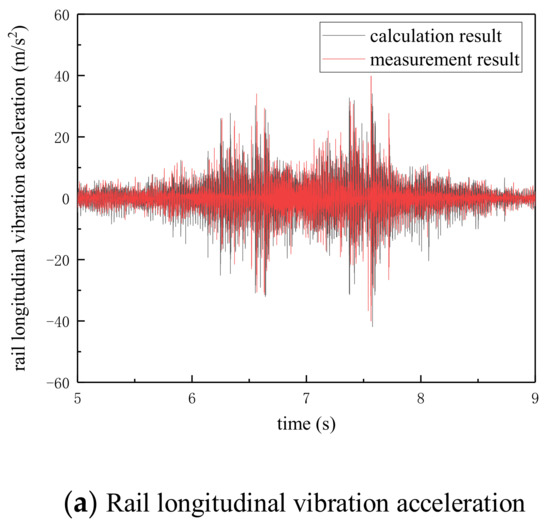
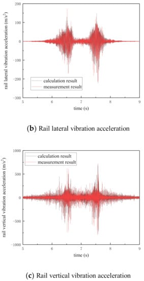
Figure 6.
Comparison of calculation and measurement results. (a) Rail longitudinal vibration acceleration, (b) Rail lateral vibration acceleration. (c) Rail vertical vibration acceleration.
4.2. Wheel–Rail Stick–Slip Characteristics of Small Radius Curve
Referring to the measured line Section 1, the line-type composition was set as (50 m straight line + 100 m transition curve + 300 m circular curve + 100 m transition curve), as shown in Figure 7. The circular curve radius was 300 m, the track superelevation was 100 mm, the track gauge widening was 5 mm, the wheel–rail static coefficient of friction was 0.3, the rail surface had no initial irregularity, and the running speed of the vehicle on the circular curve was 55 km/h. Based on the vehicle–track space rigid–flexible coupling model, the wheel–rail longitudinal and lateral creep forces/creepages, wheel–rail normal force, and other parameters can be obtained by calculation. Meantime, the wheel–rail adhesion coefficient can be obtained by dividing the wheel–rail creep force by the normal force, as shown in Equation (12). This section mainly analyzes the relationship between the wheel–rail adhesion coefficient and creepage to study the cause of rail corrugation in a small radius curve.
where, and are the longitudinal and lateral adhesion coefficients; and are the longitudinal and lateral creep forces; is the normal force.
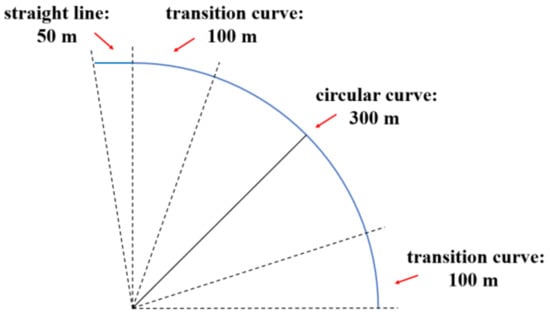
Figure 7.
Schematic diagram of line-type composition.
As the vehicle passes through the curve, the movement form and stress condition of the guiding wheelset and driven wheelset were different. Therefore, two wheelsets of the front bogie of a single vehicle (namely, the guiding wheelset and the driven wheelset, a total of four wheels) were selected for analysis, and the corresponding wheel–rail stick–slip relationship curves are shown in Figure 8 and Figure 9 (the red solid line denotes the fitting curve, similar in the following sections).
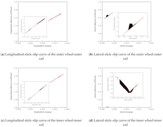
Figure 8.
Wheel–rail stick–slip relation curves of guiding wheelset of small radius curve. (a) Longitudinal stick–slip curve of the outer wheel-outer rail, (b) Lateral stick–slip curve of the outer wheel-outer rail, (c) Longitudinal stick–slip curve of the inner wheel-inner rail, (d) Lateral stick–slip curve of the inner wheel-inner rail.
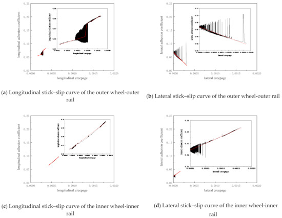
Figure 9.
Wheel–rail stick–slip relation curves of the driven wheelset of small radius curve. Wheel–rail stick–slip relation curves of the driven wheelset of small radius curve. (a) Longitudinal stick–slip curve of the outer wheel-outer rail, (b) Lateral stick–slip curve of the outer wheel-outer rail, (c) Longitudinal stick–slip curve of the inner wheel-inner rail, (d) Lateral stick–slip curve of the inner wheel-inner rail.
It can be seen from Figure 8 that with the increase of the lateral creepage, the lateral adhesion coefficient of the inner rail–inner wheel of the guiding wheelset first decreased and then increased, and a negative slope phenomenon appeared in the wheel–rail stick–slip curve, that is, with the increase of the lateral velocity difference between the inner wheel and inner rail, the lateral adhesion coefficient of the wheel–rail interface decreased, which illustrates that the lateral relative slip between the inner wheel and inner rail occurred. The alternation of wheel–rail lateral adhesion and slip states leads to the wheel–rail lateral torsional stick–slip vibration, and the alternation of the two states is cyclic, so as to achieve the smooth passage of the vehicle through the curve. When the inner wheel and inner rail stick together, the rail wear is small; when the inner wheel slips on the inner rail, the rail wear is large, so with the increase of the number of vehicles running, the inner rail surface eventually forms a wavy wear. The longitudinal adhesion coefficient of the inner rail–inner wheel and the longitudinal and lateral adhesion coefficients of the outer rail–outer wheel are all positively correlated with the corresponding creepages, and there is no negative slope phenomenon, indicating that there will be no microscopic slip at the corresponding wheel–rail interface, so it is not easy to produce rail corrugation.
According to Figure 9, it can be found that the lateral stick–slip curve of the outer rail–outer wheel of the driven wheelset had a negative slope, and the other wheel–rail stick–slip curves had no obvious negative slope phenomenon, which shows that the outer rail–outer wheel of the driven wheelset will also produce lateral torsional stick–slip vibration, which causes the outer rail to form corrugation. However, the adhesion coefficient of 0.069 required for the lateral torsional stick–slip vibration of the outer rail–outer wheel of the driven wheelset was much greater than the adhesion coefficient of 0.0084 required for the lateral torsional stick–slip vibration of inner rail–inner wheel of the guiding wheelset. Therefore, the lateral torsional stick–slip vibration intensity of the outer rail–outer wheel of the driven wheelset is relatively weak, that is, the outer rail corrugation of a small radius curve is relatively slight or not easy to occur. If the rail surface irregularity is considered, the strong lateral torsional stick–slip vibration may happen between the outer rail and outer wheel of the driven wheelset, which may lead to obvious corrugation on the outer rail.
The above analysis shows that on the small radius curve, the lateral torsional stick–slip vibration of inner rail–inner wheel of the guiding wheelset leads to the generation of the inner rail corrugation, and the lateral torsional stick–slip vibration of outer rail–outer wheel of the driven wheelset may also occur, but the intensity is weak and the probability is low. Therefore, the inner rail corrugation on the small radius curve is more serious, and the outer rail corrugation is less or does not exist, which is consistent with the field measurement.
4.3. Wheel–Rail Stick–Slip Characteristics of Large Radius Curve
This section focuses on the wheel–rail stick–slip characteristics of a large radius curve. Referring to the measured line Section 4, the line-type composition is the same as Section 4.1, the circle curve radius was set as 700 m, the track superelevation was 50 mm, the track gauge was 1435 mm, the wheel–rail static coefficient of friction was 0.3, the rail surface was free of initial irregularity, and the running speed of vehicle on the circular curve was 64 km/h. By model calculation, the corresponding wheel–rail stick–slip curves could be obtained, as shown in Figure 10 and Figure 11.
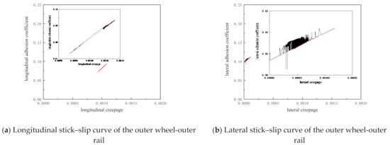
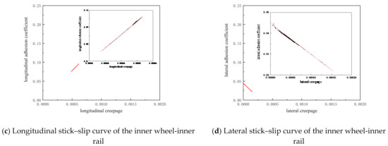
Figure 10.
Wheel–rail stick–slip relation curves of guiding wheelset of large radius curve. (a) Longitudinal stick–slip curve of the outer wheel-outer rail, (b) Lateral stick–slip curve of the outer wheel-outer rail, (c) Longitudinal stick–slip curve of the inner wheel-inner rail, (d) Lateral stick–slip curve of the inner wheel-inner rail.
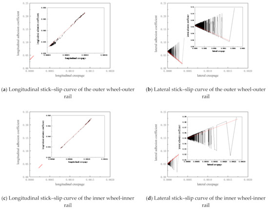
Figure 11.
Wheel–rail stick–slip relation curves of the driven wheelset of large radius curve. (a) Longitudinal stick–slip curve of the outer wheel-outer rail, (b) Lateral stick–slip curve of the outer wheel-outer rail, (c) Longitudinal stick–slip curve of the inner wheel-inner rail, (d) Lateral stick–slip curve of the inner wheel-inner rail.
As can be seen from Figure 10, similar to the case of the small radius curve, on the large radius curve track, the lateral stick–slip characteristic curve of the inner rail–inner wheel of the guiding wheelset also appears as a negative slope phenomenon, which indicates that the lateral relative slip of the inner rail–inner wheel occurs, resulting in the lateral torsional stick–slip vibration, and it is easy to induce the formation of corrugation on the inner rail surface. However, compared with the adhesion coefficient of 0.0084 required for the lateral torsional stick–slip vibration of the inner rail–inner wheel of the guiding wheelset on the small radius curve, the adhesion coefficient of 0.044 required for the lateral torsional stick–slip vibration of the inner rail–inner wheel of the guiding wheelset on the large radius curve is higher, thus the vibration intensity is weak and the occurrence probability is relatively low. There is no obvious negative slope in the other wheel–rail stick–slip characteristic curves, which illustrates that it will not produce corresponding torsional stick–slip vibration and has little influence on the formation of rail corrugation.
It can be seen from Figure 11 that the lateral stick–slip characteristic curves of the outer rail–outer wheel and inner rail–inner wheel of the driven wheelset have some negative slope sections, and the negative slope range corresponding to the lateral stick–slip characteristic curve of the outer rail–outer wheel is more than that of the inner rail–inner wheel, which indicates that the lateral torsional stick–slip vibration of the driven wheelset has a certain influence on the formation of inner and outer rail corrugations. However, because the adhesion coefficients of the outer rail–outer wheel and inner rail–inner wheel of the driven wheelset are higher, which are 0.066 and 0.052, respectively, the vibration intensity is weak and the occurrence probability is low. Meanwhile, it should be noted that compared with the adhesion coefficient of 0.069 required for the lateral torsional stick–slip vibration of the outer rail–outer wheel of the driven wheelset on the small radius curve, the adhesion coefficient of 0.066 that is required for the lateral torsional stick–slip vibration of the outer rail–outer wheel of the driven wheelset on the large radius curve is slightly smaller, which shows that with the increase of the curve radius, the intensity of the lateral torsional stick–slip vibration of the outer rail–outer wheel of the driven wheelset is enhanced, but the corresponding adhesion coefficient is still large, so the outer rail is not easy to produce corrugation when the rail surface is smooth. In addition, compared with the inner rail–inner wheel of the driven wheelset on the small radius curve, the inner rail–inner wheel of the driven wheelset on the large radius curve has a slight lateral torsional stick–slip vibration, which shows that with the increase of the curve radius, the contact stick–slip behaviors of inner rail–inner wheel of the driven wheelset have a certain effect on the formation of inner rail corrugation, but this effect is much smaller than that of the inner rail–inner wheel of the guiding wheelset. The wheel–rail longitudinal adhesion coefficient of the driven wheelset is positively correlated with the longitudinal creepage, so the longitudinal adhesion characteristics have little influence on the formation of the inner and outer rail corrugations.
It can be seen from the above that the lateral torsional stick–slip vibration of the inner rail–inner wheel of the guiding wheelset is easy to lead to the generation of inner rail corrugation on the curve track with a large radius, but the degree of inner rail corrugation decreases compared with that on the curve track with a small radius. Corrugation is still not easy to be formed on the outer rail of large radius curve, but if the rail surface is not smooth, it may cause the appearance of the outer rail corrugation.
4.4. Wheel–Rail Stick–Slip Characteristics of Straight Line
Referring to the actual line No. 8, the length of the straight line was set as 500 m, the track gauge was 1435 mm, the wheel–rail static coefficient of friction was 0.3, the initial irregularity was not considered on the rail surface, and the vehicle running speed was 70 km/h. The vehicle–track coupling model was used for calculation, and the corresponding wheel–rail stick–slip characteristic curves were obtained, as shown in Figure 12 and Figure 13.
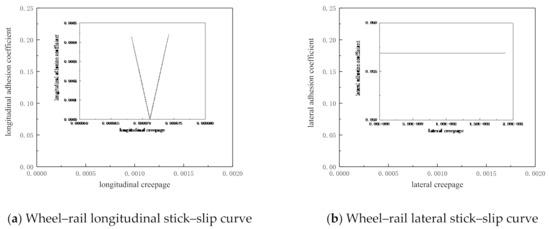
Figure 12.
Wheel–rail stick–slip relation curves of the guiding wheelset of straight line. (a) Wheel–rail longitudinal stick–slip curve, (b) Wheel–rail lateral stick–slip curve.
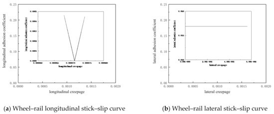
Figure 13.
Wheel–rail stick–slip relation curves of the driven wheelset of straight line. (a) Wheel–rail longitudinal stick–slip curve, (b) Wheel–rail lateral stick–slip curve.
Because the vehicle runs at a constant speed on the straight track, the traction force of the vehicle was constant, which was equal to the running resistance of the vehicle, and the motion state of the vehicle was also constant, therefore, the variation ranges of the wheel–rail creepages and adhesion coefficients were very small, as shown in Figure 12 and Figure 13. The wheel–rail longitudinal stick–slip curves of the guiding wheelset and the driven wheelset on the straight line had similar shapes, but the ends of the two curves were different. The amplitudes of wheel–rail lateral stick–slip curves were consistent, but the variation range of wheel–rail lateral creepage of the driven wheelset was relatively large. With the increase of lateral creepage, the wheel–rail lateral adhesion coefficient remained unchanged, indicating that there was no wheel–rail torsional stick–slip vibration in the lateral direction. With the increase of longitudinal creepage, the wheel–rail longitudinal adhesion coefficient decreased first and then increased, that is, the wheel–rail longitudinal stick–slip curve had a negative slope phenomenon. However, the variation range of longitudinal creepage corresponding to the wheel–rail longitudinal stick–slip curve was very small, about 0.0000075, thus, the intensity of the wheel–rail longitudinal torsional stick–slip vibration was weak and it was not easy to form rail corrugation. If the traction behavior of the vehicle changes suddenly and the surface state of the straight rail is bad, the variation range of longitudinal creepage may be expanded, the wheel–rail longitudinal torsional stick–slip vibration will be intensified, and then rail corrugation will be generated, which may be the formation mechanism of rail corrugation on the measured straight section.
Through the analysis of the wheel–rail stick–slip characteristics on the straight line, it is found that the formation mechanism of rail corrugation on the straight line is different from that on the curve line. The formation of rail corrugation on the straight line is mainly related to the wheel–rail longitudinal torsional stick–slip vibration, while the formation of rail corrugation on the curve line is mainly related to the wheel–rail lateral torsional stick–slip vibration. This conclusion can well explain the corrugation situation on the measured line, and also verify the cause theory of rail corrugation described in Section 3.
5. Conclusions
Based on the actual measurement on-site, the occurrence situation of rail corrugation was investigated first. Then, the formation mechanism of rail corrugation was explained from the theory of the wheel–rail contact stick–slip by analyzing the curve passing form of a single wheelset. Finally, the vehicle-track space rigid-flexible coupling model is used to study the relationship between the wheel–rail stick–slip characteristics and rail corrugation, and the wheel–rail contact stick–slip theory was verified. The following conclusions can be drawn:
(1) The results of field investigation show that most of the rail corrugations occur on the inner rail surface of curve tracks with a radius less than 700 m, and the smaller the curve radius is, the more serious the rail corrugation is.
(2) The analysis of the curve passing form of single wheelset shows that the wheel–rail lateral torsional stick–slip vibration is the main reason for the corrugation on the curve track, while the corrugation on the straight track may be related to the wheel–rail longitudinal torsional stick–slip vibration.
(3) Based on the vehicle–track space rigid–flexible coupling model, the wheel–rail stick–slip characteristics on tracks with different curve radii were studied. On the small radius curve track, the lateral torsional stick–slip vibration of the inner rail–inner wheel of the guiding wheelset induces the generation of inner rail corrugation, and the lateral torsional stick–slip vibration of outer rail–outer wheel of the driven wheelset may also occur, but the intensity is weak and the probability is low. Therefore, on the small radius curve, the inner rail is worn seriously, while the outer rail is worn slightly or not. On the large radius curve track, the lateral torsional stick–slip vibration of inner rail–inner wheel of the guiding wheelset is also easy to cause the inner rail corrugation, but the degree of the inner rail corrugation is decreased compared with that on the small radius curve track. Corrugation is still not easy to be formed on the outer rail of a large radius curve, but if the rail surface is not smooth, it may cause the appearance of the outer rail corrugation. The formation mechanism of rail corrugation on the straight line is different from that on the curve line, which is mainly related to the wheel–rail longitudinal torsional stick–slip vibration. If the traction behavior of the vehicle changes suddenly [38] and the surface condition of the straight rail is not good [39], the wheel–rail longitudinal torsional stick–slip vibration may be aggravated, which may further lead to rail corrugation.
(4) The conclusions of this paper can well explain the rail corrugation phenomenon on the curve and straight tracks, and also verify the theory of rail corrugation caused by wheel–rail contact stick–slip characteristics.
Author Contributions
Conceptualization, methodology, software, validation, formal analysis, investigation, writing–original draft preparation, writing–review and editing, Z.W. (Zhiqiang Wang); conceptualization, resources, writing–review and editing, supervision, project administration, funding acquisition, Z.L. (Zhenyu Lei). All authors have read and agreed to the published version of the manuscript.
Funding
This study was funded by the National Natural Science Foundation of China, grant number 11772230.
Institutional Review Board Statement
Not applicable.
Informed Consent Statement
Not applicable.
Data Availability Statement
All data, models, and code generated or used during the study appear in the submitted article.
Conflicts of Interest
The authors declare no potential conflicts of interest with respect to the research, authorship, and/or publication of this article.
References
- Suda, Y.; Hanawa, M.; Okumura, M.; Iwasa, T. Study on rail corrugation in sharp curves of commuter line. Wear 2002, 253, 193–198. [Google Scholar] [CrossRef]
- Sheng, X.; Thompson, D.J.; Jones, C.J.C.; Xie, G.; Iwnicki, S.D.; Allen, P.; Hsu, S.S. Simulations of roughness initiation and growth on railway rails. J. Sound Vib. 2006, 293, 819–829. [Google Scholar] [CrossRef]
- Jin, X.S.; Wen, Z.F.; Wang, K.Y.; Zhou, Z.R.; Liu, Q.Y.; Li, C.H. Three-dimensional train-track model for study of rail corrugation. J. Sound Vib. 2006, 293, 830–855. [Google Scholar] [CrossRef]
- Wu, T.X.; Thompson, D.J. An investigation into rail corrugation due to micro-slip under multiple wheel/rail interactions. Wear 2005, 258, 1115–1125. [Google Scholar] [CrossRef] [Green Version]
- Sato, Y.; Matsumoto, A.; Knothe, K. Review on rail corrugation studies. Wear 2002, 253, 130–139. [Google Scholar] [CrossRef]
- Grassie, S.L.; Kalousek, J. Rail Corrugation: Characteristics, causes and treatments. Proc. Inst. Mech. Eng. Part F J. Rail Rapid Transit 1993, 207, 57–68. [Google Scholar] [CrossRef]
- Knothe, K.; Grassie, S.L. Modelling of railway track and vehicle/track interaction at high frequencies. Veh. Syst. Dyn. 1993, 22, 209–262. [Google Scholar] [CrossRef]
- Guan, Q.H.; Zhou, Y.M.; Li, W.; Wen, Z.F.; Jin, X.S. Study on the P2 resonance frequency of vehicle track system. J. Mech. Eng. 2019, 55, 118–127. [Google Scholar] [CrossRef] [Green Version]
- Pan, B.; Wang, A.B.; Gao, X.G.; Liu, L. Effects of lateral dynamic response characteristics of wheel-rail coupling systems on rail corrugation. Noise Vib. Control 2020, 40, 132–137. [Google Scholar]
- Zhou, Z.J.; Li, W.; Wen, Z.F.; Xiao, G.F. Cause analysis of metro short-wavelength rail corrugation based on dynamic characteristics of wheel-rail structure. J. Vib. Meas. Diagn. 2020, 40, 1040–1047. [Google Scholar]
- Liu, X.G.; Wang, P. Investigation of the generation mechanism of rail corrugation based on friction induced torsional vibration. Wear 2021, 468–469, 203593. [Google Scholar] [CrossRef]
- Gu, Y.L.; Zhao, G.T.; Wang, H.Y.; Wen, Z.F.; Jin, X.S. Effect of track vibration characteristics on rail corrugation of high speed railway. China Railw. Sci. 2016, 37, 42–47. [Google Scholar]
- Zhang, P.; Wang, A.B.; Wang, Z.Q.; Xu, N.; Zhang, Z.Y. Influence of track parameters on rail Pinned-Pinned vibration. Urban Mass Transit 2016, 19, 72–76. [Google Scholar]
- Wang, Z.Q.; Lei, Z.Y. The cause and development characteristics of straight track corrugation in metro. Sci. Technol. Eng. 2020, 20, 12118–12124. [Google Scholar]
- Matsumoto, A.; Sato, Y.; Ono, H.; Tanimoto, M.; Oka, Y.; Miyauchi, E. Formation mechanism and countermeasures of rail corrugation on curved track. Wear 2002, 253, 178–184. [Google Scholar] [CrossRef]
- Ishida, M.; Moto, T.; Takikawa, M. The effect of lateral creepage force on rail corrugation on low rail at sharp curves. Wear 2002, 253, 172–177. [Google Scholar] [CrossRef]
- Ishida, M.; Akama, M.; Kashiwaya, K.; Kapoor, A. The current status of theory and practice on rail integrity in Japanese railways—rolling contact fatigue and corrugations. Fatigue Fract. Eng. Mater. Struct. 2003, 26, 909–919. [Google Scholar] [CrossRef]
- Yao, H.M.; Shen, G.; Gao, L.J. Formation mechanism of worn profile rail corrugation based on experimental verification. J. Tongji Univ. (Nat. Sci.) 2018, 46, 1427–1432. [Google Scholar]
- Grassie, S.L. Rail corrugation: Characteristics, causes, and treatments. Proc. Inst. Mech. Eng. Part F J. Rail Rapid Transit 2009, 223, 581–596. [Google Scholar] [CrossRef]
- Cui, X.L.; Chen, G.X.; Ouyang, H. Study on the effect of track curve radius on friction-induced oscillation of a wheelset-track system. Tribol. Trans. 2019, 62, 688–700. [Google Scholar] [CrossRef]
- Cui, X.L.; Chen, G.X.; Yang, H.J.; Ouyang, H.; Yan, W.Y. A case study of rail corrugation phenomenon based on the viewpoint of friction-induced oscillation of a wheelset-track system. J. Vibroeng. 2017, 19, 4516–4530. [Google Scholar]
- Cui, X.L.; Chen, G.X.; Zhao, J.W.; Yan, W.Y.; Ouyang, H.; Zhu, M.H. Field investigation and numerical study of the rail corrugation caused by frictional self-excited vibration. Wear 2017, 376–377, 1919–1929. [Google Scholar] [CrossRef]
- Cui, X.L.; Qian, W.J.; Zhang, Q.; Yang, H.G.; Chen, G.X.; Zhu, M.H. Forming mechanism of rail corrugation of a straight track section supported by Cologne-egg fasteners. J. Vib. Shock 2016, 35, 114–118. [Google Scholar]
- Li, X.; Ren, Z.S.; Wang, Z. Study on rail corrugation of ladder-type sleeper track based on vibration characteristics. J. China Railw. Soc. 2020, 42, 38–44. [Google Scholar]
- Zheng, L.X.; Yang, J.J.; Sun, Y.; Zhu, S.Y. Analysis on limiting value of rail corrugation of floating-slab track based on wheel/rail multi-point contact. Chin. Sci. Bull. 2019, 64, 2590–2599. [Google Scholar]
- Li, W.; Du, X.; Wang, H.Y.; Wu, L.; Li, X.; Wen, Z.F.; Jin, X.S. Investigation into the mechanism of type of rail corrugation of metro. J. Mech. Eng. 2013, 49, 26–32. [Google Scholar] [CrossRef]
- Zhang, H.G.; Liu, W.N.; Wu, Z.Z.; Wang, W.B. Causes and treatment for rail corrugation developed on egg fastening system section of metro line. China Railw. Sci. 2014, 35, 22–28. [Google Scholar]
- Li, S.G.; Li, Z.L.; Núñez, A.; Dollevoet, R. New insights into the short pitch corrugation enigma based on 3D-FE coupled dynamic vehicle-track modeling of frictional rolling contact. Appl. Sci. 2017, 7, 807. [Google Scholar] [CrossRef] [Green Version]
- Beshbichi, O.E.; Wan, C.; Bruni, S.; Kassa, E. Complex eigenvalue analysis and parameters analysis to investigate the formation of railhead corrugation in sharp curves. Wear 2019, 450–451, 203150. [Google Scholar] [CrossRef]
- Song, X.L.; Qian, Y.; Wang, K.Y.; Liu, P.F. Effect of rail pad stiffness on vehicle–track dynamic interaction excited by rail corrugation in metro. Transp. Res. Rec. 2020, 2674, 225–243. [Google Scholar] [CrossRef]
- Chen, J.L.; Liu, W.N.; Liu, W.F.; Feng, Q.J.; Zhang, H.G. Demonstration test on treatment solution against rail corrugation occurs at dtvi2 fastener track sections in Beijing metro. J. Mech. Eng. 2018, 54, 64–69. [Google Scholar] [CrossRef]
- Li, W.; Wen, Z.F.; Wang, H.Y.; Zhao, X.; Wang, P. Analysis on the evolution characteristics of rail corrugation on a metro. J. Mech. Eng. 2018, 54, 70–78. [Google Scholar] [CrossRef]
- Liu, W.F.; Zhang, H.G.; Chen, J.L.; Du, L.L. A test of treating rail corrugation by tuned rail damper for Beijing metro. J. Vib. Eng. 2019, 32, 695–700. [Google Scholar]
- Zhao, H.L. Structure and Design of Railway Vehicles; China Railway Publishing House: Beijing, China, 2009. [Google Scholar]
- Wang, Z.Q.; Lei, Z.Y. Parameter influences on rail corrugation of metro tangential track. Int. J. Struct. Stab. Dyn. 2021, 21, 2150034. [Google Scholar] [CrossRef]
- Kalker, J.J. Wheel-rail rolling contact theory. Wear 1991, 144, 243–261. [Google Scholar] [CrossRef]
- Jin, X.S.; Liu, Q.Y. Tribology of Wheel and Rail; China Railway Publishing House: Beijing, China, 2004. [Google Scholar]
- Trimpe, F.; Salander, C. Wheel-rail adhesion during torsional vibration of driven railway wheelsets. Veh. Syst. Dyn. 2021, 59, 785–799. [Google Scholar] [CrossRef]
- Vollebregt, E.; Six, K.; Polach, O. Challenges and progress in the understanding and modelling of the wheel–rail creep forces. Veh. Syst. Dyn. 2021, 59, 1026–1068. [Google Scholar] [CrossRef]
Publisher’s Note: MDPI stays neutral with regard to jurisdictional claims in published maps and institutional affiliations. |
© 2021 by the authors. Licensee MDPI, Basel, Switzerland. This article is an open access article distributed under the terms and conditions of the Creative Commons Attribution (CC BY) license (https://creativecommons.org/licenses/by/4.0/).