
Multi-Objective Parameter Optimization of Flexible Support System of Optical Mirror


Abstract
:Featured Application
Abstract
1. Introduction
2. Modeling of Motion Resistance
2.1. Motion Resistance Modeling of FSS
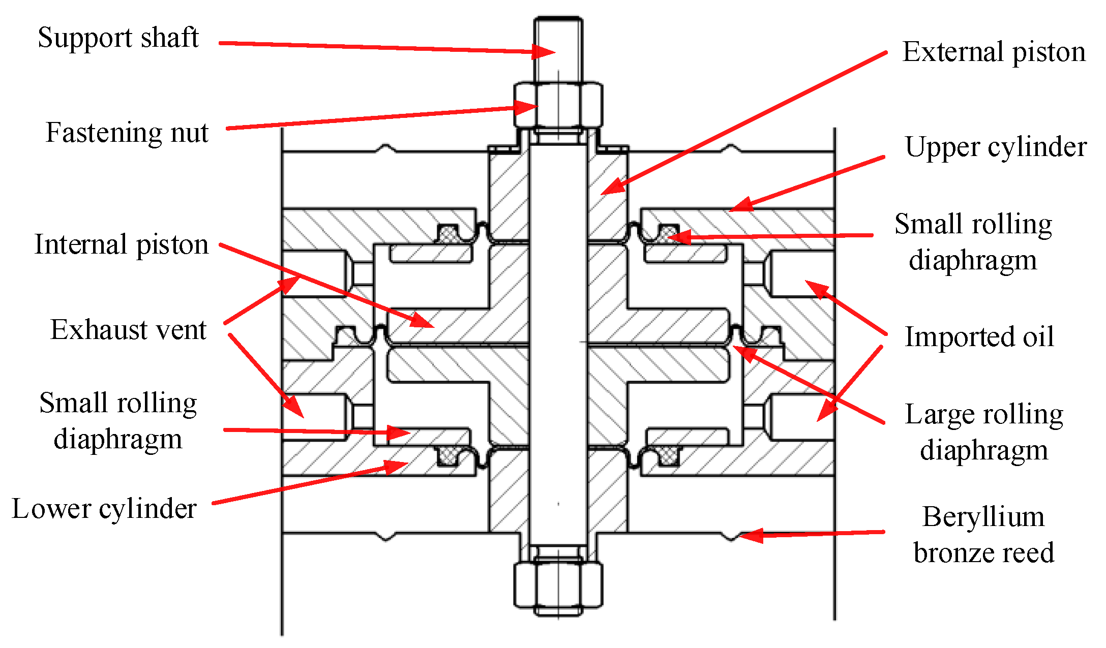
2.2. Internal Resistance Modeling of Single Cylinder
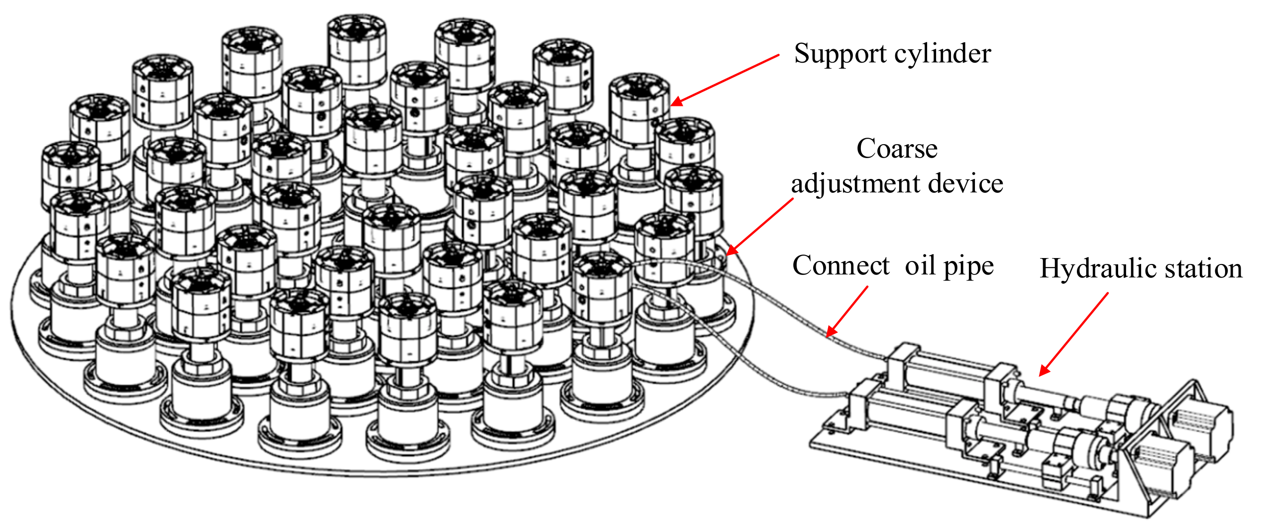
3. Multi-Objective Parameters Optimization Design of Support Cylinder
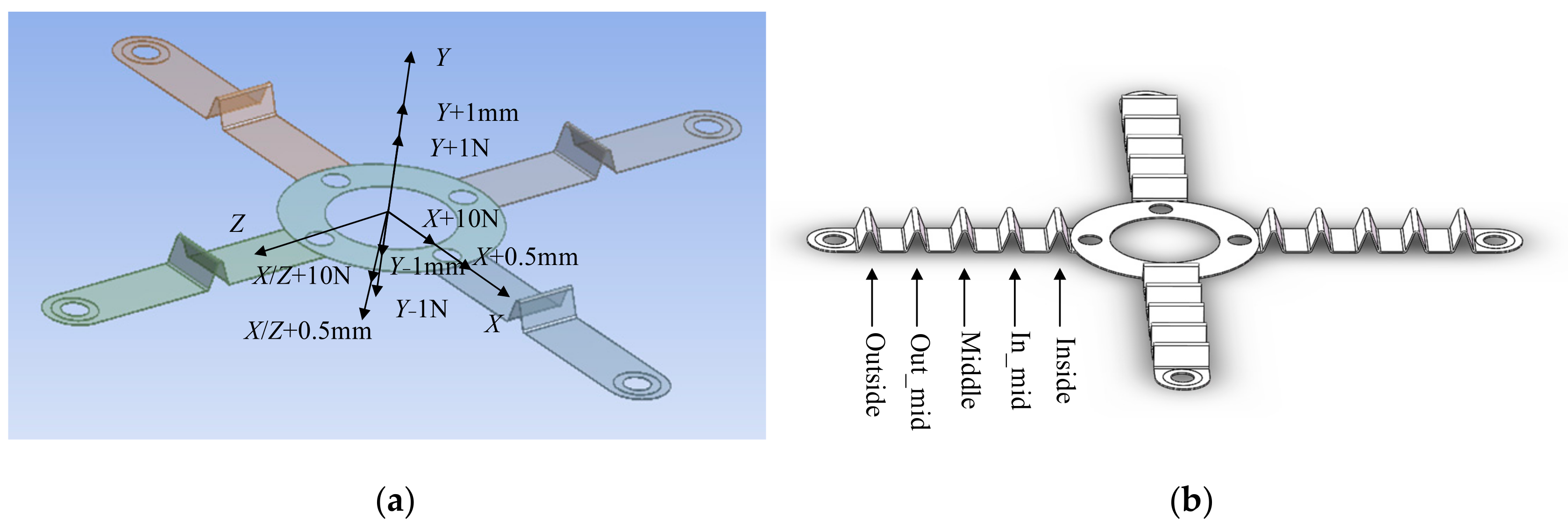
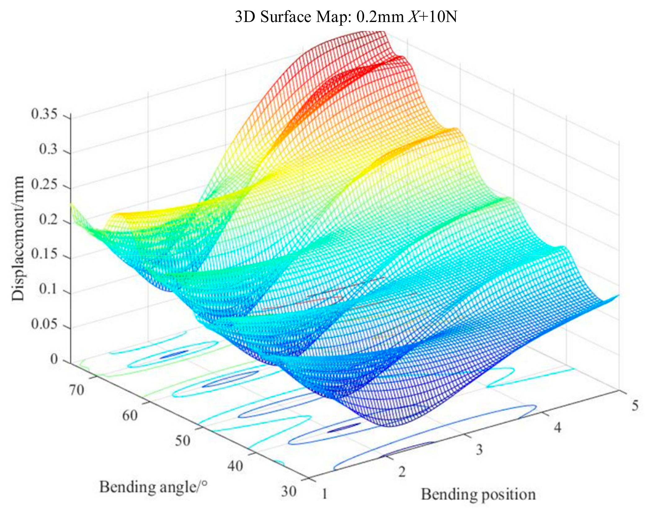
3.1. Multi-Objective Parameters Optimization Design of BBR
- (1)
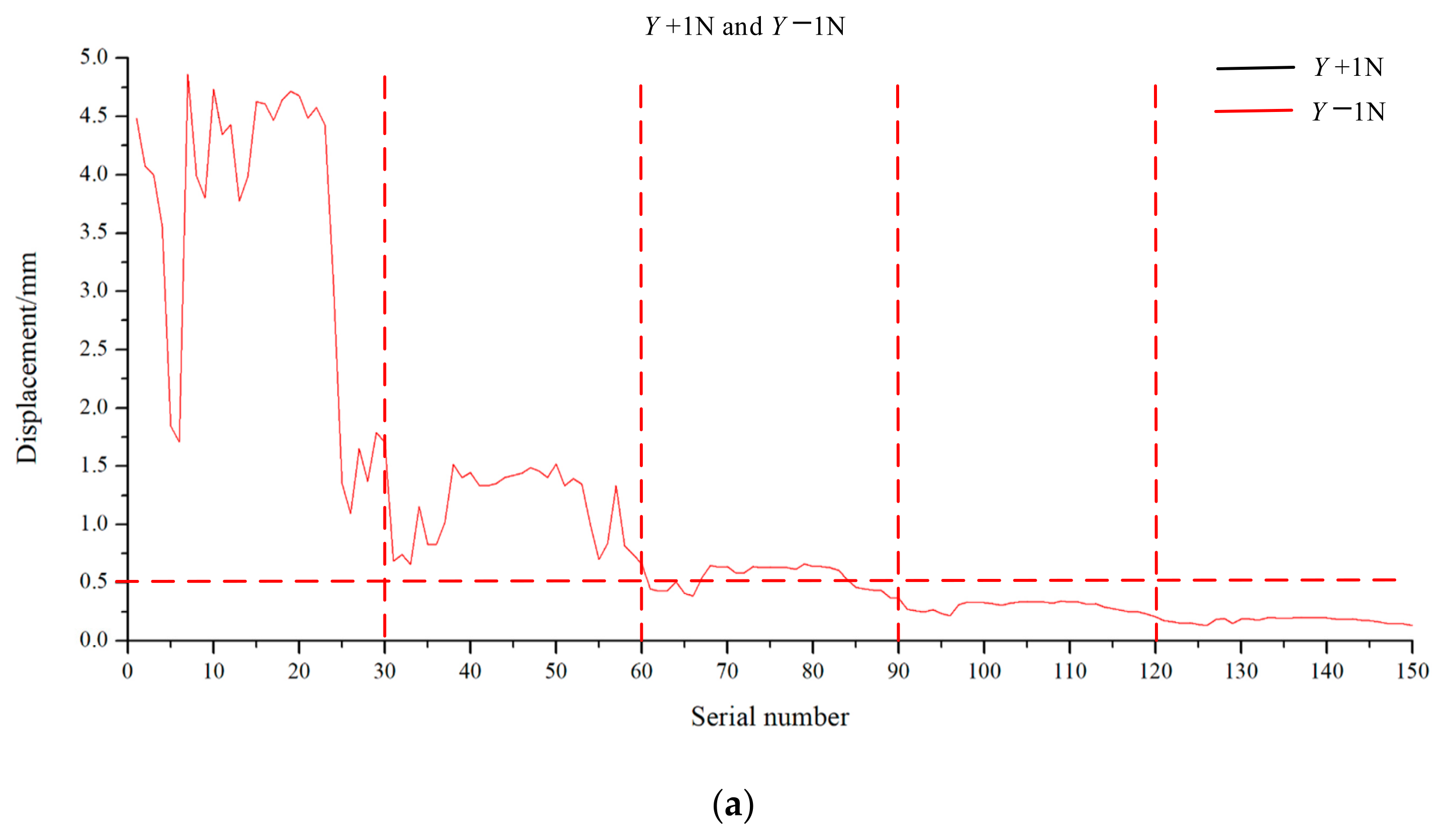
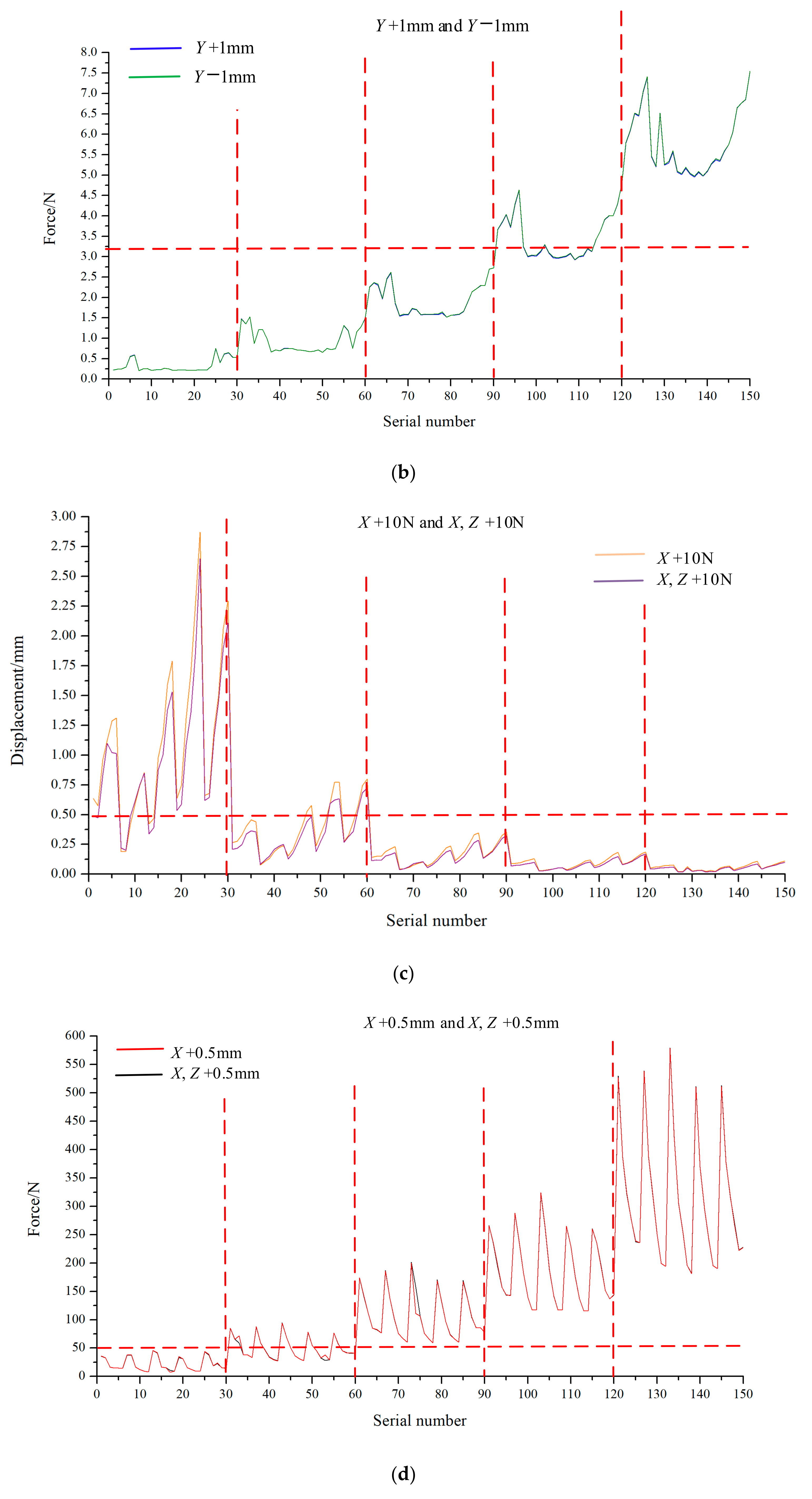
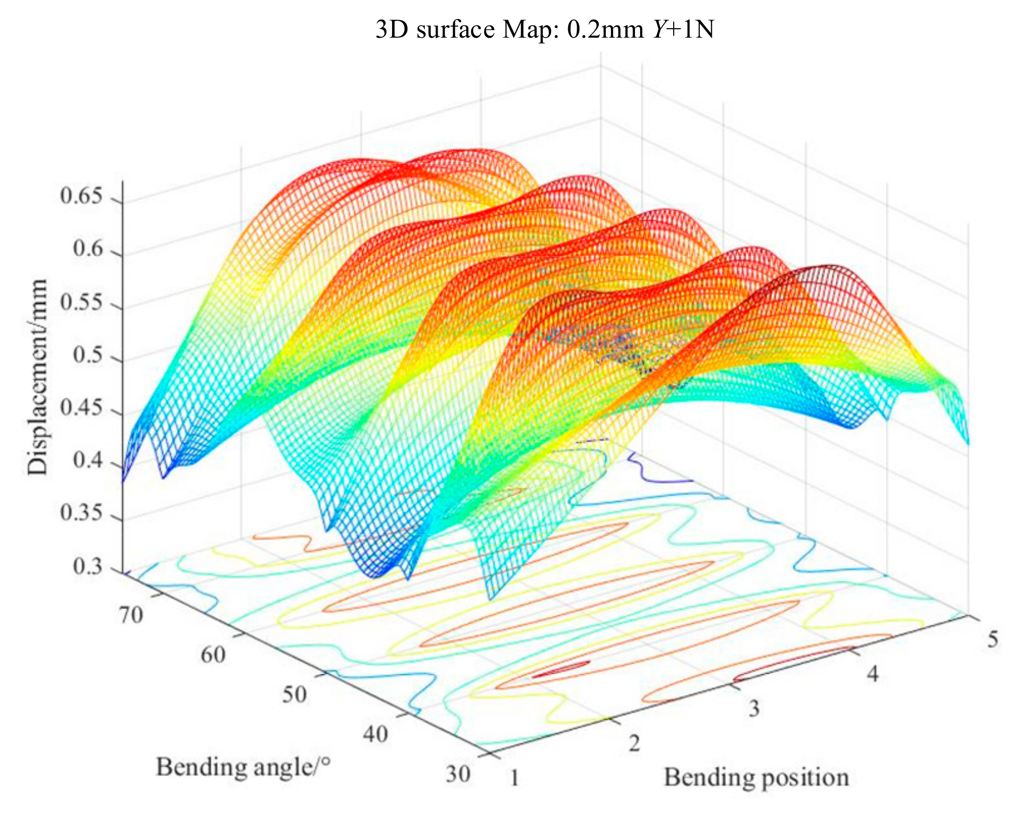
- When a force of +1 N or −1 N is applied in the Y-direction of the BBR, its displacement in this direction is ≥0.5 mm or ≤−0.5 mm.
- (2)
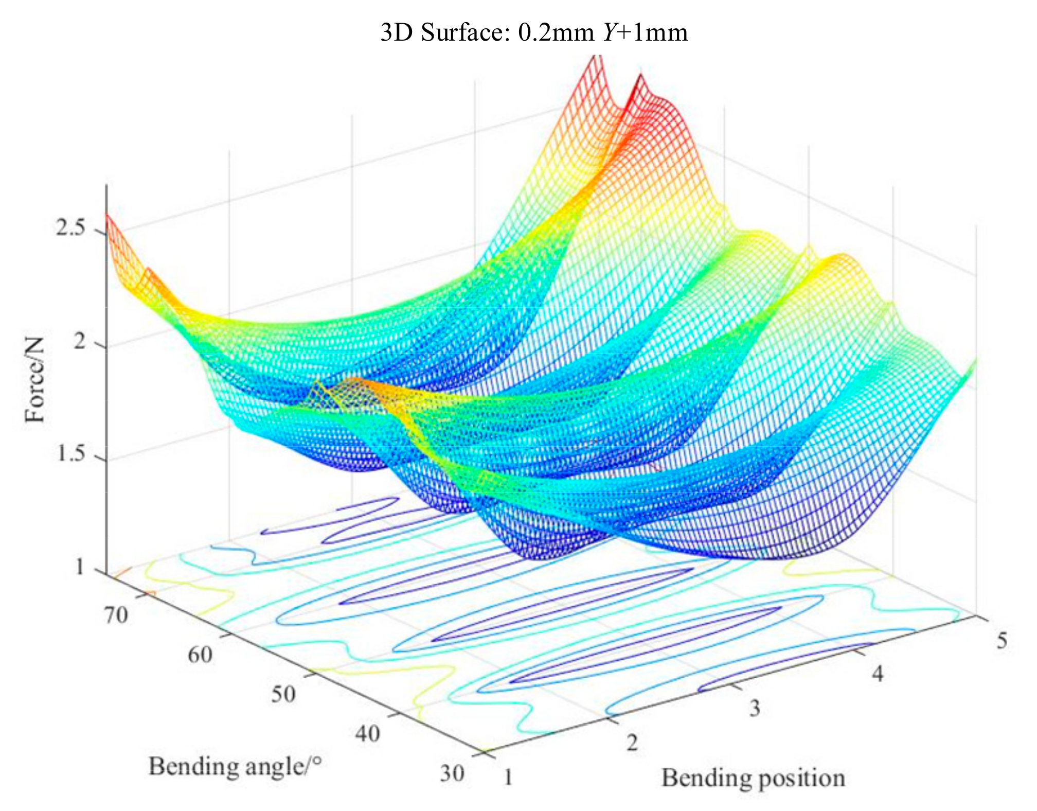
- When the BBR moves +1 mm or −1 mm in the Y-direction, the applied force is ≤3 N.
- (3)
- When a force of +10 N is applied in the X-direction or X, Z centerline direction of the BBR, its displacement is ≤0.5 mm.
- (4)
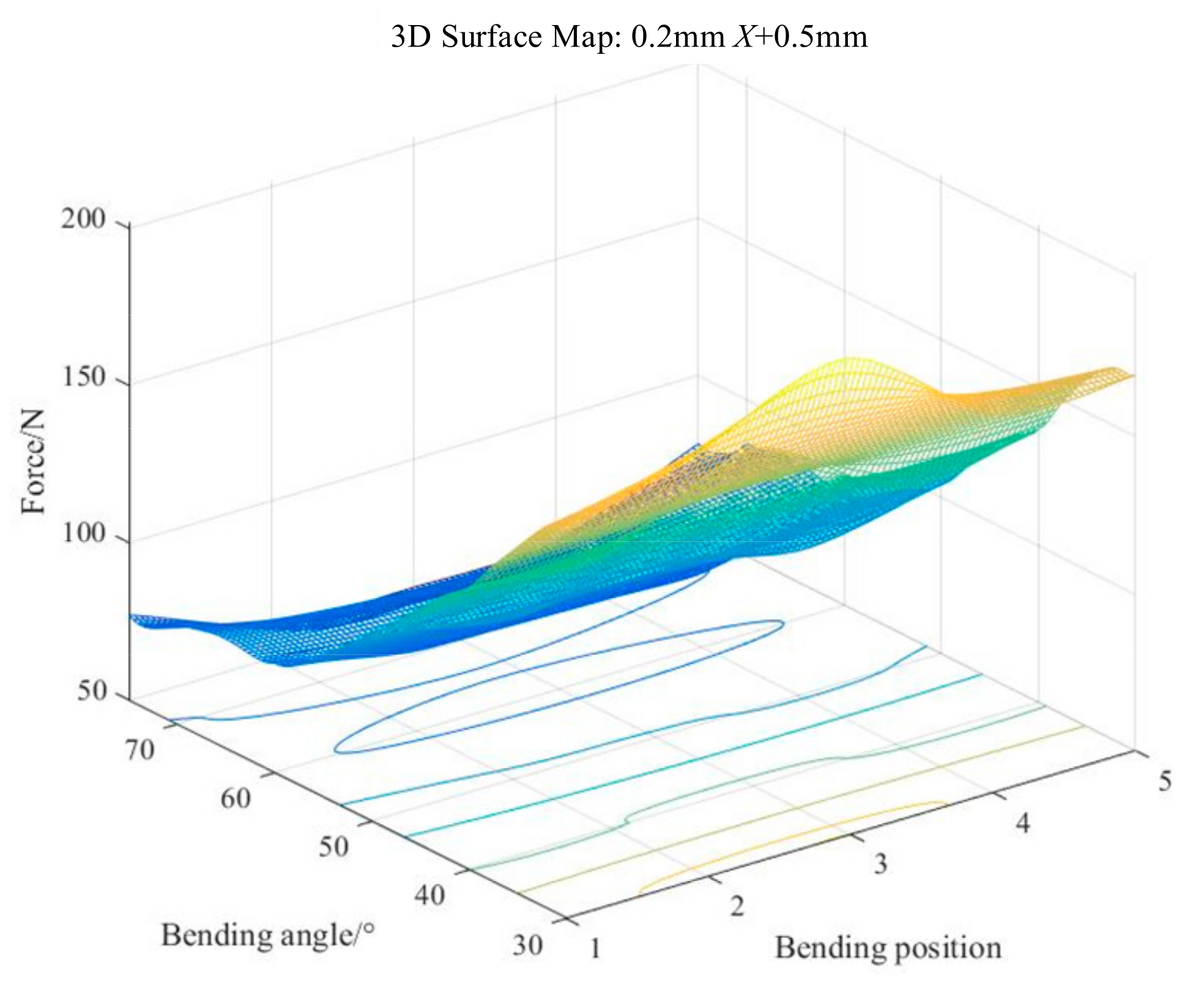
- When the BBR moves 0.5 mm in the X direction or X, Z centerline direction, the applied force is ≥50 N.
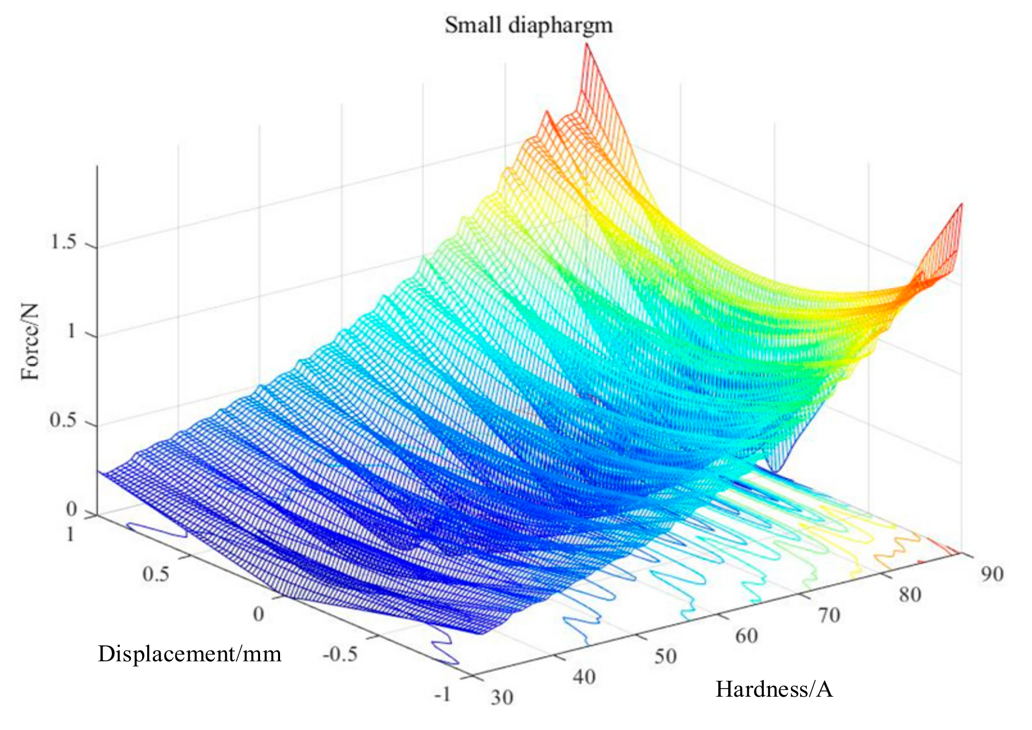
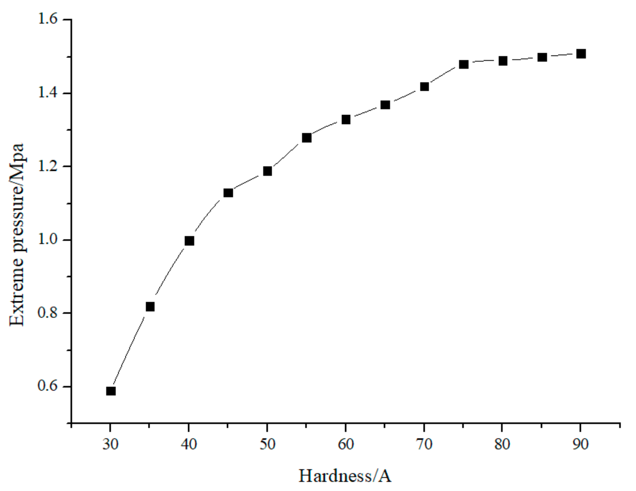
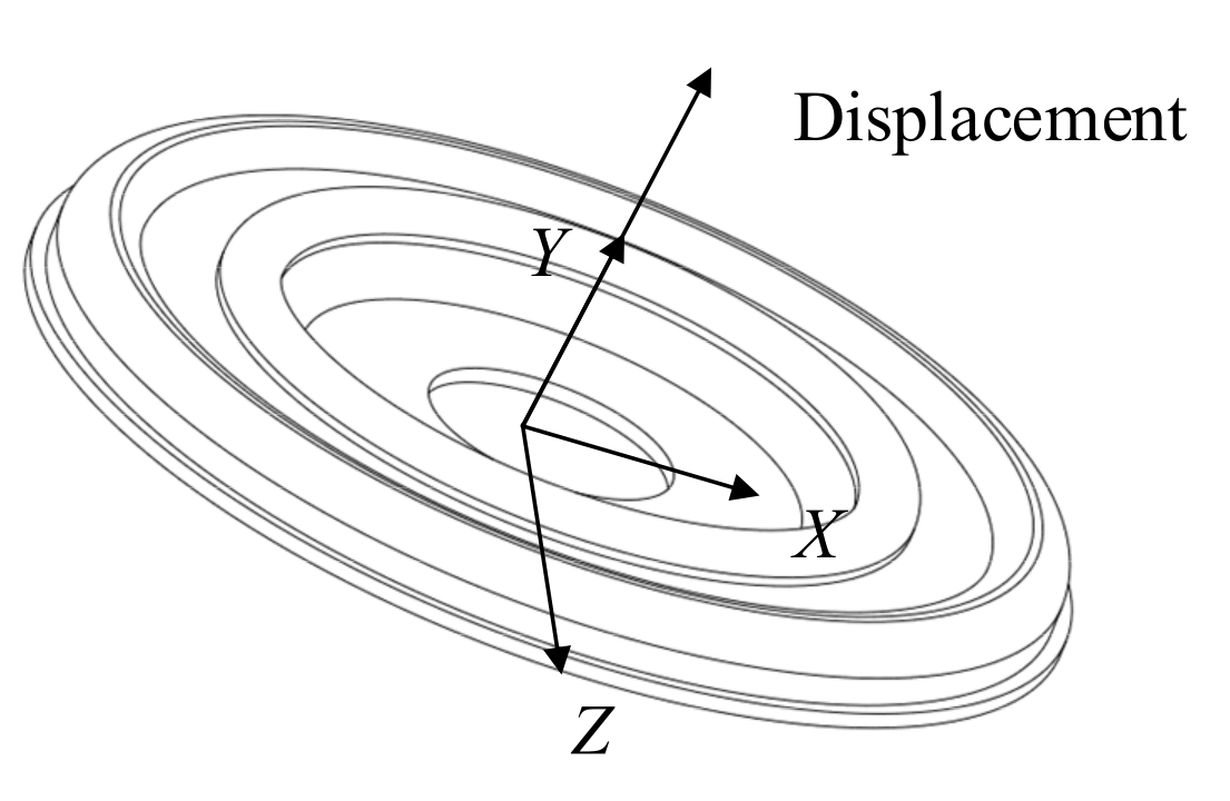
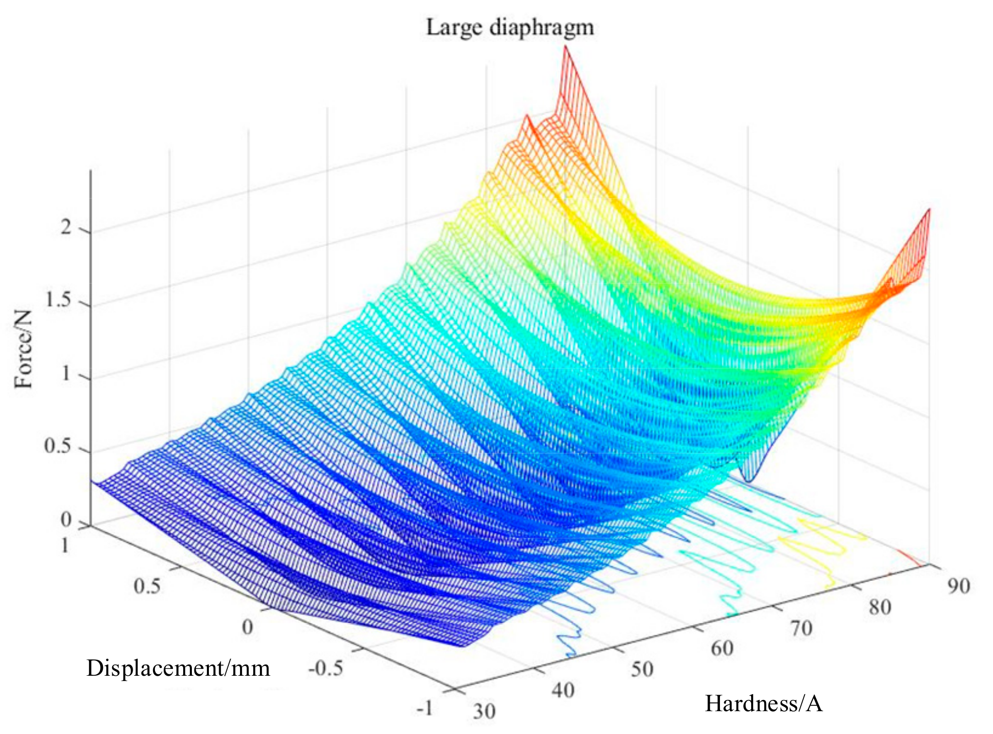
3.2. Multi-Objective Parameters Optimization Design of RD
4. Experimental Analysis
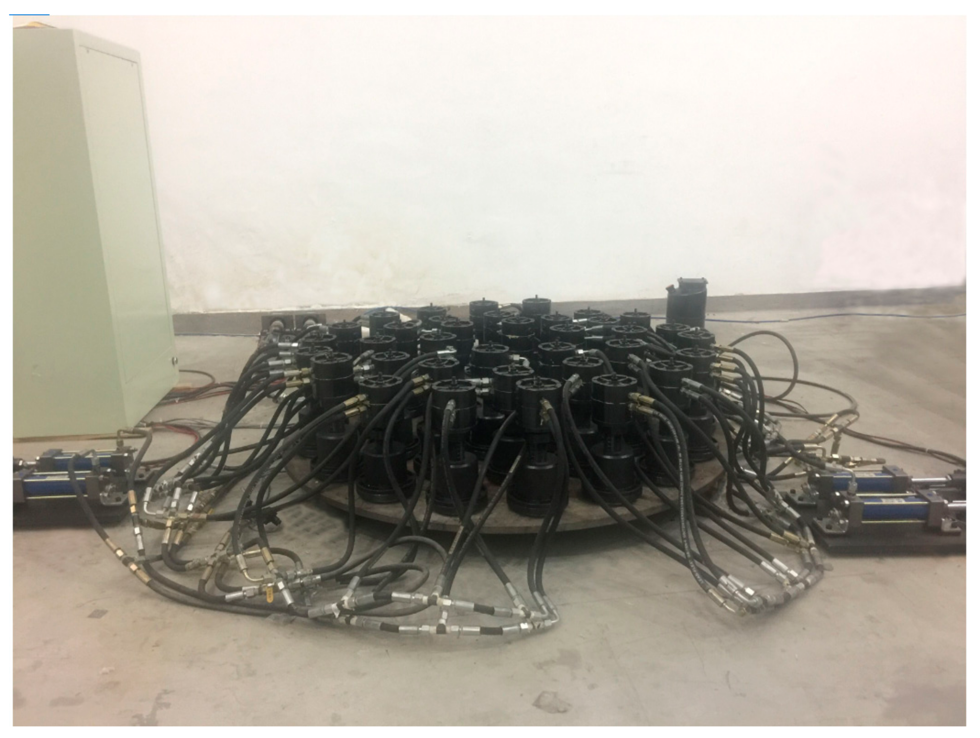
4.1. Pressure Test of FSS
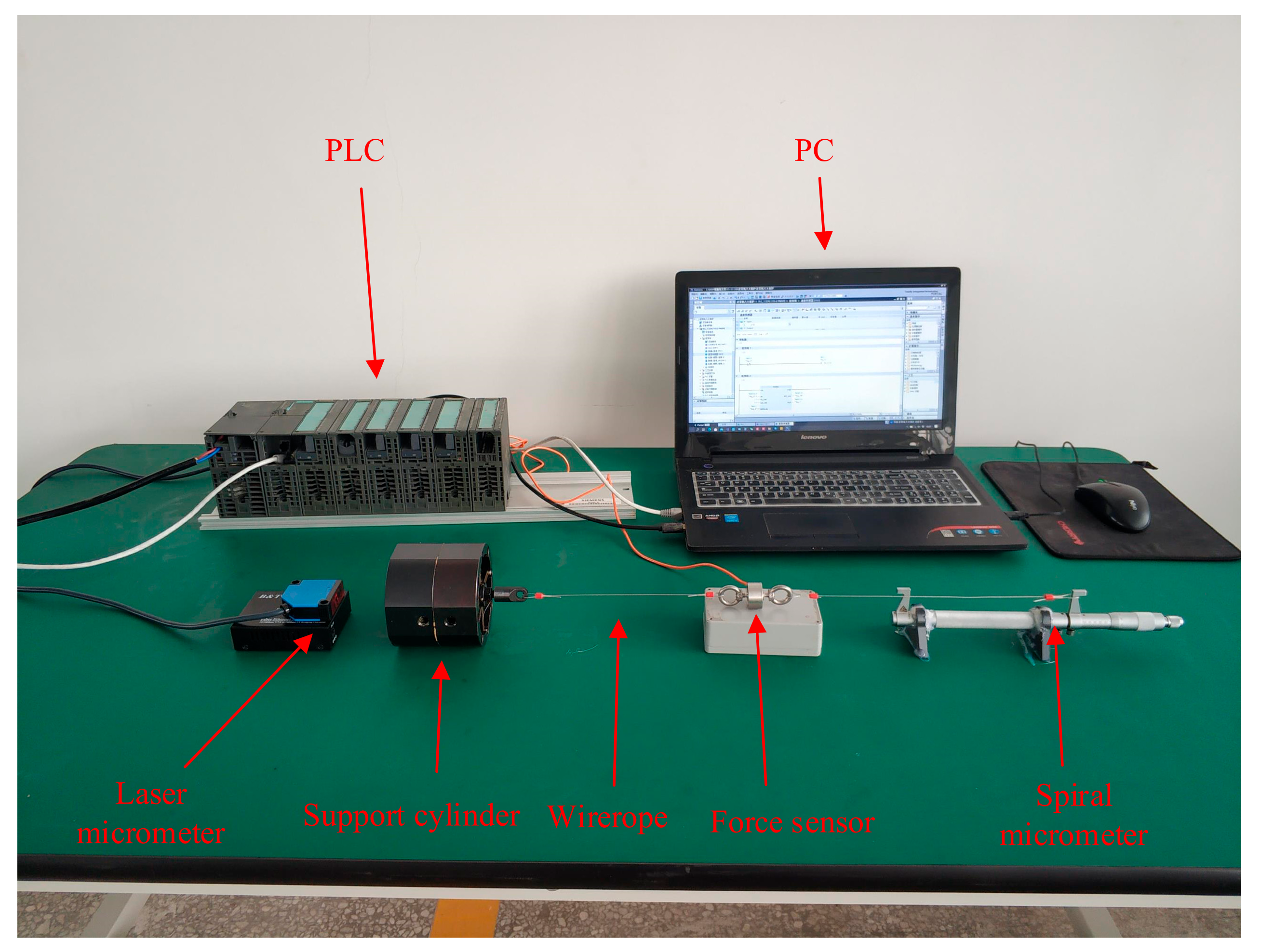
4.2. Measurement Experiment of Internal Resistance of Support Cylinder
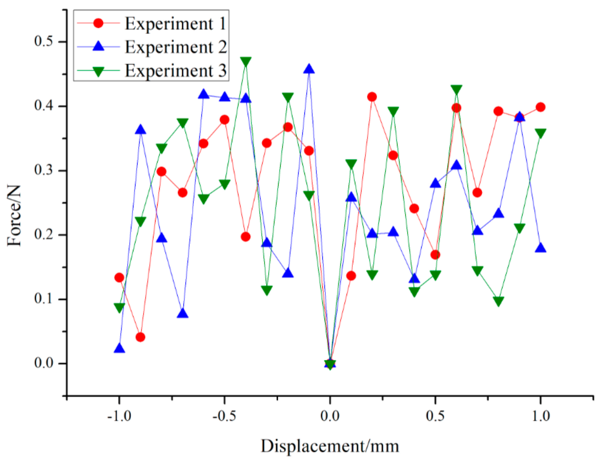
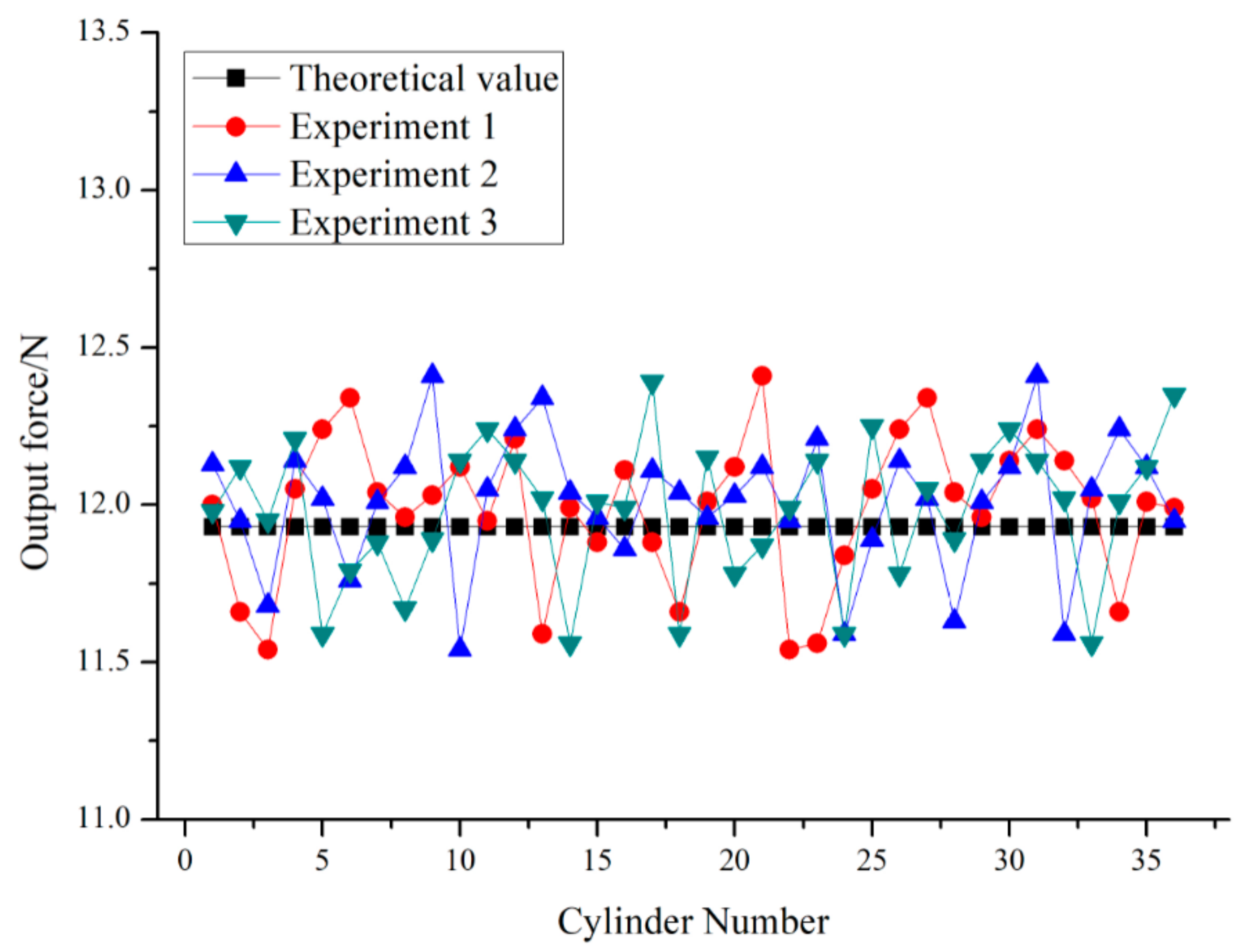
4.3. Force Output Consistency Experiment
5. Conclusions
Author Contributions
Funding
Institutional Review Board Statement
Informed Consent Statement
Data Availability Statement
Conflicts of Interest
References
- Lian, P.Y.; Wang, C.S.; Xue, S.; Xu, Q.; Shi, Y.; Jia, Y.; Xiang, B.; Wang, Y.; Yan, Y. Surface adjustment strategy for a large radio telescope with adjustable dual reflectors. IET Microw. Antennas Propag. 2019, 13, 2669–2677. [Google Scholar] [CrossRef] [Green Version]
- Ma, D.L. Recommended conceptual optical system design for China’s large optical-infrared telescope (LOT). Opt. Express 2018, 26, 108–119. [Google Scholar] [CrossRef]
- Tan, Y.F.; Wang, J.H.; Ren, G.; Xie, Z. Thermal control analysis of a primary mirror for large-aperture telescope. J. Korean Phys. Soc. 2017, 71, 28–36. [Google Scholar] [CrossRef]
- Cheng, G.; Qiu, B.J.; Yang, D.H.; Liu, H. Workspace analysis of 3-CPS parallel micro-manipulator for mirror active adjusting platform. J. Mech. Sci. Technol. 2012, 27, 3805–3816. [Google Scholar] [CrossRef]
- Liu, P.F.; Lin, B.; Zhang, X.F.; Li, Y. Fluid hydrodynamic fixed abrasive grinding based on a small tool. Appl. Opt. 2017, 56, 1453–1459. [Google Scholar] [CrossRef]
- Kong, Y.X.; Cheng, G.; Guo, F.; Gu, W.; Zhang, L. Inertia matching analysis of a 5-DOF hybrid optical machining manipulator. J. Mech. Sci. Technol. 2019, 33, 4991–5002. [Google Scholar] [CrossRef]
- Lan, B.; Wu, X.X.; Li, J.F.; Ming, M.; Liu, X.; Yang, H. Influence of axial-force errors on the deformation of the 4 m lightweight mirror and its correction. Appl. Opt. 2017, 56, 611–619. [Google Scholar] [CrossRef] [PubMed]
- Su, D.Q.; Liang, M.; Yuan, X.Y.; Bai, H.; Cui, X. The optical system of the proposed Chinese 12-m optical/infrared telescope. Mon. Not. Roy. Astron. Soc. 2017, 469, 3792–3801. [Google Scholar] [CrossRef]
- Arnold, L. Uniform-load and actuator influence functions of a thin or thick annular mirror: Application to active mirror support optimization. Appl. Opt. 1996, 35, 1095–1106. [Google Scholar] [CrossRef] [PubMed] [Green Version]
- Li, J.S.; Liu, P.K. Dynamic analysis of 5-DOFs aerostatic spindles considering tilting motion with varying stiffness and damping of thrust bearings. J. Mech. Sci. Technol. 2019, 33, 5199–5207. [Google Scholar] [CrossRef]
- Jin, Z.; Cheng, G.; Xu, S.; Gu, W. Dynamic Disturbance and Error Analysis of Flexible Support System for Large Optical Mirror Processing. Appl. Sci. 2021, 11, 2715. [Google Scholar] [CrossRef]
- Li, B.; Zhao, H.Y.; Xi, J.P.; Ren, D.X. On-machine self-calibration method for compensation during precision fabrication of 900-mm-diameter zerodur aspheric mirror. Int. J. Adv. Manuf. Technol. 2015, 76, 1855–1863. [Google Scholar] [CrossRef]
- Zhou, P.W.; Zhang, D.X.; Liu, G.; Yan, C. Development of space active optics for a whiffletree supported mirror. Appl. Opt. 2018, 58, 5740–5747. [Google Scholar] [CrossRef] [PubMed]
- Kihm, H.; Yang, H.S.; Moon, I.K.; Yeon, J.H. Adjustable bipod flexures for mounting mirrors in a space telescope. Appl. Opt. 2012, 51, 7776–7783. [Google Scholar] [CrossRef]
- Qiang, L.; Shuxin, W.; Fuxiang, T.; Jinguo, T. Research on integrated design method of high-precision space-based active optical large-caliber splicing mirror drive and support. Optik 2019, 204, 163849. [Google Scholar] [CrossRef]
- Yang, L.; Wei, L.; Zhang, L. Thermal compensation design of truss structure for large-scale off-axis three-mirror space telescope. Opt. Eng. 2019, 58, 023109. [Google Scholar] [CrossRef]
- Bi, S.S.; Yao, Y.B.; Zhao, S.S.; Yu, J. Modeling of cross-spring pivots subjected to generalized planar loads. Chin. J. Mech. Eng. 2012, 25, 1075–1085. [Google Scholar] [CrossRef]
- Lei, W.; Lei, Z.; Gong, X.X.; Ma, D. Design and optimization for main support structure of a large-area off-axis three-mirror space camera. Appl. Opt. 2017, 56, 1094–1100. [Google Scholar]
- Hu, H.F.; Luo, X.; Liu, Z.Y.; Zhang, X.; Xue, D.; Zhao, H. Designing a hydraulic support system for large monolithic mirror’s precise in-situ testing-polishing iteration. Opt. Express 2019, 27, 3746–3760. [Google Scholar] [CrossRef]
- Huo, T.; Yu, J.; Zhao, H. Design of a kinematic flexure mount for precision instruments based on stiffness characteristics of flexural pivot. Mech. Mach. Theory 2020, 150, 103868. [Google Scholar] [CrossRef]
- Yan, G.; Bao, Z. Design and analysis for the flexible support structure of high precision lens assembly. Optik 2018, 175, 228–236. [Google Scholar]
- Yu, F.; Xu, S. Flexible support structure based on spring principle for a high precision reflecting mirror. Optik 2020, 207, 164341. [Google Scholar] [CrossRef]
- Dai, X.L.; Xian, H.; Tang, J.L.; Zhang, X.; Zhang, Y. Modification of the support and active correction method for an experimental thin primary mirror. J. Mod. Opt. 2019, 66, 1841–1849. [Google Scholar] [CrossRef]
- Zhang, L.; Wang, W.; Wang, J.; Guo, P.; Hao, L. Design and analysis for the multi-point flexible support structure of large and precision lens. Optik 2019, 193, 162966. [Google Scholar] [CrossRef]
- Wang, Z.S.; Zhang, J.X.; Wang, J.X.; He, X.; Liang, F.; Tian, F.; Liu, X.; Zhao, Y. A method based on exact constraint for supporting space-based large mirror with a diameter of 2.8 m. Optik 2019, 179, 499–504. [Google Scholar] [CrossRef]
- Bo, Q.L.; Liu, H.B.; Lian, M.; Liu, K. The influence of supporting force on machining stability during mirror milling of thin-walled parts. Int. J. Adv. Manuf. Technol. 2019, 101, 2341–2353. [Google Scholar] [CrossRef]
- Bao, Y.; Kang, R.K.; Dong, Z.G.; Zhu, X.; Wang, C.; Guo, D. Multipoint support technology for mirror milling of aircraft skins. Mater. Manuf. Process. 2018, 33, 996–1002. [Google Scholar] [CrossRef]


| Name | Parameter | Name | Parameter |
|---|---|---|---|
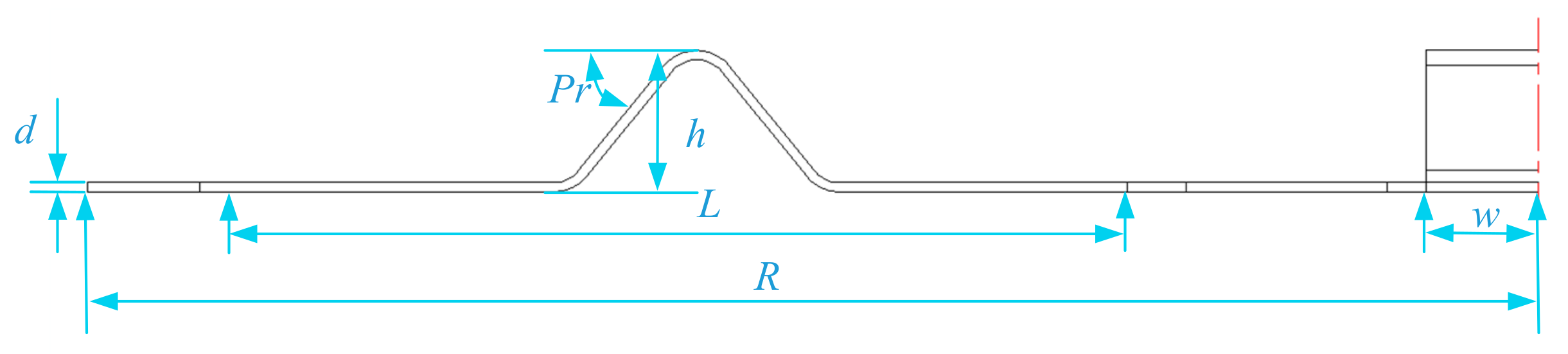
| Elastic beam thickness | Optimization objective | Bending position | Optimization objective |
| Elastic beam width | w = 7 mm | Bending angle | Optimization objective |
| Effective length of elastic beam | L = 27 mm | Installed inner radius | R = 14 mm |
| Install outer radius | R = 24 mm | Bending height | h = 4 mm |
| Name | Numerical Value | Name | Numerical Value |
|---|---|---|---|
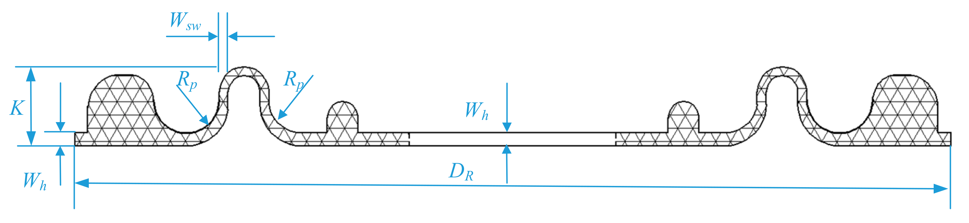
| Chamfer radius | Rp = 1.6 mm | RD thickness | Wh = 0.635 mm |
| Preform height | K = 3.8 mm | Side wall thickness | Wsw = 0.43 mm |
| Installation diameter | Dp1 = 42 mm Dp2 = 78 mm | RD hardness | Optimization objective |
Publisher’s Note: MDPI stays neutral with regard to jurisdictional claims in published maps and institutional affiliations. |
© 2021 by the authors. Licensee MDPI, Basel, Switzerland. This article is an open access article distributed under the terms and conditions of the Creative Commons Attribution (CC BY) license (https://creativecommons.org/licenses/by/4.0/).
Share and Cite
Jin, Z.; Cheng, G.; Pang, Y.; Xu, S.; Yuan, D. Multi-Objective Parameter Optimization of Flexible Support System of Optical Mirror. Appl. Sci. 2021, 11, 8071. https://doi.org/10.3390/app11178071
Jin Z, Cheng G, Pang Y, Xu S, Yuan D. Multi-Objective Parameter Optimization of Flexible Support System of Optical Mirror. Applied Sciences. 2021; 11(17):8071. https://doi.org/10.3390/app11178071
Chicago/Turabian StyleJin, Zujin, Gang Cheng, Yusong Pang, Shichang Xu, and Dunpeng Yuan. 2021. "Multi-Objective Parameter Optimization of Flexible Support System of Optical Mirror" Applied Sciences 11, no. 17: 8071. https://doi.org/10.3390/app11178071
APA StyleJin, Z., Cheng, G., Pang, Y., Xu, S., & Yuan, D. (2021). Multi-Objective Parameter Optimization of Flexible Support System of Optical Mirror. Applied Sciences, 11(17), 8071. https://doi.org/10.3390/app11178071