Article

Application of Simultaneous Symmetric and Cambered Airfoils in Novel Vertical Axis Wind Turbines

by
Sajad Maleki Dastjerdi
1,
Kobra Gharali
1,2,*,
Armughan Al-Haq
2 and
Jatin Nathwani
2,3,4
1
School of Mechanical Engineering, College of Engineering, University of Tehran, Tehran 11155-4563, Iran
2
Waterloo Institute for Sustainable Energy (WISE), University of Waterloo, Waterloo, ON N2L 3G1, Canada
3
Department of Management Sciences, University of Waterloo, Waterloo, ON N2L 3G1, Canada
4
Department of Civil and Environmental Engineering, University of Waterloo, Waterloo, ON N2L 3G1, Canada
*
Author to whom correspondence should be addressed.
Appl. Sci. 2021, 11(17), 8011; https://doi.org/10.3390/app11178011
Submission received: 26 June 2021 / Revised: 24 August 2021 / Accepted: 25 August 2021 / Published: 30 August 2021

Abstract

:
Two novel four-blade H-darrieus vertical axis wind turbines (VAWTs) have been proposed for enhancing self-start capability and power production. The two different airfoil types for the turbines are assessed: a cambered S815 airfoil and a symmetric NACA0018 airfoil. For the first novel wind turbine configuration, the Non-Similar Airfoils 1 (NSA-1), two NACA0018 airfoils, and two S815 airfoils are opposite to each other. For the second novel configuration (NSA-2), each of the S815 airfoils is opposite to one NACA0018 airfoil. Using computational fluid dynamics (CFD) simulations, static and dynamic conditions are evaluated to establish self-starting ability and the power coefficient, respectively. Dynamic stall investigation of each blade of the turbines shows that NACA0018 under dynamic stall impacts the turbine’s performance and the onset of dynamic stall decreases the power coefficient of the turbine significantly. The results show that NSA-2 followed by NSA-1 has good potential to improve the self-starting ability (13.3%) compared to the turbine with symmetric airfoils called HT-NACA0018. In terms of self-starting ability, NSA-2 not only can perform in about 66.67% of 360 ° similar to the wind turbine with non-symmetric airfoils (named HT-S815) but the power coefficient of NSA-2 at the design tip speed ratio of 2.5 is also 4.5 times more than the power coefficient of HT-S815; the power coefficient difference between HT-NACA0018 and HT-S815 (=0.231) is decreased significantly when HT-S815 is replaced by NSA-2 (=0.076). These novel wind turbines are also simple.

1. Introduction

Increasing the share of renewable energy, and specifically wind energy, to meet increased demand for energy is one important strategy for reducing the burden of greenhouse gas emissions and local air pollution. To enhance the cost-effectiveness of electricity generation from wind energy, increased attention to the technological advancement of wind turbines combined with the installation of large-scale wind farms is emerging as an increasing source of new energy supply [1]. VAWTs are well-known and popular types of wind turbines, particularly for small-scale power extraction. Most of the VAWT types have been developed based on the Darrieus design, invented by the French engineer in 1925 [2,3]. This type of turbine has a proper power coefficient, particularly at the small scale used in urban areas [3]. Despite this advantage, self-start capability is one of the critical shortcomings of VAWTs; they cannot start rotating without external help, such as an electrical motor [4]. Due to the importance of vertical axis wind turbines and their positive features compared to horizontal ones, research has focused on improving their performance. The research studies follow two main paths: vertical axis wind turbine self-start capability and power coefficient. Several studies reveal that the focus on improving self-start capability has a negative impact on power production.
Alteration of the main characteristics of VAWTs, such as several blades or airfoils, has been assumed as one way of improving self-starting ability. For instance, three-bladed wind turbines can have better self-starting than two-bladed ones [5], but increasing the number of blades usually reduces the power coefficient [6]. Furthermore, cambered airfoils can help VAWTs rotate at lower wind speeds [7]. However, these airfoils usually reduce the power coefficient [8]. Due to the popularity of NACA airfoils, some studies have tried to find suitable NACA airfoils for self-starting purposes. By way of illustration, NACA2418, a cambered NACA airfoil, has better self-starting with a 1.5° fixed pitch angle than NACA0018, NACA0015, NACA0022, and NACA0024 airfoils [9]. On the other hand, NACA0015 showed the highest power production among them under the same conditions [10]. Another effective way of improving the self-starting ability is modifying the geometry of airfoils [7].
Apart from changing the main parameters of VAWTs (as mentioned above), some innovations can improve self-starting by reducing power production. For instance, double-blade VAWTs, which have two blades in one strut, are useful for this purpose, suggested by Hara et al. [11]. Usage of helical blades instead of straight ones introduced by Alaimo et al. is another solution for starting characteristics [12]. The idea of Bhuyan and Biswas, based on combining a Darrieus rotor with a Savonius one, was beneficial for self-starting ability [13]. They placed the Savonius rotor in the interior area of the Darrieus rotor. Another beneficial arrangement is placing a Savonius rotor above a Darrieus one. This type of VAWT was used in railways by Pan et al. [14]. They proved that coupling a batch-type VAWT with a Darrieus rotor can yield a higher power coefficient as compared to combining one Savonius rotor with one Darrieus one. However, the generated power is still lower than the power coefficient of the H-type VAWTs [15]. An idea that has been proposed recently is using an auxiliary blade close to the main blades. It has been confirmed experimentally and numerically that these VAWTs have a higher self-starting ability [16,17].
A large number of studies have been conducted to increase power production while neglecting the self-starting problem [18,19,20,21,22,23,24,25]. An important inherent parameter of any VAWT is airfoil geometry. It has been shown by Chen et al. that the thickness chord ratio is more effective on the power coefficient than the maximum thickness and the diameter of the leading edge [10]. Further, it has been observed by Ferreira and Geurts that thicker airfoils usually have a lower power coefficient than thinner ones [26]. Carrigan et al. tried to maximize the generated torque by changing the NACA 4-series airfoil parameters, including maximum thickness, maximum camber, and position of maximum camber; they could enhance the power efficiency of VAWTs up to 6% compared with NACA0015 [27]. Another intrinsic parameter of VAWTs is the blade’s angle of attack, which can affect the performance of VAWTs substantially. Hence, the use of pitch angle for changing the angle of attack is a solution to performance improvement. The pitch angle may be fixed or variable during rotation; the optimum fixed pitch angle can improve power production by more than 5%, reported by Rezaeiha et al. [28]. On the other hand, Elsakka et al. showed that the sinusoidal variable pitch angle causes a higher average power coefficient than the fixed ones [3]. Further, Abdalrahman et al. tried to use an intelligent controlling system based on an artificial neural network for controlling the pitch angle during rotation. It was found that this active controlling system can improve power production by more than 25% in comparison with a fixed-pitch angle [24]. Apart from the effects of the airfoil and its angle of attack on the VAWT power coefficient, wind turbines with a higher H/D fraction can improve the power coefficient [18]. On the other hand, although higher solidity negatively influences the power coefficient, the higher Reynolds number can positively affect the power coefficient [29].
Innovative ideas for boosting power production include use of guide vanes for VAWTs to elevate the wind velocity [30]; with this technology, Nobile et al. boosted the power coefficient by approximately 30–35% [31]. Given the different geometric characteristics of guide vanes, Takao et al. observed that power production does not depend on the number of vanes [32]. The impact of guide vane angles on the power coefficient has been analyzed, indicating that the angles influence power production significantly [33]. Lin et al. used a blade with a wave-like trailing edge and positively affected the power coefficient [34]. Wang and Zhuang used a wave-like profile for the leading edge instead of the trailing edge. They proved that the power coefficient might be improved by 18.7% [35]. Apart from modifying trailing and leading edge profiles, Bianchini et al. stated that a little gurney flap at the airfoil trailing edge could improve the power coefficient by about 23% [36]. Another innovative work was carried out by Wang et al. for power coefficient improvement by using deformable blades, in which their shapes would change as a result of wind pressure [37]. On the other hand, this flexibility may have a negative aspect at a high rotational speed due to unfavorable shape changes [38].
Dynamic stall is an intrinsic specification of VAWTs. This phenomenon has a crucial impact on the power production of VAWTs [39]. Dynamic stall can be simulated by oscillating an airfoil for different ranges of the angle of attack with significant impacts on aerodynamic loads [40,41,42]. An airfoil under dynamic stall phenomena deforms the wake of the airfoil, which influences the performance of the downstream airfoils in the rotor of a VAWT [43]. Dynamic stall results in the airfoil lift coefficient increasing up to 1.5 times compared to the airfoil lift coefficient in normal conditions [44]. Dynamic stall in VAWTs occurs due to a large angle of attack variation during turbine rotation. The angle of attack variation domain is larger in lower TSR. Therefore, dynamic stall phenomena usually happen in lower TSRs [45]. Controlling dynamic stall and flow separation results in power elevation, where the use of a plasma actuator on the leading edge is one way of attaining this [46]. Apart from plasma actuators, helical blades and leading edge serration can resolve flow separation and torque fluctuations due to dynamic stall. Nevertheless, the power coefficient will increase [47]. Finally, the barrier against the VAWTs decreases power production, but not when it is in the right place [48].
A few ideas and studies managed to increase self-starting and power coefficient simultaneously, such as in some types of guide vanes by increasing the inlet velocity of VAWTs [49]. In addition, using a truncated cone-shaped wind gathering device can improve the self-starting and power production of VAWTs by raising the inlet wind velocity [4]. Furthermore, openable airfoils (common airfoils are cut from their symmetric lines, and then these two parts are pivoted. Therefore, in an opened position, they have angles higher than zero and behave like drag based airfoils), which can behave like drag-based and lift-based airfoils under specific conditions, can provide an acceptable self-starting ability and power extraction [50].
In light of the studies described above, and to the best of the authors’ knowledge, there is almost always a tradeoff between increasing self-starting ability and improving power production. The previous focus has been on improving the power coefficient while the challenge of self-starting ability, as one of the main disadvantages of H-type VAWTs, has been neglected. A few studies were able to enhance both self-starting ability and power production with the cost of reducing the simplicity of H-type VAWTs as one of their significant plus points and increasing maintenance and production costs. Improving both self-starting ability and power production while keeping the simplicity of the design is a desirable objective and is the primary aim of the current study. A simple turbine that is cost-effective and similar to conventional H-Darrieus VAWTs is utilized (Section 2). The details of the simulation are described in Section 3. The results are highlighted through accessible in-depth analysis of flow structure. A novel turbine based on airfoil arrangement requires supporting knowledge of the airfoil performance and dynamic stall phenomena in VAWTs and is described in Section 4. Finally, achievements will be summarized in Section 5.

2. Case Study

This study aims to use different airfoils for one turbine. In this regard, four types of VAWTs are evaluated. Their arrangements considering zero degrees of rotation are shown in Figure 1. The positive rotation of turbines (Δθ) is counterclockwise with respect to the zero-degree reference shown in Figure 1. The airfoils of NACA0018 and S815 are selected since an airfoil from each of the symmetric and cambered groups are needed in order to provide the self-starting ability and high power extraction [51]. Two typical H-type Darrieus VAWTs are used, named H-Type S815 (HT-S815) (Figure 1a) and H-Type NACA0018 (HT-NACA0018) (Figure 1b) with S815 and NACA0018 airfoils, respectively. Two new VAWTs (Figure 1c,d) are named Non-Similar Airfoils 1 and 2 (NSA-1 and NSA-2). NSA-1 has two different airfoils where each opposite pair has the same airfoils. However, in NSA-2, opposing blades have different airfoils. The 2D blade cross-sections are plotted in Figure 1e. More information can be found in airfoiltools [52]. It should be mentioned that for an H-Type turbine, the type, size, and angle of blades are constant for the whole length of the blade.
Specifications of the H-type rotors are reported in Table 1. Air at 15 °C is used as the flow in this study.

3. Methodology

Based on Section 2, two types of simulations are considered: dynamic and static simulations, which are used for evaluating power extraction and the self-starting ability of VAWTs, respectively. In the static simulation, the rotor is fixed and does not rotate; in each simulation, the rotor has a constant angle. In the dynamic simulation, the rotor is rotating with a constant rotational speed. Hence, the difference between these two simulations is the rotational speed of the rotor.

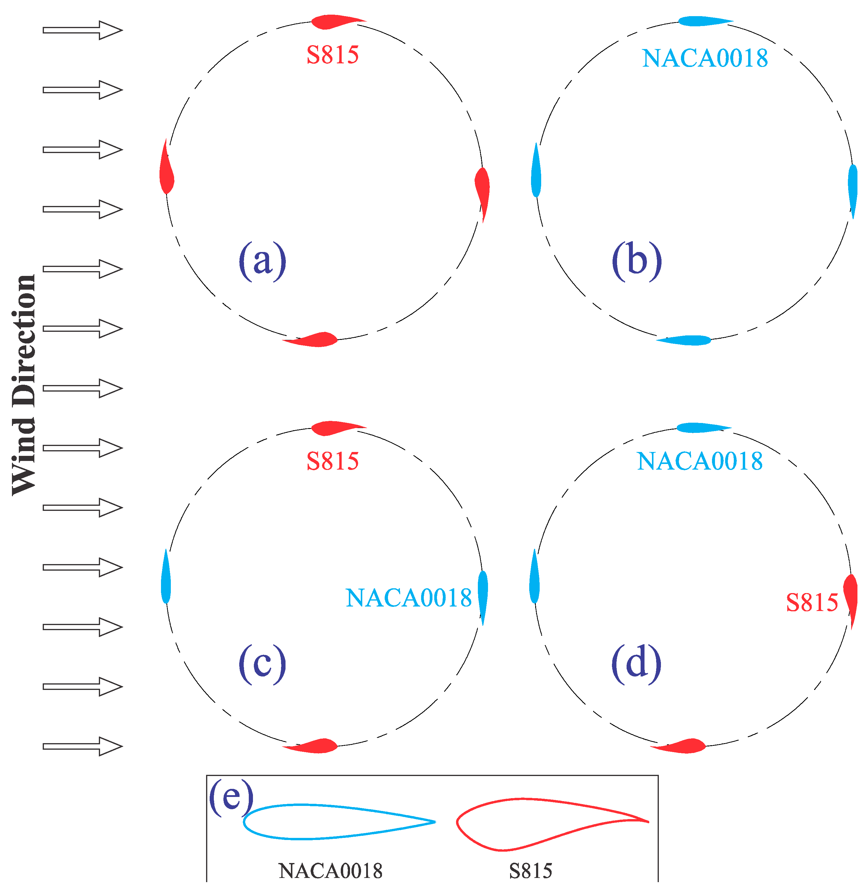
3.1. Numerical Domain

The numerical domain and boundary conditions are depicted in Figure 2 [53]. Two domains, rotating and fixed domains, are connected by an interface boundary condition. The rotating domain rotates inside the fixed domain via the sliding mesh technique for computing the power coefficient. The selected numerical domain can predict the performance of wind turbines, which is evaluated in the validation section. Figure 2b displays NSA-1 as an example in two rotation angles, Δθ of 0° and 45° [53]. Note that VAWT blades at Δθ of 0° and 45° are marked with gray and black, respectively. In Figure 2, D is the rotor diameter. The airfoils of the rotor have zero angles with respect to the rotor; that means the chord lines of airfoils are tangential to the circular border of the rotor.

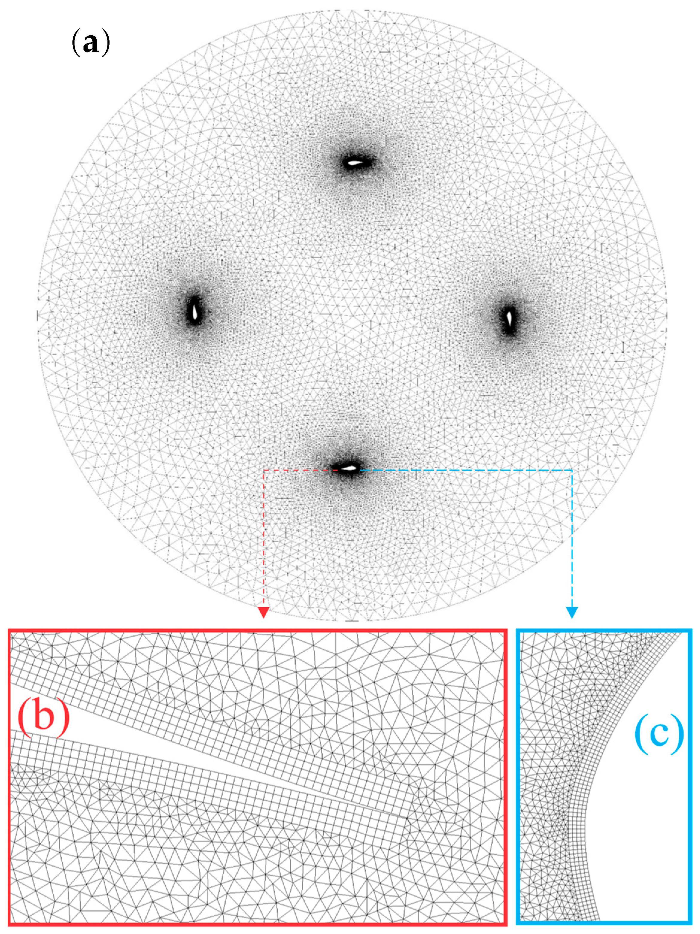
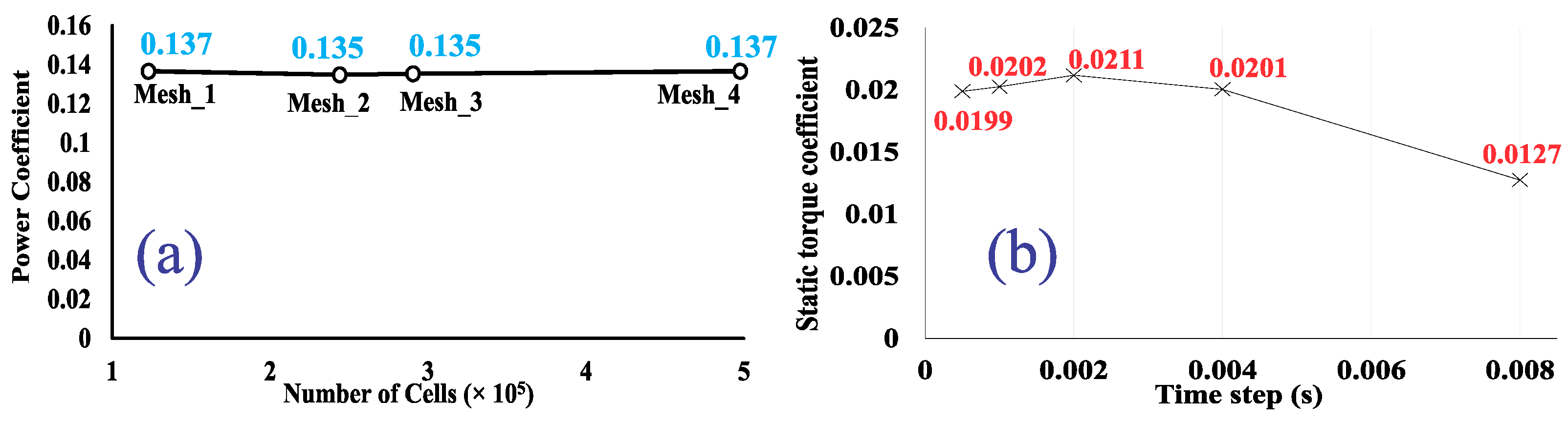
3.2. Mesh and Timestep Independency

Due to the type of study, 2D simulations are used (Figure 3a). Structural meshes are applied for the boundary layers while the rest of the domain is covered by triangular cells. Figure 3b,c show the four layers of the Cartesian mesh as a boundary layer around the S815 airfoil; the other airfoils have the same boundary layer meshes. The quadrilateral boundary layer cells have a height of 4 × 10⁻⁵ m for the first layer. This mesh has orthogonal quality greater than 0.2, and all of the boundary layer cells have orthogonality equal to one. The maximum wall y+ is less than four in all cases.
For an appropriate mesh, mesh independency analysis is carried out for the power coefficient (Figure 4a). The results are consistent for meshes denser than mesh_2 for all cases. Therefore, mesh_2 with 2.4 × 10⁵ cells is used, which results in low computational costs. For the denser meshes, CP deviation from mesh_2 is less than 1.5%.
Two-time step values are considered for dynamic and static simulations. For the dynamic simulation, the value of the time step was based on 0.5° of the rotor rotation. It means that, by considering the mentioned rotational speed of VAWTs (ω = 76 rad/s), the time step is equal to 1.1482 × 10⁻⁴ s. Therefore, it agrees with the Courant–Friedrichs–Lewy (CFL) criteria, as mentioned by Trivellat et al. [54] for all of the studied tip speed ratios (TSRs) in this work. It should be noted that the value of the mentioned CFL number depends on freestream velocity. Therefore, for every TSR, the value of the CFL number is different from others and should be evaluated. However, according to the CFL of Equation (1), if the CFL number for the highest freestream velocity satisfies our criteria for all other cases, CFL criteria will be fulfilled. Therefore, the mentioned CFL criteria are checked for the highest inlet wind speed, presenting the highest CFL number in this study as follows:
CFL ( Δ α ) = R g · Δ α Δ x ( 1 + 1   R g · ω V ) = 0.1 .
where R g is 1.18 m, V is 29.9 m/s, Δα is 0.5°, and Δx is 0.12 m. The calculated CFL number for the worst case is about 0.1, lower than the theoretically allowable limit, which was 0.5. Therefore, this time step is suitable for all considered TSRs of this dynamic simulation.
To select the appropriate time step value for the static simulation, static torque coefficient independency is checked for different time steps; then, the biggest time step, through which the results are independent, is employed. According to Figure 4, for the time step of 0.004 (s), the results are independent of the time step value. The static torque coefficients for the smaller time steps deviate less than 1%.

3.3. Solution Method
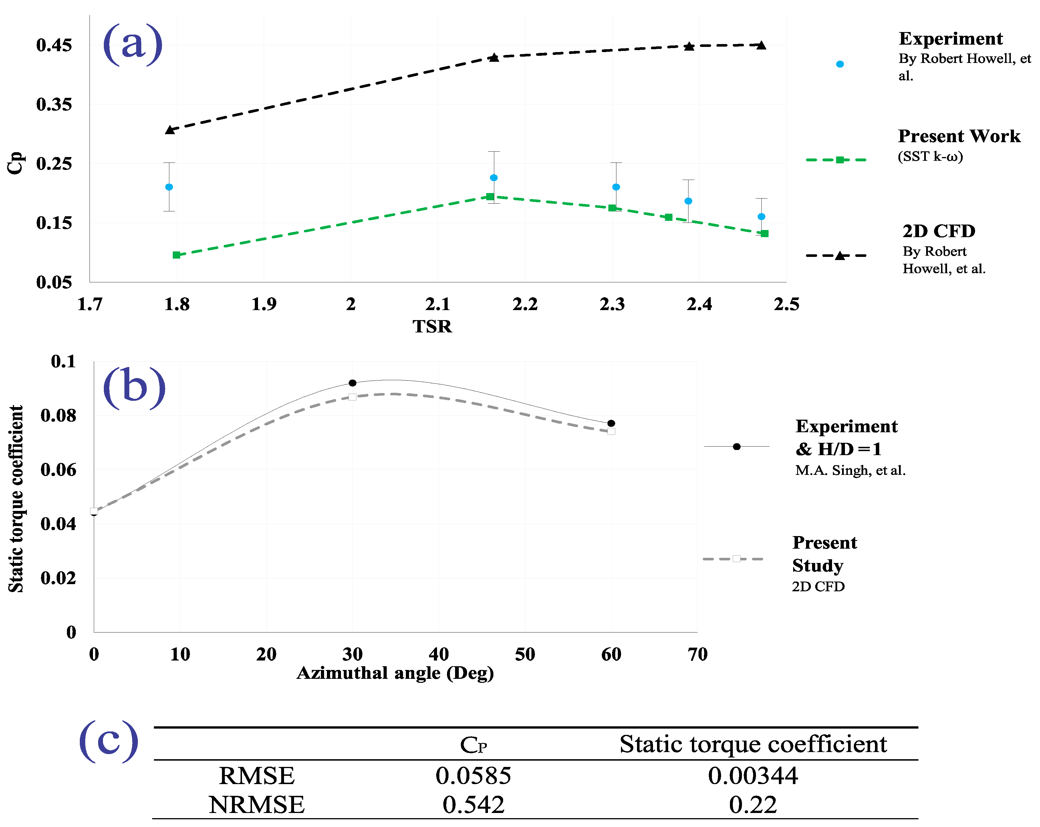
The continuity and 2D Navier–Stokes equations are solved for both dynamic and static simulations. Transient time dependency is used for both of them. The solvers are pressure based for both simulations. For the dynamic simulations, the rotating domain has a rotational velocity of the rotor. For the static simulation, the rotor zone does not have rotational speed and is fixed at a desirable angle. Boundary conditions are presented in Section 3.1. The pressure and velocity in both simulations are coupled together. For discretization, explicit second order is used for spatial discretization of both dynamic and static simulation. A semi-implicit second order is used for temporal discretization in both simulations. The Reynolds number based on the chord length ( Re C = U   . C ν ) is more than 57,000 for all of the cases. According to the value of the Reynolds number and the flow behavior close to the boundary layer and far from it, k-ω SST is used as a turbulence model [55].
To find the power coefficient of VAWTs, initially, the torque coefficient ( C T ) is measured; then, using the tip speed ratio equation ( λ = C P C T ) [13], the power coefficient is obtained [13]. Hybrid initialization is used for initializing the domain. For analyzing the self-starting ability of different VAWTs, the rotor is fixed at rotational angles (Δθ) ranging from 0° to 360° with a step angle of 10°. The calculated torque coefficient is the static torque coefficient. A higher static torque coefficient represents better self-starting ability of the VAWT.

3.4. Validation

Since the self-starting ability is considered for the static simulations, and the power coefficient is targeted for the dynamic simulations, this section presents the validation of the static and dynamic simulations separately.
For dynamic simulation, the results are validated by the experimental and numerical results of Howell et al. [56]. The turbulence model of their numerical simulation was k-ϵ RNG. According to Figure 5, the current 2D simulation agrees with the experimental data, in particular for TSR > 2.1, which is one of the assumptions for the current study.
For static simulation, numerical static torque coefficients or self-starting abilities are compared with the experimental results of Singh et al. [57] when H/D equals 1 (Figure 5). The maximum torque coefficient discrepancy for the mentioned range of the azimuthal angle is almost 0.005. Therefore, the current method will yield proper results.
Root mean square error (RMSE) and normalized RMSE (NRMSE) [58] for the dynamic validation (Figure 5a) and static validation (Figure 5b) are shown in Figure 5c. NRMSEs of dynamic and static simulations are less than 0.6 and 0.3, respectively, showing an acceptable validation [59].

4. Results and Discussion

Two existing standard turbines (HT-S815 and HT-NACA0018) and two novel turbines (NSA-1 and NSA-2) are compared for their performance based on the extracted power coefficients and the self-starting abilities in this section. Additionally, the vorticity contours of novel VAWTs at different angles are provided.

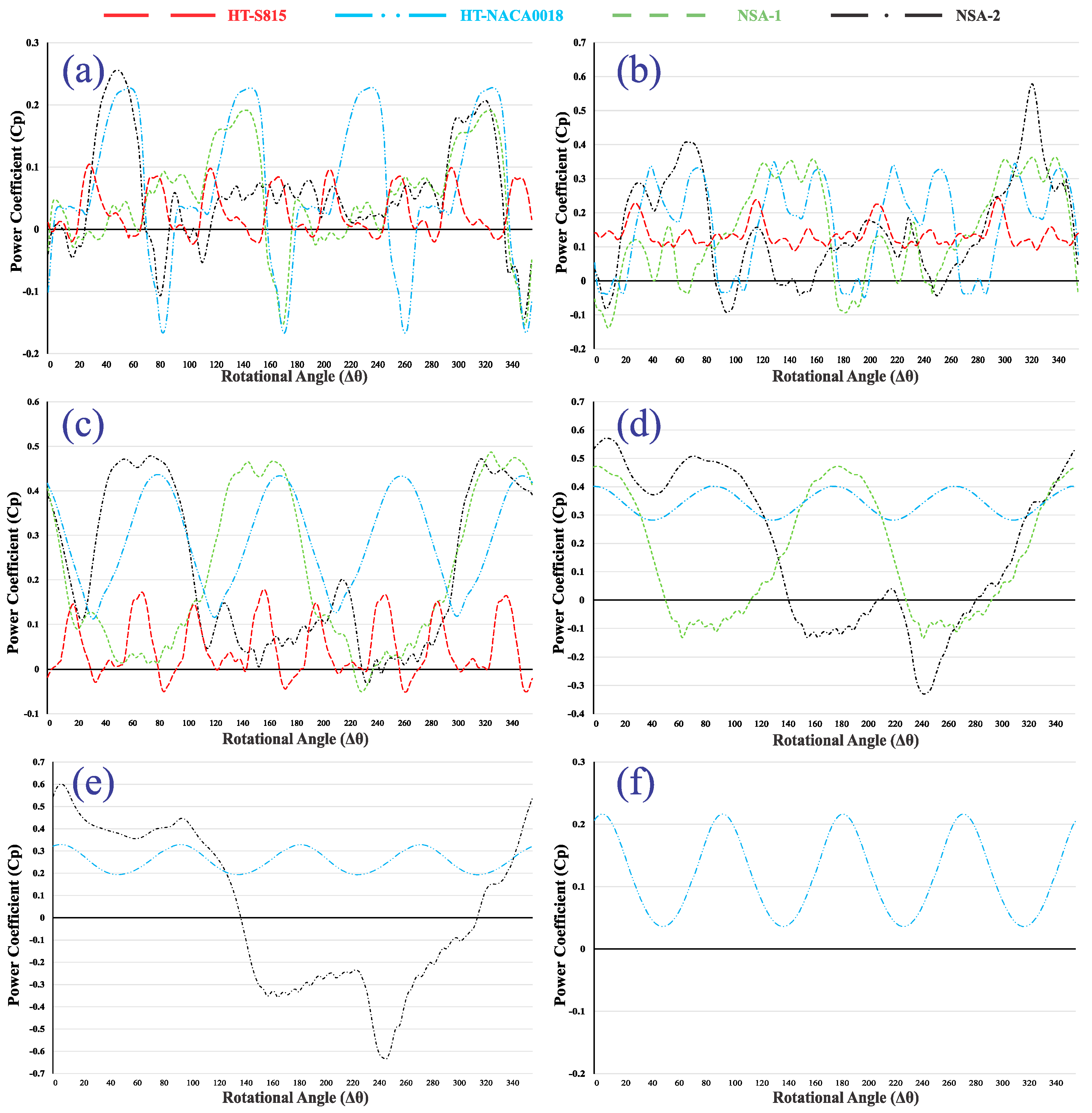
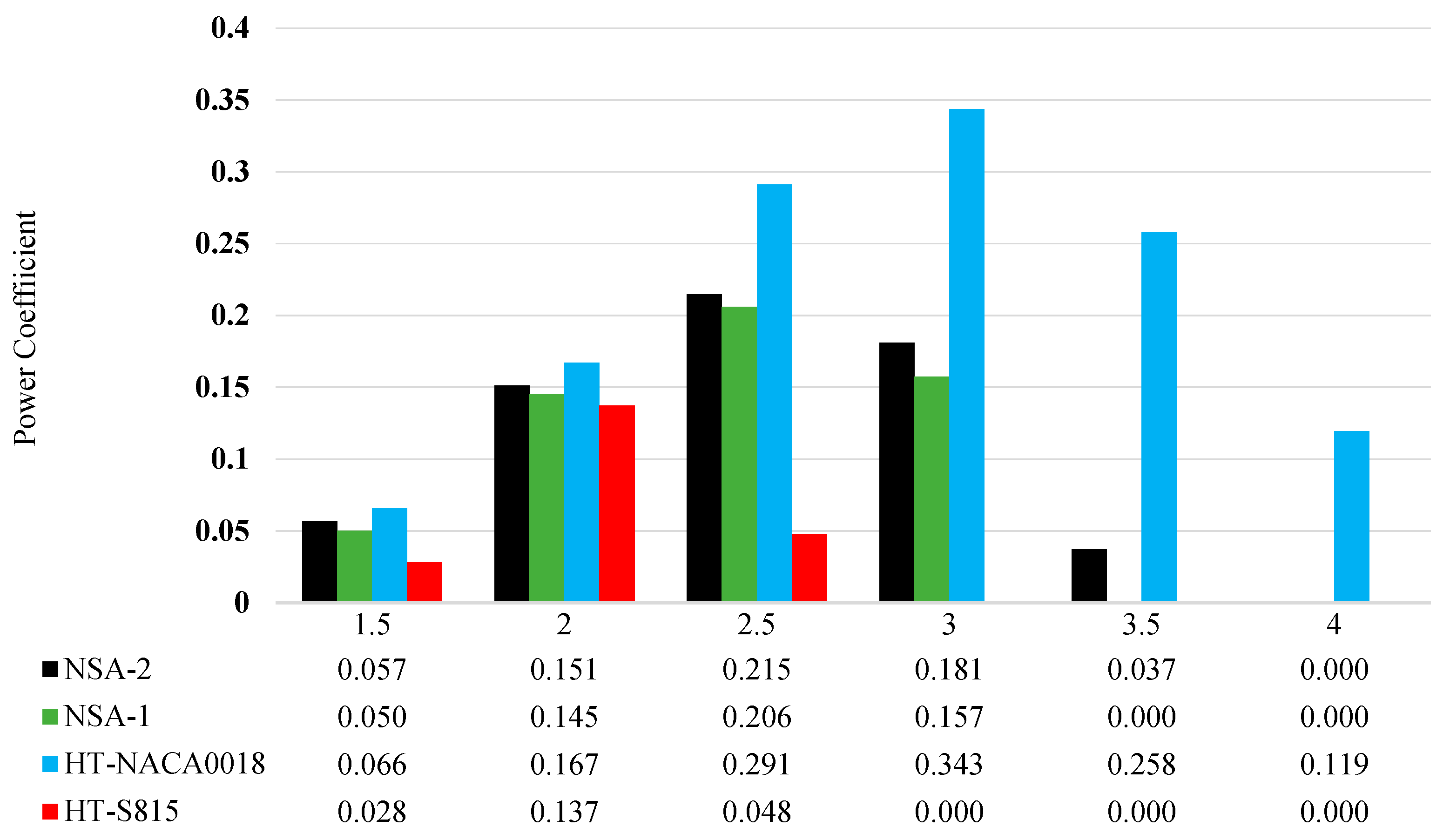
4.1. Power Production

The power coefficients of four types of turbines are displayed in Figure 6 for different TSRs from 1.5 to 4. In TSRs higher than 4, all analyzed VAWTs cannot produce power. Since symmetric blades have higher power coefficients than non-symmetric blades, it is predictable that the HT-NACA0018 turbine produces power in the broader range of TSRs, while the HT-S815 turbine produces lower power within a small range of TSRs. NSA-2 extracts power in a broader range of TSRs compared to other VAWTs and approximately performs like a VAWT with symmetric airfoils in terms of power extraction range. Apart from NSA-2, NSA-1 produces power in a broader range of wind velocity than a VAWT with cambered airfoils. For TSR > 3, NSA-1 and HT-S815 turbines cannot generate power, and their power coefficient is almost zero (not shown in Figure 6). In other TSRs, the power coefficient of NSA-2 is bigger than that of NSA-1.
In TSR = 1.5, Figure 6a shows that due to the type of airfoils and their placements, VAWTs have a different number of repeated cycles in one rotation. HT-NACA0018 has four of them, and NSA-1 has two of them. Nevertheless, NSA-2 does not have a repeated cycle in 360°. Therefore, NSA-2 has the maximum Cp in one rotation compared to other VAWTs. HT-NACA0018 experiences the highest and lowest Cp in this TSR. Although HT-NACA0018 yields the lowest Cp four times in one rotation, it has the highest Cp with the same number of repeats. Maximum Cp is higher than the minimum in terms of value, so HT-NACA0018 has the highest average Cp in this TSR. For NSA-1, the maximum Cp is lower than HT-NACA0018 and NSA-2. It happens two times, and also its lowest Cp is lower than NSA-2 and higher than HT-NACA0018. The maximum Cp of HT-S815 is lower than half of the highest Cp of NSA-2 and HT-NACA0018.
In TSR = 2 (Figure 6b), NSA-2 has the highest Cp, about 1.65 times higher than that of HT-NACA0018. HT-NACA0018 in about 240° of a cycle has a power coefficient close to its highest, and also its lowest Cp is close to zero and higher than those of NSA-2 and NSA-1. NSA-1 has the highest Cp close to HT-NACA0018, and at 160°, its Cp is about half of its maximum. HT-S815 has the lowest oscillation, and its Cp is always between 0.1 and 0.23, roughly about half of the other VAWTs’ maximum values.
In TSR = 2.5 (Figure 6c), NSA-2 and NSA-1 have the highest Cp. Additionally, a similar pattern and Cp variation can be seen when their power coefficient is not as high as their maximum value. HT-NACA0018 has a maximum Cp lower than NSA-1 and NSA-2. HT-S815 has the lowest range of power coefficient.
In TSR = 3 (Figure 6d), the average power coefficient of HT-S815 is zero; therefore, it is not plotted. Unlike NSA-1 and NSA-2, HT-NACA0018 does not have a negative power coefficient in this TSR, and its fluctuation is slight and varies between 0.3 and 0.4. NSA-2 has the highest and lowest Cp compared to other VAWTs. NSA-2’s highest power coefficient is roughly equal to that of NSA-1. In TSR = 3.5 (Figure 6e), like HT-S815, NSA-1 does not produce power, so it is not shown. Again, HT-NACA0018 has a slight fluctuation, and its Cp varies between 0.2 and 0.32. If signs of power coefficients are ignored, the minimum Cp of NSA-2 will be bigger than its maximum. Finally, in TSR = 4 (Figure 6f), only HT-NACA0018 can produce power and oscillates between 0.04 and 0.22.
An interesting point in Figure 6 is the fact that when novel rotors reach their maximum power coefficients, they produce power even higher than HT-NACA0018. In other words, novel wind turbines have higher maximum power coefficients than HT-NACA0018. Therefore, it might be concluded that the placement of S815 near NACA0018 in NSA-2 has a beneficial impact on the power output. Another positive aspect observed in Figure 6 is reducing power coefficient fluctuations in one rotation of novel rotors.
Based on Figure 7, NSA-2 has outperformed NSA-1 in all TSRs; when similar airfoils are close to each other, the power production is enhanced. The power coefficient of NSA-2 in TSR of 1.5 is about 104% more than that of HT-S815, which is just 13.6% less than HT-NACA0018. The highest average power coefficients of all types of turbines have been found in the TSR of 2.5 (Figure 8b). Based on TSR values, NSA-1 and NSA-2 have their highest power coefficients when TSR equals 2.5; the TSR of 2.5 is considered as the design TSR for the novel turbines. At the TSR of 2, the power coefficient of NSA-2 (0.151) is about 9.6% lower than the power coefficient of HT-NACA0018 (0.167); HT-NACA0018 is the best turbine in terms of power production in TSR of 2. In design TSR (TSR = 2.5), NSA-2 has increased the power coefficient about 4.5 times more than that of HT-S815. Therefore, this novel VAWT can reduce the power coefficient difference between HT-NACA0018 and HT-S815 significantly.
The average of produced Cp, based on all TSRs from 1.5 to 4, can be seen in Figure 8a. NSA-2 can produce about 15% more power than NSA-1. Therefore, NSA-2 is a suitable option for power extraction and can produce 205.7% more power than HT-S815. Nevertheless, this turbine has a power coefficient slightly higher than half of that of HT-NACA0018.
For each TSR, the power coefficients of all analyzed VAWTs from Figure 7 are averaged and plotted in Figure 8b. The TSR with the maximum average power coefficient (0.19) of VAWTs is 2.5, which is the same as the design TSR of novel turbines.

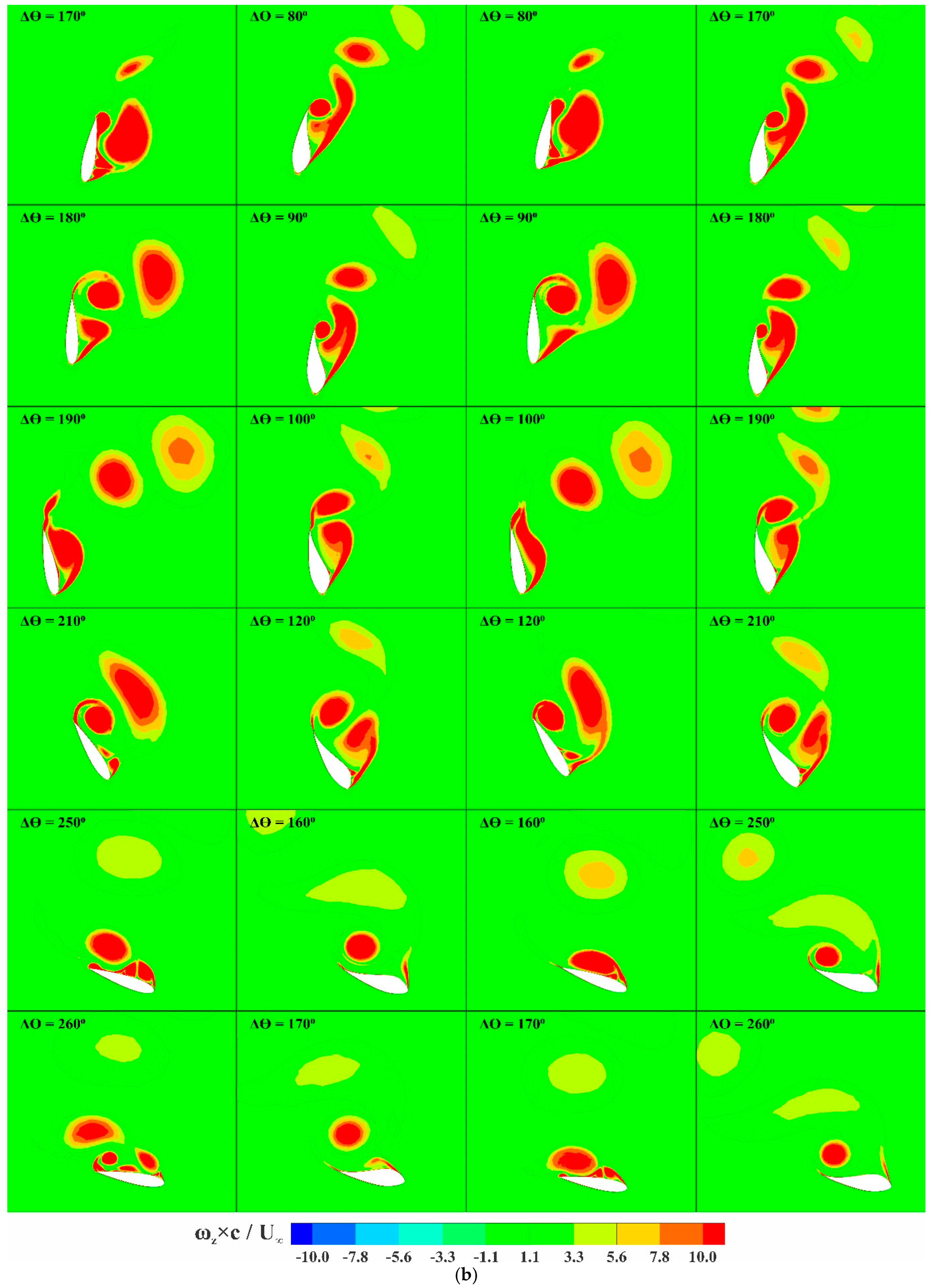
4.2. Dynamic Stall Phenomena

For NSA-1, when the NACA0018 is in front of the wind, the vorticity contours are shown in the first column of Figure 9. In this condition, the first leading edge vortex (LEV) is developing at Δθ = 140°. Before Δθ = 170°, the first LEV is fully developed and is separated from the pressure side of the airfoil. After the first LEV separation, at Δθ = 170°, the first trailing edge vortex (TEV) is visible, which helps to decrease lift coefficient while the separated first LEV sheds to the downstream. At Δθ = 180°, the first TEV is separating, and the second LEV is developed. This second LEV is ready to separate when Δθ = 190°. After that, small vortices generate and shed rapidly downstream, which is visible at Δθ = 260°. These small vortices do not have enough time to develop, and then they do not cause significant load changes. For TSR of 1.5, Figure 6a shows that the NACA0018 airfoil in NSA-1 results in a Cp increase after Δθ = 110° and then after the LEV generation, a sudden Cp decrease is observed after Δθ = 140°. This sudden Cp fall affects the overall performance of NSA-1. For the NSA-1 turbine, when the S815 airfoil is located in front of the wind, the vorticity contours are shown in the second column of Figure 9. The S815 airfoil is an airfoil with a high camber. The first LEV is generated at a low angle of Δθ = 30°. The first LEV is developed at Δθ = 50° when the second LEV is ready to complete. The LEV is a low-pressure vortex that causes lift production. The first LEV delay for NACA0018 results in a strong vortex. Although dynamic stall is observed for S815, it did not cause significant power reduction after LEV separation (Figure 6a). Thus, the average Cp does not vary significantly when S815 is in front of the wind. It can be concluded that since S815 is not a power extraction airfoil, the dynamic stall related to S815 does not change the domain of power coefficient variation significantly.
The vortical structures of NACA0018 and S815 for different arrangements in the NSA-2 turbine are shown in the last two columns of Figure 9. The interesting point is that their vortical structure around airfoils is very close to that of NSA-1. Changing the location of NACA0018 results in varying the maximum and minimum Cp values for each turbine, as shown in Figure 9. The combination of the loads on each blade results in different power extraction. According to Figure 6 and Figure 9, dynamic stall phenomena are more effective in lower TSRs which agrees with the work of Yen and Ahmed [45].

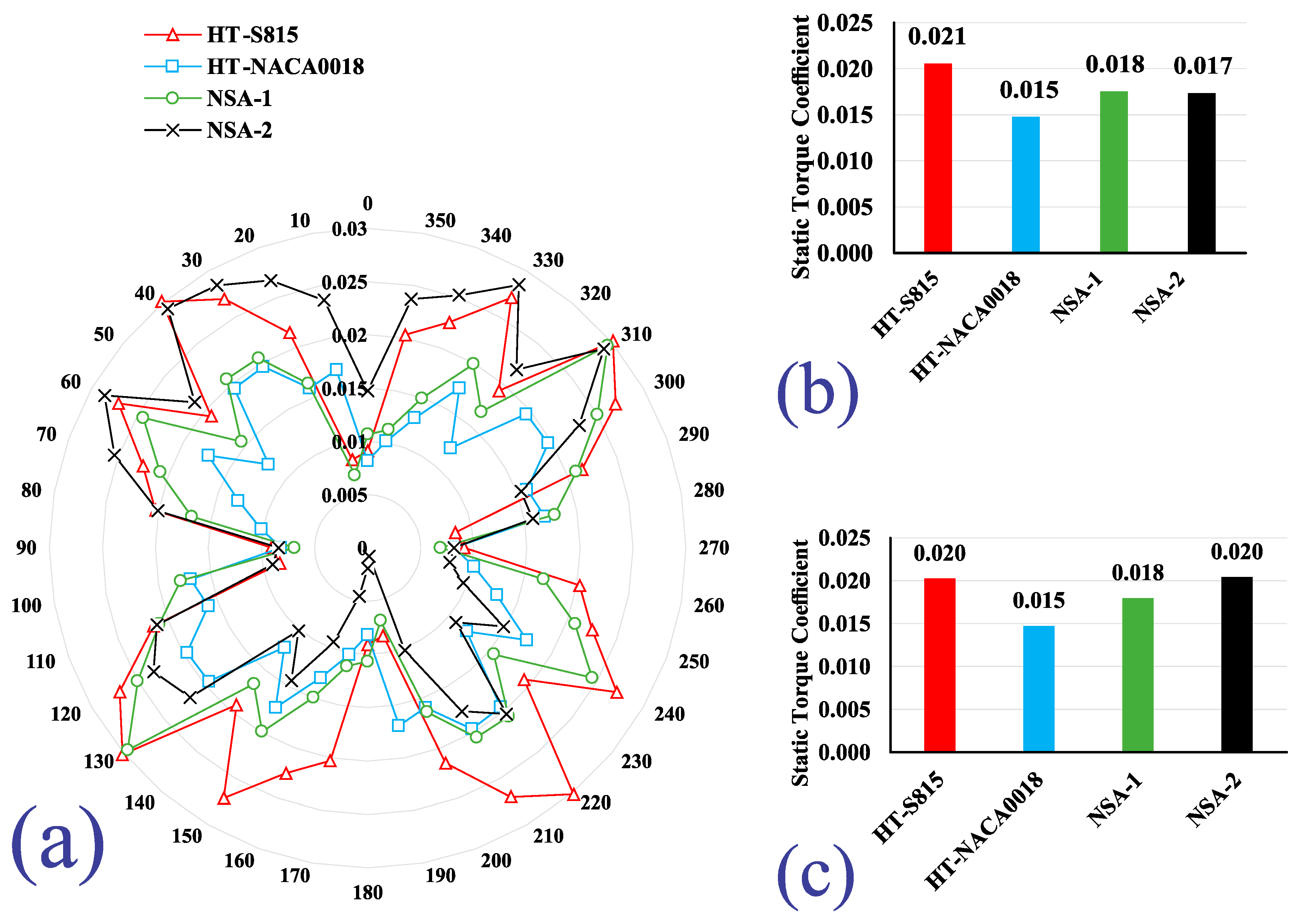
4.3. Self-Starting Ability

The static torque coefficients of all turbines for one cycle are plotted in Figure 10a. Based on Figure 10a, the most conventional turbines, including HT-NACA0018 and HT-S815, have the lowest and highest self-starting abilities, respectively, in almost all azimuthal angles. The novel NSA-2 turbine has the highest self-starting ability at almost all angles when −90° < ϴ < +90°. Severe fluctuations can be seen in the static torque coefficient curve of NSA-2 in such a way that, in half of the cycle, it is close to the curve of HT-NACA0018; in the other half, NSA-2 has the highest self-starting ability. NSA-1 in almost all angles has self-starting ability between HT-NACA0018 and HT-S815. The overall pattern of static torque coefficients in the whole cycle is almost the same for all rotors.
The extracted information from Figure 10b agrees well with the other studies that a high static torque coefficient is one of the attributes of non-symmetric blades [13]. That is why the HT-S815 turbine has the highest CT (Figure 10b). NSA-1 and NSA-2 turbines have average static torque coefficients of about 85% of the HT-S815 VAWT; their coefficients are 18% more than HT-NACA0018.
In Figure 10c, notably, the NSA-2 turbine with two S815 and two NACA0018 blades has the best CT within 66.7% of one cycle (360° except for 140° < ϴ < 260°) and behaves similar to the rotor with non-symmetric airfoils (HT-S815). This is an important advantage for the NSA-2 turbine due to the importance of the self-starting behavior of VAWTs at different quadrants [5]. The two S815 blades are in front of the wind flow within the mentioned range to generate a high positive torque. However, in another half of the turbine, it has NACA0018 blades with a lower negative static torque coefficient compared to S815 at the same positions. Hence, these NACA0018 blades have a lower negative impact on the VAWT self-starting in comparison with S815. Based on the explained reason, the average CT of NSA-2 is more than that of HT-S815 within the mentioned range. NSA-2 has better self-starting than HT-NACA0018 by about 13.3% in one cycle. Additionally, according to its power coefficient in TSR of 2, it can be a good choice for this TSR with proper self-starting ability and power coefficient.

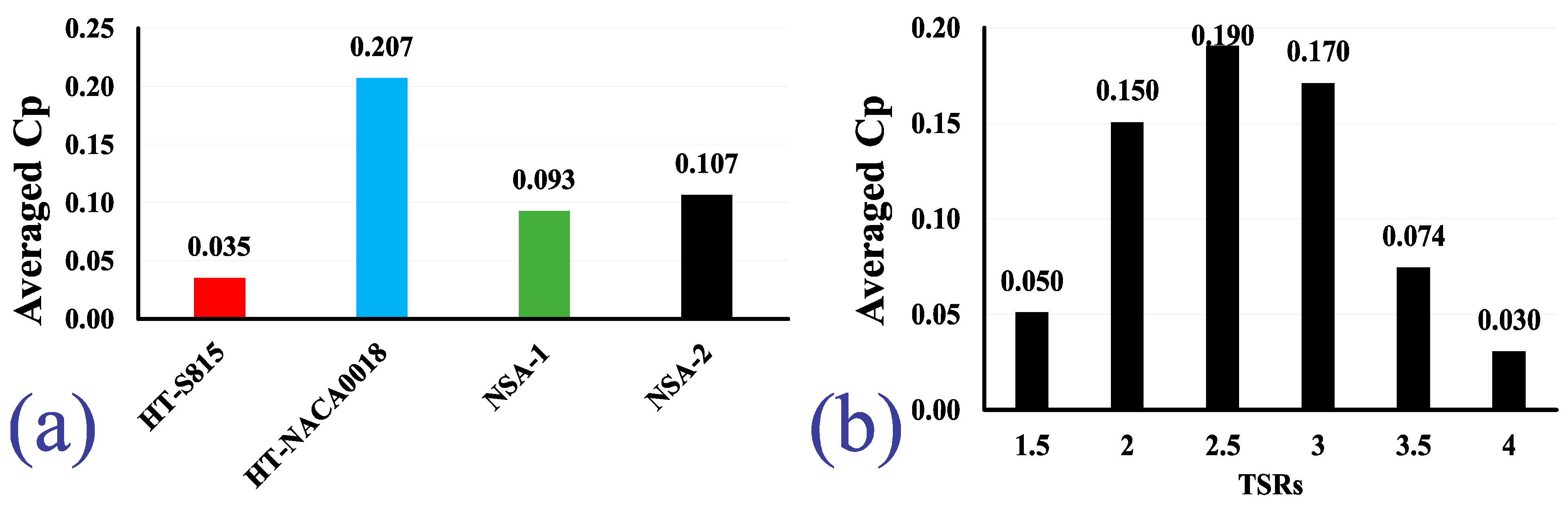
4.4. Overall Performance Analysis

The performance analysis is summarized in Table 2. HT-S815 with the highest self-starting ability has a self-starting of 40% higher than that of HT-NACA0018. On the other hand, HT-NACA0018 has a power coefficient of about 506% higher than the power coefficient of HT-S815. A preferred turbine is one with a high-power extraction and self-starting capability. NSA-2 has a self-starting ability the same as HT-S815 in about 66.7% of one cycle. For the self-starting ability, if the wind turbine can be held at suitable angles (−100° < ϴ < 140°), NSA-2 is a desirable turbine. Moreover, this novel VAWT, NSA-2, in one cycle (360 ° ) has a self-starting of 13.3% higher than HT-NACA0018.
Although NSA-1 and NSA-2 can increase the power coefficient up to 329.1% and 347.9% compared to the power coefficient of HT-S815, in design TSR, their power coefficient is only 29.2% and 26.1% lower than the power coefficient of HT-NACA0018, respectively, while the power coefficient of HT-S815 is 83.5% lower than that of HT-NACA0018. On the other hand, Lin et al. [34] showed 16.4% power improvement without considering the self-starting ability by modifying the trailing edge to a wave-like form. Since the current study is simple and more cost-effective and its improvement is also higher than the study of Lin et al., it can be concluded that the current improvement is a remarkable achievement.
The results can be compared with a hybrid rotor as another novel work, such as a combination of Savonius and Darrieus rotors that has become popular recently. However, although these hybrid rotors can increase the self-starting ability compared with the Darrieus rotor, their static torque coefficient is less than that of Savonius rotors. Additionally, the main drawback of the hybrid rotors is their power coefficient, which is even less than that of drag-based VAWTs by approximately a factor of 4.
The simplicity of the novel turbine, NSA-2, keeps the capital cost of the turbine low while the overall performance of the turbine is improved. Since no advanced control system is added, the turbine is user-friendly. Then, this novel turbine is recommended for remote areas as well as for disadvantaged communities. It can be used for either off-grid or on-grid systems.

5. Conclusions

The computational fluid dynamics (CFD) method was employed to investigate the performance of two novel vertical axis wind turbines. The power extraction of the novel turbines was studied in different TSRs from 1.5 to 4. In addition, the self-starting capability of the turbines was evaluated.
There is always a tradeoff between the power coefficient and the self-starting ability of a VAWT. The self-starting ability of HT-S815 was 40% higher than that of HT-NACA0018 while the power coefficient of HT-NACA0018 was 506% more than the power coefficient of HT-S815. The novel turbines should decrease the mention differences between these two conventional turbines. Although two novel turbines have been proposed, NSA-2 in all TSRs outperformed NSA-1 in terms of power coefficient. The highest power coefficients of novel turbines happened in a TSR of 2.5. This TSR is considered as the design TSR. With the aid of NSA-2, the power coefficient of this novel turbine was 347.9% higher than the power coefficient of HT-S815. On the other hand, the self-starting ability of NSA-2 was 13.3% higher than that of HT-NACA0018. For the azimuthal angles between 0°–140° and 260°–360°, NSA-2 surpassed our expectations; the mean static torque coefficient of NSA-2 was equal to that of HT-S815 with four non-symmetric airfoils. Given the mentioned aspect, it would be fascinating if NSA-2 was fixed within this range of mentioned azimuthal angle at the beginning of the rotation.

Author Contributions

Methodology, validation, and discussion, S.M.D.; supervision, K.G., discussion, review, and editing, S.M.D., K.G., A.A.-H. and J.N. All authors have read and agreed to the published version of the manuscript.

Funding

This research received no external funding.

Institutional Review Board Statement

Not applicable.

Informed Consent Statement

Not applicable.

Data Availability Statement

Not applicable.

Conflicts of Interest

The authors declare no conflict of interest.

Nomenclature

Parameters
RgRotating domain radius m
ΔxSpatial discretization m
CPPower coefficient -
CTTorque coefficient -
RecReynolds based on chord length -
UFreestream velocitym/s
CChord length m
Subscripts and abbreviations
CFL ( Δ α ) Courant–Friedrichs–Lewy number
VAWT Vertical axis wind turbine
NSANon-Similar Airfoil
HTH-type
Greek letters
Δ α Azimuthal angle changes in a time stepRad
Λ Rotating grid tip speed ratio-
λ Tip speed ratio (TSR)-
ν Kinematic viscosity m 2 / s
θ Wind turbine azimuthal angle Degree

References

  1. Koroneos, C.; Spachos, T.; Moussiopoulos, N. Exergy analysis of renewable energy sources. Renew. Energy 2003, 28, 295–310. [Google Scholar] [CrossRef]
  2. Jin, X.; Zhao, G.; Gao, K.; Ju, W. Darrieus vertical axis wind turbine: Basic research methods. Renew. Sustain. Energy Rev. 2015, 42, 212–225. [Google Scholar] [CrossRef]
  3. Elsakka, M.M.; Ingham, D.B.; Ma, L.; Pourkashanian, M. CFD analysis of the angle of attack for a vertical axis wind turbine blade. Energy Convers. Manag. 2019, 182, 154–165. [Google Scholar] [CrossRef]
  4. Li, Y.; Zhao, S.; Tagawa, K.; Feng, F. Starting performance effect of a truncated-cone-shaped wind gathering device on small-scale straight-bladed vertical axis wind turbine. Energy Convers. Manag. 2018, 167, 70–80. [Google Scholar] [CrossRef]
  5. Dominy, R.G.; Lunt, P.; Bickerdyke, A.; Dominy, J. Self-starting capability of a Darrieus turbine. Proc. Inst. Mech. Eng. Part A J. Power Energy 2007, 221, 111–120. [Google Scholar] [CrossRef] [Green Version]
  6. Li, Q.; Maeda, T.; Kamada, Y.; Murata, J.; Furukawa, K.; Yamamoto, M. Effect of number of blades on aerodynamic forces on a straight-bladed Vertical Axis Wind Turbine. Energy 2015, 90, 784–795. [Google Scholar] [CrossRef]
  7. Beri, H.; Yao, Y. Numerical simulation of unsteady flow to show self-starting of vertical axis wind turbine using fluent. J. Appl. Sci. 2011, 11, 962–970. [Google Scholar] [CrossRef] [Green Version]
  8. Danao, L.A.; Qin, N.; Howell, R. A numerical study of blade thickness and camber effects on vertical axis wind turbines. Proc. Inst. Mech. Eng. Part A J. Power Energy 2012, 226, 867–881. [Google Scholar] [CrossRef]
  9. Asr, M.T.; Nezhad, E.Z.; Mustapha, F.; Wiriadidjaja, S. Study on start-up characteristics of H-Darrieus vertical axis wind turbines comprising NACA 4-digit series blade airfoils. Energy 2016, 112, 528–537. [Google Scholar] [CrossRef]
  10. Chen, J.; Chen, L.; Xu, H.; Yang, H.; Ye, C.; Liu, D. Performance improvement of a vertical axis wind turbine by comprehensive assessment of an airfoil family. Energy 2016, 114, 318–331. [Google Scholar] [CrossRef]
  11. Hara, Y.; Kawamura, T.; Akimoto, H.; Tanaka, K.; Nakamura, T.; Mizumukai, K. Predicting double-blade vertical axis wind turbine performance by a quadruple-multiple streamtube model. Int. J. Fluid Mach. Syst. 2014, 7, 16–27. [Google Scholar] [CrossRef] [Green Version]
  12. Alaimo, A.; Esposito, A.; Messineo, A.; Orlando, C.; Tumino, D. 3D CFD analysis of a vertical axis wind turbine. Energies 2015, 8, 3013–3033. [Google Scholar] [CrossRef] [Green Version]
  13. Bhuyan, S.; Biswas, A. Investigations on self-starting and performance characteristics of simple H and hybrid H-Savonius vertical axis wind rotors. Energy Convers. Manag. 2014, 87, 859–867. [Google Scholar] [CrossRef]
  14. Pan, H.; Li, H.; Zhang, T.; Laghari, A.A.; Zhang, Z.; Yuan, Y.; Qian, B. A portable renewable wind energy harvesting system integrated S-rotor and H-rotor for self-powered applications in high-speed railway tunnels. Energy Convers. Manag. 2019, 196, 56–68. [Google Scholar] [CrossRef]
  15. Hosseini, A.; Goudarzi, N. Design and CFD study of a hybrid vertical-axis wind turbine by employing a combined Bach-type and H-Darrieus rotor systems. Energy Convers. Manag. 2019, 189, 49–59. [Google Scholar] [CrossRef]
  16. Scungio, M.; Arpino, F.; Profili, M.; Rotondi, M.; Focanti, V.; Bedon, G. Wind tunnel testing of scaled models of a newly developed Darrieus-style vertical axis wind turbine. In Proceedings of the European Wind Energy Association Annual Conference and Exhibition 2015, Paris, France, 17–20 November 2015; Volume 130, pp. 60–70. [Google Scholar] [CrossRef]
  17. Arpino, F.; Scungio, M.; Cortellessa, G. Numerical performance assessment of an innovative Darrieus-style vertical axis wind turbine with auxiliary straight blades. Energy Convers. Manag. 2018, 171, 769–777. [Google Scholar] [CrossRef]
  18. Li, Q.; Maeda, T.; Kamada, Y.; Shimizu, K.; Ogasawara, T.; Nakai, A.; Kasuya, T. Effect of rotor aspect ratio and solidity on a straight-bladed vertical axis wind turbine in three-dimensional analysis by the panel method. Energy 2017, 121, 1–9. [Google Scholar] [CrossRef]
  19. Wang, Y.; Shen, S.; Li, G.; Huang, D.; Zheng, Z. Investigation on aerodynamic performance of vertical axis wind turbine with different series airfoil shapes. Renew. Energy 2018, 126, 801–818. [Google Scholar] [CrossRef]
  20. Zhong, J.; Li, J.; Guo, P.; Wang, Y. Dynamic stall control on a vertical axis wind turbine aerofoil using leading-edge rod. Energy 2019, 174, 246–260. [Google Scholar] [CrossRef]
  21. Xu, W.; Li, G.; Wang, F.; Li, Y. High-resolution numerical investigation into the effects of winglet on the aerodynamic performance for a three-dimensional vertical axis wind turbine. Energy Convers. Manag. 2020, 205, 112333. [Google Scholar] [CrossRef]
  22. Yang, Y.; Guo, Z.; Song, Q.; Zhang, Y.; Li, Q. Effect of blade pitch angle on the aerodynamic characteristics of a straight-bladed vertical axis wind turbine based on experiments and simulations. Energies 2018, 11, 1514. [Google Scholar] [CrossRef] [Green Version]
  23. Zhu, H.; Hao, W.; Li, C.; Ding, Q. Numerical study of effect of solidity on vertical axis wind turbine with Gurney flap. J. Wind Eng. Ind. Aerodyn. 2019, 186, 17–31. [Google Scholar] [CrossRef]
  24. Abdalrahman, G.; Melek, W.; Lien, F.S. Pitch angle control for a small-scale Darrieus vertical axis wind turbine with straight blades (H-Type VAWT). Renew. Energy 2017, 114, 1353–1362. [Google Scholar] [CrossRef] [Green Version]
  25. Guo, J.; Zeng, P.; Lei, L. Performance of a straight-bladed vertical axis wind turbine with inclined pitch axes by wind tunnel experiments. Energy 2019, 174, 553–561. [Google Scholar] [CrossRef]
  26. Ferreira, C.S.; Geurts, B. Aerofoil optimization for vertical-axis wind turbines. Wind Energy 2015, 18, 1371–1385. [Google Scholar] [CrossRef]
  27. Carrigan, T.J.; Dennis, B.H.; Han, Z.X.; Wang, B.P. Aerodynamic shape optimization of a verticalaxis wind turbine using differential evolution. Wind Turbine Technol. Princ. Des. 2014, 2012, 79–121. [Google Scholar] [CrossRef]
  28. Rezaeiha, A.; Kalkman, I.; Blocken, B. Effect of pitch angle on power performance and aerodynamics of a vertical axis wind turbine. Appl. Energy 2017, 197, 132–150. [Google Scholar] [CrossRef] [Green Version]
  29. Li, Q.; Maeda, T.; Kamada, Y.; Murata, J.; Yamamoto, M.; Ogasawara, T.; Shimizu, K.; Kogaki, T. Study on power performance for straight-bladed vertical axis wind turbine by field and wind tunnel test. Renew. Energy 2016, 90, 291–300. [Google Scholar] [CrossRef]
  30. Roberts, G.D. Omni-Directional Vertical-Axis Wind Turbine. U.S. Patent No. 6,465,899, 15 October 2002. [Google Scholar]
  31. Nobile, R.; Vahdati, M.; Barlow, J.F.; Mewburn-Crook, A. Unsteady flow simulation of a vertical axis augmented wind turbine: A two-dimensional study. J. Wind Eng. Ind. Aerodyn. 2014, 125, 168–179. [Google Scholar] [CrossRef] [Green Version]
  32. Takao, M.; Takita, H.; Saito, Y.; Maeda, T.; Kamada, Y.; Toshimitsu, K. Experimental study of a straight-bladed vertical axis wind turbine with a directed guide vane row. In Proceedings of the ASME 2009 28th International Conference on Ocean, Offshore and Arctic Engineering: OMAE 2009, Honolulu, HI, USA, 31 May–5 June 2009; American Society of Mechanical Engineers: New York, NY, USA, 2009; Volume 4, pp. 1093–1099. [Google Scholar]
  33. Shahizare, B.; Nik-Ghazali, N.; Chong, W.T.; Tabatabaeikia, S.; Izadyar, N.; Esmaeilzadeh, A. Novel investigation of the different Omni-direction-guide-vane angles effects on the urban vertical axis wind turbine output power via three-dimensional numerical simulation. Energy Convers. Manag. 2016, 117, 206–217. [Google Scholar] [CrossRef]
  34. Lin, S.Y.; Lin, Y.Y.; Bai, C.J.; Wang, W.C. Performance analysis of vertical-axis-wind-turbine blade with modified trailing edge through computational fluid dynamics. Renew. Energy 2016, 99, 654–662. [Google Scholar] [CrossRef]
  35. Wang, Z.; Zhuang, M. Leading-edge serrations for performance improvement on a vertical-axis wind turbine at low tip-speed-ratios. Appl. Energy 2017, 208, 1184–1197. [Google Scholar] [CrossRef]
  36. Bianchini, A.; Balduzzi, F.; Di Rosa, D.; Ferrara, G. On the use of Gurney Flaps for the aerodynamic performance augmentation of Darrieus wind turbines. Energy Convers. Manag. 2019, 184, 402–415. [Google Scholar] [CrossRef]
  37. Wang, Y.; Sun, X.; Dong, X.; Zhu, B.; Huang, D.; Zheng, Z. Numerical investigation on aerodynamic performance of a novel vertical axis wind turbine with adaptive blades. Energy Convers. Manag. 2016, 108, 275–286. [Google Scholar] [CrossRef]
  38. Butbul, J.; MacPhee, D.; Beyene, A. The impact of inertial forces on morphing wind turbine blade in vertical axis configuration. Energy Convers. Manag. 2015, 91, 54–62. [Google Scholar] [CrossRef]
  39. Simão Ferreira, C.; Van Kuik, G.; Van Bussel, G.; Scarano, F. Visualization by PIV of dynamic stall on a vertical axis wind turbine. Exp. Fluids 2009, 46, 97–108. [Google Scholar] [CrossRef] [Green Version]
  40. Bakhtiari, E.; Gharali, K.; Chini, S.F. Corrigendum to “Super-hydrophobicity effects on performance of a dynamic wind turbine blade element under yaw loads” (Renewable Energy (2019) 140 (539–551), (S096014811930357X), (10.1016/j.renene.2019.03.052)). Renew. Energy 2020, 147, 2528. [Google Scholar] [CrossRef]
  41. Kobra Gharali, M.G. A PIV study of a low Reynolds number pitch oscillating SD7037 airfoil in dynamic stall with CFD comparison. In Proceedings of the 16th International Symposium on Applications of Laser Techniques to Fluid Mechanics, Lisbon, Portugal, 9–12 July 2012; Volume 14, pp. 9–12. [Google Scholar]
  42. Gharali, K.; Johnson, D.A. Dynamic stall simulation of a pitching airfoil under unsteady freestream velocity. J. Fluids Struct. 2013, 42, 228–244. [Google Scholar] [CrossRef]
  43. Gharali, K.; Johnson, D.A.; Lam, V.; Gu, M. A 2D blade element study of a wind turbine rotor under yaw loads. Wind Eng. 2015, 39, 557–568. [Google Scholar] [CrossRef]
  44. Larsen, J.W.; Nielsen, S.R.K.; Krenk, S. Dynamic stall model for wind turbine airfoils. J. Fluids Struct. 2007, 23, 959–982. [Google Scholar] [CrossRef]
  45. Yen, J.; Ahmed, N.A. Enhancing vertical axis wind turbine by dynamic stall control using synthetic jets. J. Wind Eng. Ind. Aerodyn. 2013, 114, 12–17. [Google Scholar] [CrossRef]
  46. Greenblatt, D.; Schulman, M.; Ben-Harav, A. Vertical axis wind turbine performance enhancement using plasma actuators. Renew. Energy 2012, 37, 345–354. [Google Scholar] [CrossRef]
  47. Wang, Z.; Wang, Y.; Zhuang, M. Improvement of the aerodynamic performance of vertical axis wind turbines with leading-edge serrations and helical blades using CFD and Taguchi method. Energy Convers. Manag. 2018, 177, 107–121. [Google Scholar] [CrossRef]
  48. Wong, K.H.; Chong, W.T.; Sukiman, N.L.; Shiah, Y.C.; Poh, S.C.; Sopian, K.; Wang, W.C. Experimental and simulation investigation into the effects of a flat plate deflector on vertical axis wind turbine. Energy Convers. Manag. 2018, 160, 109–125. [Google Scholar] [CrossRef]
  49. Chong, W.T.; Fazlizan, A.; Poh, S.C.; Pan, K.C.; Hew, W.P.; Hsiao, F.B. The design, simulation and testing of an urban vertical axis wind turbine with the omni-direction-guide-vane. Appl. Energy 2013, 112, 601–609. [Google Scholar] [CrossRef]
  50. Yokoi, T. Vertical Axis Wind Turbine and Wind Turbine Blade. U.S. Patent 10/594,270, 2 August 2007. [Google Scholar]
  51. Maleki Dastjerdi, S.; HormoziNejad, A.; Gharali, K.; Nathwani, J. Numerical investigation of VAWT airfoil shapes on power extraction and self-starting purposes. In Proceedings of the AMMCS 2019; Springer: Waterloo Canada; 2019. [Google Scholar]
  52. Bianchini, A.; Balduzzi, F.; Rainbird, J.M.; Peiró, J.; Graham, J.M.R.; Ferrara, G.; Ferrari, L. On the influence of virtual camber effect on airfoil polars for use in simulations of Darrieus wind turbines. Energy Convers. Manag. 2015, 106, 373–384. [Google Scholar] [CrossRef]
  53. Trivellato, F.; Raciti Castelli, M. On the Courant-Friedrichs-Lewy criterion of rotating grids in 2D vertical-axis wind turbine analysis. Renew. Energy 2014, 62, 53–62. [Google Scholar] [CrossRef]
  54. Roy, S.; Ducoin, A. Unsteady analysis on the instantaneous forces and moment arms acting on a novel Savonius-style wind turbine. Energy Convers. Manag. 2016, 121, 281–296. [Google Scholar] [CrossRef]
  55. Howell, R.; Qin, N.; Edwards, J.; Durrani, N. Wind tunnel and numerical study of a small vertical axis wind turbine. Renew. Energy 2010, 35, 412–422. [Google Scholar] [CrossRef] [Green Version]
  56. Singh, M.A.; Biswas, A.; Misra, R.D. Investigation of self-starting and high rotor solidity on the performance of a three S1210 blade H-type Darrieus rotor. Renew. Energy 2015, 76, 381–387. [Google Scholar] [CrossRef]
  57. Hand, B.; Cashman, A.; Kelly, G. A Low-Order Model for Offshore Floating Vertical Axis Wind Turbine Aerodynamics. IEEE Trans. Ind. Appl. 2017, 53, 512–520. [Google Scholar] [CrossRef]
  58. Derrick, T.R.; Thomas, J.M. Time series analysis: The cross-correlation function. In Innovative Analyses of Human Movement; Human Kinetics: Champaign, IL, USA, 2004. [Google Scholar]
  59. Mohamed, M.H. Impacts of solidity and hybrid system in small wind turbines performance. Energy 2013, 57, 495–504. [Google Scholar] [CrossRef]
Figure 1. VAWTs at Δθ = 0°: (a) HT-S815; (b) HT-NACA0018; (c) NSA-1 and (d) NSA-2; and (e) 2D blade section.
Applsci 11 08011 g001
Figure 2. Domain and boundary conditions: (a) whole view of the domain; (b) close view of the rotating domain of NSA-1.
Applsci 11 08011 g002
Figure 3. VAWT mesh around S815 airfoil: (a) rotating domain; (b) close view of trailing edge; (c) close view of the leading edge.
Applsci 11 08011 g003
Figure 4. (a) Grid independency, (b) time step independency.
Applsci 11 08011 g004
Figure 5. Validation: (a) dynamic simulation; (b) static simulation; (c) error analysis.
Applsci 11 08011 g005
Figure 6. Power coefficient of VAWTs with TSRs of (a) 1.5, (b) 2, (c) 2.5, (d) 3, (e) 3.5, and (f) 4; for zero azimuth angle (θ = 0°), see Figure 1.
Applsci 11 08011 g006
Figure 7. VAWT power coefficients vs. TSRs.
Applsci 11 08011 g007
Figure 8. Averaged power coefficient: (a) based on all TSRs, (b) based on all VAWTs.
Applsci 11 08011 g008
Figure 9. (a) Vorticity contours of NSA-1 and NSA-2 for zero rotational angle (Δθ = 0°, see Figure 1) at TSR = 1.5; column 1: NSA-1, NACA0018; column 2: NSA-1, S815; column 3: NSA-2, NACA0018; column 4: NSA-2, S815. (b) Continued.
Applsci 11 08011 g009aApplsci 11 08011 g009b
Figure 10. Static torque coefficient: (a) one cycle, for zero rotational angle (Δθ = 0°), see Figure 1, (b) the averaged value for one cycle, (c) the averaged value for one cycle except for 140° to 260°.
Applsci 11 08011 g010
Table 1. Characteristics of VAWTs.
ParameterSymbolValue
Number of BladesN4-
Chord LengthC0.075 m
Rotor Radius R (=D/2)0.59 m
Rotor HeightH1.18 m
Solidity δ = N · C D 0.254-
Airfoils-NACA0018 and S815-
Rotational Velocity ω 76 (constant)Rad/s
Wind VelocityU 11.21 to 29.89m/s
Tip Speed Ratio TSR = R · ω U 1.5, 2, 2.5, 3, 3.5, 4-
Table 2. Performance analysis.
C T
(−100° < θ < 140°)
C T  
(0° < ϴ < 360°)
C P
(TSR = 2.5)
NSA-2 vs. HT-NACA0018↑ 33.3%↑ 13.3%↓ 26.1%
NSA-2 vs. HT-S815~0 (equal) ↓ 19%↑ 347.9%
NSA-1 vs. HT-NACA0018-↑ 20%↓ 29.2%
NSA-1 vs. HT-S815-↓ 14.3%↑ 329.1%
HT-NACA0018 vs. HT-S815-↓ 28.6%↑ 506%
HT-S815 vs. HT-NACA0018-↑ 40%↓ 83.5%
Publisher’s Note: MDPI stays neutral with regard to jurisdictional claims in published maps and institutional affiliations.

