Abstract
The roadway stability has been regarded as the main challenging issue for safety and productivity of deep underground coal mines, particularly where roadways are affected by coal mining activities. This study investigates the −740 m main roadway in the Jining No. 2 Coal Mine to provide a theoretical basis for the stability control of the main deep roadway affected by disturbances of adjacent working activities. Field surveys, theoretical analyses, and numerical simulations are used to reveal mechanisms of the coal mining disturbance. The field survey shows that the deformation of roadway increases when the work face advances near the roadway group. Long working face mining causes the key strata to collapse based on the key strata theory and then disturbs the adjacent roadway group. When the working face is 100 m away from the stop-mining line, the roadway group is affected by the mining face, and the width roadway protection coal pillar is determined to be about 100 m. Flac3D simulations prove the accuracy of the theoretical result. Through reinforcement and support measures for the main roadway, the overall strength of the surrounding rock is enhanced, the stability of the surrounding rock of the roadway is guaranteed, and the safe production of the mine is maintained.
1. Introduction
Deep mining has become a common practice in the east of China due to the exhaustion of shallow coal resources [1]. After mining coal, the in situ stress redistributes and abutment stress forms around the coal mining goaf [2,3,4]. The distance from the peak abutment pressure to the coal wall decreases with the increase in the mining depth. Large stress concentrations cause the collapse of roadways, rockburst, gas drainage, and other issues [5,6]. Researchers can grasp laws of the influence of mining face on the surrounding rock strata and put forward preventions and control measures to achieve coal mine safety production by fully investigating distribution characteristics of the mining stress field [7,8,9]. Moreover, the main roadways with long service life play an important role in transportation, ventilation, and communication [10,11,12]. The main roadways are usually excavated from the shafts and roadway groups [13,14]. Due to various factors such as large cross-sections, and large disturbance effects, the surrounding rock of these roadways can broke and become unstable [15,16]. In addition, the complexity in terms of space and time and the uncertainty of geological conditions complicate the exploration of surrounding rock instability factors of multi-disturbance roadways in deep wells [17,18]. Consequently, the new efficient support technology is required to maintain the stability of roadways within the service period after revealing the failure mechanism of multi-disturbed roadways [19,20].
Some studies have been carried out on the law of advanced influence of the working face [21]. For example, previous studies adopted microseismic and online stress monitoring technology to measure the vertical stress of the coal body at 31102 working face of Nalinhe No. 2 Mine. They analyzed the stress distribution law and determined the influence distance of the working face in advance and support measures. Some of these studies used UDEC software to analyze change characteristics of the roof and floor stress field, and the distribution law of advanced abutment pressure in the working face during mining. Some used Flac3D software to analyze stress distributions of a roadway with different sections after excavation and proposed the concepts of equivalent excavation and ineffective reinforcement area according to different tunnel cross-section shapes [22,23,24,25,26].
The mechanism of mining on the surrounding roadway group has not yet been explained [27]. For instance, some researchers systematically summarized the failure modes of strata bedding plane shear, such as delamination, end compression, shear, bending, and tension. The contact pressure model of strata slip was established according to the rotation angle equation, and the deformation geometrical relationship of composite beams [28]. Some combined the key layer calculation discrimination method with the field high-precision microseismic monitoring technology to accurately determine the level of the key strata. Other studies established the mechanical model of the key strata based on the theory of catastrophe and structural mechanics to analyze the stresses fields. Furthermore, the influence of the key strata on the surface subsidence control in coal mining from the perspective of movement and deformation of strata inside the overburden was explored. The fracture spacing and horizons of each inferior strata and the main key strata are calculated by the key strata theory. The 3DEC software was used to study the controlling effect of key layers on the law of surface subsidence [29,30,31].
The existing methods only adopt the influence of the overlying part of the rock strata on the working face mining, which have some limitations on the main key strata caving caused by long face mining, and the effect of dynamic pressure on adjacent roadway groups. Determining the influence range of mining face and the influence mechanism of mining on the surrounding roadway groups are important.
2. Study Area
Yankuang Group Jining No. 2 Coal Mine is located in Shandong Province, east of China (Figure 1a). The coal seam thickness is between 3.6 to 4.8 m, with an average thickness of 4.13 m. The direct roof is a medium sandstone with an average thickness of 8.78 m. The direct roof is siltstone with an average thickness of 7.65 m. The floor is mudstone having an average thickness of 2.2 m.
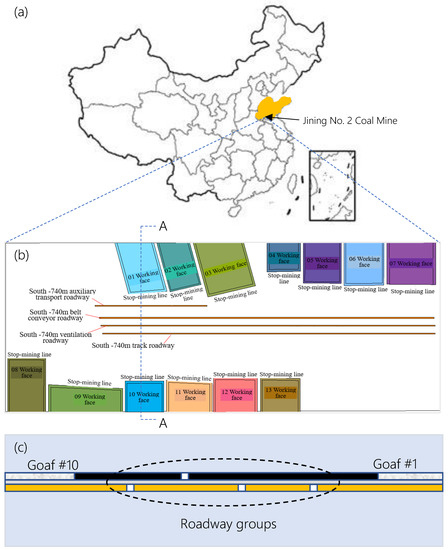
Figure 1.
Locations. (a) Jining No. 2 Coal Mine (b) roadway and working face. (c) Cross-section of A-A.
2.1. Roadway Groups
Figure 1b shows four main alleys at the level of −740 m on the south wing of Jining No. 2 Coal Mine, and the distribution of working faces on both sides. The cross-sectional view is depicted in Figure 1c. The elevations of the track roadway, the ventilation roadway, the belt conveyor roadway, and the auxiliary transportation roadway are −740 m, −732 m, −738 m, and −738 m, respectively. The track roadway and the belt conveyor are 30 m away from the ventilation roadway. The horizontal distance between the belt conveyor roadway and the auxiliary transportation roadway is 50 m. It can be seen that the four main roadways belong to deep wells with large cross-sections, which can be affected by disturbances such as roadway excavation and mining activities.
2.2. Multi-Disturbance of Roadway Groups
The vertical stress of the −740 m roadway reaches 19.45 MPa (the ground elevation is 38 m), which belongs to the high-stress roadway. The thickness of the coal seam in the mining area is between 5 m to 6 m. The range of the stress area is large where the work advances towards the roadway group. The average horizontal spacing of four main lanes at −740 m level is 30 m, and the nearest stop-mining line to the roadway is approximately 40 m [21]. Therefore, the main roadway is projected to various strong mining influences, which makes controlling the surrounding rock of the roadway difficult.
There are four main roadways with large deformations and roadway spans with an average value of more than 4.5 m. The length of the supporting bolt adopted is 2.4 m, and the effective length is 2.3 m. Theoretically, the supporting bolt cannot act as an effective supporting structure. The roof spray strata were cracked severely, and a serious floor heave was observed. A roof fall phenomenon with a falling height of 3 m, and a length of 6.7 m was observed. The partial destruction of the roadway is shown in Figure 2.
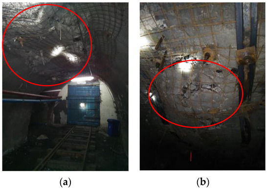
Figure 2.
Damage of roadway. (a) The anchor support failure. (b) Sagging roof.
For monitoring purposes, several drill boreholes were drilled in the belt conveyor roadway, the track roadway, the ventilation roadway, and the auxiliary transportation roadway. The roadway groups facing the 01 and 10 working faces were used as test sections. Three boreholes were set up in each main roadways, having an interval of 50 m. The drilling positions were located in the middle of the roof of the roadway and on both shoulders. The hole diameter is 32 mm and the depth is 10 m. The monitoring drill view of the track roadway is shown in Figure 3. The mudstone is broken severely in deep parts of the borehole and is broken moderately in the coal seam. The surrounding rock remains intact in the middle sandstone part.
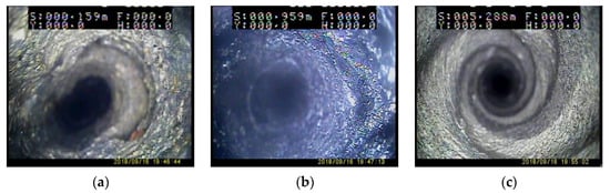
Figure 3.
Peeking observations of the roadway boreholes. (a) Mudstone—badly fractured. (b) Coal seams—medium break. (c) Medium sandstone—surrounding rock intact.
3. Theoretical Analysis
The deformation of the roadway is affected by the mining and the movement of the overlying rock, obtained from on-site measurements. Previous studies only analyzed the influence of main key strata, and thus the impact of rock subsidence on the roadway should be further investigated [32,33]. We combine the key strata and mining subsidence to analyze the overlying rock strata and understand the influence of mining subsidence on the roadway group.
3.1. Discriminating Position of the Key Strata
After the initial collapse of the direct roof, the continuous advancement of the working face can lead to the break of the overburden key strata. To analyze the breaking and caving of the overburden key strata, the position of key strata in the overburden need to be distinguished [34]. After excavation of the roadway group, holes were drilled in the middle of the length of the track roadway. The sampling data were analyzed to reveal the lithology of the overlying rock strata. Figure 4 shows that there are 44 overlying strata. The process employed to determine key strata types of the overlying strata is summarized in Figure 5.
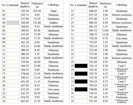
Figure 4.
Histogram analysis of the overburdened rock strata in terms of columnar, buried depth, thickness, and lithology.
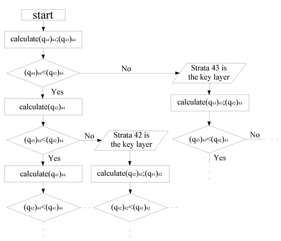
Figure 5.
Key strata calculation flow.
The key strata can control the movement and failure of rock strata in a certain range, and its failure deformation is synchronized with the deformation of overlying rock strata. The calculation process is carried out as shown in Figure 5.
According to the definition of key strata, if layer 1 is the key strata and its control range reach layer n, the discrimination formula for layer n + 1 to become the next key strata is qn+1 < qn. Then, based on the above process (Figure 5), it can be calculated that, , , , , , . Herein, q is the overburden load. The basic roof of the coal seam is 4.95 m siltstone, and thus rock strata of less than 5 m is not considered as the key strata. The buried depth is within the range of −751.95 to −195.50 m. Therefore, the key strata histogram of the rock formation is in the range of −751.95 to −195.50 m. The rock column diagram and key strata types areobtained from the geological histogram, as shown in Table 1.

Table 1.
Rock column diagram and the key strata types.
3.2. Surface Subsidence Theory
Mining subsidence theory refers to the size and spatial distribution of surface movement and deformation caused by underground mining and its relationship with geological mining conditions [35,36,37]. The damage types of surface movement and deformation can be summarized as surface movement basins, cracks, steps, and collapse pits. The previous studies mainly focused on the bending and subsidence of overlying strata caused by mining of the working face, forming the collapse zone, the fracture zone, and the bending subsidence zone.
The surface sinks from its original elevation after being affected the mining. Therefore, a subsidence area much larger than the goaf is formed above the goaf. This kind of surface subsidence area is called a surface movement basin [38,39]. As shown in Figure 6, H (m) is the buried depth of the coal seam, and β (°) is the mining subsidence angle. I is the caving zone, II is the crack zone, and III is the curve subsidence zone. a is a non-affected zone, b is a slightly affected zone, and c is a severely affected zone. If the roadway is located in a severely affected zone during coal seam mining, severe damage would occur. If the roadway is located in an unaffected zone, the roadway would not be affected by mining.
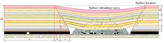
Figure 6.
The profile of surface subsidence curve and mining subsidence angle.
3.3. Advanced Influence of Key Strata Collapse
Using the empirical analogy method, the surface moving basin is gradually formed during the propelling of the working face. When the working face is propelled forward (1/4 to 1/2)H range from the open-off cut, the mining influence can reach the surface causing the surface subsidence [27]. This is evidenced by the existence of large areas of subsidence around mines. Therefore, the following relationship between the advancing distance x of the working face and the height of the roof fracture sinking h(x) can be written:
h = h(x) = 0.25x
According to the previous studies [28,29] and the empirical range, the working face propelling distance x and the crossover influence distance f(x) have the functional relationship as follows:
f = f(x) = 0.125x
The roof fracture of the working face is controlled by the key strata. Starting from the roof corresponding to the coal 3 under No. 45 strata, the height of the key strata, and its corresponding working face propelling distance and influence distance are shown in Table 2. Therefore, the relationship between the propelling distance of the working face and the height of the roof rock strata collapse and the influence height can be obtained, depicted in Figure 7.
Table 2.
Propelling distance and influence values.
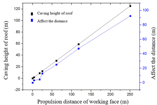
Figure 7.
Relation between working face propel distance and roof caving height and influence distance.
According to Figure 7, as the working face propels, the roof collapse height increases. When the propelling distance of the working face reaches 250 m, the subsidence of the roof affects the ground, causing surface subsidence. The minimum mining advance distance of the working face is 92.35 m. The distance between the stop-mining line of the working face and the roadway is 100 m; the corresponding rock strata above the roadway are not affected by the collapse range.
Jining No. 2 Coal Mine −740 m level four lanes, is an important throat connecting the south wing of the mountain and mining area 9, 13. With the mining on the working faces of both sides of the main roadway, the advanced abutment pressure impacts the stability of four main roadways at the −740 m level, leading to roadway deformations and break of roadway surfaces. The size of the working face and the distance from the adjacent roadway are listed in Table 3.
Table 3.
Statistics of size of the working face and the distance from the adjacent roadway.
According to the calculations, during the mining process of working face in Mining Area 11, the distance between −740 m level auxiliary transportation roadway is relatively small. For example, the distance between 01 working face and auxiliary transportation roadway is 64.18 m, and the distance to the transportation roadway is 81.4 m. Therefore, the mining of the working face impacts the −740 m large roadway. During the mining process, the main roadway is influenced by dynamic and static loads generated by the advanced abutment pressure for a long time period.
The distance from the working face 3 and working face 9 mining areas to the main roadway exceeds 92.35 m, and mining does not affect the main roadway. The distance of the stop-mining line is larger than the influence distance of the mining process of the working face. The impact of mining in the mining area 11 on the −740 m level auxiliary transportation roadway, the belt conveyor roadway, the ventilation roadway, and the track roadway is insignificant with a short time period. Therefore, it is suggested to adopt high strength long bolt and anchor cable combined with grouting to form a support to achieve an effective control effect.
4. Numerical Simulation of Deep Well Roadway Group Disturbance Effect
The cause of instability of surrounding rock in the −740 m horizontal roadway group in the Jining No. 2 Mine is obtained through on-site measurements and theoretical analysis. Furthermore, the instability mechanism of the roadway group is revealed through the combination of theoretical analysis and numerical simulations. The optimal stop-mining line position is determined by simulating the distance from different stop-mining lines to the roadway group, based on the finite difference method [40,41,42]. It is concluded that the surrounding rock support system is affected by the disturbance of the deep roadway group.
4.1. Numerical Simulation Scheme
Taking the −740 m horizontal roadway group in the south wing of Jining No. 2 Mine as the research section, the 100–200 m roadway is taken as the test section within the roadway range of the 01 and 10 working faces. By simulating the mutual influence law of the full excavation of the roadway, and the influence of the two wings working face on the test section roadway during the mining process, we can analyze the damage of the roadway and provide a theoretical basis for later determining the roadway support parameters. We guided the determination of the stop-mining line at the working face. The model has a length of 529.4 m, a height of 140 m, and a width of 30 m. The model contains a total of nine rock strata. A load of 17.5 MPa is applied at the top of the domain to simulate the overburden pressure. The horizontal stresses are set as 21 MPa. The left and right horizontal displacement of the model is limited to within ±0.1 m, and the bottom vertical displacement is limited to within ±0.1 m. The simplified boundary model is shown in Figure 8. The track roadway is arched with a width of 5.0 m and a height of 4.0 m. The belt conveyor roadway is arched, with a width of 5.0 m and a height of 4.8 m. The ventilation roadway is rectangular, with a width of 4.6 m and a height of 3.3 m. The auxiliary transportation roadway is rectangular, with a width of 4.8 m and a height of 3.2 m. Since the inclination angle of the coal seam is only between 2° and 10°, with an average of 5°, it is a nearly horizontal coal seam. The test section roadway is 100 to 200 m. The rock mass properties are shown in Table 4. The properties of the support materials are simulated by cable elements and the parameters are given in Table 5.
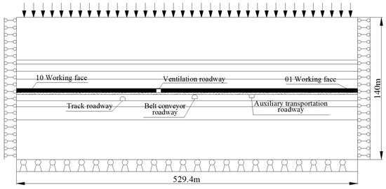
Figure 8.
Simplified model diagram of boundary conditions.
Table 4.
Rock mass properties.
Table 5.
The support materials used in the numerical simulation.
4.2. Influence of Roadway Excavation Disturbance
In the process of excavating a group of roadways (distance 30 to 50 m), the stress redistributes after the roadway is excavated, and there is a mutual influence between the roadways. The stress distribution, displacement distribution, and plastic zone distribution of the surrounding rock of the roadway after excavating the roadway can reveal whether there is a mutual disturbance in the roadway group. The mutual disturbance between the roadways complicates controlling of the surrounding rock of the roadways.
Figure 9 shows the vertical stress distribution of surrounding rock after excavating the roadway group. There are four main roadways at the level of −740 m in the south wing. The distance between the track roadway, the ventilation roadway, and the belt conveyor roadway is 30 m, and there is a slight mutual disturbance between the roadways. The distance between the belt conveyor roadway and the auxiliary transportation roadway is 50 m, and there is no mutual disturbance.
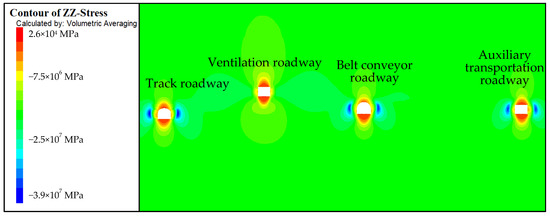
Figure 9.
Vertical stress distribution of surrounding rock behind excavation of roadway group.
Figure 10 shows the surrounding rock displacement cloud diagram after driving the roadway group. After the roadway group is mined, the maximum deformation of the surrounding rock of the roadway is about 9.8 mm under the design support parameters. The deformation of the surrounding rock of the roadway can be controlled for values below 9.8 mm. However, in the later stage of the roadway under the influence of deep high ground stress, the creep deformation increases the deformation of the roadway surrounding rock, and thus it is not considered here.
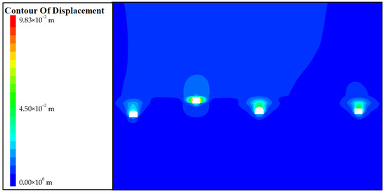
Figure 10.
Displacement of surrounding rock behind the excavation roadway group.
Figure 11 shows the plastic zone distribution of the roadway surrounding rock after excavating the roadway group. The surrounding rock of the roadway has plastic deformations under the condition of stress concentration. For the deep roadway group, the surrounding rock of the roadway has a different distribution of plastic zone under different rock strata conditions. The ventilation roadway is used as a coal seam roadway, and the roof and floor of the roadway have a larger plastic zone. In particular, the floor is mudstone, the depth of the floor plastic zone is about 3.0 m, and the plastic failure range is large, which is difficult for roadway control. In the subsequent roadway treatment process, it is necessary to ensure the quality of the roadway floor support and stability of the floor surrounding rock. For the study of the four roadways, the plastic zone at the top and bottom of the roadway is about 2.5 to 2.6 m, and long bolts are needed to control the surrounding rock of the roadway. The design of a 3 m long anchor rod can realize an anchoring section in the stable rock formation, a long anchor rod, and anchor cable cross-border support, and construct deep and shallow load-bearing rings.
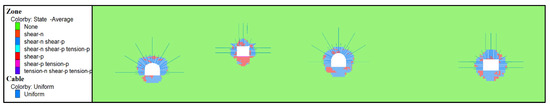
Figure 11.
Distribution of plastic zone after roadway group excavation.
From the stress distribution, deformation, and plastic zone distribution characteristics of the surrounding rock in roadway group excavation, it is determined that the full plastic failure range of the roadway is large, and thus a 2.4 m bolt support is adopted. The anchoring section is within the range of broken surrounding rock, and there is no stable fulcrum to build a deep and shallow load-bearing ring. The surrounding rock of the roadway was repeatedly damaged and repaired. The use of 3.0 m bolts can realize the construction of deep and shallow load-bearing rings, which is a scheme for roadway stability control. Since the simulated model domain is relatively small, the goaf fails to bend and sink after the working face; however, the influence of this effect on the simulation results is insignificant.
4.3. Influence of Mining Disturbance at Working Faces
During the advancing process of the working face in the test section, it is affected by the disturbance of working faces 01 and 10, which belong to the multi-disturbed roadway. The study of the law of influence on the surrounding rock of the roadway, during the mining process of the working face, is of great significance for determining the location of the stop line. The distribution law of stress field, displacement field, and plastic zone were simulated as the working face distances from the roadway of 50 m, 75 m, and 100 m.
The vertical stress distribution of the surrounding rock of the model is shown in Figure 12.
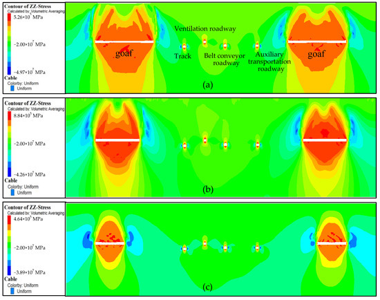
Figure 12.
Vertical stress distribution of the different distances between working face and roadway: (a) 50 m, (b) 75 m, and (c) 100 m.
As shown in Figure 12, mining has disturbance effects on the four main roadways. The disturbance effect of the track roadway and auxiliary transportation roadway is the most severe when the distance between the working face and the roadway is 50 m. The influence of mining on the disturbance of the track roadway and the auxiliary transportation roadway is reduced when the distance between the working face and the roadway increases. Thus, the impact of mining on the roadway group is minimal when the distance between the working face and the roadway is 100 m.
The changes of maximum vertical stress is shown in Figure 13 for distances of 50 m, 75 m, and 100 m between the working face and the roadway. When the roadway group is excavated, the maximum vertical stress on both sides of the track roadway is 39.1 MPa. The maximum vertical stresses on the two sides of the auxiliary transportation roadway are 36.2 MPa and 36.7 MPa, respectively. The maximum vertical stress on both sides of the roadway is increased after mining the coal seam.
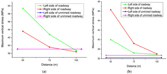
Figure 13.
Maximum vertical stress at different distances between working face and roadway: (a) the track roadway and (b) the auxiliary transportation roadway.
When the distance between the working face and the roadway is from 50 m to 100 m, the maximum vertical stresses on the two sides of the track roadway and the auxiliary transportation roadway are gradually reduced. When the distance between the working face and the roadway is 100 m, the changing rate of the maximum vertical stress has the lowest value. The horizontal displacement distribution of the surrounding rock of the model roadway is shown in Figure 14.
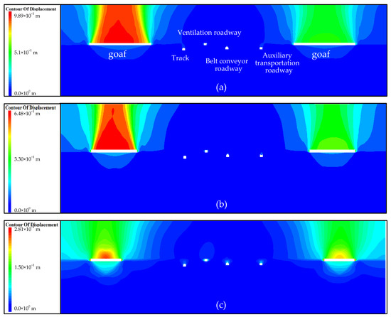
Figure 14.
Vertical displacement diagram of different distances between working face and roadway: (a) 50 m, (b) 75 m, and (c) 100 m.
As shown in Figure 14, when the distance between the working face and the roadway is 50 m, the four main roadways are affected by the disturbance of the mining. The track roadway and auxiliary transportation roadway have the largest deformation. When the distance is 75 m, the disturbance of the ventilation roadway and the belt conveyor roadway is not obvious, and the deformation of the track roadway and auxiliary transportation roadway is relatively large. When the distance between is 100 m, the mining has no obvious disturbing effect on the ventilation roadway and the belt conveyor roadway, and the track roadway and auxiliary transportation roadway are slightly deformed.
The maximum horizontal displacement changes are shown in Figure 15 when the distances between the working face and the roadway are 50 m, 75 m, and 100 m. When the roadway group is excavated, the maximum horizontal displacements of the two sides of the track roadway are 2.2 cm and 2.1 cm, respectively, and the maximum horizontal displacements of the two sides of the auxiliary transportation roadway are 2.6 cm and 2.61 cm, respectively. After the coal seam is mined, the deformation of both sides of the roadway increases. When the distance between the working face and the roadway is between 50 m and 100 m, the maximum displacement of the ventilation roadway and the auxiliary transportation roadway is gradually reduced. When the distance between the working face and the roadway is 100 m, the changing rate of the maximum horizontal displacement has the lowest values. The plastic zone distribution of the surrounding rock of the model roadway is depicted in Figure 16.
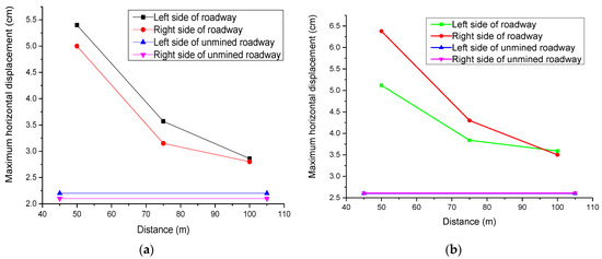
Figure 15.
Maximum vertical displacement at different positions of working face and roadway: (a) the track roadway and (b) the auxiliary transportation roadway.
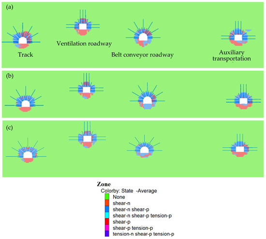
Figure 16.
Distribution of plastic zone at different distances between working face and roadway: (a) 50 m, (b) 75 m, and (c) 100 m.
When the distance between the working face and the roadway is 50 m, the plastic areas of the four main roadways become larger, and the track roadway and the auxiliary transportation roadway change significantly. When the roadway is 75 m, the plastic areas of the ventilation roadway and the belt conveyor roadway change slightly while the track roadway and the auxiliary transportation roadway changes more significantly. When the distance is 100 m, the change of the plastic zone of the ventilation roadway and the belt conveyor roadway is relatively small, and the changes of the track roadway and the auxiliary transportation roadway are insignificant.
In summary, when the distance between the working face and the roadway is 100 m, the mining face has an insignificant influence on the stress distribution, displacement distribution, and plastic zone of the roadway surrounding rock. The key strata theory and the theory of surface subsidence are verified. When the remaining width of the coal pillar exceeds the subsidence range of the rock strata, it would not affect the roadway. Therefore, it can be considered that retaining coal pillars of more than 100 m is beneficial to the stability control of the surrounding rock of the roadway.
5. Conclusions
The mining disturbance was investigated by using the key strata theory. The findings were verified by the results of numerical simulations. The following conclusions can be highlighted:
- (1)
- The overlying rock strata of the working face were analyzed using the theory of key strata and the theory of surface subsidence. The curve relationship between advancing distance of working face and leading influence distance was obtained. The results reveal the influence mechanism of mining disturbances on the rock formation and surface subsidence. The main key strata play a crucial role in the movement of the overlying strata. The subsidence curve and subsidence angle formed by the movement of the rock strata have an important influence on the mining face.
- (2)
- The key strata theory and surface subsidence theory were verified by using numerical simulations. The modeling results reveal the mechanism of advanced influence of the working face. A reasonable coal pillar width is determined. The safety and stability of the roadway group to serve the mining activity are obtained.
Author Contributions
Conceptualization by Y.S. and G.L.; methodology, J.H.; investigation, J.Z.; writing—original draft preparation, Y.S.; writing—review and editing, G.L., J.S., J.Z., Q.C. and R.B.; supervision, G.L. and R.T.; funding acquisition, G.L. and Q.C. All authors have read and agreed to the published version of the manuscript.
Funding
This research was supported by the projects of “the Fundamental Research Funds for the Central Universities (2020ZDPY0221, 2021QN1003)”, “National Natural Science Foundation of China (52104106, 52174089)”.
Institutional Review Board Statement
Not applicable.
Informed Consent Statement
Not applicable.
Data Availability Statement
The data presented in this study are available on request from the corresponding author. The data are not publicly available due to privacy.
Acknowledgments
The authors are grateful to Shandong Energy Group Co. Ltd. Special thanks to Zuqi Wang for her encouragements.
Conflicts of Interest
The authors declare no conflict of interest.
References
- Basarir, H.; Sun, Y.; Li, G. Gateway stability analysis by global-local modeling approach. Int. J. Rock Mech. Min. Sci. 2019, 113, 31–40. [Google Scholar] [CrossRef]
- Li, G.-C.; Ma, Z.-Q.; Zhang, N.; Wang, P.-P.; Ma, R. Research on failure characteristics and control measures of roadways affected by multiple overhead mining in Huaibei mining area. J. Min. Saf. Eng. 2013, 30, 181–187. [Google Scholar]
- Li, G.-C.; Zhang, N.; Cao, P.; Zhang, N.-C.; Wei, Y.-H. An extension model for safety assessment of roadways with a weak interlayer roof. J. China Univ. Min. Technol. 2013, 42, 24–30. [Google Scholar]
- Li, G.-C.; Sun, H.; Zhang, N.; Jiang, Z.-H.; Zhang, Z.-L. Application research on new high-strength anchor cable bundle based on the shear stress distribution of anchor cable. J. China Coal Soc. 2015, 40, 1008–1014. [Google Scholar]
- Sun, Y.; Li, G.; Zhang, J.; Qian, D. Stability Control for the Rheological Roadway by a Novel High-Efficiency Jet Grouting Technique in Deep Underground Coal Mines. Sustainability 2019, 11, 6494. [Google Scholar] [CrossRef] [Green Version]
- Sun, Y.; Li, G.; Zhang, J.; Qian, D. Experimental and numerical investigation on a novel support system for controlling roadway deformation in underground coal mines. Energy Sci. Eng. 2020, 8, 490–500. [Google Scholar] [CrossRef] [Green Version]
- Sun, J.; Aslani, F.; Wei, J.; Wang, X. Electromagnetic absorption of copper fiber oriented composite using 3D printing. Constr. Build. Mater. 2021, 300, 124026. [Google Scholar] [CrossRef]
- Zhang, J.; Yao, Z.; Wang, K.; Wang, F.; Jiang, H.; Liang, M.; Wei, J.; Airey, G. Sustainable utilization of bauxite residue (Red Mud) as a road material in pavements: A critical review. Constr. Build. Mater. 2020, 270, 121419. [Google Scholar] [CrossRef]
- Sun, J.; Aslani, F.; Lu, J.; Wang, L.; Huang, Y.; Ma, G. Fresh and mechanical behaviour of developed fibre-reinforced lightweight engineered cementitious composites for 3D concrete printing containing hollow glass microspheres. Ceram. Int. 2021. [Google Scholar] [CrossRef]
- Kan, J.-G.; Zhang, N.; Li, G.-C.; Wang, C.; Zhang, D.-H. Analysis of excavation method of large span open-off cut in deep mine. J. Min. Saf. Eng. 2009, 26, 163–167. [Google Scholar]
- Li, G.; Sun, Y.; Zhang, J.; Zhang, Q.; Sun, C.; Zhang, S.; Bi, R. Experiment and Application of Coalcrete on Roadway Stability: A Comparative Analysis. Adv. Mater. Sci. Eng. 2020, 2020, 1–14. [Google Scholar] [CrossRef]
- Wang, C.; Zhang, N.; Han, C.-L.; Li, G.-C.; Qian, D.-Y. Numerical analysis and application of the relationship between surrounding rock and U-shaped shed under leg locking. J. Min. Saf. Eng. 2011, 28, 209–213. [Google Scholar]
- Sun, Y.; Li, G.; Zhang, J.; Sun, J.; Xu, J. Development of an Ensemble Intelligent Model for Assessing the Strength of Cemented Paste Backfill. Adv. Civ. Eng. 2020, 2020, 1–6. [Google Scholar] [CrossRef]
- Sun, Y.; Li, G.; Zhang, N.; Chang, Q.; Xu, J.; Zhang, J. Development of ensemble learning models to evaluate the strength of coal-grout materials. Int. J. Min. Sci. Technol. 2021, 31, 153–162. [Google Scholar] [CrossRef]
- Zolfaghari, A.; Bidar, A.S.; Javan, M.M.; Haftani, M.; Mehinrad, A. Evaluation of rock mass improvement due to cement grouting by Q-system at Bakhtiary dam site. Int. J. Rock Mech. Min. Sci. 2015, 74, 38–44. [Google Scholar] [CrossRef]
- Zhang, Z.; Shimada, H.; Sasaoka, T.; Hamanaka, A. Stability Control of Retained Goaf-Side Gateroad under Different Roof Conditions in Deep Underground Y Type Longwall Mining. Sustainability 2017, 9, 1671. [Google Scholar] [CrossRef] [Green Version]
- Wu, K.; Shao, Z.; Qin, S. An analytical design method for ductile support structures in squeezing tunnels. Arch. Civ. Mech. Eng. 2020, 20, 1–13. [Google Scholar] [CrossRef]
- Wu, K.; Shao, Z.; Qin, S.; Wei, W.; Chu, Z. A critical review on the performance of yielding supports in squeezing tunnels. Tunn. Undergr. Space Technol. 2021, 115, 103815. [Google Scholar] [CrossRef]
- Li, S.C.; Wang, Q.; Wang, H.T.; Jiang, B.; Wang, D.C.; Zhang, B.; Li, Y.; Ruan, G.Q. Model test study on surrounding rock deformation and failure mechanisms of deep roadways with thick top coal. Tunn. Undergr. Space Technol. 2015, 47, 52–63. [Google Scholar] [CrossRef]
- Utsuki, S.; Mito, Y. Development of Grouting Management Support System And its Application to Actual Dam Grouting. In Proceedings of the 47th US Rock Mechanics/Geomechanics Symposium, San Francisco, CA, USA, 23–26 June 2013. [Google Scholar]
- Huang, J.; Zhang, Y.; Sun, Y.; Ren, J.; Zhao, Z.; Zhang, J. Evaluation of pore size distribution and permeability reduction behavior in pervious concrete. Constr. Build. Mater. 2021, 290, 123228. [Google Scholar] [CrossRef]
- Sharifzadeh, M.; Tarifard, A.; Moridi, M.A. Time-dependent behavior of tunnel lining in weak rock mass based on displacement back analysis method. Tunn. Undergr. Space Technol. 2013, 38, 348–356. [Google Scholar] [CrossRef]
- Meng, B.; Jing, H.; Chen, K.; Su, H. Failure mechanism and stability control of a large section of very soft roadway surrounding rock shear slip. Int. J. Min. Sci. Technol. 2013, 23, 127–134. [Google Scholar] [CrossRef]
- Wang, D.; Zhang, Q.; Chen, Q.; Qi, C.; Feng, Y.; Xiao, C. Temperature variation characteristics in flocculation settlement of tailings and its mechanism. Int. J. Miner. Met. Mater. 2020, 27, 1438–1448. [Google Scholar] [CrossRef]
- Gong, P.; Jin, Z. Mechanical model study on roof control for fully-mechanized coal face with large mining height. Chin. J. Rock Mech. Eng. 2008, 27, 193–198. [Google Scholar]
- Lu, C.-P.; Dou, L.-M.; Liu, B.; Xie, Y.-S.; Liu, H.-S. Microseismic low-frequency precursor effect of bursting failure of coal and rock. J. Appl. Geophys. 2012, 79, 55–63. [Google Scholar] [CrossRef]
- Sun, J.; Lin, S.; Zhang, G.; Sun, Y.; Zhang, J.; Chen, C.; Morsy, A.M.; Wang, X. The effect of graphite and slag on electrical and mechanical properties of electrically conductive cementitious composites. Constr. Build. Mater. 2021, 281, 122606. [Google Scholar] [CrossRef]
- Sun, J.; Huang, Y.; Aslani, F.; Ma, G. Properties of a double-layer EMW-absorbing structure containing a graded nano-sized absorbent combing extruded and sprayed 3D printing. Constr. Build. Mater. 2020, 261, 120031. [Google Scholar] [CrossRef]
- Sun, Y.; Li, G.; Basarir, H.; Karrech, A.; Azadi, M.R. Laboratory evaluation of shear strength properties for cement-based grouted coal mass. Arab. J. Geosci. 2019, 12, 1–11. [Google Scholar] [CrossRef]
- Sun, C.; Li, G.; Gomah, M.E.; Xu, J.; Sun, Y. Creep characteristics of coal and rock investigated by nanoindentation. Int. J. Min. Sci. Technol. 2020, 30, 769–776. [Google Scholar] [CrossRef]
- Sun, Y.; Li, G.; Zhang, J. Investigation on jet grouting support strategy for controlling time-dependent deformation in the roadway. Energy Sci. Eng. 2020, 8, 2151–2158. [Google Scholar] [CrossRef] [Green Version]
- Zhang, Z.; Xu, J.; Zhu, W.; Shan, Z. Simulation research on the influence of eroded primary key strata on dynamic strata pressure of shallow coal seams in gully terrain. Int. J. Min. Sci. Technol. 2012, 22, 51–55. [Google Scholar] [CrossRef]
- Wang, S.; Li, X.; Wang, S. Separation and fracturing in overlying strata disturbed by longwall mining in a mineral deposit seam. Eng. Geol. 2017, 226, 257–266. [Google Scholar] [CrossRef]
- Xu, T.; Yang, T.-H.; Chen, C.-F.; Liu, H.-L.; Yu, Q.-L. Mining induced strata movement and roof behavior in underground coal mine. Géoméch. Geophys. Geo-Energy Geo-Resour. 2015, 1, 79–89. [Google Scholar] [CrossRef] [Green Version]
- Miao, X.; Pu, H.; Bai, H. Principle of water-resisting key strata and its application in water-preserved mining. J. China Univ. Min. Technol. Ed. 2008, 37, 1. [Google Scholar]
- Ju, J.; Xu, J. Structural characteristics of key strata and strata behaviour of a fully mechanized longwall face with 7.0 m height chocks. Int. J. Rock Mech. Min. Sci. 2013, 58, 46–54. [Google Scholar] [CrossRef]
- Miao, X.; Qian, M. Advance in the key strata theory of mining rockmass. J. China Univ. Min. Technol. 2000, 29, 25–29. [Google Scholar]
- Yang, Z.; Liu, C.; Zhu, H.; Xie, F.; Dou, L.; Chen, J. Mechanism of rock burst caused by fracture of key strata during irregular working face mining and its prevention methods. Int. J. Min. Sci. Technol. 2018, 29, 889–897. [Google Scholar] [CrossRef]
- Dawei, Z.; Kan, W.; Zhihui, B.; Zhenqi, H.; Liang, L.; Yuankun, X.; Xinpeng, D. Formation and development mechanism of ground crack caused by coal mining: Effects of overlying key strata. Bull. Eng. Geol. Environ. 2017, 78, 1025–1044. [Google Scholar] [CrossRef]
- Sun, Y.; Zhang, J.; Li, G.; Ma, G.; Huang, Y.; Sun, J.; Wang, Y.; Nener, B. Determination of Young’s modulus of jet grouted coalcretes using an intelligent model. Eng. Geol. 2019, 252, 43–53. [Google Scholar] [CrossRef]
- Sun, Y.; Li, G.; Zhang, J. Developing Hybrid Machine Learning Models for Estimating the Unconfined Compressive Strength of Jet Grouting Composite: A Comparative Study. Appl. Sci. 2020, 10, 1612. [Google Scholar] [CrossRef]
- Sun, Y.; Li, G.; Zhang, J.; Xu, J. Failure Mechanisms of Rheological Coal Roadway. Sustainability 2020, 12, 2885. [Google Scholar] [CrossRef] [Green Version]
Publisher’s Note: MDPI stays neutral with regard to jurisdictional claims in published maps and institutional affiliations. |
© 2021 by the authors. Licensee MDPI, Basel, Switzerland. This article is an open access article distributed under the terms and conditions of the Creative Commons Attribution (CC BY) license (https://creativecommons.org/licenses/by/4.0/).