Featured Application
This work proposes a newly designed single-piston miniature free-piston generator, which features simple configuration and better sealing. This device has promising applications as the power source for small-scale electrical equipment and portable devices. This work carried out the preliminary parametric study of its performance and the findings provide a theoretical standpoint for the research on piston trajectory control.
Abstract
The miniaturization of electrical equipment and popularization of portable devices is an appealing motivation for the development of small-scale heat engines. However, the in-cylinder charge leaks severely as the engine dimension shrinks. The free-piston engine on a small scale provides better sealing than other miniature heat engines. Therefore, a miniature free-piston generator (MFPG) with a single-piston internal combustion engine (ICE) and a voice coil motor (VCM) was proposed in this work. A dynamic model with special attention on the heat transfer and leakage was established accordingly, upon which parametric studies of leakage and its effects on the performance of the MFPG system were performed. Four key parameters, including scavenging pressure, ignition position, combustion duration and piston mass, were considered in the model. The results showed that the mass leakage during the compression decreases with the rise of the motoring current. The indicated thermal efficiency can be improved by boosting scavenging pressure and increase motoring current. The critical ignition position is 2 mm before the top dead center. When ignition occurs later than that, the MFPG system is incapable of outputting power. The chemical to electric energy conversion efficiency is about 5.13%, with an output power of 10~13 W and power density around 4.7~5.7 W/cc.
1. Introduction
The design and manufacture of micro/small scale heat engines have drawn wide attention in all the works due to the relatively low energy density of chemical batteries [,,]. The energy density of hydrocarbon fuels is 75 times higher than that of an ordinary lithium battery [,]. A heat engine with an energy conversion efficiency of no less than 2.5% can achieve a higher energy density than all the existing chemical batteries []. The experimental investigation of a 20 mm ultra-micro scale gas turbine obtained 15 W at 60,000 rpm. Thermal cyclic efficiency of 18.6% was attained []. A micro linear power generation system was proven to reach an energy density of 180 Whr/kg [], which is on the upper limit of rechargeable lithium batteries []. A variety of small-scale heat engine prototypes have been developed and investigated in the form of micro gas turbines [,,,,], micro rotor engines [,,], micro internal combustion swing engines [,,], micro free-piston generators [,,,], micro steam turbine [,,] and micro P3 (Personal Power Pack) external combustion engines [,].
Free-piston heat engines do not involve the conventional rod–crankshaft mechanism, so its piston motion is determined by the resultant force of external forces acting on the piston. Compared to other micro heat engines, the free-piston configuration has advantages of a simple structure, better sealing and controllable compression ratio [,]. Although the operation frequency is relatively low, it also degrades the requirements on materials and bearings. In addition, the wider fuel adaptability and flexible piston trajectory provide a new way to improve the thermal efficiency of the system [,]. Aichlmayr et al. [,] carried out a fundamental study of the combustion process of a free-piston combustor as small as 3 mm in diameter and 0.3 mm in length. They stated that to generate 10–20 W power in 103 mm3, the time scale of compression and expansion stroke must be much smaller than that of thermal diffusion, indicating a completely adiabatic combustion process. Therefore, a small-scale free-piston engine with ultra-high frequency could achieve higher theoretical thermal efficiency. However, with the reduction in the scale, the heat loss caused by the resulting enormous area-to-volume ratio and the leakage caused by the sealing problem between the piston and cylinder both increase severely, which limits the improvement of engine efficiency.
Lungu et al. [] proposed a small-scale high-aspect-ratio free-piston engine. They applied two different sealing methods. Their experiment demonstrated that the better sealing resulted in a longer stroke, 6.35 mm, compared to a 3.175 mm stroke obtained by the worse sealing method. A significant improvement in power generation is obtained with the better sealing method. Suzuki et al. [] manufactured a 0.0095 cc miniature free-piston generator on a silicon wafer. Single ignition combustion was successfully realized with an output power of 29.1 mW. However, the in-cylinder peak pressure was only 142.6 kPa, whereas the theoretical value was 349 kPa, indicating a serious leakage and heat loss. Lee et al. [] also proposed an ultra-miniature free-piston generator using the sandwich structure to reduce heat loss. The single ignition stroke was 2.7 mm compared to a designed piston stroke of 8 mm, due to the serious leakage and heat loss. In addition, Tian et al. [] contributed the low conversion efficiency of around 0.6% of their free-piston compressor to the combined effect of severe leakage, heat transfer and friction. Huang et al. [] tested the performance of a reciprocating free-piston linear engine with a pair of 22.4 mm diameter combustion chambers. The engine output was 31.6 W power and it attained 42.8% thermal efficiency with an external resistance of 6.3 Ω. However, the researchers did not mention the sealing method in their paper.
Some theoretical analyses on the leakage and heat transfer of miniature heat engines have been carried out [,,,,,]. Sher et al. [] pointed that the leakage gap is essentially the same regardless of the engine size. It is mainly determined by the fabrication tolerance, which is around 10~20 μm. The gas leakage per cycle is two orders of magnitude higher than that of conventional internal combustion engines (ICEs) because there are no piston rings between the piston and the cylinder wall in micro ICEs. Tian et al. [] fitted Sher’s analytic simulation with a leakage discharge coefficient of 0.12, then argued that their work exaggerated the leakage by not considering the sealing effect of lubricant oil. Instead, they proposed a smaller value of 0.06 and reasonably reproduced their own experimental cylinder pressure. Annen et al. [] stated that leakage loss becomes very important when the size of the micro-heat engine is smaller than 20 W. Various solutions are proposed for different prototypes, including the usage of sealing parts and lubricant [], adopting more advanced bonding technology for the sandwich structure [], applying liquid piston structure [] and improving the fabrication technology to reduce the gap width [].
Heat loss is another major factor leading to inefficiency or flame extinction of micro-engines [,,]. As the engine dimension shrinks, the area-to-volume ratio increases, resulting in greater heat transfer loss per unit volume. Drost et al. [] carried out many tests on the extinguishing distance of propane/oxygen mixture in order to determine the suitable combustion chamber size. Annen et al. [] simulated the heat loss of a miniature reciprocal ICE, and determined the cylinder wall temperature required to limit the heat loss under 20% and 30% of the total heat released by fuel combustion at different scales.
Attracted by the advantages of the free-piston scheme, a single-piston miniature free-piston generator (MFPG) prototype, which directly converts hydrocarbon fuel into electricity, is proposed in this work. The prototype is constructed by combining a miniature internal combustion engine (ICE) with a compatible voice coil motor (VCM). To better understand the influence of leakage and heat transfer on the efficiency of this MFPG, a dynamic model, including heat transfer and leakage sub-models, was established and the parametric study of leakage and its effects on the performance of the MFPG were performed. The energy conversion in the MFPG prototype is also investigated by analyzing the transient power flow among each component force. This study provides a theoretical analysis for the subsequent system optimization.
2. MFPG Prototype
The schematic configuration and test bench of the proposed MFPG system are shown in Figure 1a,b.
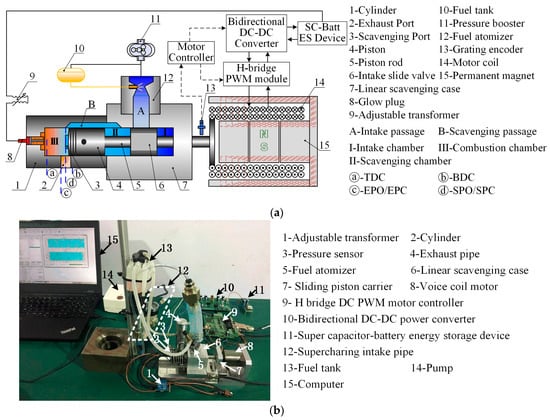
Figure 1.
The miniature free-piston generator (MFPG) prototype. (a) The MFPG schematic diagram; (b) The MFPG test bench.
As is seen from the picture, the proposed MFPG consists of a reciprocating internal combustion engine (ICE), a voice coil motor (VCM), a control unit and a super capacitor-battery energy storage device pack (SC-Batt ES). The conventional rod–crankshaft unit is diminished, and the ICE and the VCM are coupled directly through an integrated piston-valve rod. Thus, the piston-valve rod moves without the constraint of the crankshaft and its movement is governed by the external force acting on the rod. It has been proven that the quenching effect increases with the decrease in cylinder diameter [] and the piston frequency soars with the reduction in piston mass, which is adverse to trajectory control []. Therefore, in order to obtain better combustion and easier trajectory control for future work, a 2.5 cc small scale ICE cylinder is selected. It is a smaller version of a conventional two-stroke ICE. Kim et al. [] built a prototype on the same cylinder structure with a larger diameter and explained the structure in detail.
For a conventional engine, thanks to the rod–crankshaft unit and the flywheel, the energy and torque generated during the compression stage are stored and released in the other stages. Thus, the energy is transferred continuously and smoothly during a complete working cycle. In contrast, the energy flow in a free-piston engine is balanced during a single stroke, so continuous motion is a big challenge for free-piston structures. Usually, an extra piston rebounding unit is a necessary part of a free-piston heat engine. However, the proposed MFPG prototype is designed as simply as possible to accommodate size reduction and reduce the risk of failure []. The major simplifications include: (1) the common used spark plug is replaced by a platinum glow plug; (2) A miniature atomizer is used for the fuel atomization instead of the electronic fuel injection system; (3) A self-designed linear valve-port scavenging case without extra electrical and moving parts is applied; (4) The VCM serves as both the energy storage and piston rebounding component, compared to other configurations usually contain separate parts for the piston rebounding.
The MFPG is essentially an internal combustion engine and needs to follow the basic thermodynamic cycle to output work. Thus, a complete working cycle of the MFPG also consists of four main stages, which are scavenging, compression, expansion and exhaust. Figure 2 shows a complete working cycle of the MFPG system. The scavenging stroke starts when the scavenging port opens (SPO), the piston is driven by the in-cylinder pressure to the BDC and motored back by the VCM to the scavenging port closing (SPC). When the piston moves negatively to the position of exhaust port closing (EPC), the combustion chamber III is sealed and the system enters the compression stroke. When the piston stops at the top dead center, with the assistant of the glow plug, the combustible mixture ignites and the in-cylinder pressure rises rapidly to push the piston back. The MFPG enters the expansion stroke, in which the VCM is working on the generator mode. The exhaust stroke starts when the piston reaches EPO and ends after the piston stops at BDC. These entire four strokes constitute a complete working cycle, then the piston is ready to start the next cycle. The piston continuously moves back and forth to transform the fuel energy into electricity.
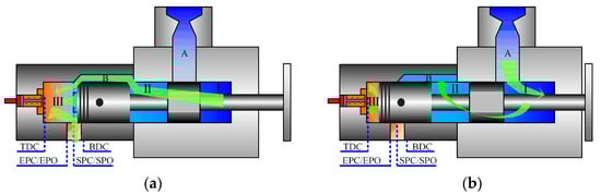
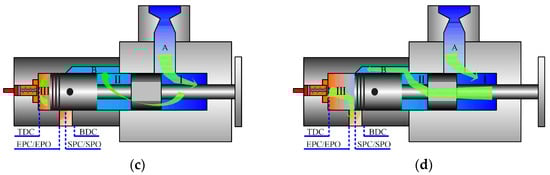
Figure 2.
Working principle of the MFPG prototype. (a) Scavenging stroke; (b) Compression stroke; (c) Expansion stroke; (d) Exhaust stroke. The green arrows display the air flow during the four strokes.
The MFPG specifications are listed in Table 1 and the configuration of the piston coordinates is shown in Figure 3. The MFPG has a shorter residence time at the TDC than conventional ICEs, so the fuel adopted in the MFPG prototype has to be faster in flame speed [,]. Methanol (CH3OH) has a flame propagation speed of 0.523 m/s, which is much higher than 0.337 m/s and 0.39 m/s of gasoline and diesel [], respectively. As an oxygenated fuel, its ignition limit is 6.7~36%, which is wider than that of traditional fuels, in addition to the lower minimum ignition energy, which is conducive to the rapid formation of a flame core. Moreover, methanol can burn stably when the exhaust gas recirculation (EGR) is more than 23% []. This feature can tolerate the low scavenging efficiency of a two-stroke engine and is therefore beneficial in complete combustion and reducing cycle variation. Methanol is then selected as the fuel of this MFPG prototype.

Table 1.
Specifications of the miniature free-piston generator (MFPG) prototype.
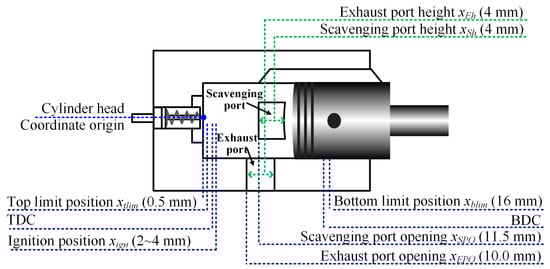
Figure 3.
Configuration of the piston coordinates.
3. Modelling of the MFPG System
The modeling of the MFPG system is a multi-physics problem since it couples a linear motor with an internal combustion engine []. Therefore, a dynamic model of the MFPG prototype is proposed here, consisting of a heat release model, gas exchange model and electromagnetic force model, etc. Special attention is drawn to the modeling of the mass leakage through the cylinder–piston gap and the heat transfer through the cylinder wall.
3.1. Dynamic Model
The piston assembly of the MFPG prototype is governed by the resultant of all the external forces [], thus, the dynamic model of the piston assembly is described as:
where, mp is the piston mass, kg; is the piston acceleration, m·s−2; Ff is the frictional force, N; Fele is the electromagnetic force of the voice coil motor, N; Fgas is the gas force inside the combustion chamber, N.
3.2. Heat Transfer Model
The heat convection across the cylinder wall is the dominant mode of heat dissipation in the MFPG system [,,]. Therefore, in order to simplify the model and accelerate the calculation, the composition inhomogeneity and temperature gradient inside the combustion cylinder can be reasonably neglected [,]. Wu et al. [] and Li et al. [] adopted these assumptions of uniform charge in modelling the heat transfer. Their simulation showed good agreement against test results. Thus, the heat loss of the MFPG system is simply approximated by Newton’s law of cooling []:
where Qw is the heat loss across the cylinder wall, J; Aw is the effective area of heat transfer, m2; T is the in-cylinder gas temperature, K; Tw is the wall temperature, K; aw is the convective heat transfer coefficient, W/(m2·K), which is usually estimated by experiments or simulations.
Two commonly used estimation formulas of aw are the Woschni model [] and the Hohenberg model [], as shown in Equations (3) and (4).
where p, T, V are the pressure, temperature and volume of the in-cylinder gas, with the unit of Pa, K, m3, respectively; pEPC, TEPC and VEPC are the pressure, temperature and volume of the in-cylinder gas at the exhaust port closing, with the unit of Pa, K and m3, respectively; Vh is the swept volume, m3; vmax is the max piston velocity, m/s.
Figure 4a compares the effects of the two heat transfer models on the in-cylinder pressure. Compared to the Woschni model, the Hohenberg model predicts higher in-cylinder gas pressure and shows better agreement against the test data. Since the real in-cylinder gas temperature of the MFPG is unavailable due to the technical obstacles in the field of internal combustion design [,], Figure 4b only displays the simulated in-cylinder gas temperatures of the two models, in conjunction with the adiabatic condition. It shows that the Hohenberg model also predicts higher in-cylinder gas temperature than that of the Woschni model. This explains the cause of the higher in-cylinder gas pressure calculated by the Hohenberg model. The better agreement for the Hohenberg model on the in-cylinder pressure indicates that this model is more suitable for the MFPG prototype studied in this paper.

Figure 4.
Heat transfer model vs. the pressure and temperature of in-cylinder gas. (a) In-cylinder gas pressure vs. piston displacement; (b) In-cylinder gas pressure vs. expanded piston displacement.
3.3. Mass Leakage Model
The leakage process is modeled by a simplified scenario, in which the combustion chamber is regarded as a control volume and the mass flow rate of the in-cylinder gas through the cylinder–piston gap is considered as an orifice flow []:
where mleak is mass of the leaked gas, kg; μcdl is discharge coefficient of the leakage passage; Aleak is leakage area of the piston–cylinder unit, m2; Ψlsub, Ψlsup are subsonic and supersonic flow functions of the in-cylinder gas leakage; pI, and pII are upstream and downstream pressures of the throttling orifice, Pa; ρI and ρII are upstream and downstream densities of the throttling orifice, kg/m3; γ is the adiabatic exponent.
The simulation of the leakage characteristics of the MFPG prototype is shown in Figure 5 along with that of two other micro heat engines, micro conventional crank shaft engines and micro rotary engines. The three types of micro engines are of the same displacement of 2.5 cc. The leakage characteristics of the micro conventional crank shaft engines and micro rotary engines are collected from the literature [,], while that of the MFPG is calculated by the proposed model. The gap widths are set to be 20, 15 and 10 μm, respectively. The discharge coefficient μcdl is assumed to be 0.06 to account for the sealing effect of the lubricant oil in the piston–cylinder gap, as suggested by Tian et al. [].
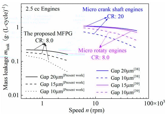
Figure 5.
Comparison of in-cylinder gas leakage of micro internal combustion engines.
The revolution of the other two micro engines is around 6000~14,000 rpm, while the equivalent engine revolution of the MFPG prototype varies from 600 to 2000 rpm. In comparison with these two micro engines, the lower operation frequency of the MFPG would increase the mass leakage to some extent. However, the much lower compression ratio, compared with the micro conventional crank shaft engines, would help reduce the mass leak of the MFPG significantly. Thus, it is reasonable for the calculated leakage of the MFPG, with the suggested μcdl 0.06, to be smaller than that of the micro conventional crank shaft engines. Likewise, with the same displacement and with an identical compression ratio, micro rotary engines leak much more severely than the reciprocating engines []. Thus, with the suggested μcdl 0.06, the calculated leakage of the MFPG is smaller than that of the micro rotary engines, which also makes sense. Therefore, the proposed leakage model along with the selected leakage discharge coefficient μcdl is considered to be a reasonable estimation of mass leakage characteristics of the proposed MFPG prototype.
3.4. Model Validation
The proposed heat transfer model and the leakage model of in-cylinder gas were validated against the experiment data and literature data, as shown in Figure 4 and Figure 5, respectively. The proposed simulation model was validated against the preliminary test under three different scavenging pressures psc, as is illustrated in Figure 6. It is seen that the pressure prediction is generally lower than the tested data. As the psc increases, the piston top dead center (TDC) shifts farther from the cylinder head and the in-cylinder pressure trace becomes sharper indicating a higher degree of isochoric combustion. The predicted in-cylinder pressure seems not able to capture these variations of TDC and combustion process. It is because these parameters are set to be constant in the model, while these variables are strongly coupled with the piston dynamics, which hardly excludes their effects to conduct the test of a single parameter. However, the simulation well predicts the pressure increase trend and agrees with the pressure trace reasonably. The maximum relative errors were 2.9%, 5.6% and 10.5%, respectively, at psc = 1.05, 1.10 and 1.15 bar. The results confirmed that the proposed model is able to reasonably captures the characteristics of the MFPG system, especially if it takes more parameters into consideration.
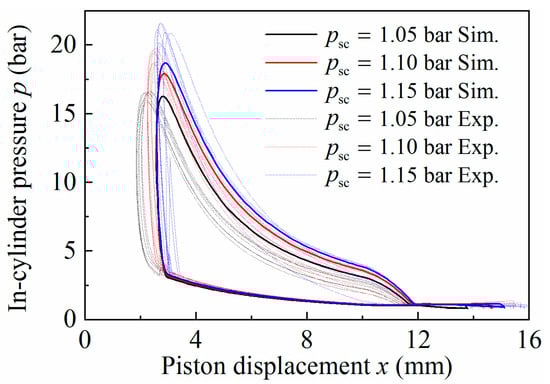
Figure 6.
Model validation against the measured in-cylinder gas pressure.
4. Parametric Study on Leakage and Performance
In this section, the effects of scavenging pressure psc, ignition position xign, combustion duration tcd and piston mass mp are investigated based on the established dynamic model. In addition, the indicated thermal efficiency ηi and effective thermal efficiency ηe are calculated as well to evaluate the performance of the MFPG system.
The mass of the in-cylinder gas at exhaust port closing is denoted as mgepc, which implied the mass sealed in cylinder. The gas mass at combustion start, denoted as mgsoc, is the mass of charge that actually participated in combustion. Thus, the difference between these two is the mass leaked during compression, denoted as:
where, mlcp is the mass leakage of the in-cylinder gas during compression, kg; mgepc is the mass of the in-cylinder gas at EPC, kg; mgsoc is the mass of the in-cylinder gas at SOC, kg.
mlcp = mgepc − mgsoc
Likewise, the mass leaked during combustion and expansion, which affects the work performed by the in-cylinder gas, is denoted as mlexp. It can be calculated by deducting the gas mass at the exhaust port opening (EPO) from that of the start of combustion (SOC).
where, mlexp the mass leakage of the in-cylinder gas during combustion and expansion, kg; mgepo is the mass of the in-cylinder gas at EPO, kg; mgsoc is the gas mass at SOC, kg.
mlexp = mgsoc − mgepo
To investigate the effects of leakage loss and heat loss on system performance, the efficiencies are calculated under three hypotheses:
Hypothesis 1 (H1).
The cylinder was completely sealed and combustion was adiabatic, which is the ideal case and baseline, denoted as ηi,a and ηe,a.
Hypothesis 2 (H2).
Combustion is still adiabatic, but the gap between the piston and the cylinder is considered, denoted ηi,b and ηe,b. The indicated thermal efficiency difference between Hypothesis 1 and Hypothesis 2, Δηi,a-b = ηi,a − ηi,b characterizes the effect of leakage loss, Qlcp.
Hypothesis 3 (H3).
Account for both the leakage loss and heat loss, with the denotation of ηi,c and ηe,c. Similarly, the indicated thermal efficiency difference between Hypothesis 2 and Hypothesis 3, Δηi,b-c = ηi,b − ηi,c characterizes the effect of heat loss, Qw.
In the three hypotheses, Hypothesis 1 is the baseline hypothesis. It does not have energy loss, which is an ideal circumstance. By taking the two energy loss into consideration one by one, the two thermal efficiencies in Hypotheses 2 and 3 decrease successively. Therefore, the efficiency drops of the two adjacent hypotheses (Δηi,a-b and Δηi,b-c) are regarded as the indicators of leakage loss, Qlcp, and heat loss, Qw, respectively.
4.1. Effect of the Scavenging Pressure
The scavenging pressure psc influences the scavenging efficiency φs and the mass of gas sealed in the cylinder at the exhaust port closing, thus affecting the mass of fuel supplied per cycle mfuel. Figure 7 shows the simulation results as psc increases from 1.05 to 1.20 bar. It is seen from Figure 7a that the mass of the charge decreases nonlinearly as the piston moves towards the cylinder head in all the cases. For instance, when the scavenging pressure is 1.2 bar, the gas mass at the scavenging port closing (SPC) is around 3 mg. As the piston moves to the exhaust port closing (EPC), it decreases to 2.73 mg and further to 2.08 mg at the start of combustion (SOC), respectively. As suggested in Equation (7), the difference between 2.73 mg at EPC and 2.08 mg at SOC is the mass leakage during the compression stroke, mlcp. It is about 0.65 mg.
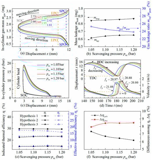
Figure 7.
The influence of scavenging pressure on leakage and system performance. (a) Mass variations of in-cylinder gas in function of stroke; (b) Mass leakage; (c) Pressure variations of in-cylinder gas in function of stroke; (d) Piston dynamic characeristics; (e) Thermal efficiencies; (f) Indicated thermal efficiency drops. Figure (a,c,d) apply the same legend displayed in figure (c). The blue, green, red and black solid lines stand for the scavenging pressures at 1.05, 1.10, 1.15 and 1.20 bar, respectively. The values in figure (a) show the exact amount of the in-cylinder gas mass at the corresponding positions. The symbol fp in figure (d) stands for piston frequency, Hz.
After the onset of the combustion, the piston moves backward from SOC to the exhaust port opening position (EPO), due to the high-pressure produce by the burning fuel. The in-cylinder gas still leaks nonlinearly during this period and the mass leakage is the mlexp. It can be calculated according to Equation (8). The value of mass leakages during the compression and expansion strokes is displayed in Figure 7b. It shows that the mlexp is greater than the mlcp, indicating a more serious mass leakage at the expansion stroke. This is because that the in-cylinder pressure rises rapidly due to the fuel combustion, as inferred in in Figure 7c, compared to the almost unchanged pressure on the other side of the piston. Therefore, the pressure difference between the two sides of the piston rod increases enormously, which deteriorates the mass leakage as can be inferred from Equation (7). Thus, the mass leaks asymmetrically with respect to the SOC.
The boosting of psc increases the mass flow at both scavenging and exhaust port simultaneously, but the increment decreases gradually. This observation means that there is a limit to the promoting effect of the scavenging pressure on the mass trapped in the cylinder, which is referred as a “saturated trend” here. The in-cylinder gas mass at SOC mgsoc shows a similar saturation trend, which explains the phenomenon of increment saturation of the in-cylinder peak pressure pmax shown in Figure 7c.
In terms of the mass leakage during the compression mlcp, as described in Equation (7), is the mass difference between the EPC and SOC. It increases from 0.61 mg to 0.65 mg as psc increases from 1.05 to 1.20 bar, as shown in Figure 7b. The reason is that the time consumed during the compression increases, which prolongs the time of leakage, and the elevated in-cylinder gas pressure, which increases the pressure difference between the two piston ends. However, the mass leak ratio mlcp/mgepc decreases, indicating a better sealing performance under higher the scavenging pressure condition.
As to the top dead centre (TDC), it increases slightly with the increase in psc, as shown in Figure 7d. This results in a gentle increase in the effective compression ratio εec, and therefore, a relatively higher combustion pressure to be compensated by the piston movement. Thus, the piston stroke increases and the bottom dead centre (BDC) expands. The geometric compression ratio εc increases accordingly. Since the enhanced in-cylinder pressure imposes more hindrance effect on the piston movement, the piston velocity v decreases more rapidly in the later stage of the compression stroke with the increase in scavenging pressure psc, as inferred from the shorter time elapsed from the maximum compression speed to zero velocity. The peak velocity vmax also rises with the increase in psc for the same reason. In addition, the piston frequency fp decreases with the increase in psc, which is a combined result of the enhanced in-cylinder pressure and prolonged piston stroke, which exert opposite effects on system stiffness.
As indicated from Figure 7e, the indicated thermal efficiency under Hypothesis 1 decreases slightly as psc increases, due to the reduced in-cylinder trapping efficiency φtrap. Under Hypothesis 2, since the reduced gas leakage ratio offsets the effect of φtrap decreasing, the corresponding ηi,b increases slightly. Therefore, the effect of leakage loss on the indicated thermal efficiency characterized Δηi,a-b = ηi,a − ηi,b decreases, shown in Figure 7f. Hypothesis 3 takes heat loss into consideration. The heat transfer across the cylinder wall is mainly determined by the in-cylinder gas temperature T and heat transfer time. Since the heat transfer mainly occurs in the expansion stroke, the expansion duration texp is thus considered as the heat transfer time. The gas temperature enhances with the increase in psc, while texp shrinks. Thus, in general, the effect of heat loss, characterized as Δηi,b-c = ηi,b − ηi,c increases at low psc and changes little at high psc.
The effective thermal efficiency is mainly affected by the indicated work Wi and three consumption works: the motoring work Wconsm, the pumping work Wpump and the frictional work Wf. With the boosting of psc, Wpump increases. Meanwhile, the extension of the piston stroke and the acceleration of the piston velocity lead to the rise of the Wconsm and the Wf, respectively. As a result, ηe,a decreases monotonously. With the contribution of positive increment of Wi in Hyp. B, ηe,b increases at first and starts to decay, while the increment of energy consumption is too large to offset, leading to a local extremum ηe,b at 1.15 bar. Since the variation of heat loss is slight, the effective thermal efficiency under Hyp. C ηe,c retains the same trend with ηe,b.
4.2. Effect of the Start of Combustion
In reality, the ignition time is controlled by adjusting the temperature of the glow plug and the SOC is characterized by the ignition position xign. In the simulation, the value of xign is varied from 1~4 mm, while all the other parameters remain unchanged. The increase in xign indicates the advancing of SOC and the decrease in xign means the delay of SOC.
According to Figure 8a, when the xign varies, the in-cylinder gas mass at EPC mgepc shows little difference, while the in-cylinder gas mass at SOC mgsoc varies largely. When the combustion takes place between 2~4 mm, mgsoc increases with the advance of SOC, whereas mgsoc decreases with the advancing of SOC after the piston is compressed less than 2 mm. The reason is that the piston frequency fp increases sharply with the delay of SOC, reduces the time of leakage and offsets the effect of the increase in pressure difference at this range. The corresponding leakage characteristics are presented in Figure 8b. In most cases, the mass leaked during the expansion stroke is more than that during the compression stroke. As seen from the mass leakage ratio curve, the leakage peaks at xign = 2 mm indicate that the worst sealing performance occurs there. Better sealing could be achieved either by advancing ignition time or postponing the ignition until the piston passes 2 mm.
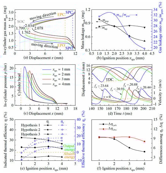
Figure 8.
The influence of ignition position on leakage and system performance. (a) Mass variations of in-cylinder gas in function of stroke; (b) Mass leakage; (c) Pressure variations of in-cylinder gas in function of stroke; (d) Piston dynamic characeristics; (e) Thermal efficiencies; (f) Indicated thermal efficiency drops. Figure (a,c,d) apply the same legend displayed in figure (c). The blue, green, red and black solid lines stand for the ignition positions at 1.0, 2.0, 3.0 and 4.0 mm, respectively. The values in figure (a) show the exact amount of the in-cylinder gas mass at the corresponding positions. The symbol fp in figure (d) stands for piston frequency, Hz.
The delay of SOC is realized by controlling the combustion that takes place closer to the cylinder head, so the effective compression ratio εec monotonically increases with the delay of SOC. The in-cylinder peak pressure pmax, on the other hand, varies more complexly, as shown in Figure 8c. When xign is in the range of 3~4 mm, pmax increases with the delay of SOC, as being straightforwardly influenced by the increased εec. When xign decreases to the range of 2~3 mm, the mass leakage exacerbates and overtakes the promoting effect of εec increase. Thus, the pmax decreases with a delay of SOC in this range. As xign further decreases to the range of 1~2 mm, pmax increases with the delay of SOC, again due to the combined effects of the increased εec and the aforementioned slight increase in mgsoc in this range.
As shown in Figure 8d, the more advanced the SOC, the farther the piston trajectory form the cylinder head. This means that the TDC and BDC deviate from the cylinder head further at the same time with the advancing of SOC. However, compared to the given range of SOC, the position difference of the BDC is little. Therefore, the geometric compression ratio εc decreases with the advancing of SOC. The variation of piston stroke S and peak piston velocity vmax show the same trend as pmax. Since the effect of pmax enhancement on system dynamic stiffness is partly counteracted by the effect of piston stroke S elongation, the piston frequency fp decreases with the advance of SOC, in general.
Figure 8e displays the predicted indicated and effective thermal efficiencies of the MFPG prototype. The ηi,a decreases with the advancing of SOC because of the relatively lower εec. The ηi,b obtains a local extremum at xign = 3 mm due to the opposite effect of the decrease in mass leak and reduction of εec. The ηi,c keeps the same trend with ηi,b and the heat loss Δηi,b-c also has a local extremum at xign = 3 mm as shown in Figure 8f. In addition, as the SOC timing advances, the in-cylinder gas force decreases exponentially. The consumption work of piston motoring drops accordingly. Thus, the effective thermal efficiencies, under the three hypotheses ηe,a, ηe,b, ηe,c, all increase with the advancing of the SOC. As indicated by the negative value of ηe,c the ignition position is less than 2 mm, the system is incapable of outputting energy at this range.
4.3. Effect of the Combustion Duration
Combustion duration tcd is an important parameter reflecting the combustion process. The tcd is varied from 2.5~4 ms in the simulation while all the other parameters are kept the same. As implied by Figure 9a,b, the curve of the in-cylinder gas during compression overlaps each other and the mass leak mlcp is nearly flat, meaning that the variation of tcd has no significant effect on the fuel loss. On the other hand, the mass of in-cylinder gas at exhaust port opening mgepo decreases with the extending of tcd, which means the mass leakage during expansion mlexp increases. Although the prolongation of tcd lowers the pmax, as shown in Figure 9c, which helps to reduce the mlexp, the increased expansion time texp is mainly responsible for the increase in mlexp.
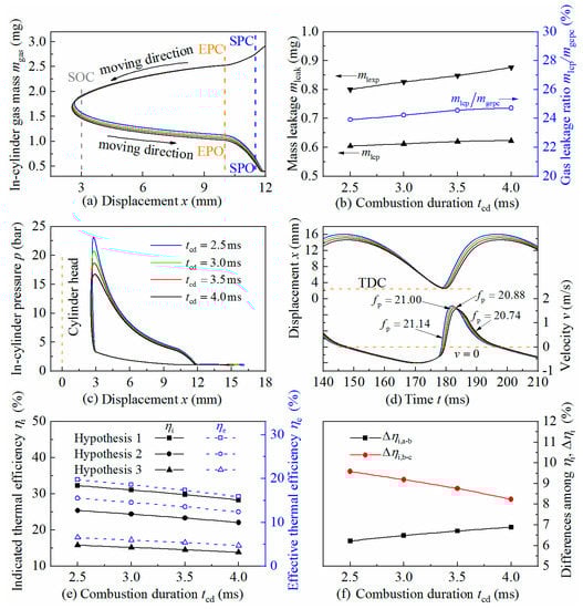
Figure 9.
The influence of combustion duration on leakage and system performance. (a) Mass variations of in-cylinder gas in function of stroke; (b) Mass leakage; (c) Pressure variations of in-cylinder gas in function of stroke; (d) Piston dynamic characeristics; (e) Thermal efficiencies; (f) Indicated thermal efficiency drops. Figure (a,c,d) apply the same legend displayed in figure (c). The blue, green, red and black solid lines stand for the combustion durations of 2.5, 3.0, 3.5 and 4.0 ms, respectively. The symbol fp in figure (d) stands for piston frequency, Hz.
With a shorter tcd, a system releases the heat in a shorter time, which is closer to the ideal Otto cycle. The pmax is therefore enhanced, as presented in Figure 9c. The TDC increases, as shown in Figure 9d, as a result of elevated in-cylinder gas pressure and the effective compression ratio εec hence decreases slightly. The BDC also increases due to the enhanced pmax. By taking the difference between the positions of TDC and BDC, the piston stroke S shows an increasing trend and so does the compression ratio εc. The increased piston peak velocity vmax and piston frequency fp are also the results of enhanced pmax.
Figure 9e shows that the indicated thermal efficiencies, under the three hypotheses, all increase monotonously with the reducing of combustion duration tcd, mainly due to the aforementioned higher degree of isochoric combustion. There are few effects of tcd on the three major consumption work, Wconsm, Wpump, and Wf, so the effective thermal efficiencies ηe,a, ηe,b and ηe,c show nearly the same trends with their corresponding indicated thermal efficiencies. The Δηi,a-b, which reflects the effect of leakage loss, decreases insignificantly with respect to the increase in tcd as implied by Figure 9f. The result is consistent with the aforementioned conclusion that tcd has no significant effect on mgsoc. The variation of tcd brings in two effects on heat loss. As tcd increases, the maximum combustion temperature Tmax decreases, which is beneficial for heat loss reduction. On the other hand, time consumed by expansion texp increases, which extends the heat transfer time and intensifies the heat loss. The Δηi,b-c, which reflects the effect of the heat loss, decreases slightly with respect to the prolongation of tcd, indicating that the influence of T on the heat loss is dominant in these cases.
4.4. Effect of the Piston Mass
Piston mass mp is another important factor affecting the natural frequency of the piston fp. The piston mass of the physical MFPG prototype is 156 g, so the adjusting range of mp is set to be 100~184 g with the other parameters unchanged. According to Figure 10a, the mass of the in-cylinder gas at EPC mgepc is almost the same in the four cases and so is the gas mass at SOC mgsoc, which means that the variation of mp has no significant effect on mlcp as directly presented in Figure 10b. This is mainly attributed to the insignificant differences of the in-cylinder gas pressure during combustion, as shown in Figure 10c, and nearly the same compression time tcp as implied by Figure 10d. During the expansion, the peak velocity vmax of the heavier piston is obviously lower than that of the light ones, which results in the extended time of expansion texp and leads to the enlarged mass leakage mlexp in this range.
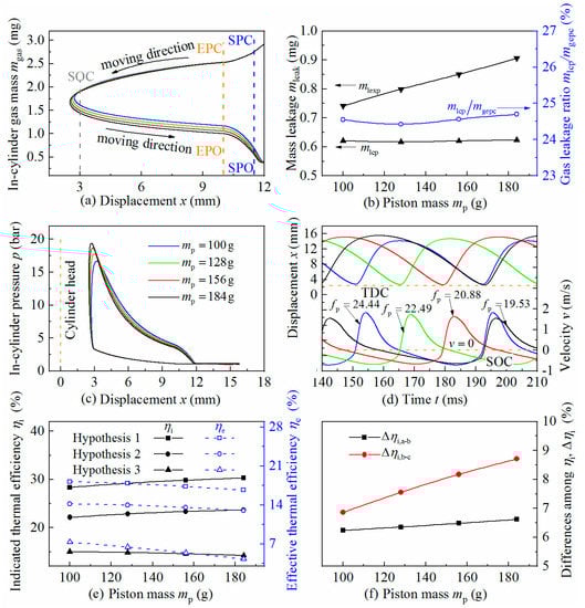
Figure 10.
The influence of piston mass on leakage and system performance. (a) Mass variations of in-cylinder gas in function of stroke; (b) Mass leakage; (c) Pressure variations of in-cylinder gas in function of stroke; (d) Piston dynamic characeristics; (e) Thermal efficiencies; (f) Indicated thermal efficiency drops. Figure (a,c,d) apply the same legend displayed in figure (c). The blue, green, red and black solid lines stand for the piston mass of 100, 128, 156 and 184 mm, respectively. The symbol fp in figure (d) stands for piston frequency, Hz.
Figure 10c indicates that mp has little effect on the in-cylinder gas pressure during the compression. However, pmax increases when a heavier piston is applied, which is mainly attributed to the increased effective compression ratio εec, since the mass of the in-cylinder gas at SOC mgsoc is almost the same and hardly affects the pmax. The heavier the piston, the closer the TDC with respect to the cylinder head, so the εec increases accordingly and promotes the pmax. In addition, the inertia effect becomes more pronounced with the increase in mp, the piston, therefore, responds slowly when expansion. Thus, the degree of isovolumetric combustion is hence increased and further enhances the pmax. It is notable that the heavier the piston, the faster the in-cylinder gas pressure decreases in the expansion stroke, which is due to the more severe leakage of mlexp with increase in the piston mass.
As the piston mass increases, the piston stops farther with a larger value of BDC, as is indicated in Figure 10d. This is because the heavier piston leads to higher pmax, which produces more work and needs a longer distance to offset. For the heavier pistons, the longer BDC implies increased acceleration length in the next cycle and therefore the higher speed at SOC. The piston kinetic energy is, therefore, greater and the piston is closer to the cylinder head, resulting in a decrease in TDC. Hence, the piston stroke S and compression ratio εc both increase accordingly. In contrast, when the pistons expand back towards the BDC, all the pistons start at almost the same position, so the advantage of acceleration distance for the heavier pistons disappears and results in lower vmax. It is known that the natural frequency is inversely proportional to the square root of the mass, thus the piston frequency fp decreases as the piston mass increases.
The effective compression ratio εec and the degree of isochoric combustion both increase with an increase in the piston mass, so the ηi,a increases, as presented in Figure 10e. The ηi,b keeps the same trend with ηi,a because the fuel leakage indicator mlcp is little affected by the variation of mp. The change of Δηi,a-b, shown in Figure 10f, is therefore unobvious. The increase Δηi,b-c indicates an aggravated heat loss due to the prolonged expansion stroke and enhances combustion temperature for heavier pistons. In terms of effective thermal efficiency, the elongated piston stroke S for the heavier piston consumes more electric energy Wconsm during the compression. The increment of Wi is not enough to compensate the Wconsm, so the net output power Wnet reduces and leads to a decrease in ηe for all the cases. The influence of leakage and heat transfer on ηe is about the same as that on ηi, so the three effective thermal efficiencies ηe,a, ηe,b and ηe,c all decrease monotonously as the mp increases.
4.5. Parameter Optimization
The piston dynamics of the MFPG system are more complexed than that of traditional micro ICEs and different combinations of system parameters define different performances of an MFPG system. Table 2 summarizes the influences of the controllable external parameters on the performance of the MFPG prototype.
Table 2.
Influences of parameters on the MFPG performance.
Based on that, a set of optimal parameter combinations was preliminarily determined, which is listed in Table 2, as well. The 1.15 bar of scavenging pressure and 3 mm of SOC are selected because they correspond to the local extremum of the thermal efficiencies. The combustion duration is controlled by chemical reaction kinetics and is hard to obtain. When 3.5 ms is chosen, the simulation best approximates the experimental results. A lightweight piston is more favorable in improving thermal efficiency. Its high operation frequency, however, poses more challenges to the design of the control system. For this reason, the first generation of MFPG prototype chooses a relatively larger piston mass, which is about 156 g, to compromise the control system.
5. Power Flow and Energy Distribution
In order to predict the optimal energy conversion efficiency of the proposed MFPG, the optimum values listed in Table 2 are applied in the power and energy calculations of the MFPG. Figure 11 shows the transient powers of the major forces within an entire cycle. The positive power represents that the piston absorbs power from the external force, whereas the negative power indicates that the piston outputs power to the external force. The shadowed areas are the works performed by the corresponding forces.

Figure 11.
Simulations of the transient powers of the forces imposed on the piston in a complete cycle.
The simulation starts from the BDC. In the second half of the scavenging stroke, the voice coil motor drives the piston from BDC to exhaust port closing (EPC). The electromagnetic force transfers its power into the piston, so the power of electromagnetic force Pele is positive during this period. At the same time, the in-cylinder gas power Pp and frictional power Pf are relatively minor due to the lower scavenging pressure and piston velocity. Thus, only a small portion of Pele is used to balance the Pp and Pf and the major portion of the Pele is converted to the kinetic energy of the piston, which is the inertial power of piston Pa.
In the compression stroke, from the exhaust port closing to top dead center, the VCM continues to accelerate the piston and outputs positive work. The positive Pele is divided into three parts to compensate the piston inertia power Pa, to overcome the friction power Pf and to compress the in-cylinder gas Pp. In the later stage of the compression stroke, the in-cylinder gas pressure increases exponentially, so Pele is not enough to maintain the acceleration of the piston. Thus, the piston decelerates and the inertia power Pa, stored as kinetic energy of the piston, is released. After all of the Pa is converted into the compression power of the in-cylinder gas Pp, the piston stops. After the onset of combustion, the gas pressure in the cylinder increases sharply and leads to a small spike between SOC and TDC on the Pa and Pp curves. Furthermore, the inertia power Pa balances within the range from BDC to TDC. That means that the areas on the two sides of the abscissa before TDC are equal. This indicates that Pa is only an intermediate state, used for the temporary storage of excessive power of Pele, while the ultimate states of the power conversion are between Pele and Pp.
In the expansion stroke, the in-cylinder gas starts to work on the piston and pushes the piston towards the BDC, so the value of Pp is positive. After overcoming the frictional power Pf and the electromagnetic power Pele, the residual power is stored in the piston in the form of Pa. As the piston moves further, the in-cylinder pressure drops and the gas power Pp becomes insufficient to generate more Pele. Then, the piston slows down to release the stored Pa power and becomes another source of Pele. Thus, the value of Pa is negative. When the piston moves from EPO back to BDC, the Pp is further reduced. The Pa is responsible for overcoming the frictional power Pf and supplying the electric power generation at the same time. The power flow of the entire working cycle of the MFPG system indicates that the energy conversion of the system is a complex dynamic balance of different powers. The two ultimate power states in the process are Pele and Pp. When they are not balanced, their residual power is stored temporarily in the form of Pa.
It is assumed that the major energy loss of the MFPG system includes the short-cut loss Qscut caused by scavenging, heat transfer loss Qw across the cylinder wall, fuel leakage loss Qlcp through the piston–cylinder gap, the friction loss Wf between the moving/stationary units and mechanical loss Wpump for boosting the scavenging pressure. Based on this assumption, the energy distribution per cycle for this example is predicted and listed in Table 3.
Table 3.
Energy flow distribution per cycle in the MFPG prototype.
The optimal parameters result in a compression ratio of 5.6. The friction loss takes up 17.9% out of the indicated work. About 82.1% of the indicated work is converted to the gross electric energy by the VCM, 34.71% of which is consumed to drive the piston from BDC to TDC in the next cycle, and 19.78% is used for the boosting of scavenging pressure. Only 45.51% of the gross electric energy is output as net electric energy. Therefore, the resulting effective energy efficiency is 5.7%. Assuming that the mechanical-electro conversion efficiency of the VCM is about 90%, the total chemical to electric energy conversion efficiency is about 5.13% for the proposed MFPG prototype. The operating frequency of the prototype is around 20~24 Hz, which is equivalent to 1200~1440 rpm, the MFPG prototype outputs a power of 10~13 W, with a power density around 4.7~5.7 W/cc.
6. Conclusions
This work centers on the influences of the system parameters on characteristics of the in-cylinder mass leakage and the corresponding system performance. The effects of scavenging pressure, ignition position, combustion duration and piston mass are investigated. A sample power flow and energy distribution are analyzed to understand the pattern of energy conversion in the MFPG prototype.
(1) The leakage loss is closely related to the mass leakage during the compression mlcp, which increases with increased scavenging pressure psc. The combustion duration tcd and piston mass mp have little effect on the mlcp. With the advancing of the onset of combustion, mlcp maximizes at xign = 2 mm. The effect of leakage loss on the indicated thermal efficiency Δηi,a-b can be straightforwardly inferred by the gas leakage ratio mlcp/mgecp.
(2) The indicated thermal efficiency ηi,c can be improved by boosting the scavenging pressure psc, whereas the increase in combustion duration tcd and piston mass mp deteriorates the ηi,c. The optimal position of SOC for the higher ηe,c is around 3 mm. The effective thermal efficiency ηe,c decreases monotonously with the delay of SOC and the MFPG system is incapable to output power when the xign is less than 2 mm.
(3) The piston mass mp has the most significant effect on the operation frequency fp and peak piston velocity vmax. The TDC and effective compression ratio εec are most sensitive to the change of SOC. The promotion effect of psc boosting on the in-cylinder peak pressure pmax and indicated thermal efficiency ηi,c has a “saturated trend”.
(4) During the entire working cycle, the powers of the MFPG system are dynamically conserved and circulate among each other. The frictional power Pf absorbs energy from the piston all the time. When the transient states of the two ultimate power states Pele and Pp are not balanced, the residual power is stored temporarily in the form of Pa.
Author Contributions
Conceptualization, S.Y.; methodology and software, W.W. and H.W.; funding acquisition and writing—original draft preparation, S.Z.; funding acquisition and conceptualization, C.Z.; writing—review and editing, Y.L. All authors have read and agreed to the published version of the manuscript.
Funding
This research was funded by The China Postdoctoral Science Foundation, grant number 2019M660484, also by The Shandong Postdoctoral Science Foundation, grant number 202003067 and The Fundamental Research Funds for the Central Universities (CHD), grant number 300102220506.
Institutional Review Board Statement
Not applicable.
Informed Consent Statement
Not applicable.
Data Availability Statement
Not applicable.
Conflicts of Interest
The authors declare no conflict of interest. The funders had no role in the design of the study; in the collection, analyses, or interpretation of data; in the writing of the manuscript, or in the decision to publish the results.
Nomenclature and Abbreviations
The following nomenclature and abbreviations are used in this manuscript:
| Aleak | Leakage area of the piston–cylinder unit, m2 |
| Aw | Effective area of heat transfer, m2 |
| AFmeth | Air–Fuel Ratio of methanol |
| D | Bore diameter, m |
| Ff | Frictional force, N |
| Fele | Electromagnetic force of the VCM, N |
| Fgas | Gas force inside the combustion chamber, N |
| fp | Piston frequency, Hz |
| Hu | Lower heating value, KJ/kg |
| imotor | Motoring current, A |
| iout | Output current, A |
| kmotor | Motor Constant, N/A |
| kemf | Back EMF constant, V/m/s−1 |
| Ls | Motor inductance, H |
| m | Combustion quality factor |
| mfuel | Mass of the fuel supplied per cycle, kg |
| mgepc | Mass of the in-cylinder gas at EPC, kg |
| mgepo | Mass of the in-cylinder gas at EPO, kg |
| mgsoc | Mass of the in-cylinder gas at SOC, kg |
| mlcp | Mass of the leaked gas during the compression, kg |
| mleak | Mass of the leaked gas in a complete cycle, kg |
| mlexp | Mass of the leaked gas during the expansion, kg |
| mp | Piston mass, kg |
| p | In-cylinder gas pressure, Pa |
| pEPC | In-cylinder gas pressure at the EPC, Pa |
| pmax | Peak pressure of in-cylinder gas, Pa |
| psc | Scavenging pressure, Pa |
| pI, pII | Upstream and downstream pressures of the throttling orifice, Pa |
| Pa | Inertial power, W |
| Pele | Electromagnetic power, W |
| Pf | Frictional power, W |
| Pp | In-cylinder gas power, W |
| Qfuel | Heat input through scavenging port, J |
| Qscut | Short cut loss form exhaust port, J |
| Qlcp | Leakage loss through the piston–cylinder gap, J |
| Qw | Heat loss across cylinder wall, J |
| Rs | Motor resistance, Ω |
| S | Piston stroke, m |
| T | In-cylinder gas temperature, K |
| TEPC | In-cylinder gas temperature at the EPC, K |
| Tsc | Scavenging temperature, K |
| Tw | Wall temperature, K |
| tcd | Combustion duration, s |
| tcp | Compression duration, s |
| texp | Expansion duration, s |
| V | In-cylinder gas volume, m3 |
| VEPC | In-cylinder gas volume at the EPC, m3 |
| Vh | Swept volume, m3 |
| vmax | Max piston velocity, m/s |
| Wi | Indicated work, J |
| Wf | Friction loss, J |
| Wgen | Gross electric energy generation, J |
| Wpump | Scavenging loss, J |
| Wconsm | Motoring energy, J |
| Wnet | Net electric energy, J |
| x | Piston displacement, m |
| xtlim | Top limit position, m |
| xblim | Bottom limit postion, m |
| xign | Ignition position, m |
| xEPO | Exhaust port opening, m |
| xEh | Exhaust port height, m |
| xSPO | Scavenging port opening, m |
| xSh | Scavenging port height, m |
| aw | Convective heat transfer coefficient, W/(m2·K) |
| γ | Adiabatic exponent |
| Δηe,a-b | Effective thermal efficiency loss caused by leakage |
| Δηe,b-c | Effective thermal efficiency loss caused by heat transfer |
| Δηi,a-b | Indicated thermal efficiency loss caused by leakage |
| Δηi,b-c | Indicated thermal efficiency loss caused by heat transfer |
| εc | Geometry compression ratio |
| εec | Effective compression ratio |
| ηe | Effective thermal efficiency |
| ηe,a, ηe,b, ηe,c | Effective thermal efficiency of Hypothesis 1, Hypothesis 2, Hypothesis 3 |
| ηi | Indicated thermal efficiency; |
| ηi,a, ηi,b, ηi,c | Indicated thermal efficiency of Hypothesis 1, Hypothesis 2, Hypothesis 3 |
| ρI, ρII | Upstream and downstream densities of the throttling orifice, kg/m3 |
| φs | Scavenging efficiency |
| φtrap | Trapping efficiency of the in-cylinder gas |
| μcdl | Discharge coefficient of the leakage passage |
| Ψlsub, Ψlsup | Subsonic and supersonic flow functions of the in-cylinder gas leakage |
| BDC | Bottom dead center |
| CR | Compression ratio |
| EPC | Exhaust port closing |
| EPO | Exhaust port opening |
| EGR | Exhaust gas recirculation |
| Exp. | Experiment data |
| ICE | Internal combustion engine |
| MFPG | Miniature free-piston generator |
| SC-Batt ES | Super capacitor–battery energy storage |
| Sim. | Simulation data |
| SOC | Start of combustion |
| SPC | Scavenging port closing |
| SPO | Scavenging port opening |
| TDC | Top dead center |
| VCM | Voice coil motor |
References
- Lallart, M.; Yan, L.; Miki, H.; Sebald, G.; Kohl, M. Heusler alloy-based heat engine using pyroelectric conversion for small-scale thermal energy harvesting. Appl. Energy 2021, 288, 116617. [Google Scholar] [CrossRef]
- Tarascon, J.M.; Armand, M. Issues and challenges facing rechargeable lithium batteries. Nature 2001, 414, 359367. [Google Scholar] [CrossRef] [PubMed]
- Maurya, D.; Kumar, P.; Khaleghian, S.; Sriramdas, R.; Kang, M.G.; Kishore, R.A.; Kumar, V.; Song, H.C.; Park, J.M.; Taheri, S. Energy harvesting and strain sensing in smart tire for next generation autonomous vehicles. Appl. Energy 2018, 232, 312–322. [Google Scholar] [CrossRef]
- Burugupally, S.; Weiss, L. Power Generation via Small Length Scale Thermo-Mechanical Systems: Current Status and Challenges, a Review. Energies 2018, 11, 2253. [Google Scholar] [CrossRef] [Green Version]
- Lei, Y.; Chen, W.; Lei, J. Combustion and direct energy conversion in a micro-combustor. Appl. Therm. Eng. 2016, 100, 348–355. [Google Scholar] [CrossRef]
- Walther, D.C.; Ahn, J. Advances and challenges in the development of power-generation systems at small scales. Prog. Energy Combust. Sci. 2011, 37, 583–610. [Google Scholar] [CrossRef]
- D’Souza, R.; Sharma, R.N. An Experimental Study of an Ultra-Micro Scale Gas “Turbine”. Appl. Therm. Eng. 2019, 163, 114349. [Google Scholar] [CrossRef]
- Annen, K.; Stickler, D.; Woodroffe, J. Miniature internal combustion engine-generator for high energy density portable power. In Proceedings of the Army Science Conference (26th), Orlando, FL, USA, 1–4 December 2008. [Google Scholar]
- Ding, Y.; Zhao, Y.; Yu, G. A membrane-free ferrocene-based high-rate semiliquid battery. Nano Lett. 2015, 15, 4108–4113. [Google Scholar] [CrossRef] [PubMed]
- Epstein, A.H. Millimeter-Scale, Micro-Electro-Mechanical Systems Gas Turbine Engines. J. Eng. Gas. Turbines Power 2004, 126, 205–226. [Google Scholar] [CrossRef]
- Shah, R.R.; Kulshreshtha, D.B.; Shah, P.D. Experimental Studies on Recuperative Micro-Combustion Chamber for 1 W Gas Turbine Engine. J. Inst. Eng. India Ser. C 2020, 101, 785–792. [Google Scholar] [CrossRef]
- Badum, L.; Leizeronok, B.; Cukurel, B. New Insights From Conceptual Design of an Additive Manufactured 300 W Micro Gas Turbine Towards UAV Applications. In Proceedings of the ASME Turbo Expo 2020: Turbomachinery Technical Conference and Exposition, London, UK, 22–26 June 2020. [Google Scholar]
- Lv, X.; Zeng, W.; Ding, X.; Weng, Y.; Weng, S. Experimental investigation of a novel micro gas turbine with flexible switching function for distributed power system. Front. Energy 2020, 14, 790–800. [Google Scholar] [CrossRef]
- Yang, L.J.; Kang, S.W. An ultra-small Wankel engine by MEMS process. In Proceedings of the 10th International Heat Pipe Symposium, Taibei, Taiwan, 6–9 November 2011. [Google Scholar]
- Melnarowicz, W. Wankel Engines for Unmanned Aerial Vehicles. J. Konbin 2017, 44, 267–274. [Google Scholar] [CrossRef] [Green Version]
- Zhang, Y.; Liu, J.; Zuo, Z.; Zhang, S. Optimization of volumetric efficiency of a small wankel engine using genetic algorithm. Therm. Sci. 2019, 24, 58. [Google Scholar] [CrossRef] [Green Version]
- Wang, Y. Study on the Effect of Heat Transfer on the Performance of Micro Swing Engine. Ind. Heat. 2019, 48, 5–8. [Google Scholar]
- Zhang, Z.G.; Xia, C.; Huang, G.P.; Shen, L.F.; Xu, Y. Analysis on the heat-recuperable hybrid cycle for micro swing engine with a non-isometric multi-chamber structure. Sci. Sin. Technol. 2019, 49, 378–390. [Google Scholar] [CrossRef]
- Bo, S.; Hai, Y.; Jin, Z. The effects of the various factors and the engine size on micro internal combustion swing engine (MICSE). Appl. Therm. Eng. 2018, 144, 262–268. [Google Scholar]
- Lungu, C.E.; Disseau, M.; Stubbs, D.C.; Jagoda, J.; Scarborough, D. An experimental and theoretical investigation of a small, high aspect-ratio, free-piston, two-stroke engine. Propuls. Power Res. 2020, 9, 326–343. [Google Scholar] [CrossRef]
- Huang, F.; Kong, W. Experimental study on the operating characteristics of a reciprocating free-piston linear engine. Appl. Therm. Eng. 2019, 161, 114131. [Google Scholar] [CrossRef]
- Johnson, D.L. Miniature Free-Piston Engine Compressor. Master’s Thesis, University of Minnesota, Minneapolis, MN, USA, 2015. [Google Scholar]
- Wang, Q.; Wu, F.; Zhao, Y.; Bai, J.; Huang, R. Study on combustion characteristics and ignition limits extending of micro free-piston engines. Energy 2019, 179, 805–814. [Google Scholar] [CrossRef]
- Chen, J.Y.; Chen, M.Y. Steam Micro Turbine Engine. U.S. Patent 2018/0080375 A1, 22 March 2018. [Google Scholar]
- Kim, C.K.; Yoon, J.Y. Performance analysis of bladeless jet propulsion micro-steam turbine for micro-CHP (combined heat and power) systems utilizing low-grade heat sources. Energy 2016, 101, 411–420. [Google Scholar] [CrossRef]
- Balanescu, D.T.; Homutescu, V.M.; Popescu, A. Micro gas and steam turbines power generation system for hybrid electric vehicles. IOP Conf. Ser. Mater. Sci. Eng. 2018, 444, 082022. [Google Scholar] [CrossRef]
- Preetham, B.S.; Anderson, M.; Richards, C. Mathematical modeling of a four-stroke resonant engine for micro and mesoscale applications. J. Appl. Phys. 2014, 116, 422–520. [Google Scholar] [CrossRef]
- Strano, M.S.; Cottrill, A.L.; Mahajan, S.G.; Liu, T.; Koman, V.B. Materials, Devices, and Methods for Resonant Ambient Thermal Energy Harvesting. U.S. Patent 2019/0063412 A1, 28 February 2019. [Google Scholar]
- Guo, C.; Zuo, Z.; Jia, B.; Zhang, Z.; Roskilly, A.P. Parametric analysis of a dual-piston type free-piston gasoline engine linear generator. Energy Procedia 2019, 158, 1431–1436. [Google Scholar]
- Wu, W.; Hu, J.; Yuan, S. Semi-analytical modelling of a hydraulic free-piston engine. Appl. Energy 2014, 120, 75–84. [Google Scholar] [CrossRef]
- Guo, C.; Zuo, Z.; Feng, H.; Roskilly, T. Advances in free-piston internal combustion engines: A Comprehensive Review. Appl. Therm. Eng. 2021, 189, 116679. [Google Scholar] [CrossRef]
- Hu, J.; Wu, W.; Yuan, S.; Jing, C. Fuel combustion under asymmetric piston motion: Tested results. Energy 2013, 55, 209–215. [Google Scholar] [CrossRef]
- Aichlmayr, H.T.; Kittelson, D.B.; Zachariah, M.R. Miniature free-piston homogeneous charge compression ignition engine-compressor concept—Part I: Performance estimation and design considerations unique to small dimensions. Chem. Eng. Sci. 2002, 57, 4161–4171. [Google Scholar] [CrossRef]
- Aichlmayr, H.T.; Kittelson, D.B.; Zachariah, M.R. Miniature free-piston homogeneous charge compression ignition engine-compressor concept—Part II: Modeling HCCI combustion in small scales with detailed homogeneous gas phase chemical kinetics. Chem. Eng. Sci. 2002, 57, 4173–4186. [Google Scholar] [CrossRef]
- Suzuki, Y.; Okada, Y.; Ogawa, J.; Sugiyama, S.; Toriyama, T. Experimental study on mechanical power generation from MEMS internal combustion engine. Sens. Actuators A 2008, 141, 654–661. [Google Scholar] [CrossRef]
- Lee, D.H.; Park, D.E.; Yoon, J.B.; Kwon, S.; Yoon, E. Fabrication and test of a MEMS combustor and reciprocating device. J. Micromech. Microeng. 2001, 12, 26. [Google Scholar] [CrossRef]
- Tian, L. Miniature Homogeneous Charge Compression Ignition Free-Piston Engine Compressor; University of Minnesota: Minneapolis, MN, USA, 2013. [Google Scholar]
- Sher, E.; Sher, I. Theoretical limits of scaling-down internal combustion engines. Chem. Eng. Sci. 2011, 66, 260–267. [Google Scholar] [CrossRef] [Green Version]
- Wang, W.; Zuo, Z.; Liu, J. Miniaturization limitations of rotary internal combustion engines. Energy Convers. Manage. 2016, 112, 101–114. [Google Scholar] [CrossRef]
- Annen, K.; Stickler, D.; Woodroffe, J. Linearly-Oscillating Miniature Internal Combustion Engine (MICE) for Portable Electric Power. In Proceedings of the AIAA Aerospace Sciences Meeting and Exhibit, 41th, Reno, NV, USA, 6–9 January 2003. [Google Scholar]
- Sugiyama, S.; Toriyama, T. Design of a micro reciprocating engine for power generation. IEEJ Trans. Sens. Micromach. 2003, 123, 351–356. [Google Scholar] [CrossRef] [Green Version]
- Yang, W. Liquid piston chip engine. In Proceedings of the DARPA/MTOMEMS-/MPG/NMASP, Principal Investigators’ Meeting, Bloomington, CO, USA, 15 February 2001. [Google Scholar]
- Sun, M.; Zhang, Z.Y.; Kong, W.J. Design of Sealing Structure and Analysis of the Flow Field in Micro Internal Combustion Swing Engine. Appl. Mech. Mater. 2014, 670, 930–935. [Google Scholar] [CrossRef]
- Salleh, H.; Khalid, A.; Sulaiman, S.; Manshoor, B.; Razzaly, W. Effects of Fluid Flow Characteristics and Heat Transfer of Integrated Impingement Cooling Structure for Micro Gas Turbine. CFD Lett. 2020, 12, 104–115. [Google Scholar] [CrossRef]
- Wu, Y.Y.; Chen, B.C.; Hsieh, F.C.; Ke, C.T. Heat transfer model for small-scale spark-ignition engines. Int. J. Heat Mass Transfer 2009, 52, 1875–1886. [Google Scholar] [CrossRef]
- Drost, M.K.; Call, C.; Wegeng, R. Microchannel Combustor/Evaporator Thermal Processes. Microscale Thermophys. Eng. 1997, 1, 321–332. [Google Scholar]
- Hua, J.; Wu, M.; Kumar, K. Numerical simulation of the combustion of hydrogen-air mixture in micro-scaled chambers. Part I: Fundamental study. Chem. Eng. Sci. 2005, 60, 3497–3506. [Google Scholar] [CrossRef]
- Zhou, Y.; Sofianopoulos, A.; Gainey, B.; Lawler, B.; Mamalis, S. A system-level numerical study of a homogeneous charge compression ignition spring-assisted free piston linear alternator with various piston motion profiles. Appl. Energy 2019, 239, 820–835. [Google Scholar] [CrossRef]
- Kim, J.; Bae, C.; Kim, G. Simulation on the effect of the combustion parameters on the piston dynamics and engine performance using the wiebe function in a free piston engine. Appl. Energy 2013, 107, 446–455. [Google Scholar] [CrossRef]
- Zhang, S.; Lee, T.H.; Wu, H.; Pei, J.; Wu, W.; Liu, F. Experimental and Kinetical Study of Component Volumetric Effects on Laminar Flame Speed of Acetone-Butanol-Ethanol (ABE). Energy Fuels 2018, 32, 6278–6292. [Google Scholar] [CrossRef]
- Deng, B.; Li, Q.; Chen, Y.; Li, M.; Liu, A.; Ran, J.; Xu, Y.; Liu, X.; Fu, J.; Feng, R. The effect of air/fuel ratio on the CO and NOx emissions for a twin-spark motorcycle gasoline engine under wide range of operating conditions. Energy 2019, 169, 1202–1213. [Google Scholar] [CrossRef]
- Zhang, S.; Lee, T.H.; Wu, H.; Pei, J.; Wu, W.; Liu, F.; Zhang, C. Experimental and kinetic studies on laminar flame characteristics of acetone-butanol-ethanol (ABE) and toluene reference fuel (TRF) blends at atmospheric pressure. Fuel 2018, 232, 755–768. [Google Scholar] [CrossRef]
- Li, X.; Zhen, X.; Wang, Y.; Liu, D.; Tian, Z. The knock study of high compression ratio SI engine fueled with methanol in combination with different EGR rates. Fuel 2019, 257, 116098. [Google Scholar] [CrossRef]
- Kosaka, H.; Akita, T.; Goto, S.; Hotta, Y. Development of free piston engine linear generator system and a resonant pendulum type control method. Int. J. Engine Res. 2020, 3, 146808742093124. [Google Scholar] [CrossRef]
- Hu, J.; Wu, W.; Yuan, S.; Jing, C. Mathematical modelling of a hydraulic free-piston engine considering hydraulic valve dynamics. Energy 2011, 36, 6234–6242. [Google Scholar] [CrossRef]
- Li, Q.; Jin, X.; Zhen, H. Simulation of a Two-Stroke Free-Piston Engine for Electrical Power Generation. Energy Fuels 2008, 22, 3443–3449. [Google Scholar] [CrossRef]
- Ozcan, H.; Zamfirescu, C.; Dincer, I.; Hariri, S.; Hariri, A.A. Transient modeling of a gas-liquid piston-cylinder mechanism for low temperature energy conversion applications. Int. J. Therm. Sci. 2017, 111, 525–532. [Google Scholar] [CrossRef]
- Woschni, G. A universally applicable equation for the instantaneous heat transfer coefficient in the internal combustion engine. SAE Tech. Pap. 1967, 670931, 1–11. [Google Scholar]
- Hohenberg, G.F. Advanced approaches for heat transfer calculations. SAE Tech. Pap. 1979, 790825, 2788–2806. [Google Scholar]
- Liu, G.; Liu, D. Simultaneous reconstruction of temperature and concentration profiles of soot and metal-oxide nanoparticles in asymmetric nanofluid fuel flames by inverse analysis. J. Quant. Spectrosc. Radiat. Transf. 2018, 219, 174–185. [Google Scholar] [CrossRef]
- Chen, H.; Hou, Y.; Wang, X.; Pan, Z.; Xu, H. Characterization of in-cylinder combustion temperature based on a flame-image processing technique. Energies 2019, 12, 2386. [Google Scholar] [CrossRef] [Green Version]
- Xiong, Z.; Zhang, Z.; Kong, W.; Du, N. Investigations of leakage mechanisms and its influences on a micro swing engine considering rarefaction effects. Appl. Therm. Eng. 2016, 106, 674–680. [Google Scholar]
Publisher’s Note: MDPI stays neutral with regard to jurisdictional claims in published maps and institutional affiliations. |
© 2021 by the authors. Licensee MDPI, Basel, Switzerland. This article is an open access article distributed under the terms and conditions of the Creative Commons Attribution (CC BY) license (https://creativecommons.org/licenses/by/4.0/).