Article

Dynamics of the Vibration System Driven by Three Homodromy Eccentric Rotors Using Control Synchronization

School of Control Engineering, Northeastern University at Qinhuangdao, Qinhuangdao 066004, China
*
Author to whom correspondence should be addressed.
Appl. Sci. 2021, 11(16), 7691; https://doi.org/10.3390/app11167691
Submission received: 28 June 2021 / Revised: 20 August 2021 / Accepted: 20 August 2021 / Published: 21 August 2021
(This article belongs to the Section Mechanical Engineering)

Abstract

:
To solve the limitation of vibration synchronization, this paper investigates the dynamics of a vibration system driven by three homodromy eccentric rotors (ERs) using control synchronization. According to the synchronous condition and the stability condition, the changes of the phase differences of the three-ERs system and the two-third ERs system are obtained. Based on the electromechanical mathematic model of the vibration system and the master-slave control strategy, the synchronous target that three ERs achieve the same phase motion is converted into velocity and phase tracking of ERs. Considering the coupling characteristic of the self-adjusting of the system in the state of vibration synchronization, the velocity and phase controllers are designed by employing discrete-time sliding mode control. An experimental system for control synchronization is designed, including hardware composition and software programming. For the feedback signal used to match control targets, a method of calculating velocity and the phase difference is proposed from engineering. Recording the rotational velocities, phase differences, and system response, three group experiments with different control schemes are achieved. According to the experimental data, the coupling characteristic of the vibration system adopting control synchronization is analyzed, which can provide the basis for designing vibration machines using control synchronization.

1. Introduction

Self-synchronization of the vibration system (vibration synchronization) is a special non-linear phenomenon first discovered by Huygens. Since then, vibration synchronization has attracted the great interest of many scholars, who study it from all aspects including eccentric rotors (ERs) and pendulums [1,2,3,4,5,6,7,8]. In these research results, synchronization of ERs is of great significance in engineering and technology fields, which is used to design vibration machines [9,10,11,12]. When it comes to the research of synchronization in a vibration system, Blekhman [2,9] was the first to explain the synchronization mechanism of two ERs theoretically by applying the method of the direct separation of motions. Based on this method, Zhao [8,10] proposed the average method of the modified small parameter to study synchronization of two ERs with opposite directions of plane motion, and obtain the condition of synchronization and its stability condition. Based on the average method of the modified small parameter, synchronization theories of two ERs with the same rotational direction of plane motion [11], that with the cross axis of spatial motion [10], and that with the same axis of spatial motion [12] are obtained separately, and can be applied successfully in engineering.
Although a vibration machine introduces vibration synchronization to replace the method of forced synchronization such as gears or chains, the application of vibration synchronization is still limited by its structural parameters [11,13]. When the number of ERs exceeds two, there is no the same phase (in-phase) motion between the rotors. From the perspective of power, only when ERs are operating in the synchronous motion of the same phase is their resultant force the largest. However, it is difficult to achieve the synchronous motion of ERs with the same phase by applying the technology of vibration synchronization, because the synchronization state is limited by the stability condition [11,12]. Meanwhile, forced synchronization is no longer the best choice to achieve the synchronous motion of ERs with the same phase. To achieve the purpose of power maximization, the idea of control synchronization applying in the vibration system is proposed by introducing the control method into synchronous research [9,14].
At present, the control strategy of multi-motors is mainly focused on several methods, such as master-slave control [14,15,16], cross-coupling control [17,18], virtual shaft control [19], ring coupling control [20], and so on. From the view of calculative complexity and the hardware system, the master-slave control is the most direct and effective method compared with other methods. Because the vibration system has coupling dynamic characteristics such as the Sommerfeld effect [21], its control synchronization is different from those of other mechanical systems [15,22,23]. For this type of non-linear system, the most commonly used control algorithm is PID control [5,24], the sliding mode control (SMC) [14,15,16], adaptive feed forward control [15,20,25], and so on.
To satisfy the requirements of the maximum resultant force of the vibration machine, several scholars studied control synchronization of the vibration system. Kong [14] proposed a method of control synchronization employing SMC on ERs, which numerically proves the feasibility of the control method. Adopting PI control, Tomchina [24] investigated control synchronization of two ERs in one degree of freedom vibration system. Jia [26] proposed a fuzzy PID method to investigate the multiple-frequency synchronization of ERs in the vibration system. Applying two PI algorithms separately, Fradkov [27] studied the multiple control synchronization for a three-rotor vibration unit with varying payload. Miklos [5] studied control synchronization of dual rotors in the vibration system by applying PI control, which is used to achieve independent adjustment between frequency and amplitude.
To sum up, the above scholars’ research results promote the development of control synchronization of the vibration system. However, introducing a control system into the vibration system will affect its original equilibrium state. How the stable state of the vibration system will change has not yet been studied, especially in experimental research. The lack of experimental research of the coupling characteristic of the vibration system still limits the engineering application of control synchronization. Control is essentially a kind of interference to the self-balance of the vibration system. Based on the experimental means, this paper study the process of the vibration system seeking a new equilibrium state with such interference. Since the object is a discrete system from the view of control, this paper uses discrete-time sliding mode control (DSMC) to study control synchronization of three ERs in the vibration system [28,29,30,31]. Considering the strong mechanical characteristic of an AC(alternating current) motor, we adopt a DC(direct current) motor as the driving source to easily observe the coupling characteristic of the vibration system in the state of control synchronization [32]. In Section 2, the dynamics of the vibration system excited by three ERs in vibration synchronization is analyzed. Section 3 is devoted to design the controllers. In Section 4, an experimental system is presented for control synchronization, and a method of calculating velocity and the phase difference is proposed for controllers. Numerical and experimental results are provided in Section 5. Finally, conclusions are presented.

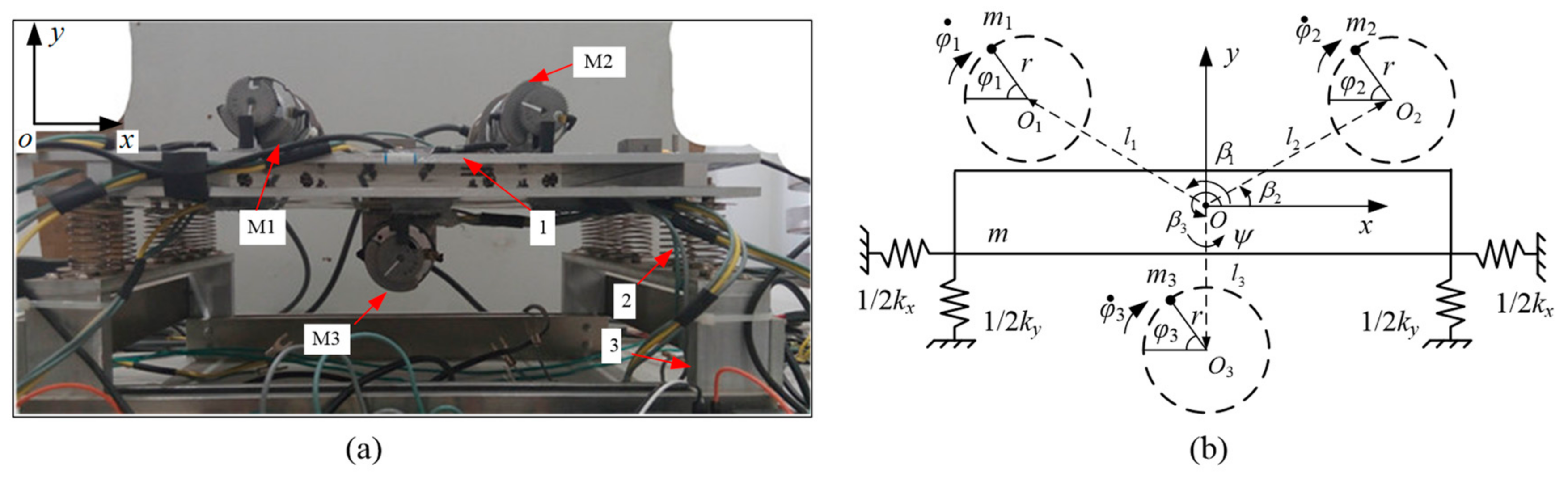
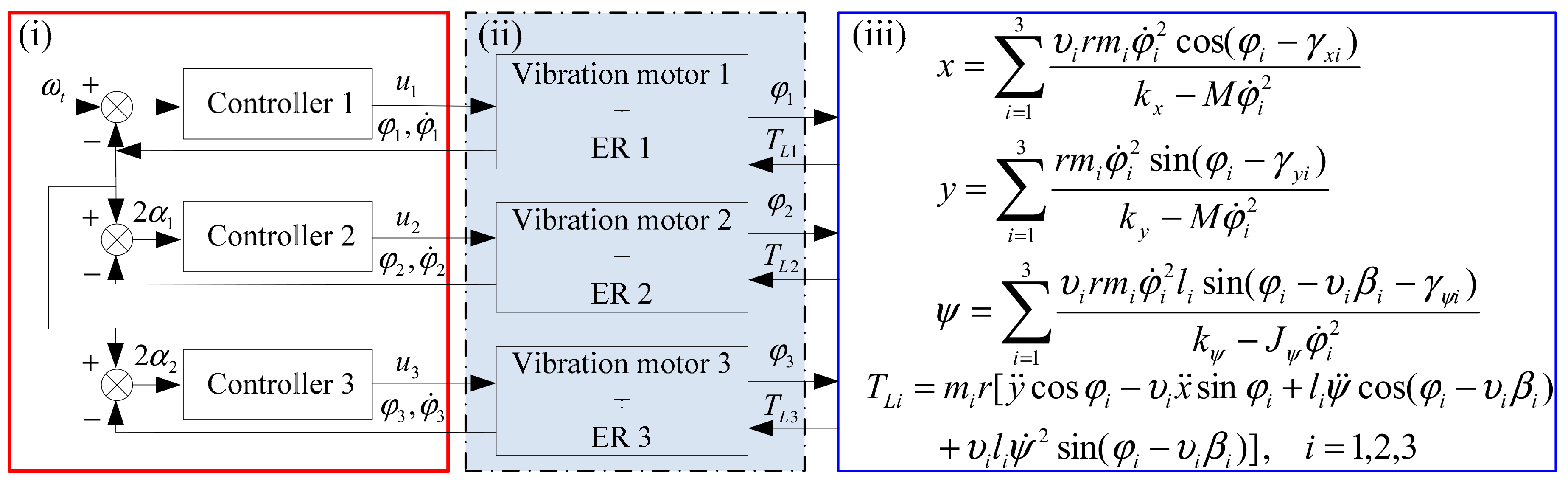
2. Dynamic Model of the Vibration System

Figure 1 shows the experimental vibration machine and its dynamic model. Comparing Figure 1a,b, the dynamic model of the vibration system consists of a rigid body(Num 1), three vibration motors including DC motor and ER(Code M1–3), springs(Num 2), and a fixed base(Num 3). The springs connect the base with the rigid body. Three DC motors drive three ERs in the same rotational direction, respectively. In Figure 1b, o i are the rotational centers of ERs, r is the eccentric radius of three ERs, φ i denote ER rotates about its spin axis, o is the mass center of the vibration system, l i is the distance between the rotational center o i and the center of mass o , β i is the angle between o o i and x -axis, m is the mass of the rigid body, m i are the masses of ERs, k x , k y , k ψ are stiffness of springs, f x , f y , f ψ are damping of springs, and i = 1 , 2 , 3 . The mass center o translations are x and y , and angular rotation is ψ .
To analyze the dynamics of the vibration system driven by three ERs using control synchronization, the coupling characteristic of three ERs in the state of vibration synchronization should be investigated firstly. At present, the average method of the modified small parameter is one of the most systematic methods to study vibration synchronization [10,11,12]. Considering the paper length, we only give the key equations using this method, and the detailed deduced process can be seen in reference [33].
The electromechanical mathematic model of the vibration system is as follows [33]:
M x ¨ + f x x ˙ + k x x = i = 1 3 υ i m i r φ ˙ i 2 cos φ i + φ ¨ i sin φ i ,
M y ¨ + f y y ˙ + k y y = i = 1 3 m i r φ ˙ i 2 sin φ i φ ¨ i cos φ i ,
J ψ ψ ¨ + f ψ ψ ˙ + k ψ ψ = i = 1 3 υ i m i r l i φ ˙ i 2 sin φ i υ i β i φ ¨ i cos φ i υ i β i ,
J i φ ¨ i + f i φ ˙ i = T e i m i r [ y ¨ cos φ i υ i x ¨ sin φ i + l i ψ ¨ cos φ i υ i β i + υ i l i ψ ˙ 2 sin φ i υ i β i ] ,   i = 1 , 2 , 3 ,
where T L i = m i r [ y ¨ cos φ i υ i x ¨ sin φ i + l i ψ ¨ cos φ i υ i β i + υ i l i ψ ˙ 2 sin φ i υ i β i ] , T e i are the electromagnetic torques of three motors, J i m i r 2 are the moment of inertia of ERs, J ψ is the equivalent moment of the vibration system, M = m + m 1 + m 2 + m 3 , f 1 and f 2 are the damping coefficient of the axis of the motor, υ i = 1 denotes the motor rotates clockwise, and ( ¨ ) denotes d 2 ( ) / d t 2 .
The steady-state system responses are obtained as follows [33]:
x = i = 1 3 υ i r m i φ ˙ i 2 cos ( φ i γ x i ) k x M φ ˙ i 2 ,
y = i = 1 3 r m i φ ˙ i 2 sin ( φ i γ y i ) k y M φ ˙ i 2 ,
ψ = i = 1 3 υ i r m i φ ˙ i 2 l i sin ( φ i υ i β i γ ψ i ) k ψ J ψ φ ˙ i 2 ,

3. Control Synchronization

From Equation (1), it can be remarked that the vibration system excited by three ERs is a typical underactuated system, which is also a multiple-input-multiple-output system [15]. The backstepping control is usually selected to design the controller of an underactuated system. However, it is not necessary for the vibration system. Since the object of this underactuated system in this paper is the motion trajectory of the mass center of the vibration system, Equation (1) can be uncoupled from a dynamic perspective. That is, the motion of the mass center of the system depends on the phases of three ERs. If the phase difference is zero, the resultant force acting on the vibration system is maximum, and its driving power is also maximum. To achieve the desired motion of the maximum force and the maximum driving power, the object is converted into controlling the same phase motion (synchronization) of three ERs ( φ 1 = φ 2 = φ 3 ). Due to the ER being driven directly by the motor, the synchronous motion converts to the motion control of three motors.
However, control synchronization of three motors in the vibration system is different from that in the general system [15,16]. Because of the self-adjusting of the vibration system, the phases of three ERs are usually different in the case of asymmetric structural parameters [33,34]. Figure 2 shows the self-adjusting that the motor drives ER to excite the rigid body and the motion of the rigid body affects the load torque of the motor, which is expressed in (ii) and (iii) using φ i and T L i ( i = 1 , 2 , 3 ) .
Based on the above analysis, the complex motion control of the vibration system converts the tracking control of three motors operating in the disturbance of the self-adjusting of the vibration system. Although control synchronization may satisfy the process requirements of the vibration machines, it still increases the manufacturing cost of the system. Considering this engineering application, this paper will make a comparative study on the control schemes of two motors or three motors. Based on this purpose, the master-slave control is selected as the control strategy of this paper. For the general system driven by three motors, velocity is usually the control object. However, the phase of ER is the control object of the vibration system in this paper. Since the phases of ERs are increasing with time and unbounded, the phase difference between ERs is selected as the control object. Hence, the master motor is used only for open-loop and closed-loop velocity control, and the slave motor is used for closed-loop phase tracking control as shown in (i) of Figure 2.
To sum up, Figure 2 shows the electromechanical coupling of the vibration system driven by three ERs. The vibration system using control synchronization can be divided into three parts The key part is (ii) which acts as a bridge between (i) and (iii). The coupling process is that controller outputs voltage u i ( i = 1 , 2 , 3 ) to the motor, the motor drives ER to produce the exciting force, the rigid body is forced to move and affects the velocity and phase of ER, and the controller detects the signal to adjust the output voltages of the motors. Where, 2 α 1 = φ 1 φ 2 and 2 α 2 = φ 2 φ 3 denote the phase difference.
Because the AC motor has a strong mechanical characteristic, it is not easy to observe the change of velocity with the change of load torque. Thus, a DC motor is used as the driving source to study the control synchronization of three ERs. At present, the pulse width modulation (PWM) of voltage is the most common technique of motor control in engineering. Hence, the controller of the DC motor in Figure 2 is divided into two parts, the velocity or phase controller and the PWM calculator as shown in Figure 3.
Although the vibration system has this self-adjusting capability, it is still bounded from the control perspective. In other words, firstly, Equation (2) is the function of variable φ 1 and φ 2 with time, and other symbols of Equation (2) are constant because the system structure parameters are constant. Secondly, because trigonometric functions are bounded, T L i in Equation (1) are also bounded. Therefore, the role function of the self-adjustment of the vibration system can be considered as an internal disturbance as shown in Figure 3.
Considering the electromechanical coupling, the disturbance of the self-adjusting of the vibration system is a fast variable with time according to Figure 2 and Equation (2). Therefore, the method of SMC is more suitable for this kind of control synchronization with internal parameter perturbations and disturbances [28,29].
Defining the velocity of the master motor and the phase difference between motors as the state variables, z 1 = φ ˙ 1 , z 2 = 2 α ˙ 1 and z 3 = 2 α ˙ 2 , the state equations of the master motor and the slave motors are rearranged respectively as follows:
z ˙ 1 = a 1 z 1 + b 1 u 1 + W 1
z ˙ 2 = a 2 z 2 + b 1 u 1 b 2 u 2 + ( a 1 a 2 ) z 1 + W 1 W 2
z ˙ 3 = a 3 z 3 + b 1 u 1 b 3 u 3 + ( a 1 a 3 ) z 1 + W 1 W 3
where a i = f i R i + K t i K e i J i R i , b i = K t i J i R i , W i = Δ a i + Δ b i T L i / J i , i = 1 , 2 , 3 ; a i and b i denote the nominal value of parameters, Δ a i and Δ b i denote the perturbation of parameters, W i denote the lump uncertainties from the self-adjusting of the vibration system, and it is bounded because of T L i are also bounded.
Since there is master-slave control no matter how many motors, it is a combination of two motors. Due to the length of the paper, the detailed design process of controllers can be seen in reference [34].

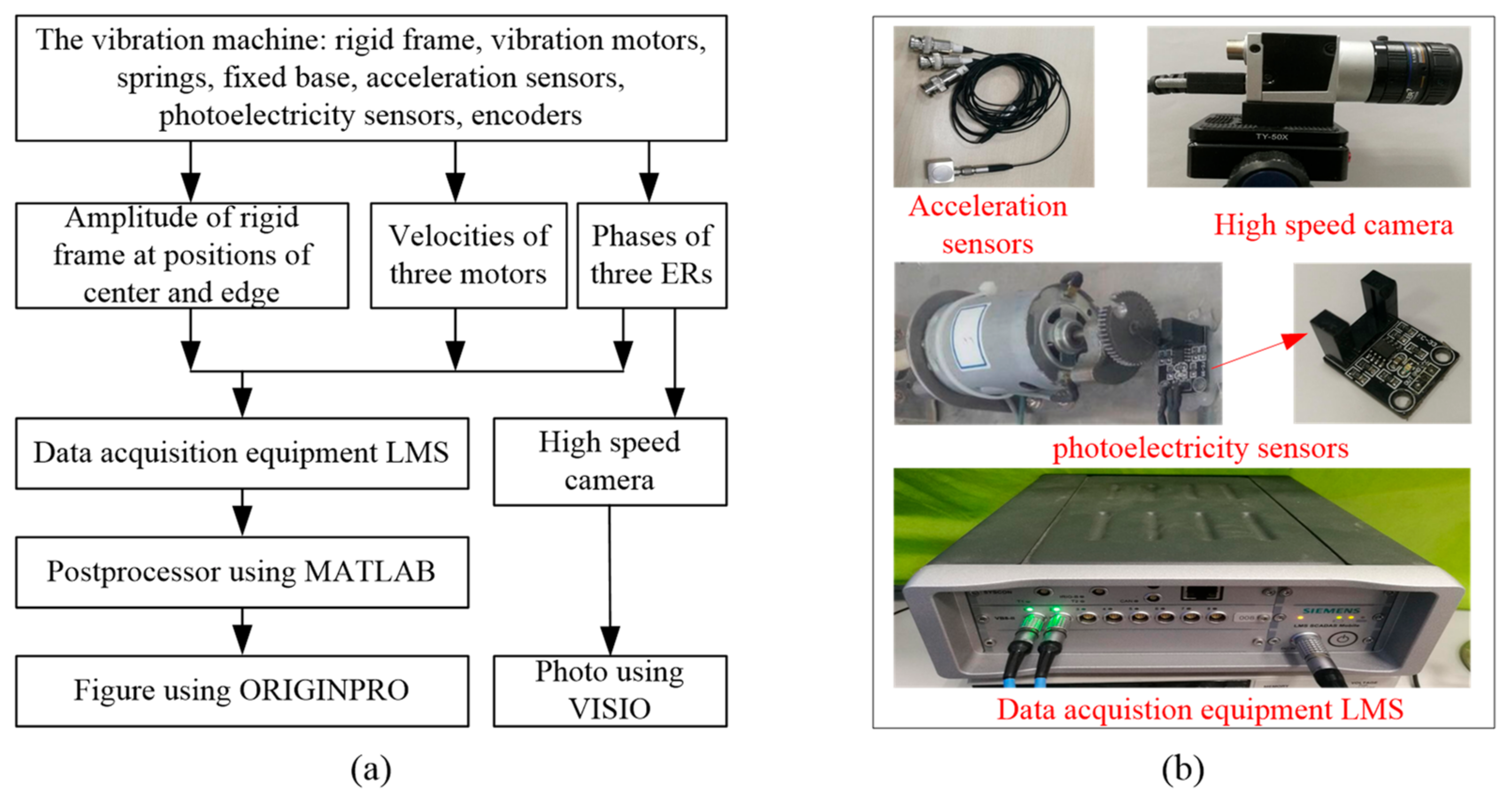
4. Experimental Design of the Control System

The performance of the proposed controller of DSMC is experimentally evaluated using a vibration machine, which consists of mechanical structure, hardware circuit, and software program in Figure 4. Next, all parts are described in Table 1. For example, code M1 in Figure 4 denotes DC vibration motor in Table 1.

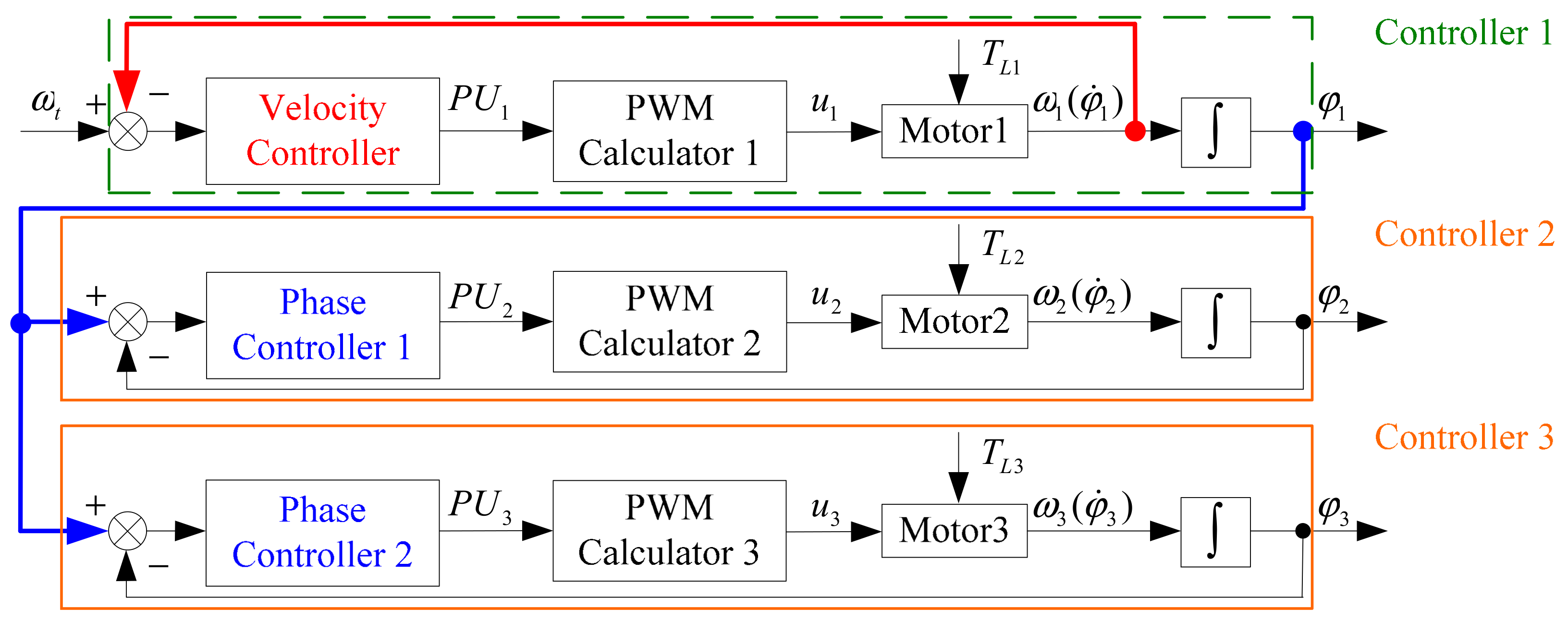
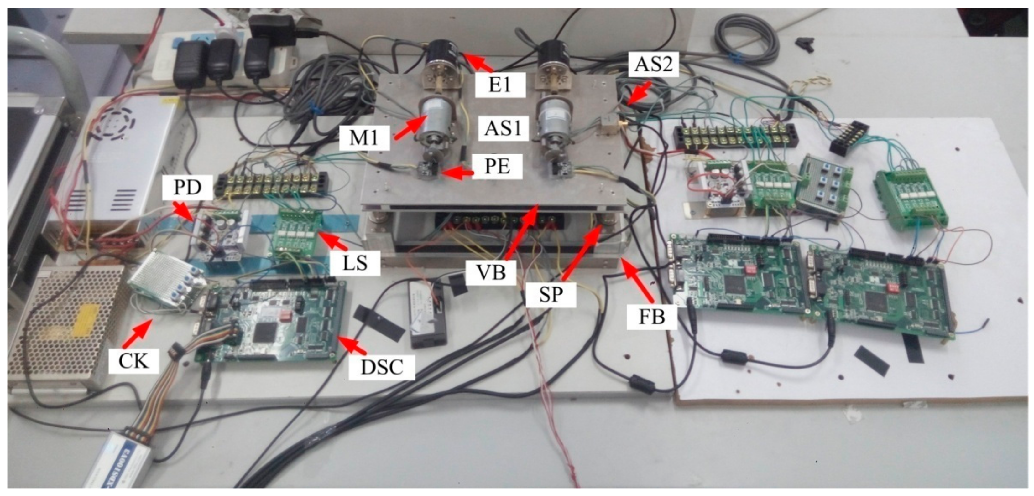
4.1. Hardware Scheme of the Control System

In this Section, some important parts will be introduced to prove the authenticity and repeatability of the experiment in this work.
For the control of multiple motors, a microprocessor must control at least two motors at the same time, and it must have strong real-time data processing capability. Because of the closed-loop control, it must be able to receive signals from both encoders measuring motor velocity. To satisfy the above requirements, the microprocessor TMS320F28335 made by the TI corporation is selected in this work. It has 32 bytes size and clock frequency of 150 MHz, and high-precision PWM output, and floating-point computing capability.
In the vibration machine, the physical unit of the phase is usually expressed as the degree. Therefore, a full rotation of the motor has 360 degrees. Hence, the accuracy of the feedback sensor (such as encoders) must be smaller than one degree. Considering comprehensively the above requirements, the incremental encoder E6B2-CWZ6C made by OMROM is selected, which has 1000 resolution.
This work adopts microprocessor TMS320F28335 to assemble a digital signal control system (DSC), which consists of the power circuit, the driven circuit, the sampling circuit, and so on.

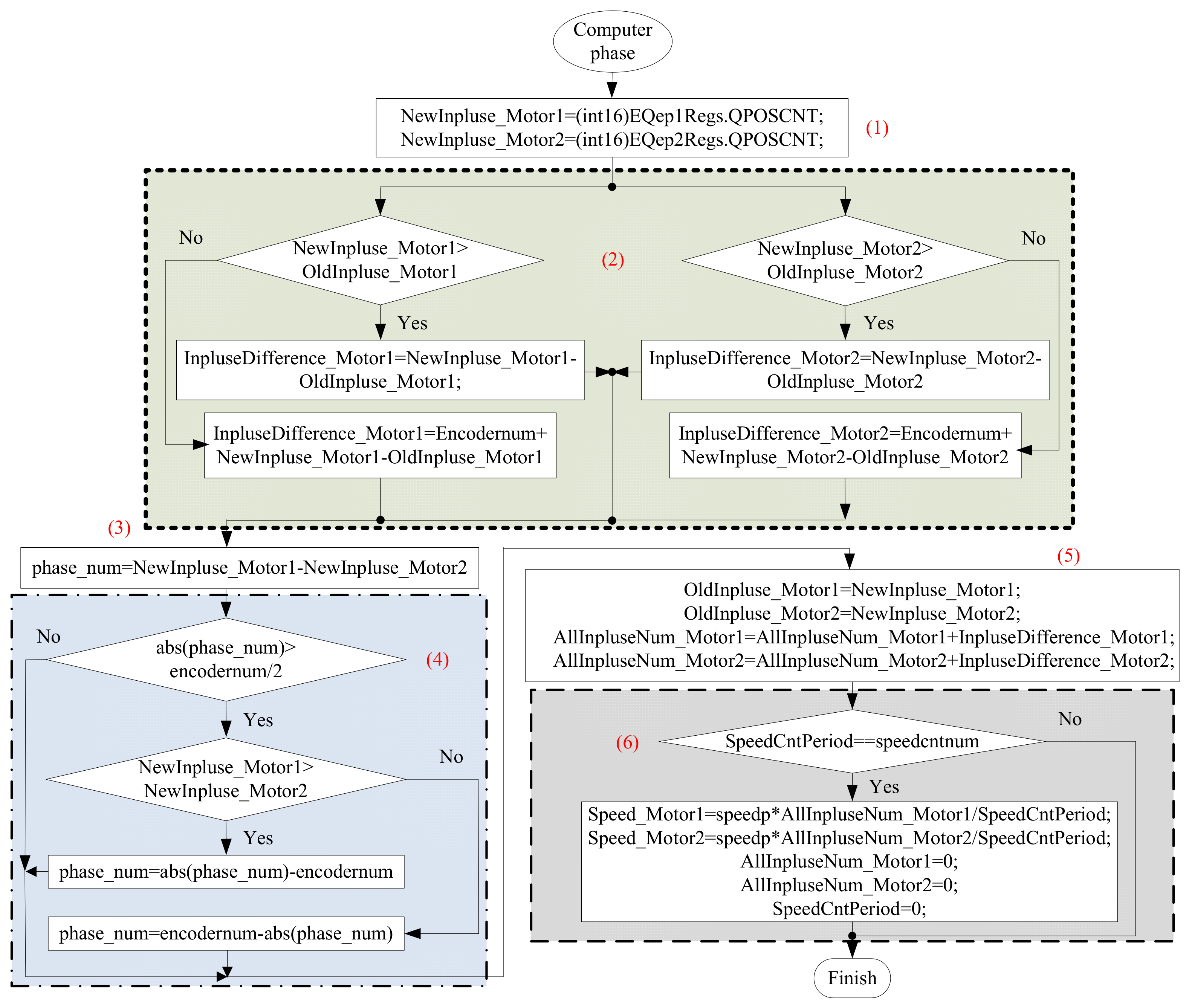
4.2. Algorithm of Velocity and the Phase Difference

A method for calculating the velocity of the master motor and the phase difference between ERs will be presented in this section to match control targets. Because of the vibration performance, the velocity of a vibration motor in one period varies from moment to moment, which causes the difficulty of calculating velocity. The conventional M/T method cannot calculate the exact value of velocity for a vibration motor. For this problem, the approach of measuring multiple rotational periods of the motor is chosen to obtain a more accurate value of velocity. However, too long periods will result in the loss of real-time control. Considering the experimental velocity near 1500 r/min of the motor in this work, the calculating period of the velocity is set at four rotational periods of the motor.
Since the limit of the QEP component of TMS320F28335, the phase difference cannot be calculated directly, which requires a data conversion process. To prevent the accumulation of measuring errors, the Z signal of an encoder is used to clear zero for the calculator function of QEP. Due to the calculator is affected by a clear process, it is not correct to subtract the pulse number of two encoders directly. Next, the data conversion process will be described in detail.
Because there is a master-slave control in this paper, we take two motors as an example to introduce the data conversion process. As shown in Table 2, if the phases of two ERs are either in the 1st and 4th quadrant or in the 2nd and 3rd quadrant, the phase difference between the two ERs is less than π no matter what changes. However, there will be two results when the phases of two ERs are, respectively, in the 1st and 4th quadrant or the 2nd and 3rd quadrant.
After recording the previous and current pulse numbers, it is necessary to determine whether there is a process of clearing zero. As shown in Table 3, the determining algorithm can be formalized through the truth table of the phase difference. To cooperate with Table 3, the sampling period must ensure that more records are carried out in one rotational period of the motor. In other words, the pulse difference between the previous record and the current record must less than the total number of pulses in one rotational period of the motor.
Taking motor 1 as the master motor and motor 2 as the slave one, the calculation flow chart of velocity and the phase difference is shown in Figure 5. Step 1, pulses of two encoders are recorded. NewInpluse_MotorX denotes the value of the encoder in present control period. (int 16)EQepXRegs.QPOSCNT represents the storage unit in hardware system. Step 2, whether there is a clearing process is estimated using Table 2 and Table 3. OldInpluse_MotorX denotes the value of the encoder in previous control period. InpluseDifference_MotorX denotes the phase change of motorX. Step 3, the phase difference is calculated. Phase_num denotes the phase difference between motor 1 and motor 2. Step 4, the phase leading motor is determined. Encodernum denotes the total number of pulses in a full rotation of the motor. Step 5, the values of previous and present pulse numbers are interchanged, and AllInpluseNum_MotorX denotes the total pulses of every encoder are cumulated. Step 6, Speed_MotorX denotes the velocity of the motorX is calculated where speedp means proportionality coefficient and SpeedCntPeriod represents the calculating period of the motor speed. The above six steps are the calculation process of the velocity and the phase for TMS320F28335 processor.

5. Results and Discussion

In this Section, three group experiments of control synchronization are completed based on the master-slave control strategy and DSMC designed in Section 3. All acceleration signals in the vertical and horizontal directions, velocities of motors, and phases of ERs are collected by data acquisition equipment of the LMS corporation, and phases of ERs are recorded by the high-speed camera. The acceleration signals are from the positions of the mass center (code AS1) and the edge of the body (code AS2), as shown in Figure 4. The parameters are shown in Table 4 and Table 5. Figure 6 shows the experimental method in this paper.

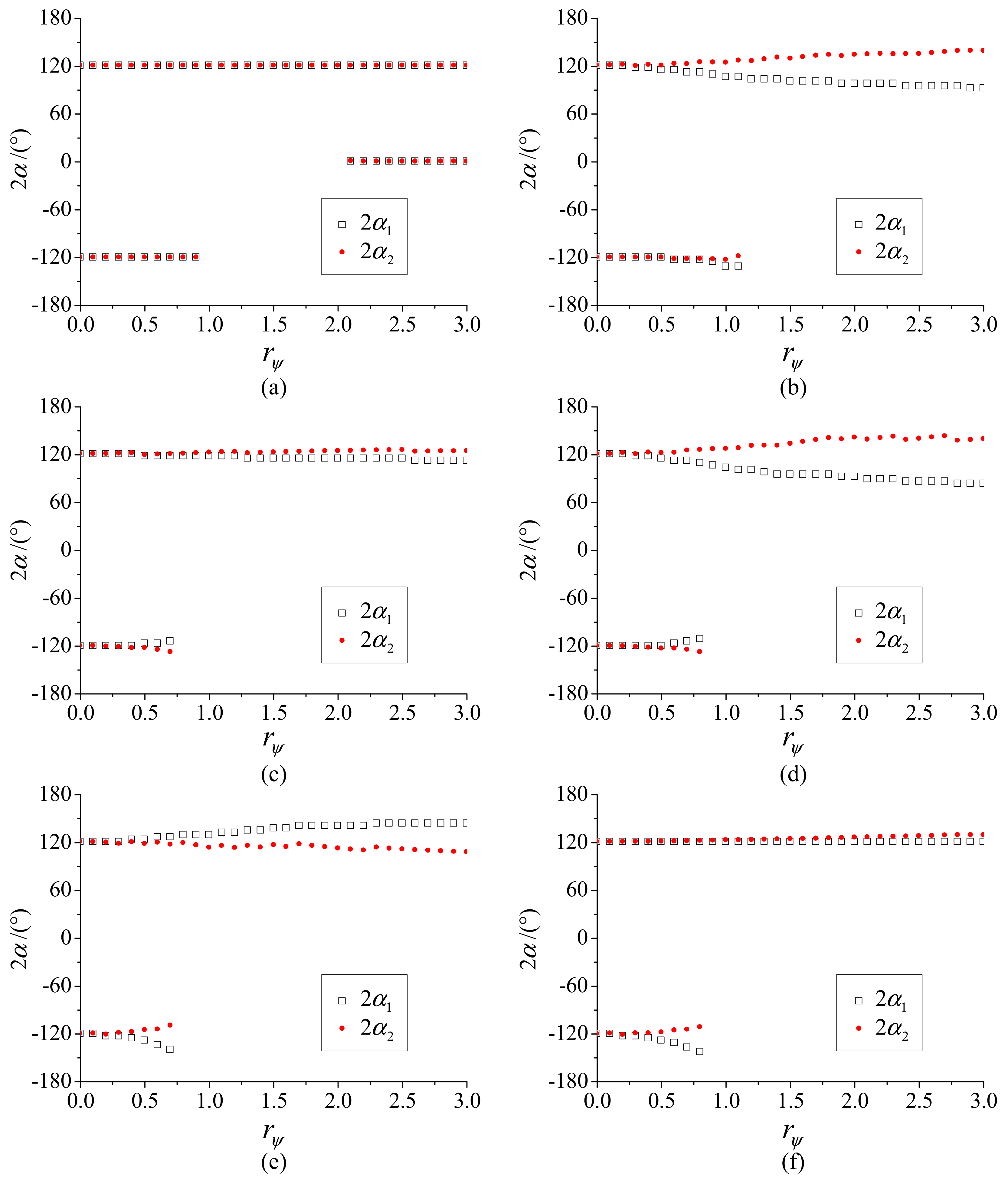
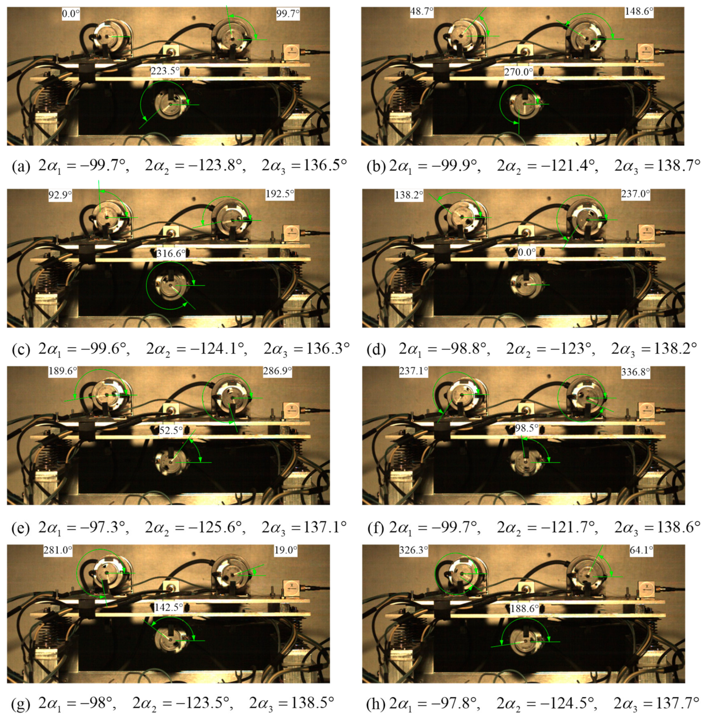
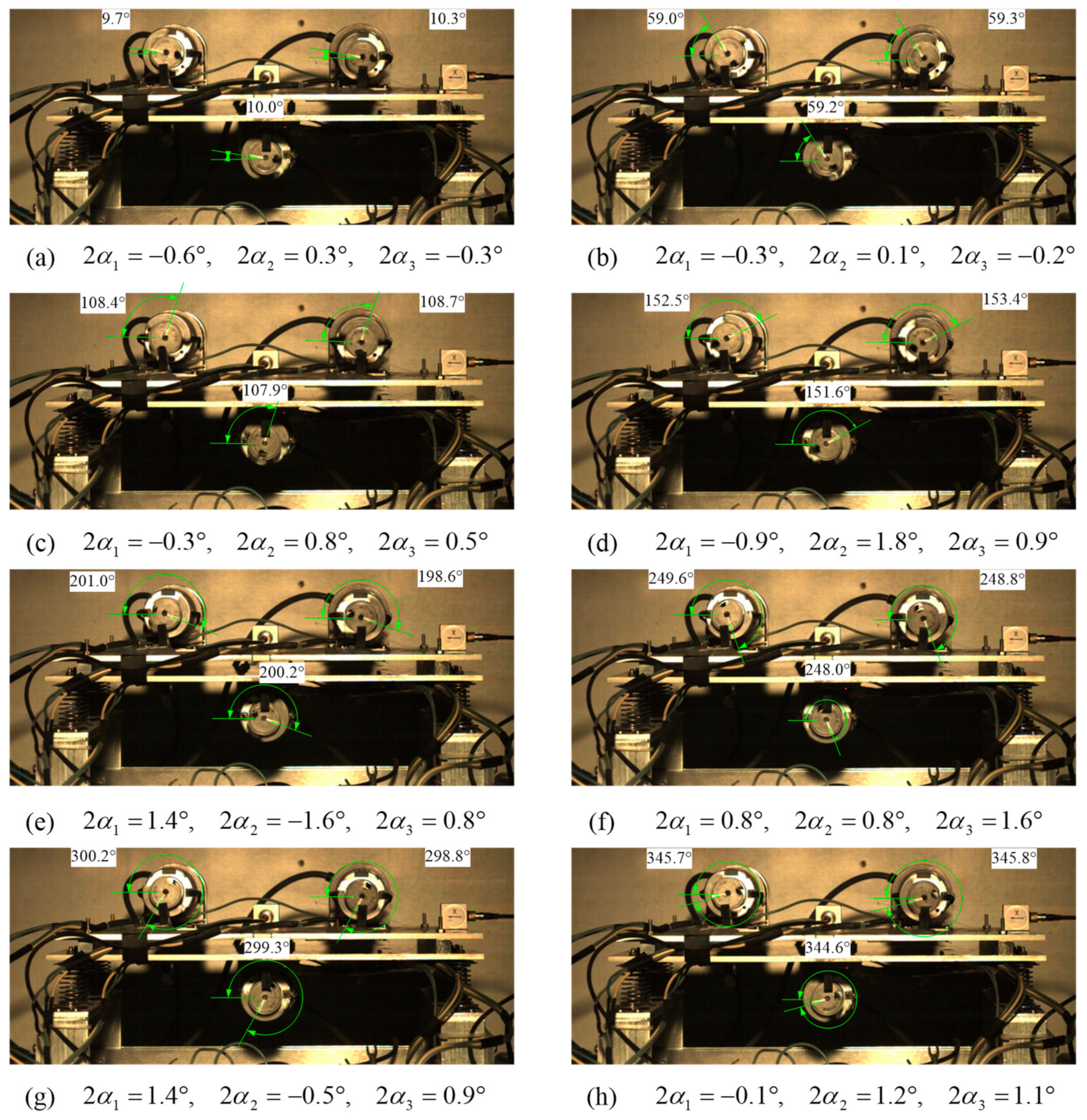
5.1. Vibration Synchronization and Control Synchronization

5.1.1. Numerical Results

Combining the self-adjusting function of the vibration system, the phase difference is the most appropriate parameter for studying synchronization because it represents the different synchronous states. According to references [33,35], we know that the equivalent radius ratio is the key parameter affecting the phase difference. Considering the actual structure of the vibration machine, we choose the equivalent radius ratio r ψ < 5 to investigate the vibration synchronization. Since the motor does the periodic motion, the phase differences of ERs must be periodic change. Therefore, we choose ( 2 π , 2 π ) as the change range of the phase difference. Applying the method provided in Figure 3 in reference [33], we obtain some results as shown in Figure 7.
In general, we make two kinds of comparison including the different fixed distances l i of ER and the different fixed angles β i of ER. Comparing these six group curves, the point r ψ = 2 is the cut-off point of the change of the phase difference. When r ψ < 2 , each phase difference has two stable solutions, which explains that the vibration system driven by three ERs has two synchronous states. By contrast, each phase difference only has one solution except Figure 7a. Figure 7a has two group stable solutions because ERs are symmetrically mounted, which is a limiting case. It can be seen from Figure 7 that the absolution values of these phase differences are close to 120 ° , which explains that the exciting forces of ERs cancel each other out. The phenomenon conforms to the principle of minimum potential energy, which explains why the vibration machine using vibration synchronization does not achieve the increase of the exciting resultant force and driving power. Because the vibration synchronization restricts the application of the three ERs structure, we propose control synchronization to solve this limitation of the vibration system. Therefore, control synchronization is to study how to control the absolution of the phase difference from 120 ° to 0 ° .
Through the above theoretical analysis, we know the change rule of the phase difference as shown in Figure 8. At each moment, three ERs have to rotate close the phase difference of ± 120 ° to keep the center of mass at rest. Although the resultant forces are offset, a torque is created, which causes the body to swing around the center of mass according to Equation (1).
To provide the basis for the master-slave control scheme, we assume two-thirds of ERs have achieved control synchronization to study the change of the phase difference. Figure 9a adopts motor 1 and motor 3 as the control object using control synchronization. Then, since two ERs rotate in the same motion, they can be equivalent to ER 4. At this moment, the three-ERs system becomes a two-ERs system. Similarly, Figure 9b adopts motor 1 and motor 2 as the control object using control synchronization. Comparing with Figure 9a,b is more symmetrical.
When two-thirds of ERs apply control synchronization, the three-ERs system turns into the two-ERs system. Taking Figure 9b as the study example, we give the changes of the phase difference between ER 3 and ER 4 as shown in Figure 10. It can be seen that r ψ = 2 is also the key point. The absolution of each phase difference is close to 180 ° when r ψ < 2 and that is close to 0 ° when r ψ > 2 . In particular, the better the symmetry η = m 3 / m 4 , the closer the absolution phase difference is to the limit value 180 ° or 0 ° .

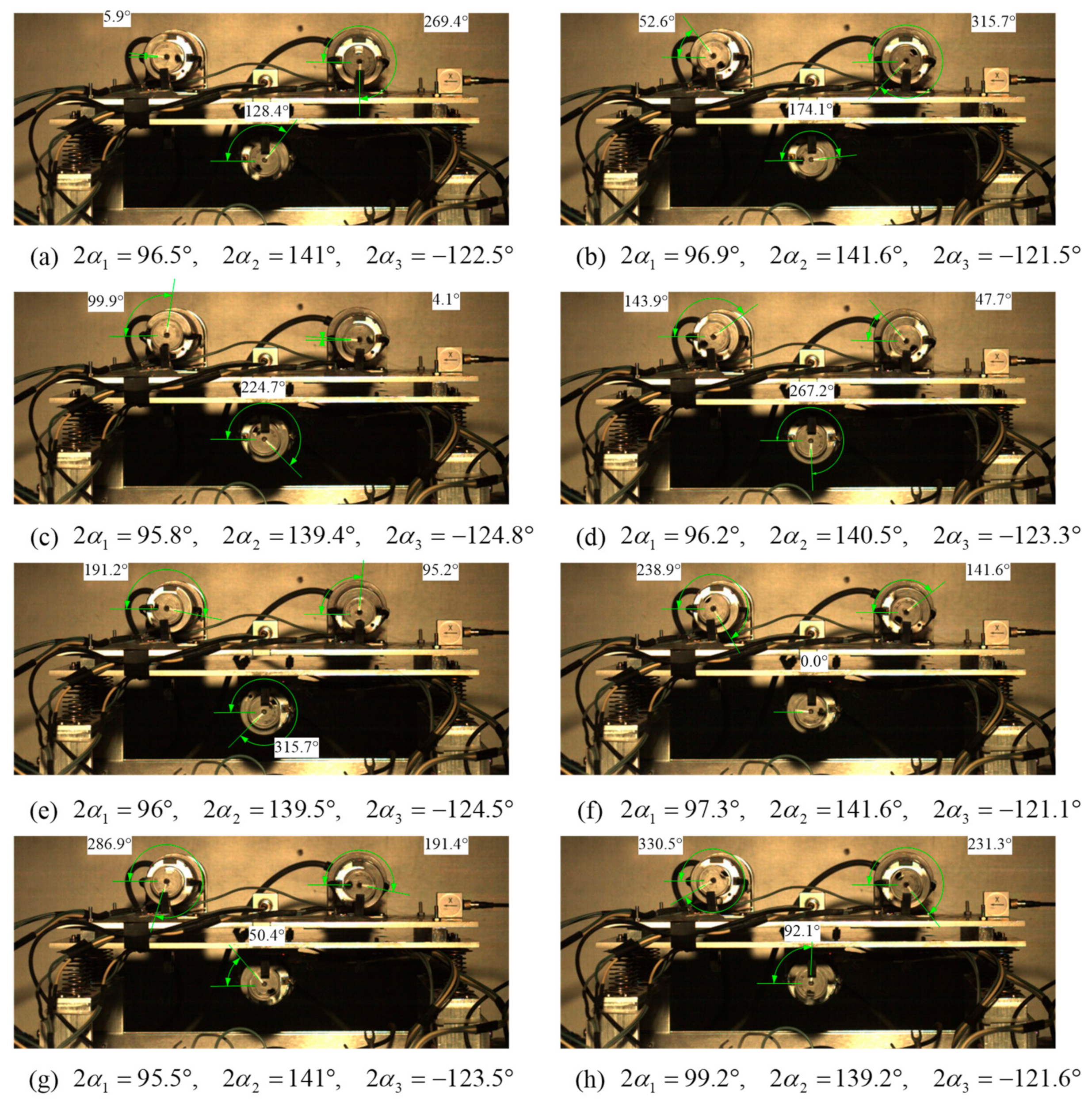
5.1.2. Experimental Results

Figure 11 shows the comparison between vibration synchronization and control synchronization of the vibration system driven by three ERs. Figure 12, Figure 13 and Figure 14 are the high-speed photos for this experiment. The structural parameters are as follows: l 1 = l 2 = 70   mm , β 1 = 155 ° , β 2 = 25 ° , and β 3 = 270 ° . The experimental scheme is that three motors firstly operate without control, and the command of control synchronization is given by the phase controller after 20 s. The control strategy is that the master motor 2 and the slave motor 3 adopt the open-loop control, and the slave motor 1 adopts the closed-loop control. In the last 20 s, slave motor 3 adopts the closed-loop control. To facilitate observation of the motion states of the vibration system from start to steady-state, the data time is delayed for a few seconds during data processing.
The velocities of three motors are shown in Figure 11a. It can be seen from velocity curves that the characteristic of the DC motor rapidly reaches the stable state value after power supply, which is different from that of the AC motor [34]. The synchronous velocity of three motors in the state of vibration synchronization is about 1538r/min. Since motor 1 and motor 2 are controlled by the same DSP, while motor 3 is controlled by another DSP, so the start times are not consistent. Figure 11b shows the phase difference curves of ERs. Because of 2 α 3 = φ 3 φ 1 = 2 π 2 α 1 2 α 2 , we do not give the curve of 2 α 3 in Figure 11b in case there are too many curves in the graph to affect the observation. For the case of the clockwise rotational direction, the phase differences in vibration synchronization are 2 α 1 96 ° and 2 α 2 140 ° , which proves the fact that motor 1 is the leading phase relative to motor 2. According to Figure 7, the change of the phase difference in Figure 11 proves that the theoretical analysis is correct and reasonable.
At about 20 s, motor 2 performs control synchronization and begins to track the phase of motor 1. If three motors operate in the clockwise rotational direction, motor 1 is the leading phase ER affected by the self-adjusting of the vibration system. To hold on the synchronous motion of the zero phase difference, the motion tendency of motor 2 should track motor 1 according to Table 2 and Table 3. As can be seen from Figure 11a, when motor 2 adopts the phase control, the synchronous velocity of three motors rapidly increases to about 1595 r/min and the velocity difference is about 57 r/min. The reason for this phenomenon is that the self-adjusting of the vibration system reduces the load on motor 1 and increases the load on motor 2 to keep the center of mass at rest. Of course, the load torque of the self-adjusting is smaller than the electromagnetic torque of the motor. For the DC motor, the load decreases and the speed increases. Therefore, the synchronous velocity increases after motor 2 using the phase control.
In the second stage, the vibration system seeks a new equilibrium because of the interference of motor 2, which is 2 α 1 0 ° and 2 α 2 167 ° . According to Figure 9 and Figure 10, the change of the phase difference in Figure 11 also proves that the theoretical analysis is correct and reasonable. Due to the accuracy of system modeling and parameter acquisition, although the values are not equal in theory and experiment, the trend is the same, which does not affect the qualitative analysis of the synchronous state. Furthermore, we can find that the self-adjusting reduces the load on the motor of the leading phase and increases the load on the motor of the lagging phase.
In the last 20 s, motor 3 adopts the phase control. Since the phase difference 2 α 2 167 ° in the second stage, the phase of motor 3 is the leading phase relative to motor 1. According to the control principle, motor 3 only needs to wait for motor 1 and motor 2 to track. Therefore, the synchronous velocity is not increased in the third stage. It is important to note that there is the overshoot phenomenon in these three stages, which is caused by the calculation method. We use a fixed time interval to calculate the velocity and the phase difference as shown in Figure 5, which is very susceptible to the collection method. Because of the timeliness and accuracy of the signal feedback, the function of the control method proposed in this paper is limited. By contrast, according to the results of the data, it is proved that the control scheme in this paper is feasible and effective. Furthermore, this set of data demonstrates the feasibility of the control scheme of controlling only the slave motors in the vibration system excited by three ERs. Comparing the overshoot in the second and third stages, it can be seen that the control synchronization is more difficult in the three-ERs system than in the two-ERs system because of the interference of the self-adjusting of the vibration system.
Figure 11c,d are the acceleration amplitudes of the mass center (code AS1 in Figure 4) in both x - and y -directions. Similarly, Figure 11e,f are the acceleration amplitudes of the body edge (code AS2 in Figure 3) in both x - and y -directions. Comparing two measuring positions, the motion state is mainly the swing in the first stage when the vibration system operates in vibration synchronization because y -direction acceleration amplitude of the body edge is greater than that of the mass center. If the vibration system operates in control synchronization, the motion state in the third stage is mainly a circle according to the acceleration amplitude of the mass center. In Figure 11c,d, acceleration amplitudes of the mass center are close equal in the x - and y -directions, and y -direction is about 90° ahead of x -direction, which corresponds to the motion pattern of the clockwise circular motion. Furthermore, the acceleration amplitudes between the mass center and the body edge are close to equal in two directions, and there is not the phase difference between the acceleration amplitude curves of the two positions, which are in accordance with the motion pattern of the rigid body. To sum up, Figure 11c–f show the coupling characteristic that the phase difference affects the motion pattern of the vibration system.
Figure 12 shows the high-speed photos of three ERs with the clockwise rotational directions in vibration synchronization, which is captured by a high-speed camera in 200Hz. The data correctness of Figure 11 is verified according to eight images of the average time. The phase differences are stable near 2 α 1 96 ° , 2 α 2 140 ° , and 2 α 3 124 ° , and are consistent with the data in Figure 11b, which reflect the coupling characteristic of the self-adjusting of the vibration system.
In order to compare Figure 7 and Figure 13 shows the high-speed photos of three ERs with the anticlockwise rotational directions in vibration synchronization. The phase differences are stable near 2 α 1 98 ° , 2 α 2 124 ° , and 2 α 3 138 ° , which reflect another group of solutions when r ψ < 2 .
Using the same way, the high-speed photos of three ERs with the clockwise rotational directions in control synchronization are shown in Figure 14. From eight images of the average time, it can be seen that the phase difference approximately equals zero.
Comparing control synchronization and vibration synchronization by the data in Figure 11, Figure 12, Figure 13 and Figure 14, it can be concluded from these results that the vibration system has achieved the ideal motion trajectory and the max force in the state of control synchronization. Hence, it is a very practical engineering technology applying control synchronization to replace vibration synchronization in the design of the vibration machine driven by three ERs.

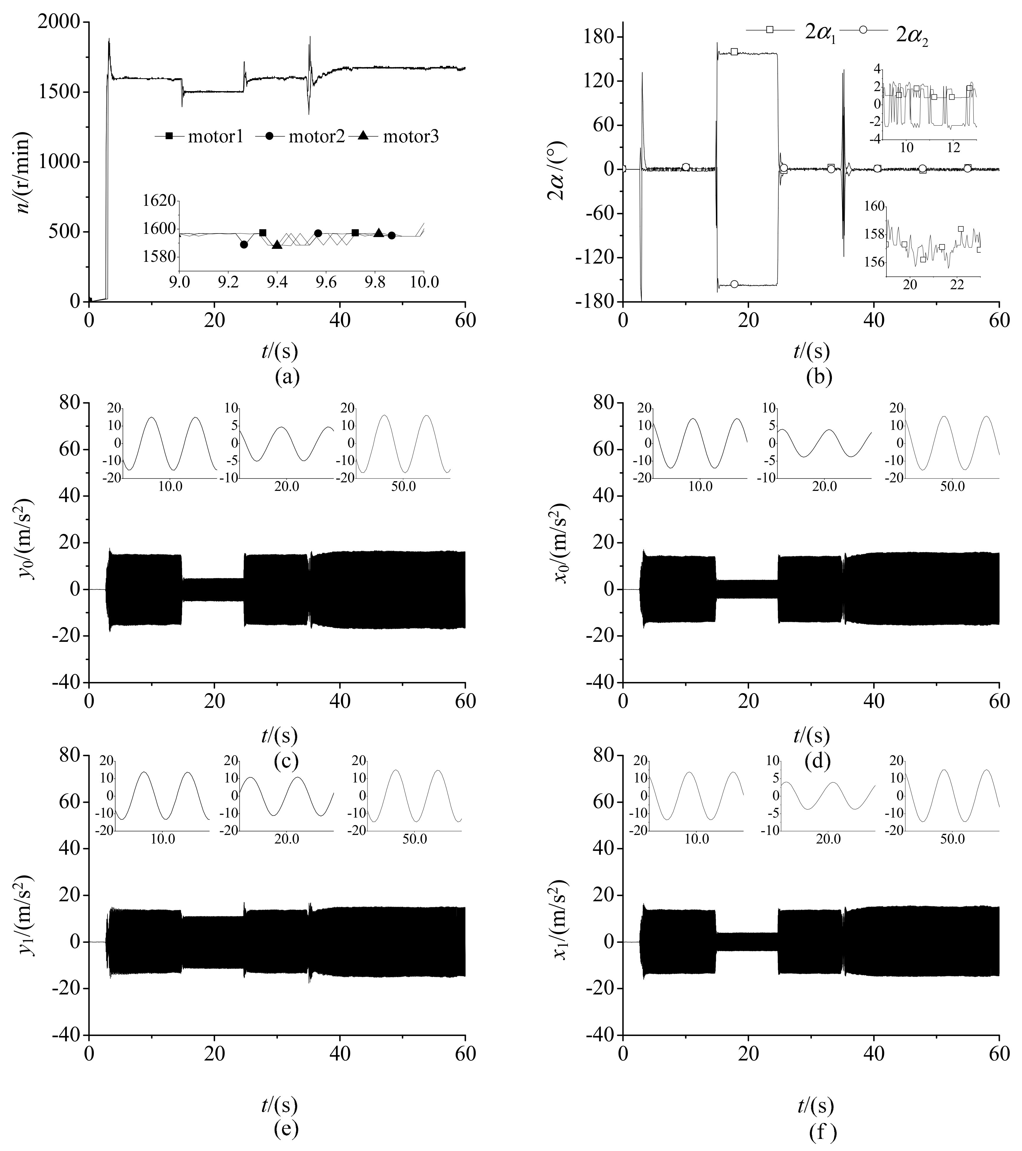
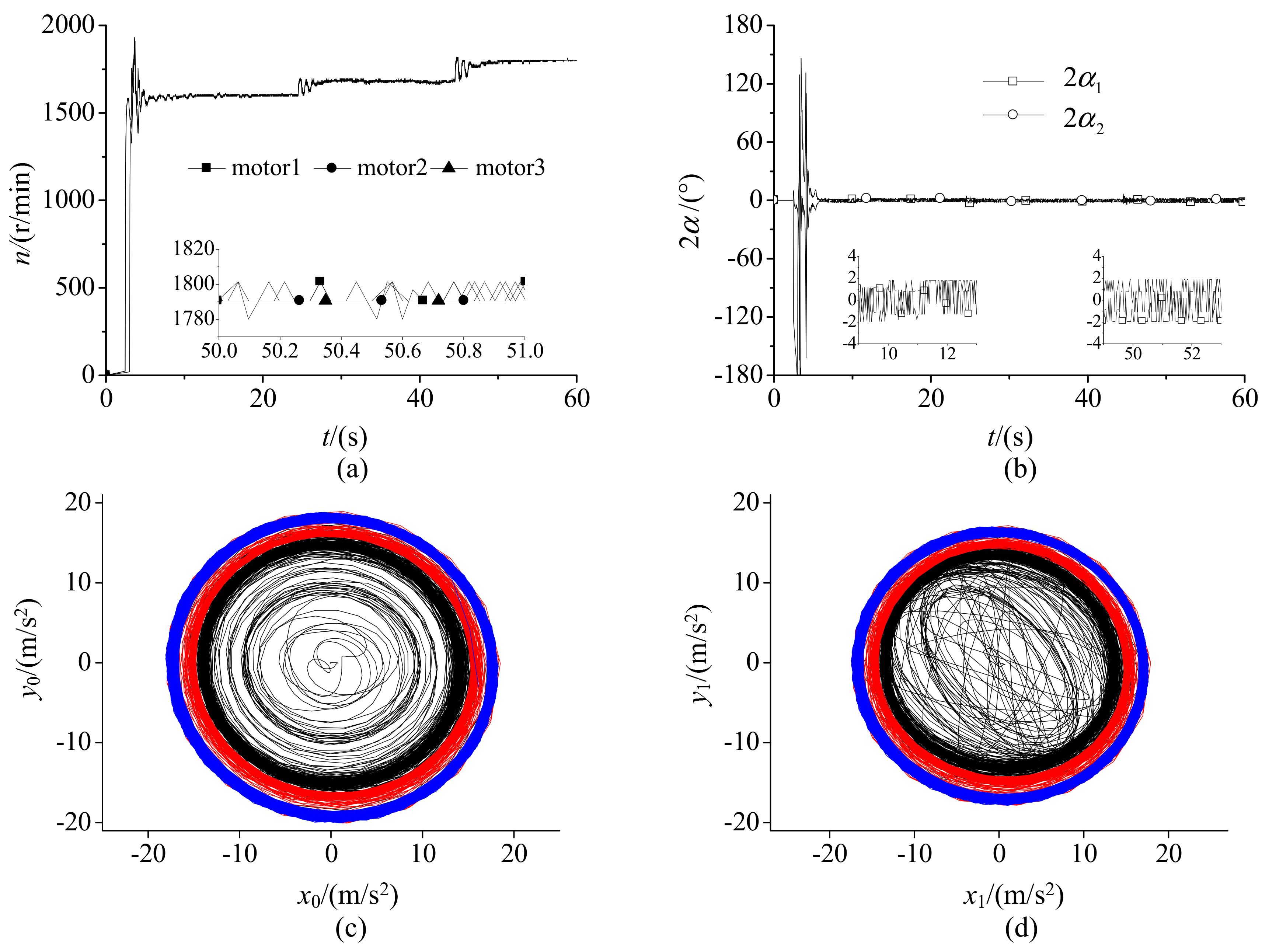
5.2. Control Synchronization of Two Control Schemes

In Figure 11, we adopt motor 3 as the object using the open-loop control and as slave motor using the closed-loop control. Then, Figure 15 selects motor 2 to study the coupling of the vibration system, which is used to further verify the feasibility of control synchronization. The control strategy of the master motor 1 and the slave motors 2 and 3 is selected in this experiment. The experiment is divided into four stages: first, motor 1 chooses the open-loop control and motor 2 and motor 3 choose the closed-loop control. Second, motor 2 chooses the open-loop control and others remain unchanged. Third, motor 2 chooses the closed-loop control again and others remain unchanged. Lastly, motor 1 chooses the closed-loop control of the velocity and others remain unchanged.
Figure 15a shows the velocities of three motors, which is similar to Figure 11a. However, there is a different phenomenon that the velocities of three motors appear over control at the ascending stage. The reason is that due to the master motor adopting the open-loop control, and it being tracked by slave motors, these reduce its load torque result in increasing its velocity, which conforms to the property of the vibration system. In fact, the self-adjustment of the vibration system is effective only when the velocities of motors are close. Therefore, the overshoot phenomenon of the vibration motor after reaching the rated speed is caused by the self-adjustment of the vibration system.
In Figure 15a, motor 2 performs the phase control and begins to track the phase of motor 1. According to the coupling characteristic of the vibration system, motor 2 is the lagging phase ER rotating in the clockwise direction. To achieve the zero phase difference, the motion pattern of motor 2 should increase velocity to track the phase of motor 1. The synchronous velocity of the first stage in Figure 15a equals that of the third stage in Figure 11a. However, the synchronous velocity of the second stage in Figure 15a does not equal that of the second stage in Figure 11a. Since motor 2 is a lagging phase ER, in order to achieve the zero phase difference, motor 2 only has to increase the velocity so that the synchronous velocity of motors will rise. However, motor 3 is a leading phase ER and it only decreases the velocity to wait for motor 1, which causes the synchronous velocity to decrease. Comparing the synchronous velocity in two stages, it has a downward change when motor 2 is not controlled. At this time, the synchronous velocity is about 1500r/min, and it decreases by about 95r/min. In the third stage, the synchronous velocity equals that in the first stage again.
When the vibration system runs into the fourth stage, the master motor adopts the velocity control. Although there are some fluctuations at the beginning of each stage, it does not mean that the controllers are not stable enough, but because of the limit of calculating velocity signal. In Figure 5, it is known from the introduction to the calculating velocity method of vibration motor that obtaining its average velocity requires multiple motor rotational periods to ensure the accuracy of velocity value, which will affect the timeliness of velocity closed-loop control. To verify the effectiveness of the velocity controller, the velocity value is set higher than the synchronous velocity in the first stage, which is set as 1680r/min. As can be seen in the fourth stage, when motor 1 operates with velocity control, the synchronous velocity of the motors rises slowly and finally stabilizes around 1680r/min, and the synchronous velocity increases by about 85r/min.
Figure 15b shows the phase difference curves between motors. The phase difference respectively has fluctuations when the synchronous velocity changes, and the rest time stability near 0° except for the second stage. In a similar way with Figure 10, the phase differences approach ± 180 ° according to Figure 9a and Figure 10. However, the absolution phase difference of the second stage in Figure 15b is smaller than that in Figure 11b. This is because the two-ERs system in Figure 11b is more symmetrical than that in Figure 15b, which conforms to the variation in Figure 9 and Figure 10.
Comparing the acceleration amplitudes of two positions in Figure 15c–f, it can be seen that the vibration system implements the circular trajectory motion. In the first and third stages, the acceleration amplitudes of x - and y -directions of two positions are approximately equal in control synchronization, and the y -direction is 90° ahead of x -direction. However, the acceleration amplitudes of two positions in the fourth stage are greater than those in others, because the synchronous velocity in the fourth stage is greater than those in others.
According to the experimental analysis in Figure 15, the phase controller can be used on different slave motors to achieve the synchronous motion of three ERs with the zero phase difference, which proves the effectiveness of the proposed control scheme. Due to the coupling characteristic of the self-adjusting of the vibration system, the acceleration amplitudes of the vibration system are affected in the cases of vibration synchronization and control synchronization.

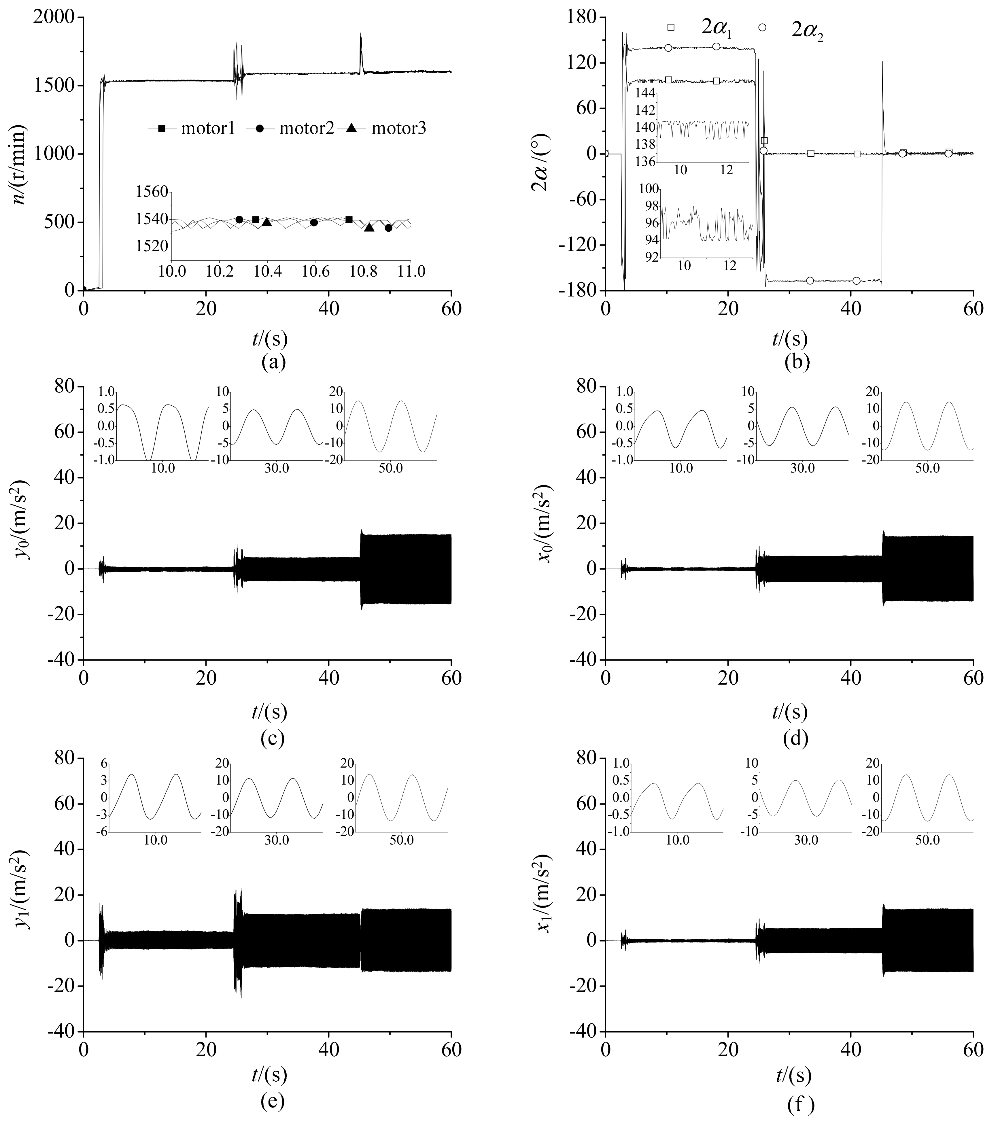
5.3. Control Synchronization of Changing Velocity

Figure 16a shows the velocities of three motors, and Figure 16b shows the phase differences of motors. The velocities of three motors reached the stable state value quickly after the power supply. Because the master motor is controlled at the beginning of the power supply, the velocity controller suffers from the interference of the self-adjusting of the vibration system moment by moment. Comparing the performance between the velocity controller and phase controller in Figure 16, it can be seen that the stability of the controller also depends on the accuracy of feedback data and control period according to the analysis from Section 3. After several seconds, the velocity controller overcomes the interference and begins to adjust the synchronous velocity to the target value. Due to the limit of the calculating velocity period being longer than calculating phase period, the synchronous velocity changes relatively slowly. However, it does not affect engineering applications because it does not take a very long time to stabilize. In the second stage, the fluctuation of velocity is greater than that in the first stage because of the robustness of the phase controller. Once the synchronous motion of the zero phase difference is achieved by the phase controller, the interference of the velocity controller becomes less obvious even if the velocity is changing such as the third stage.
From Figure 16c,d, the motion pattern of two positions is similar to the cases of control synchronization in Figure 11 and Figure 15. Because the synchronous velocity in the first stage is less than that in the second stage, the acceleration amplitudes in the first stage are also less than those in the second stage. In the same way, the acceleration amplitudes in the second stage are also less than those in the third stage.
In this experiment, when two types of controller simultaneously start working, the fluctuations of the data curves of velocity and the phase difference are more obvious than other cases with only controlling slave motors. Because the interference comes from the vibration system itself and its changes are consistent with the input of the controller, the effect of the interference is also obvious at the beginning of each state, which reflects the control complexity of the vibration system.
By analyzing three group experiments, we may conclude that the same phase motion of three ERs in the vibration system can be achieved by control synchronization of two slave motors, but the synchronization velocity is not guaranteed because of the self-adjustment of the vibration system. Only the master motor using velocity control and slave motors using phase control can achieve the ideal synchronous motion of three ERs in the vibration system.

6. Conclusions

This work investigates the coupling characteristic of the vibration system excited by three ERs using the control vibration through theory and experiment, presents a control strategy including control schemes and controllers, and designs a complete control system including hardware and software. The results are as follows:
  • To achieve the ideal motion of the vibration system, the control target of this underactuated system is converted into velocity and phase tracking of three motors from a dynamical perspective. The velocity and phase controllers are designed by employing discrete-time sliding mode control. Considering the dynamic coupling characteristic of the self-adjusting of the vibration system, a method of calculating velocity and the phase difference is proposed to provide data for controllers, which combines experimental conditions.
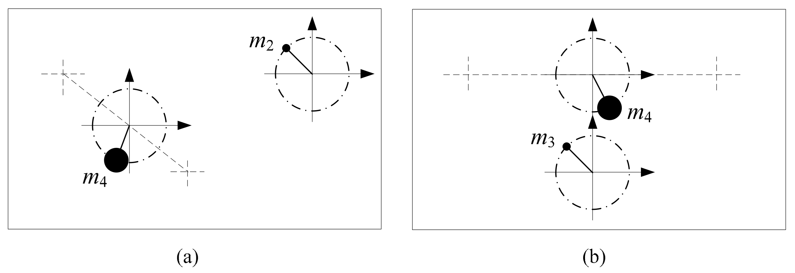
  • The essence of control synchronization is the phase tracking between the master motor and slave motors at the same rotational velocity. According to the synchronous condition and the stability condition, we conclude that the absolution phase differences of three ERs approach 120 ° . when the system runs in the vibration synchronization. Furthermore, when two-thirds of motors adopt the control synchronization, the absolution phase difference between the master motor and the slave motor without control approaches 180 ° .
  • If the master motor is the leading phase ER, the synchronous velocity will rise because of the tracking of other slave motors. By contrast, if the master motor is the lagging phase ERs, the synchronous velocity will drop because the slave motor is waiting for the master motor to track it. Of course, if the master motor adopts the velocity controller, this phenomenon of changing synchronous velocity does not appear.
  • According to the velocity controller and phase controller, the control strategy is divided into two control schemes: controlling only salve motors and controlling all motors. Based on two control schemes, three experiments are achieved to study the dynamic coupling characteristic of the vibration system in control synchronization. The experimental results show that control synchronization is an effective and feasible way to achieve the zero phase difference of three ERs. In addition, the method of control synchronization should be introduced to vibration machines to replace the method of forced synchronization.

Author Contributions

X.C. and L.L. conceived and designed the research. X.C. conducted the theory. J.L. analyzed the data. X.C. wrote the manuscript. L.L. reviewed and edited the manuscript. All authors reviewed the manuscript. All authors have read and agreed to the published version of the manuscript.

Funding

This research was supported by National Natural Science Foundation of China (Grant No. 51905081) and Natural Science Foundation of Hebei Province (Grant No. E2019501117, E2021501014).

Institutional Review Board Statement

Not applicable.

Informed Consent Statement

Not applicable.

Data Availability Statement

Not applicable.

Conflicts of Interest

The authors declare no conflict of interest.

References

  1. Balthazar, J.M.; Felix, J.L.P.; Brasil, R. Short comments on self-synchronization of two non-ideal sources supported by a flexible portal frame structure. J. Vib. Control 2004, 10, 1739–1748. [Google Scholar] [CrossRef]
  2. Blekhman, I.I.; Fradkov, A.L.; Nijmeijer, H.; Pogromsky, A.Y. On self-synchronization and controlled synchronization. Syst. Control Lett. 1997, 31, 299–305. [Google Scholar] [CrossRef] [Green Version]
  3. Djanan, A.A.N.; Nbendjo, B.R.N.; Woafo, P. Self-synchronization of two motors on a rectangular plate and reduction of vibration. J. Vib. Control 2015, 21, 2114–2123. [Google Scholar] [CrossRef]
  4. Koluda, P.; Perlikowski, P.; Czolczynski, K.; Kapitaniak, T. Synchronization configurations of two coupled double pendula. Commun. Nonlinear Sci. 2014, 19, 977–990. [Google Scholar] [CrossRef]
  5. Miklos, A.; Szabo, Z. Simulation and experimental validation of the dynamical model of a dual-rotor vibrotactor. J. Sound Vib. 2015, 334, 98–107. [Google Scholar] [CrossRef] [Green Version]
  6. Sado, D. Nonlinear dynamics of a non-ideal autoparametric system with MR damper. Shock. Vib. 2013, 20, 1065–1072. [Google Scholar] [CrossRef]
  7. Fang, P.; Hou, Y.; Dai, L.; Du, M. Theoretical Study of Synchronous Behavior in a Dual-Pendulum-Rotor System. Shock. Vib. 2018, 2018, 9824631. [Google Scholar] [CrossRef]
  8. Zhao, C.; Zhu, H.; Wang, R.; Wen, B. Synchronization of two non-identical coupled exciters in a non-resonant vibrating system of linear motion. Part I: Theoretical analysis. Shock. Vib. 2009, 16, 505–515. [Google Scholar] [CrossRef]
  9. Blekhman, I.I.; Fradkov, A.L.; Tomchina, O.P.; Bogdanov, D.E. Self-synchronization and controlled synchronization: General definition and example design. Math. Comput. Simul. 2002, 58, 367–384. [Google Scholar] [CrossRef]
  10. Zhao, C.; Zhu, H.; Zhang, Y.; Wen, B. Synchronization of two coupled exciters in a vibrating system of spatial motion. Acta Mech. Sin. 2010, 26, 477–493. [Google Scholar] [CrossRef]
  11. Zhang, X.L.; Zhao, C.Y.; Wen, B.C. Theoretical and experimental study on synchronization of the two homodromy exciters in a non-resonant vibrating system. Shock. Vib. 2013, 20, 327–340. [Google Scholar] [CrossRef]
  12. Chen, X.; Kong, X.; Zhang, X.; Li, L.; Wen, B. On the Synchronization of Two Eccentric Rotors with Common Rotational Axis: Theory and Experiment. Shock. Vib. 2016, 2016, 6973597. [Google Scholar] [CrossRef] [Green Version]
  13. Chen, X.; Kong, X.; Dou, J.; Liu, Y.; Wen, B. Numerical and experimental investigation on self-synchronization of two eccentric rotors in the vibration system. J. Vibroeng. 2016, 18, 744–758. [Google Scholar]
  14. Kong, X.; Chen, X.; Dou, J.; Zhang, X.; Wen, B. Controlled synchronization of two nonidentical homodromy coupling exciters driven by inductor motors in a vibratory system. Proc. Inst. Mech. Eng. Part C J. Mech. Eng. Sci. 2016, 230, 3040–3054. [Google Scholar] [CrossRef]
  15. Chuang, C.-W.; Haung, C.-L.; Lee, C.-D.; Kao, C.-C.; Fung, R.-F. Synchronization and tension control of dual motor systems via MIMO discrete pseudo model following integral variable structure control. Mech Mach. Theory 2009, 44, 499–510. [Google Scholar] [CrossRef]
  16. Sencer, B.; Mori, T.; Shamoto, E. Design and application of a sliding mode controller for accurate motion synchronization of dual servo systems. Control Eng. Pract. 2013, 21, 1519–1530. [Google Scholar] [CrossRef]
  17. Chen, C.-S.; Chen, L.-Y. Robust Cross-Coupling Synchronous Control by Shaping Position Commands in Multiaxes System. IEEE Trans. Ind. Electron. 2012, 59, 4761–4773. [Google Scholar] [CrossRef]
  18. Zhao, D.Z.; Li, C.W.; Ren, J. Speed synchronisation of multiple induction motors with adjacent cross-coupling control. IET Control Theory Appl. 2010, 4, 119–128. [Google Scholar] [CrossRef]
  19. Lin, S.; Cai, Y.; Yang, B.; Zhang, W. Electrical line-shafting control for motor speed synchronisation using sliding mode controller and disturbance observer. IET Control Theory Appl. 2017, 11, 205–212. [Google Scholar] [CrossRef]
  20. Li, L.-B.; Sun, L.-L.; Zhang, S.-Z.; Yang, Q.-Q. Speed tracking and synchronization of multiple motors using ring coupling control and adaptive sliding mode control. ISA Trans. 2015, 58, 635–649. [Google Scholar] [CrossRef]
  21. Balthazar, J.M.; Tusset, A.M.; Brasil, R.M.L.R.F.; Felix, J.L.P.; Rocha, R.T.; Janzen, F.C.; Nabarrete, A.; Oliveira, C. An overview on the appearance of the Sommerfeld effect and saturation phenomenon in non-ideal vibrating systems (NIS) in macro and MEMS scales. Nonlinear Dyn. 2018, 93, 19–40. [Google Scholar] [CrossRef]
  22. Cheng, M.H.; Chen, C.-Y.; Bakhoum, E.G. Synchronization controller synthesis of multi-axis motion system. Int. J. Innov. Comput. Inf. Control 2011, 7, 4395–4410. [Google Scholar]
  23. Mao, Z.; Yuan, J.; Liu, Z. Research on Synchronous Control for Dual-Cylinder System with Unbalanced Loading. In Electrical Information and Mechatronics and Applications, Pts 1 and 2; Applied Mechanics and Materials; Wang, X.D., Xu, B.Y., Zhong, S.B., Eds.; Trans Tech Publications: Stafa-Zurich, Switzerland, 2012; Volume 143–144, pp. 53–57. [Google Scholar]
  24. Tomchina, O.; Kudryavtseva, I. Controlled Synchronization of Unbalanced Rotors with Flexible Shafts in Time-Varying Vibrational Units; IEEE Xplore: St. Petersburg, Russia, 2005; pp. 790–794. [Google Scholar]
  25. Lin, F.-J.; Chou, P.-H.; Chen, C.-S.; Lin, Y.-S. DSP-Based Cross-Coupled Synchronous Control for Dual Linear Motors via Intelligent Complementary Sliding Mode Control. IEEE Trans. Ind. Electron. 2012, 59, 1061–1073. [Google Scholar] [CrossRef]
  26. Jia, L.; Kong, X.; Zhang, J.; Liu, Y.; Wen, B. Multiple-Frequency Controlled Synchronization of Two Homodromy Eccentric Rotors in a Vibratory System. Shock. Vib. 2018, 2018, 4941357. [Google Scholar] [CrossRef]
  27. Fradkov, A.L.; Andrievsky, B.; Evans, R.J. Controlled synchronization under information constraints. Phys. Rev. E 2008, 78, 036210. [Google Scholar] [CrossRef] [Green Version]
  28. Eun, Y.; Kim, J.H.; Kim, K.; Cho, D.I. Discrete-time variable structure controller with a decoupled disturbance compensator and its application to a CNC servomechanism. IEEE Trans. Control Syst. Technol. 1999, 7, 414–423. [Google Scholar] [CrossRef]
  29. Gao, W.B.; Wang, Y.F.; Homaifa, A. Discrete-time variable-structure control-systems. IEEE Trans. Ind. Electron. 1995, 42, 117–122. [Google Scholar] [CrossRef]
  30. Ghabi, J.; Dhouibi, H. Discrete Time Sliding Mode Controller Using a Disturbance Compensator for Nonlinear Uncertain Systems. Int. J. Control Autom. Syst. 2018, 16, 1156–1164. [Google Scholar] [CrossRef]
  31. Liu, Y. Sliding Mode Control for A Class of Uncertain Discrete Switched Systems. Int. J. Control Autom. Syst. 2018, 16, 1716–1723. [Google Scholar] [CrossRef]
  32. Chen, X.; Kong, X.; Liu, Y.; Wen, B. Synchronization and coupling dynamic characteristics of a dual-rotors exciter. J. Vibroeng. 2016, 18, 3318–3328. [Google Scholar] [CrossRef]
  33. Chen, X.; Li, L. Selected synchronous state of the vibration system driven by three homodromy eccentric rotors. J. Low Freq. Noise Vib. Act. Control 2020, 39, 352–367. [Google Scholar] [CrossRef] [Green Version]
  34. Chen, X.; Li, L. Phase Synchronization Control of Two Eccentric Rotors in the Vibration System with Asymmetric Structure Using Discrete-Time Sliding Mode Control. Shock. Vib. 2019, 2019, 7481746. [Google Scholar] [CrossRef]
  35. Zhang, X.; Wen, B.; Zhao, C. Experimental investigation on synchronization of three co-rotating non-identical coupled exciters driven by three motors. J. Sound Vib. 2014, 333, 2898–2908. [Google Scholar] [CrossRef]
Figure 1. The vibration machine is excited by three eccentric rotors (ERs): (a) the vibration machine; (b) the dynamic model.
Applsci 11 07691 g001
Figure 2. Electromechanical coupling of the vibration system driven by three ERs.
Applsci 11 07691 g002
Figure 3. Control synchronization scheme of three ERs.
Applsci 11 07691 g003
Figure 4. Control schematic diagram of the hardware circuit.
Applsci 11 07691 g004
Figure 5. Calculating flow chart of the velocity and the phase difference.
Applsci 11 07691 g005
Figure 6. The experimental method: (a) the experimental flow; (b) the experimental equipment.
Applsci 11 07691 g006
Figure 7. Stable phase differences of three ERs, l 1 = l 2 , β 3 = 270 ° : (a) l 1 = l 3 , β 1 = 30 ° , β 2 = 150 ° ; (b) l 1 = 2 l 3 , β 1 = 30 ° , β 2 = 150 ° ; (c) l 1 = l 3 , β 1 = 25 ° , β 2 = 155 ° ; (d) l 1 = 2 l 3 , β 1 = 25 ° , β 2 = 155 ° ; (e) l 1 = l 3 , β 1 = 45 ° , β 2 = 135 ° ; (f) l 1 = 2 l 3 , β 1 = 45 ° , β 2 = 135 ° .
Applsci 11 07691 g007
Figure 8. Motion state of three ERs using vibration synchronization: (a) one moment; (b) another moment.
Applsci 11 07691 g008
Figure 9. Motion state of two-thirds of ERs using control synchronization: (a) controlling motor 1 and 3; (b) controlling motor 1 and 2.
Applsci 11 07691 g009
Figure 10. Stable phase differences of two-thirds of ERs using control synchronization.
Applsci 11 07691 g010
Figure 11. Comparing vibration synchronization and control synchronization: (a) the velocities of three motors; (b) the phase differences; (c) acceleration amplitude of the mass center in y-direction; (d) acceleration amplitude of the mass center in x-direction; (e) acceleration amplitude of the edge position in y-direction; (f) acceleration amplitude of the edge position in x-direction.
Applsci 11 07691 g011
Figure 12. The phase difference of vibration synchronization of three ERs in the clockwise rotational direction. (ah) are photos of continuous time intervals of 200 Hz.
Applsci 11 07691 g012
Figure 13. The phase difference of vibration synchronization of three ERs in the anticlockwise rotational direction. (ah) are photos of continuous time intervals of 200 Hz.
Applsci 11 07691 g013
Figure 14. The phase difference of control synchronization of three ERs in the clockwise rotational direction. (ah) are photos of continuous time intervals of 200 Hz.
Applsci 11 07691 g014
Figure 15. Comparing different slave motor in control synchronization: (a) the velocities of three motors; (b) the phase differences; (c) acceleration amplitude of the mass center in y-direction; (d) acceleration amplitude of the mass center in x-direction; (e) acceleration amplitude of the edge position in y-direction; (f) acceleration amplitude of the edge position in x-direction.
Applsci 11 07691 g015
Figure 16. Comparing with the different velocities of the master motor: (a) the velocities of three motors; (b) the phase differences; (c) Mass center trajectory; (d) Edge position trajectory.
Applsci 11 07691 g016
Table 1. Code table.
CodeDesignationApplication
DSCControl platformVelocity and phase control of motor
PDPower-driven circuitSupplying power for direct current motor
LSSignal processing circuitProcessing signal of the encoder
CKKeyboardReceiving order
PEPhotoelectric sensorMeasuring motor speed and the phase difference
E1Encoder Providing motor phase signal to control board
AS1Acceleration sensor(accelerometer)Measuring the acceleration amplitude of the body
M1DC vibration motorDriven ER
VBVibration frameFixed motor
SPSpring Connecting vibration frame and fixed base
FBFixed baseSupporting vibration frame and spring
Table 2. Change domain of the phase difference.
CaseER 2 in 1st and 4th QuadrantsER 2 in 2nd and 3rd Quadrants
ER 1 in 1st and 4th quadrantsPhase difference < πa. Phase difference > π
b. Phase difference < π
ER 1 in 2nd and 3rd quadrantsa. Phase difference > πPhase difference < π
b. Phase difference < π
Table 3. The actual value of the phase difference.
CaseReading of 1st with ResetReading of 1st without Reset
Reading of 2nd with resetInexistenceNeeding to complement
Reading of 2nd without resetNormal subtractionNormal subtraction
Table 4. Parameters of the vibration motor.
Motor ParameterUnitValue
Rated velocity: nrpm3000
Armature resistance: R Ω 5.5
Torque constant: KtNm/A25.4
Magnet constant: KeVs/rad1.7
Voltage: uV12
Table 5. The parameters of the vibration system.
ParametersUnitValue
Mass of vibration frame: mg640
Mass of ER: m0g23
Moment of inertia of system: J ψ gm272
Mass of encoder: meg133
Eccentric radius: rmm10
Stiffness of springs in x-direction: kxkyN/m6000
Stiffness of springs in ψ -direction: k ψ Nm/rad1140
Damping of springs in x-direction: fxfyN/(m/s)34
Damping of springs in ψ -direction: f ψ Nm/(rad/s)27
Damping of rotors: f 1 = f 2 = f 3 Nm/(rad/s)0.01
Publisher’s Note: MDPI stays neutral with regard to jurisdictional claims in published maps and institutional affiliations.

