1. Introduction
Minimizing time-dependent characteristics such as volume changes in concrete mixtures is a primary factor in the determination of the performance of concrete elements. Numerous types of fiber are commercially available to manage volume changes that induce cracking in concrete mixtures. The inclusion of fiber can successfully enhance the mixture’s crack control capacity, thereby reducing crack widths and lengths. In addition, steel fiber-reinforced concrete (SFRC) has excellent mechanical characteristics in terms of shear and flexural strength, impact resistance, and fatigue resistance. Additionally, local cracks in SFRC can be controlled by redistributing the cracks throughout the concrete matrix. Recently, SFRC has been implemented for various construction uses, including slabs on ground and structural members [
1].
The literature reports that the mechanical properties of steel fiber-reinforced concrete (SFRC) are influenced by the fiber’s shape, aspect ratio, strength, and inclusion amount. The compressive strength of SFRC is similar to that of plain concrete in that the tensile strength, flexural strength, and toughness is affected directly by the shape of the steel fiber, aspect ratio, and inclusion amount [
2]. Current provisions, i.e., American Concrete Institute (ACI) 360R-06 [
3] and American National Standards Institute/Steel Deck Institute (ANSI/SDI) C-2017 [
4], suggest that the minimum allowable steel fiber content of 14.8 kg/m
3 should be used to control the drying shrinkage and cracking of concrete deck slabs.
Literature [
5] indicated that drying shrinkage in SFRC can be reduced with an increase in the inclusion amount of the steel fiber and that the dry shrinkage strain in SFRC is about 39.9% to 57.6% less than in plain concrete. Similarly, free-drying shrinkage tests of SFRC using the aspect ratio and mix ratio of hooked-end steel fiber as variables and found that the free-drying shrinkage strain of SFRC is about 50% to 60% less than that of plain concrete [
6]. Further, concrete reinforced with steel fiber delays the cracking point and decreases the maximum and average crack widths compared to plain concrete [
7]. The free-drying shrinkage of SFRC according to type of steel fiber and also found that hooked-end steel fiber is the most effective type [
7]. Hooked-end steel fiber not only has been shown in previous studies to improve mechanical properties, but it also provides excellent control of drying shrinkage. Also, hooked-end steel fiber can easily be pulled out of concrete due to its low bond strength [
8].
In this study, we employed newly developed arched steel fiber to enhance the bond strength between concrete and steel fiber and evaluated the drying shrinkage of SFRC that contained arched steel fiber. We then compared our test results to various predictive model results for the drying shrinkage of SFRC.
2. Experimental Program
2.1. Materials and Specimen Preparation
When using SFRC with arched fiber, concrete cracking is inhibited and ductility is increased when the concrete structure is subjected to bending or tensile force.
Table 1 shows the specifications of the arched steel fiber used in this study.
Table 2 shows the concrete mix proportions of the ordinary Portland cement (OPC), fine aggregate (washed sea sand), and coarse aggregate (crushed stone) used in this study. Because the addition of steel fiber reduces the slump and makes it difficult to secure proper workability, we added a powder-type, high-performance, water-reducing agent (WRA) to the mix at 0.8% WRA compared to the cement mass.
2.2. Free-Drying Shrinkage Tests
We conducted free- and restrained-drying shrinkage tests to evaluate the drying shrinkage characteristics of concrete reinforced with arched steel fiber. The minimum steel fiber contents (14.8 kg/m
3 and 20 kg/m
3) suggested in ACI 360R-06 [
3] and ANSI/SDI C-2017 [
4], respectively, to control the drying shrinkage and cracking of concrete were set as variables.
Table 3 presents the variables used in the drying shrinkage tests.
We conducted the free-drying shrinkage tests in accordance with KS F 2424 [
9] and KS F 2595 [
10]. We prepared the specimens using a 100 × 100 × 400 mm beam mold suggested in KS F 2424 [
9] and fabricated two specimens for each variable (each steel fiber content). We installed a dial gauge at the top of each specimen after demolding and measured the free-drying shrinkage strain once a day. The specimens were set up in a chamber that had a constant temperature and humidity. The measurements were taken for 56 days of aging from the day the concrete was poured.
2.3. Restrained Drying Shrinkage Tests
We conducted the restrained drying shrinkage tests in accordance with KS F 2595 [
10]. These tests are known to be favorable for evaluating the restrained drying shrinkage characteristics of members with straight-line geometry, such as slab members. Plain concrete and concrete reinforced with an arched steel fiber content of 14.8 kg/m
3 (SFRC14.8) were set as variables based on the fiber content. We prepared the specimens using a dumbbell-shaped mold to the size suggested in KS F 2595 [
10] and fabricated three samples for each variable (plain and SFRC).
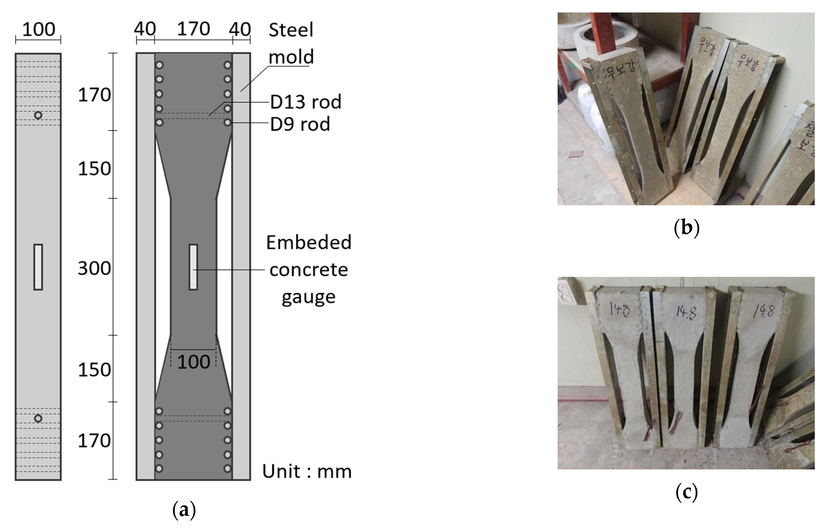
Figure 1a shows the size of the specimen and it was restrained with a rebar of D13 at the ends. We embedded a gauge in the center of each specimen to measure the restrained drying shrinkage strain. By connecting the embedded gauge to a data logger, we could measure the strain once per hour. The measurements were taken for 56 days from the day the concrete was poured.
Figure 1b shows plain concrete specimens, and
Figure 1c shows SFRC14.8 specimens used in the restrained drying shrinkage tests.
2.4. Drying Shrinkage Tests for Deck Slabs
We conducted drying shrinkage tests of deck slabs by reinforcing a scaled-down deck slab with arched steel fiber instead of wire mesh to examine the arched fiber’s mitigating effects on drying shrinkage for deck slabs that may be used in the field. The variables for the scaled-down deck slab specimens are a deck slab reinforced with wire mesh that corresponds to 0.2% of the concrete volume and a deck slab reinforced with arched steel fiber that corresponds to 0.25% of the concrete volume.
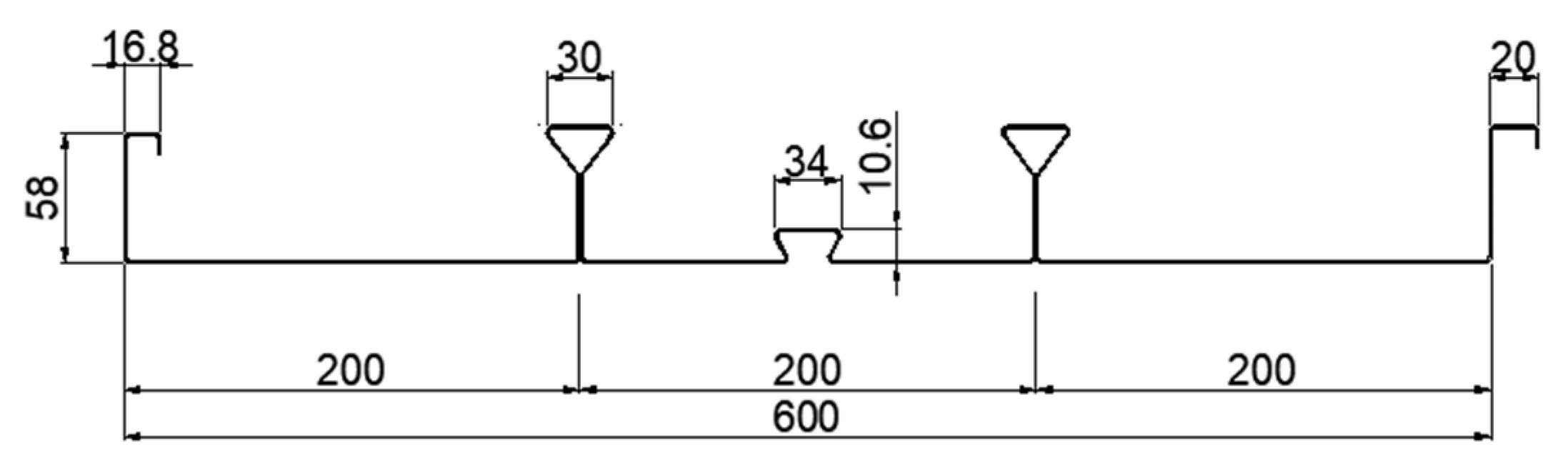
Figure 2 and
Table 4 present a cross-section and the mechanical properties of the deck plates (used as slab molds), respectively. Because the deck plates used in this study served as tensile reinforcement, we installed only wire mesh to control drying and plastic shrinkage at the top of the deck plate without installing tensile reinforcement at the bottom of the deck plate.
Figure 3 and
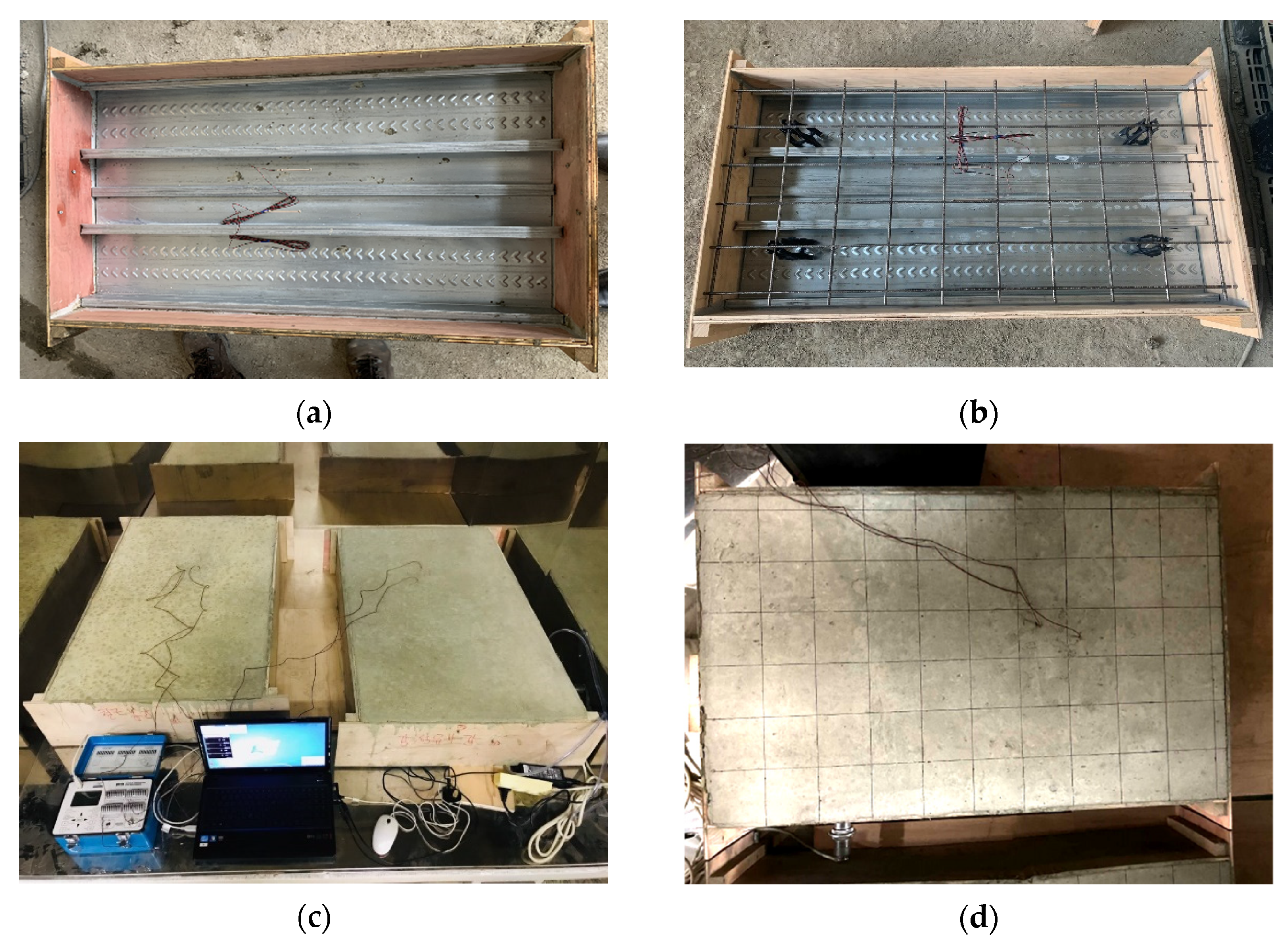
Figure 4 show the fabricated slab specimens.
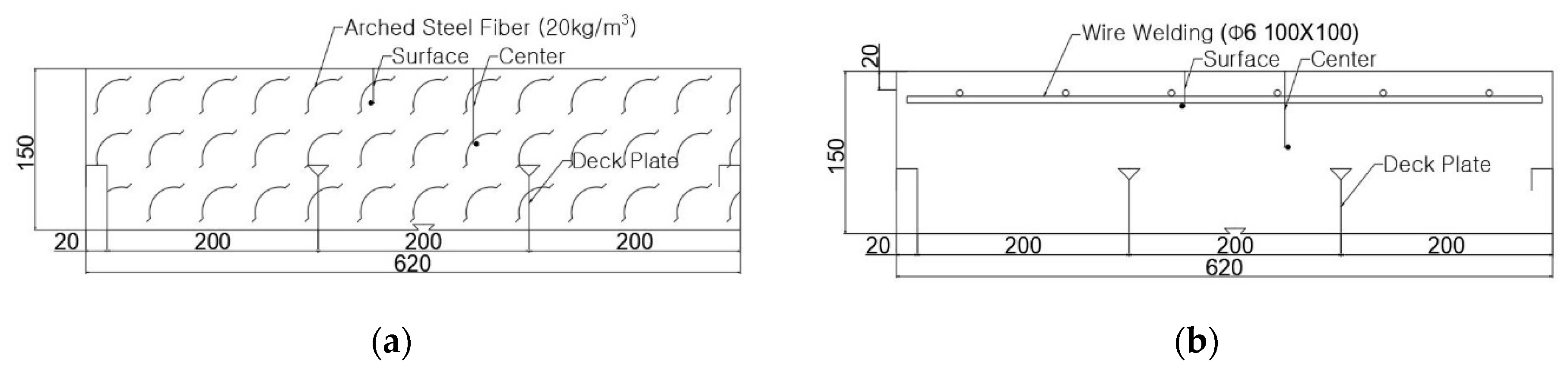
Figure 3a shows the 620 × 1020 × 150 mm formwork, and
Figure 3b shows the deck plate installed at the bottom of the formwork. We then embedded gauges 30 and 70 mm from the top to measure the drying shrinkage strain at the surface and at the center of the deck slab.
Figure 4a shows the fishing lines (which were removed after the concrete was poured) that were used to affix the embedded gauges.
Figure 4b presents the case of the deck slab reinforced with wire mesh (Φ6 100 × 100 mm) that was installed at the top of the slab prior to concrete pouring using spacers.
Figure 4c,d shows the pouring and curing of the concrete, respectively. We exercised caution when pouring the concrete so as not to move or damage the embedded gauges. Dry-curing took place after we covered the poured concrete with vinyl.
For the scaled-down deck slab drying shrinkage tests, we placed the specimens in a chamber with constant temperature and humidity after 24 h of curing. We maintained the ambient temperature at 24 ± 2 °C and humidity at 40 ± 5%, which were the same conditions used for the free-drying shrinkage tests. In addition, we conducted these tests without removing the formwork to generate drying shrinkage on the deck slab surface. To measure the drying shrinkage strain at the surface and at the center of each specimen, we connected the strain gauges to a data logger to record the changes in strain. We measured the crack geometry and width on the surface every seven days.
3. Experimental Results
3.1. Free-Drying Shrinkage Test Results
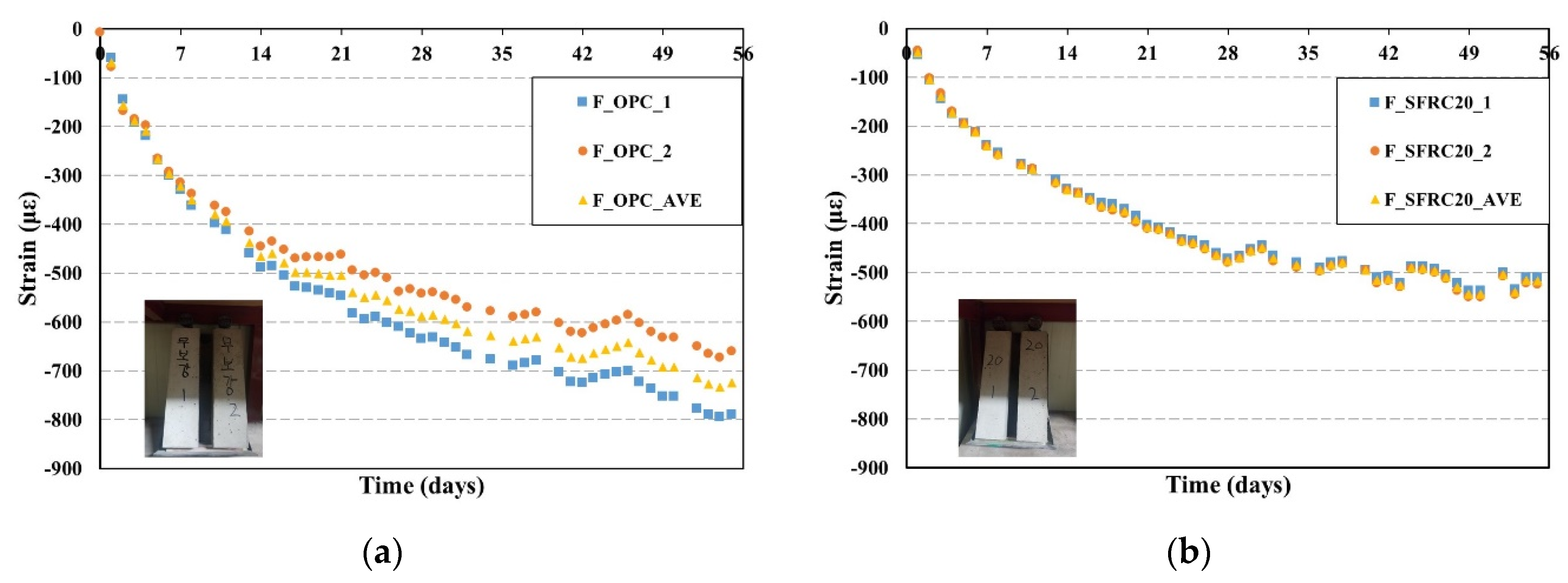
Figure 5 shows the measured free-drying shrinkage strain in terms of aging (days).
Figure 5a shows the results for the case of the plain concrete. After 56 days of aging, the free-drying shrinkage strain ranged from 620 to 790 με, with slight differences in strain among the specimens.
Figure 5b shows the results for the concrete reinforced with a steel fiber content of 20 kg/m
3 (SFRC20). The free-drying shrinkage strain ranged from 510 to 525 με after 56 days of aging. The SFRC20 specimen exhibited approximately 28.6% less free-drying shrinkage strain than shown by the plain concrete specimen. The reason for this outcome may be that the arched steel fiber inhibited the drying shrinkage by restraining the concrete matrix through its adhesive force with the matrix.
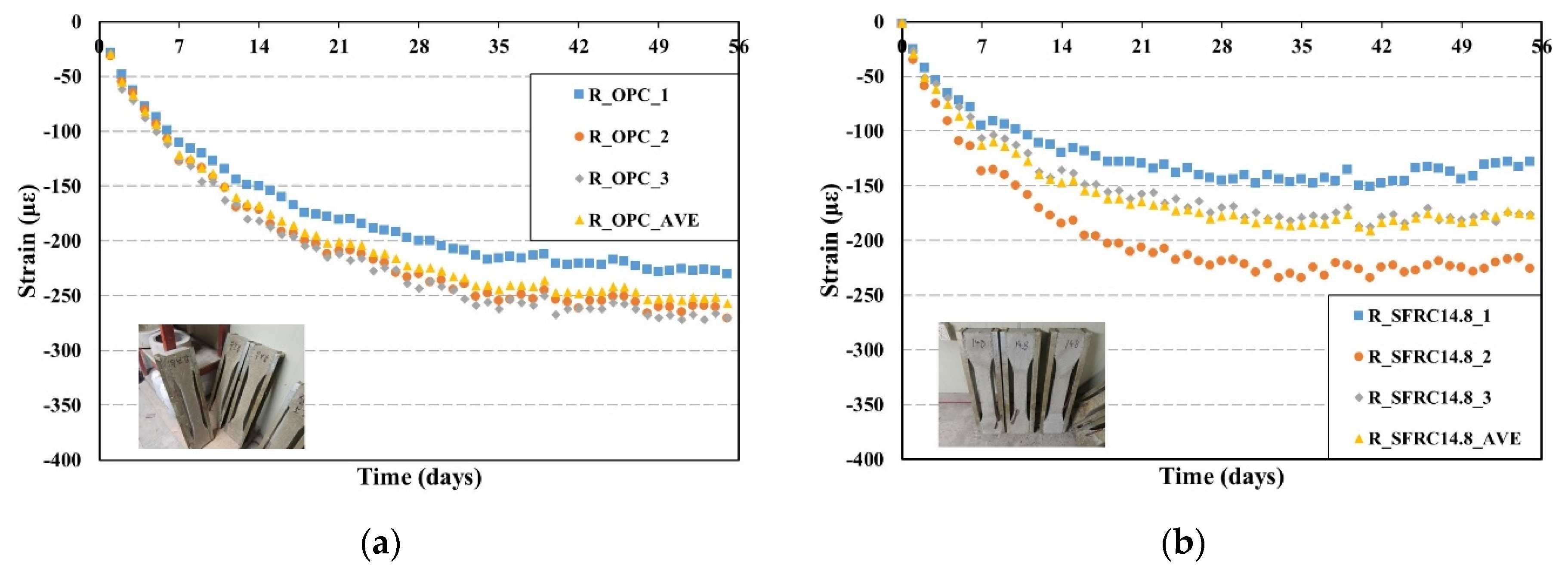
3.2. Restrained Drying Shrinkage Test Results
Figure 6a shows the restrained drying shrinkage strain results of the plain concrete specimens in terms of aging (days). The strain ranged from 230 to 270 με after 56 days of aging even with slight differences among the specimens.
Figure 6b shows the strain of the SFRC14.8 specimens. The strain ranged from 127 to 225 με after 56 days of aging. The SFRC14.8 specimens exhibited approximately 31.3% less drying shrinkage strain than shown by the plain concrete specimens. Large differences in strain are evident among the SFRC14.8 specimens, which may be due to the steel fibers not being evenly distributed inside the specimens because of the low level of dispersion of the fibers when the concrete was poured.
3.3. Deck Slab Drying Shrinkage Tests
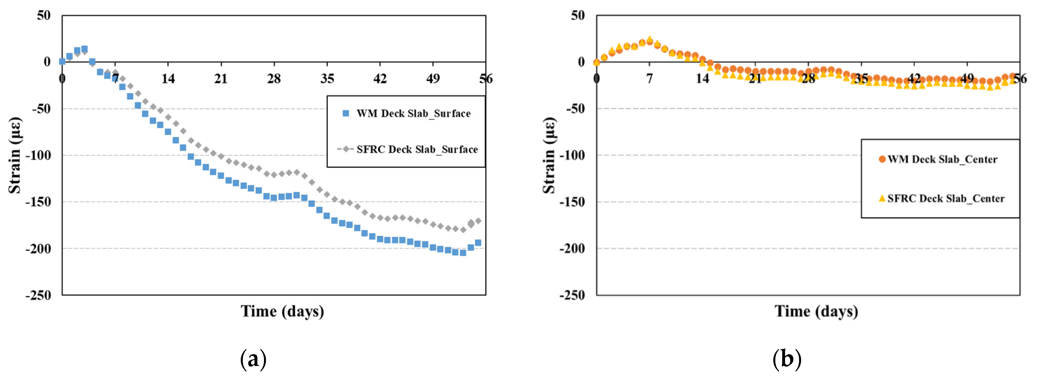
Figure 7 shows the aging results for the drying shrinkage strain measured by the gauges embedded at the surface and at the center of each deck slab specimen. For the surface measurements, the strain increased at the beginning but decreased after three days of aging due to the drying shrinkage of the concrete that occurred on the surface. The tendency of the drying shrinkage strain of the wire mesh deck slab to decrease is similar to that of the SFRC deck slab; however, the drying shrinkage strain of the wire mesh deck slab increased more than that of the SFRC deck slab as the aging progressed. After 56 days of aging, the drying shrinkage strain of the SFRC deck slab at the surface was approximately 12.4% less than that of the wire mesh deck slab. The reason for this outcome may be that the significant concrete drying shrinkage occurred in the part of the wire mesh deck slab that did not contain wire mesh, as only the upper part of the concrete was reinforced with wire mesh, whereas for the SFRC deck slab, the entire cross-section of the concrete was reinforced with arched steel fiber.
With regard to the drying shrinkage strain at the center of the specimen, the strain increased at the beginning (as it did at the surface), but started to decrease after seven days of aging. The strain continued to decrease and became almost constant after 16 days of aging. The likely reason for this outcome is that the drying shrinkage of the concrete at the bottom of the deck slab was restrained by the deck plate, whereas drying shrinkage occurred on the surface of the deck slab due to exposure to the external environment. Therefore, the drying shrinkage strain at the center of the specimen did not decrease with an increase in aging because compressive force acted on the top of the deck slab and tensile force acted on the bottom.
Figure 8 and
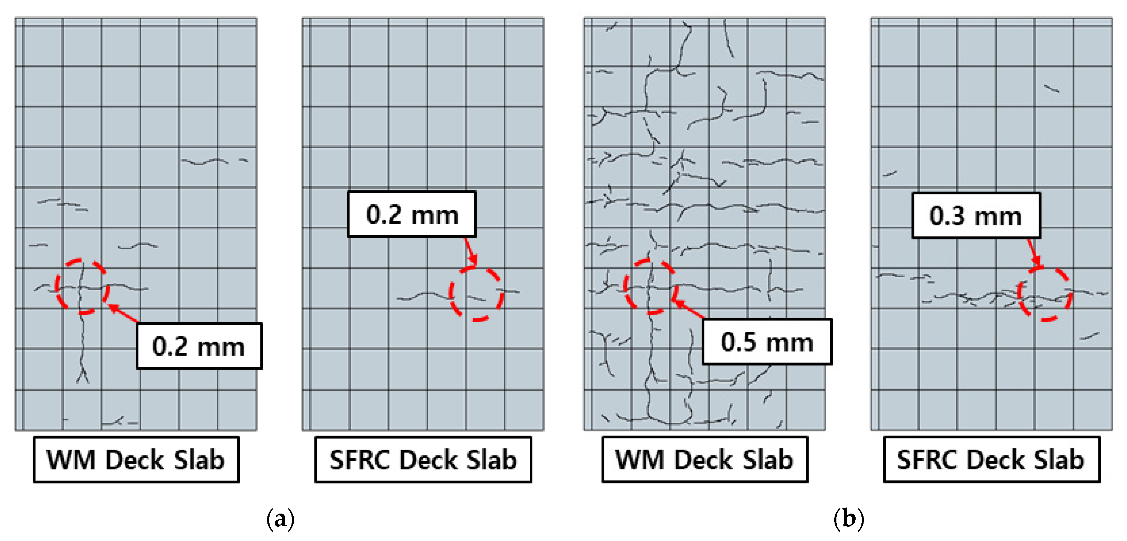
Table 5 present the crack geometry and widths of the cracks that appeared on the surface of the wire mesh deck slab and SFRC deck slab after aging for seven days and 56 days.
Figure 8a shows the crack geometry on the surface of the wire mesh and SFRC deck slabs after seven days of aging. At the beginning, cracks appeared on the surface of both the wire mesh and SFRC deck slabs due to plastic shrinkage. The average crack width is shown to be 0.1 mm, and the maximum crack width is 0.2 mm.
Figure 8b shows the crack geometry on the surface of the wire mesh and SFRC deck slabs after 56 days of aging. After 56 days of aging, drying shrinkage cracks appeared on the entire surface of the wire mesh deck slab, with crack widths ranging from 0.1 to 0.5 mm. In the case of the SFRC deck slab, drying shrinkage cracks appeared at the same location as the initial cracks that were due to plastic shrinkage, with crack widths ranging from 0.1 to 0.3 mm. This comparison of the crack geometry and crack width in terms of aging indicates that the SFRC deck slab can inhibit plastic shrinkage cracks that occur early more effectively than the wire mesh deck slab can, and that the SFRC deck slab also is more effective than the wire mesh slab in controlling the number of drying shrinkage cracks and the crack widths.
4. Drying Shrinkage Strain Prediction Model
The free-drying shrinkage of concrete is affected by environmental factors, such as curing conditions and relative humidity, and material factors, such as the surface area ratio, slump, compressive strength, and cement type. Thus, the free-drying shrinkage strain of concrete is predicted according to these factors. In this study, we predicted the free-drying shrinkage strain for plain concrete and concrete reinforced with arched steel fiber using the free-drying shrinkage prediction model for plain concrete suggested by the Korea Concrete Institute (KCI 2017) of South Korea [
11], ACI 209R-92 [
12] and GL2000 [
13,
14], which are free-drying shrinkage prediction models suggested in overseas codes and the literature, and the prediction model derived by Li (2017) [
15] that uses free-drying shrinkage tests of steel fiber-reinforced cement mortar.
4.1. KCI (2017) Prediction Model
The free-drying shrinkage strain prediction model suggested by the KCI follows the Comit Euro-International du B ton (CEB) and the F d ration International de la Pr contrainte CEB-FIP 1990 Model Code (1990) [
16]. The KCI prediction model can predict free-drying shrinkage strain according to time, relative humidity, concrete surface area ratio, compressive strength, and cement type. The free-drying shrinkage strain at the age of the concrete (
t) can be predicted using Equations (1)–(5).
where
t = age of concrete
tc = start date of drying shrinkage
εsh = drying shrinkage strain
βcs = 4: Type II cement, 5: Type I and Type V cement, 8: Type III cement
fcm28 = compressive strength of concrete at 28 days
h = relative humidity (0.4 ≤ h ≤ 0.99)
βRH = drying shrinkage influence coefficient according to the outside air humidity
V = volume of the specimen
S = area exposed to the atmosphere
4.2. ACI 209R-92 (2008) Prediction Model
The free-drying shrinkage strain prediction model suggested in ACI 209R-92 [
12] obtains the drying shrinkage strain according to the external environment and the material properties of concrete, such as the concrete curing conditions, relative humidity, surface area ratio, slump, and fine aggregate content. Equation (6) is the prediction model, and Equations (7) and (8) express the shape factor and maximum drying shrinkage strain, respectively. The drying shrinkage correction factors are expressed in Equation (9).
where
f = shape factor
εshu = maximum drying shrinkage strain
γsh = drying shrinkage correction factor
γtc = curing period correction factor
γRH = relative humidity correction factor
γVS = surface area ratio correction factor
γs = slump correction factor
γϕ = fine aggregate content correction factor
γc = cement content correction factor
γα = air content correction factor
4.3. Comparisons between Test Results and Prediction Model Results
Each prediction model predicts the drying shrinkage strain based on different environmental and material factors. For the F-OPC and F-SFRC20 specimens, we compared the free-drying shrinkage strain results obtained using the prediction models with the test results.
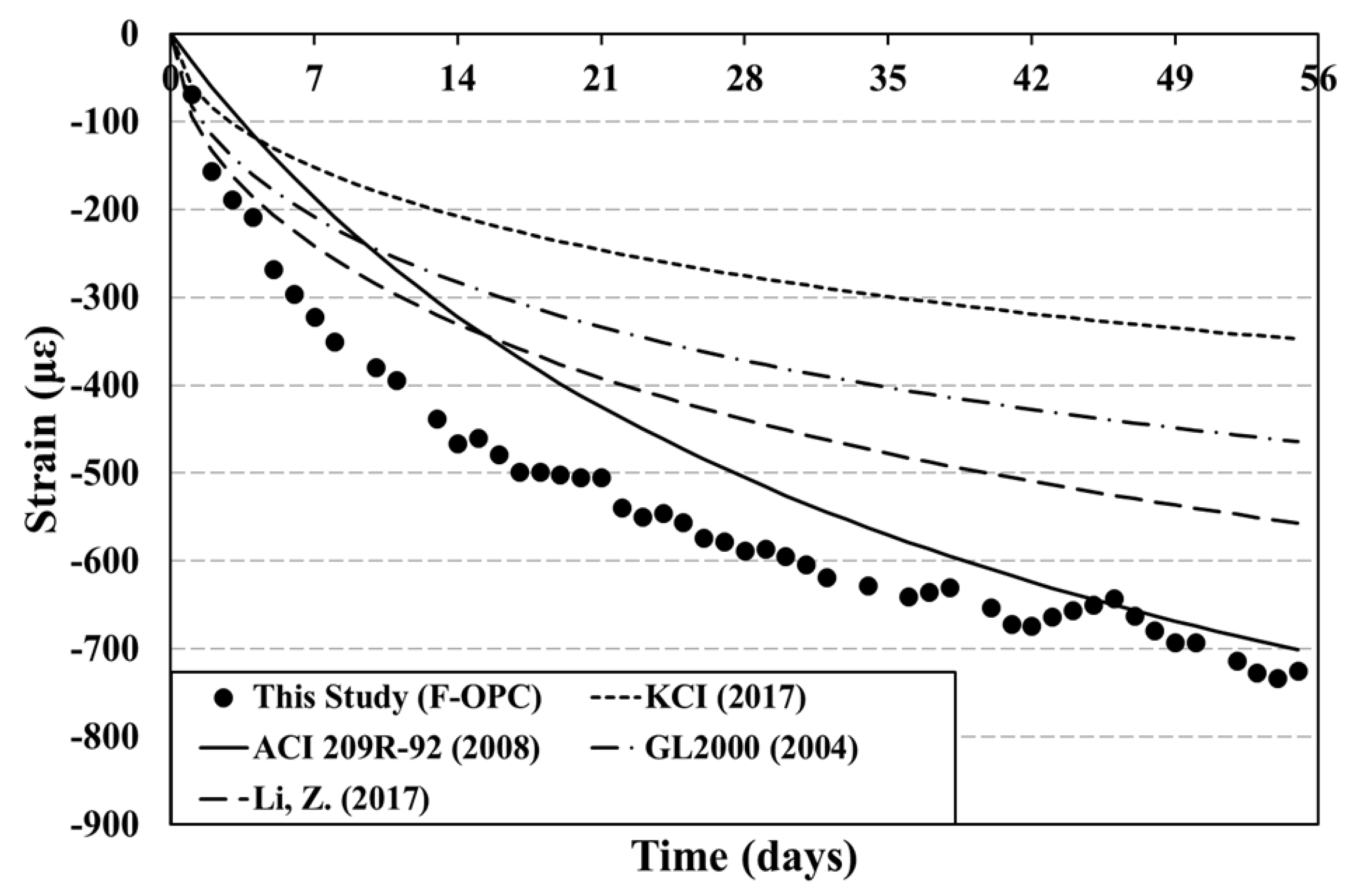
Figure 9 and
Table 6 present comparisons of the free-drying shrinkage strain measurements of the plain concrete that were obtained via each prediction model versus the free-drying shrinkage test results.
Figure 9 shows that the KCI [
11], GL2000 [
13,
14], and Li [
15] prediction model results are similar to the experimental results for the first three days of aging, but the predicted drying shrinkage strain levels decrease as the aging increases. The reason for this outcome may be that the KCI and GL2000 prediction models evaluate the material properties of concrete using only cement type and concrete strength as the variables. On the other hand, for the ACI 209R-92 prediction model results, the predicted strain is lower than the experimental results initially, but becomes similar to the experiment results as the aging increases. The reason for this outcome appears to be that the ACI 209R-92 prediction model applies detailed coefficient values that consider the slump, fine aggregate content, and air content of concrete.
A comparison of the prediction results and experimental results for the drying shrinkage strain of the plain concrete at 56 days of aging shows that the KCI prediction model has the largest error of −52% and the ACI 209R-92 prediction model has the smallest error of −4 percent.
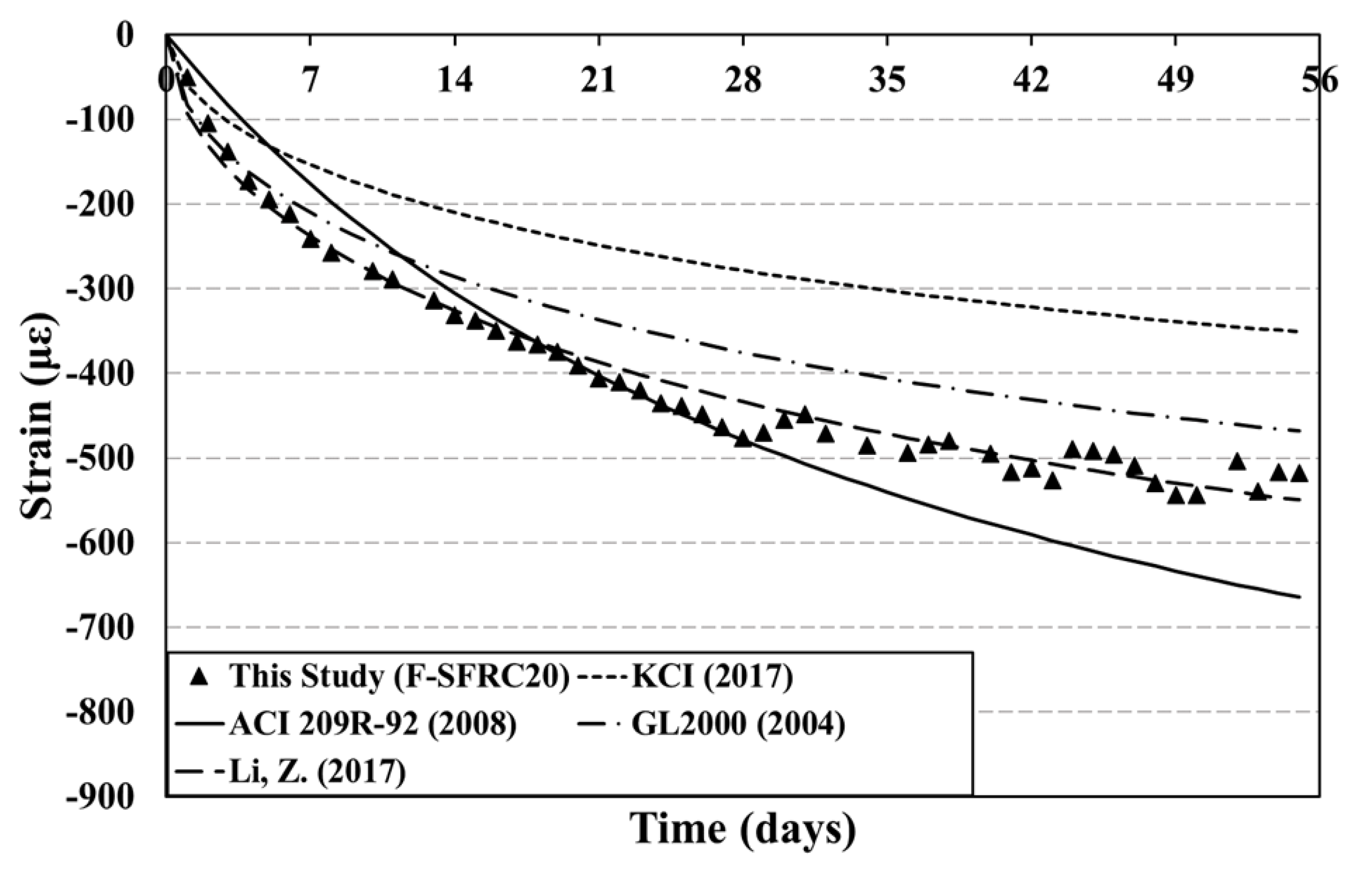
Figure 10 and
Table 7 present comparisons of the free-drying shrinkage strain results for SFRC20 that were obtained via each prediction model versus the free-drying shrinkage test results. When the predicted results are compared with the experimental results by age of the concrete, the KCI and GL2000 prediction model results are similar to the experimental results initially, but the differences become greater and the strain levels decrease as aging increases, which is similar to the plain concrete results. In the case of the ACI 209R-92 prediction model, the prediction results also are similar to the test results until 28 days of aging, but are overestimated after 28 days. The reason for this outcome may be that the drying shrinkage of concrete is mitigated by the steel fiber as the drying shrinkage strain increases for SFRC20, but this effect is not reflected in the prediction models suggested by domestic and overseas codes for concrete. The Li prediction model results are the most similar to the test results for SFRC20 throughout the aging times among the four models, even though slight differences are evident for the plain concrete. The reason for this outcome may be that the Li prediction model considers the fine aggregate and steel fiber contents that affect drying shrinkage when calculating the maximum drying shrinkage strain of concrete.
A comparison of the predicted and test results for the drying shrinkage strain of SFRC20 at 56 days of aging indicates that the KCI prediction model shows the largest error of −32% and the Li prediction model has the smallest error of +6%.
5. Conclusions
This study investigates drying shrinkage of SFRC associated with the inclusion rate of arched steel fibers.
As a result of the free-drying shrinkage test of plain concrete and concrete reinforced with 20 k/m3 of arched steel fibers, the drying shrinkage strain was reduced by about 28.6%. In addition, as a result of carrying out a confined drying shrinkage test of concrete with the mixing rate of arched steel fibers as a variable, in the case of concrete reinforced with 14.8 kg/m3 of arched steel fibers, the drying shrinkage strain was reduced by about 31.3% compared to that of plain concrete.
As a result of comparing the strain rate according to the minimum mixing rate suggested by the KCI specifications, it was found that it was similar in the initial section.
As a result of comparing the strain rate of concrete reinforced with 20 kg/m3 of arched steel fiber according to the minimum mixing rate suggested by the ACI 209R specification, it was possible to sufficiently predict the drying shrinkage strain rate through the prediction model proposed by the ACI 209R code during the age of 28 days.
However, the result found that the arch shape of the steel fiber and the tensile strength of the steel fiber affect the drying shrinkage of concrete, and after 28 days, the model predicted by the ACI 209R code predicted the most similar results.
Author Contributions
Conceptualization, D.-J.K. and W.-C.C.; methodology, W.-C.C.; formal analysis, D.-J.K. and S.-H.K.; investigation, D.-J.K. and S.-H.K.; writing—original draft preparation, D.-J.K.; writing—review and editing, S.-H.K. and W.-C.C.; supervision, W.-C.C.; project administration, W.-C.C.; funding acquisition, W.-C.C. All authors have read and agreed to the published version of the manuscript.
Funding
This research was funded by the Gachon University research fund of 2020 (GCU-202002560001).
Institutional Review Board Statement
Not applicable.
Informed Consent Statement
Not applicable.
Data Availability Statement
The data presented in this study are available based on request from the corresponding author.
Conflicts of Interest
The authors declare no conflict of interest.
References
- Yuan, T.-F.; Yoo, D.-Y.; Yang, J.-M.; Yoon, Y.-S. Shear capacity contribution of steel fiber reinforced high-strength concrete compared with and without stirrup. Int. J. Concr. Struct. Mater. 2020, 14, 21. [Google Scholar] [CrossRef]
- Nakov, D.; Markovski, G.; Arangjelovski, T. Influence of steel fibre reinforcement on the properties of concrete. In Proceedings of the 1st International Conference Construction Materials for Sustainable Future CoMS, Zadar, Croatia, 19–21 April 2017; Volume 1. [Google Scholar]
- ACI 360R-06. Design of Slabs-on-Ground; American Concrete Institute: Indianapolis, IN, USA, 2006. [Google Scholar]
- Steel Deck Institute. ANSI/SDI C-2017 Standard for Composite Steel Floor Deck-Slabs; Steel Deck Institute: Allison Park, PA, USA, 2017. [Google Scholar]
- Yoon, E.S.; Park, S.B. An experimental study on the mechanical properties and long-term deformations of high-strength steel fiber reinforced concrete. J. Civil. Environ. Eng. Res. 2006, 26, 401–409. [Google Scholar]
- Bandelj, B.; Saje, D.; Šušteršič, J.; Lopatič, J.; Saje, F. Free shrinkage of high performance steel fibre reinforced concrete. J. Test. Eval. 2011, 39, 166–176. [Google Scholar]
- Kim, S.D.; Choi, K.K.; Choi, S.J. Characteristics of restrained drying shrinkage cracking of amorphous steel fiber-reinforced concrete. J. Archit. Inst. Korea Struct. Constr. 2014, 30, 63–70. [Google Scholar]
- Won, J.P.; Lee, J.H.; Lee, S.J. Bonding behavoiur of arch-type steel fibres in a cementitious composite. Compos. Struct. 2015, 133, 117–123. [Google Scholar] [CrossRef]
- KS F 2424, Standard Test Method for Length Change of Mortar and Concrete, 2020; Korea Industrial Standards: Seoul, Korea, 2020.
- KS F 2595, Standard Test Method for Drying Shrinkage Crack in Concrete, 2021; Korea Industrial Standards: Seoul, Korea, 2021.
- Korea Concrete Institute. Concrete Design Code and Commentary; Korea Concrete Institute: Seoul, Korea, 2017. [Google Scholar]
- ACI 209R. Guide for Modeling and Calculating Shrinkage and Creep in Hardened Concrete; American Concrete Institute: Indianapolis, IN, USA, 1992. [Google Scholar]
- Gardner, N.J. Comparison of prediction provisions for drying shrinkage and creep of normal strength concretes. Can. J. Civil. Eng. 2004, 31, 767–775. [Google Scholar] [CrossRef]
- Gardner, N.J.; Lockman, M.J. Design provisions for drying shrinkage and creep of normal-strength concrete. ACI Mater. J. 2001, 98, 159–167. [Google Scholar]
- Li, Z. Predicting the drying shrinkage behavior of high strength portland cement mortar under the combined influence of fine aggregate and steel micro fiber. Mater. De Construcción 2017, 67, 119. [Google Scholar] [CrossRef] [Green Version]
- CEB-FIP (Comité Euro-International du Béton-Fédération Internationale de la Précontrainte). CEB-FIP Model Code 1990: Design Code, 1st ed.; Information Bulletin, No 195; CEB-FIP: Lausanne, Switzerland, 1990. [Google Scholar]
Figure 1.
Restrained drying shrinkage test specimens: (
a) dimensions for the specimen [
10], (
b) plain concrete, and (
c) SFRC 14.8.
Figure 1.
Restrained drying shrinkage test specimens: (
a) dimensions for the specimen [
10], (
b) plain concrete, and (
c) SFRC 14.8.
Figure 2.
Cross-section of deck plate.
Figure 2.
Cross-section of deck plate.
Figure 3.
Cross-section of deck specimens: (a) SFRC deck slab and (b) wire mesh deck slab.
Figure 3.
Cross-section of deck specimens: (a) SFRC deck slab and (b) wire mesh deck slab.
Figure 4.
Fabrication of deck slab: (a) SFRC slab, (b) control slab, (c) measurement set-up, and (d) crack measurement.
Figure 4.
Fabrication of deck slab: (a) SFRC slab, (b) control slab, (c) measurement set-up, and (d) crack measurement.
Figure 5.
Free-drying shrinkage strain during aging: (a) plain concrete and (b) concrete reinforced with arched steel fiber content of 20 kg/m3.
Figure 5.
Free-drying shrinkage strain during aging: (a) plain concrete and (b) concrete reinforced with arched steel fiber content of 20 kg/m3.
Figure 6.
Restrained drying shrinkage strain during aging: (a) plain concrete and (b) concrete reinforced with arched steel fiber content of 14.8 kg/m3.
Figure 6.
Restrained drying shrinkage strain during aging: (a) plain concrete and (b) concrete reinforced with arched steel fiber content of 14.8 kg/m3.
Figure 7.
Deck slab drying shrinkage strain during aging: (a) at surface and (b) at center of deck slab.
Figure 7.
Deck slab drying shrinkage strain during aging: (a) at surface and (b) at center of deck slab.
Figure 8.
Crack geometry and crack widths after aging for wire mesh (WM) deck slabs and steel fiber-reinforced concrete (SFRC) deck slabs: (a) 7 days and (b) 56 days.
Figure 8.
Crack geometry and crack widths after aging for wire mesh (WM) deck slabs and steel fiber-reinforced concrete (SFRC) deck slabs: (a) 7 days and (b) 56 days.
Figure 9.
Comparison of test results (‘This Study’) versus prediction model results for the drying shrinkage strain of plain concrete.
Figure 9.
Comparison of test results (‘This Study’) versus prediction model results for the drying shrinkage strain of plain concrete.
Figure 10.
Comparison of test results (‘This Study’) versus prediction model results for the drying shrinkage strain of SFRC20.
Figure 10.
Comparison of test results (‘This Study’) versus prediction model results for the drying shrinkage strain of SFRC20.
Table 1.
Geometric and physical properties of arched steel fiber.
Table 1.
Geometric and physical properties of arched steel fiber.
| Type | Fiber Length
(L) (mm) | Fiber Diameter
(d) (mm) | Tensile Strength
(MPa) | Aspect Ratio
(L/d) |
|---|
![Applsci 11 07537 i001]()
Arched | 60 | 0.75 | 1500 | 80 |
Table 2.
Mixture Proportions.
Table 2.
Mixture Proportions.
f’c
(MPa) | W/C
(%) | Unit Weight (kg/m3) |
|---|
| Water | Cement | FA | CA | WRA |
|---|
| 24 | 47.4 | 174 | 367 | 873 | 921 | 2.94 |
Table 3.
Variables used in drying shrinkage tests.
Table 3.
Variables used in drying shrinkage tests.
| Identification | f’c
(MPa) | Steel Fiber Type | Steel Fiber Tensile Strength (MPa) | Steel Fiber Aspect Ratio (L/d) | Steel Fiber Content (kg/m3) |
|---|
| OPC | 44.9 | - | - | - | - |
| SFRC14.8 | 46.3 | Arched | 1500 | 80 | 14.8 |
| SFRC20 | 44.1 | 20 |
Table 4.
Mechanical properties of deck plate.
Table 4.
Mechanical properties of deck plate.
| Category | Identification | Mechanical Properties |
|---|
| Yielding Point (N/mm2) | Tensile Strength (N/mm2) | Elongation (%) |
|---|
| Top deck slab | SGC400 | 295 | 400 | 18 |
Table 5.
Crack width measurements after aging: 7 Days and 56 Days.
Table 5.
Crack width measurements after aging: 7 Days and 56 Days.
| Specimen Name | 7 Days of Aging | 56 Days of Aging |
|---|
Average Crack Width
(mm) | Maximum Crack Width
(mm) | Average Crack Width
(mm) | Maximum Crack Width
(mm) |
|---|
| Wire mesh deck slab | 0.1 | 0.2 | 0.1~0.2 | 0.5 |
| SFRC deck slab | 0.1 | 0.2 | 0.1~0.2 | 0.3 |
Table 6.
Comparison of test results (‘This Study’) versus prediction model results for the drying shrinkage strain of plain concrete (F-OPC) at 56 Days.
Table 6.
Comparison of test results (‘This Study’) versus prediction model results for the drying shrinkage strain of plain concrete (F-OPC) at 56 Days.
| F-OPC | Drying Shrinkage Strain at 56 Days (με) | Predicted Value/Experimental Value |
|---|
| This study | 725 | - |
| KCI (2017) | 347 | 0.48 |
| ACI 209R-92 (2008) | 701 | 0.96 |
| GL2000 (2004) | 464 | 0.64 |
| Li Z. (2017) | 557 | 0.77 |
Table 7.
Comparison of test results (‘This Study’) versus prediction model results for the drying shrinkage strain of SFRC20 at 56 days.
Table 7.
Comparison of test results (‘This Study’) versus prediction model results for the drying shrinkage strain of SFRC20 at 56 days.
| F-SFRC20 | Drying Shrinkage Strain at 56 Days (με) | Predicted Value/Experimental Value |
|---|
| This study | 518 | - |
| KCI (2017) | 351 | 0.68 |
| ACI 209R-92 (2008) | 664 | 1.28 |
| GL2000 (2004) | 468 | 0.90 |
| Li Z. (2017) | 549 | 1.06 |
| Publisher’s Note: MDPI stays neutral with regard to jurisdictional claims in published maps and institutional affiliations. |
© 2021 by the authors. Licensee MDPI, Basel, Switzerland. This article is an open access article distributed under the terms and conditions of the Creative Commons Attribution (CC BY) license (https://creativecommons.org/licenses/by/4.0/).


