
Analysis and Design of Single-Phase Unidirectional Transducers with High Directivity

 ,
, 
 and
and 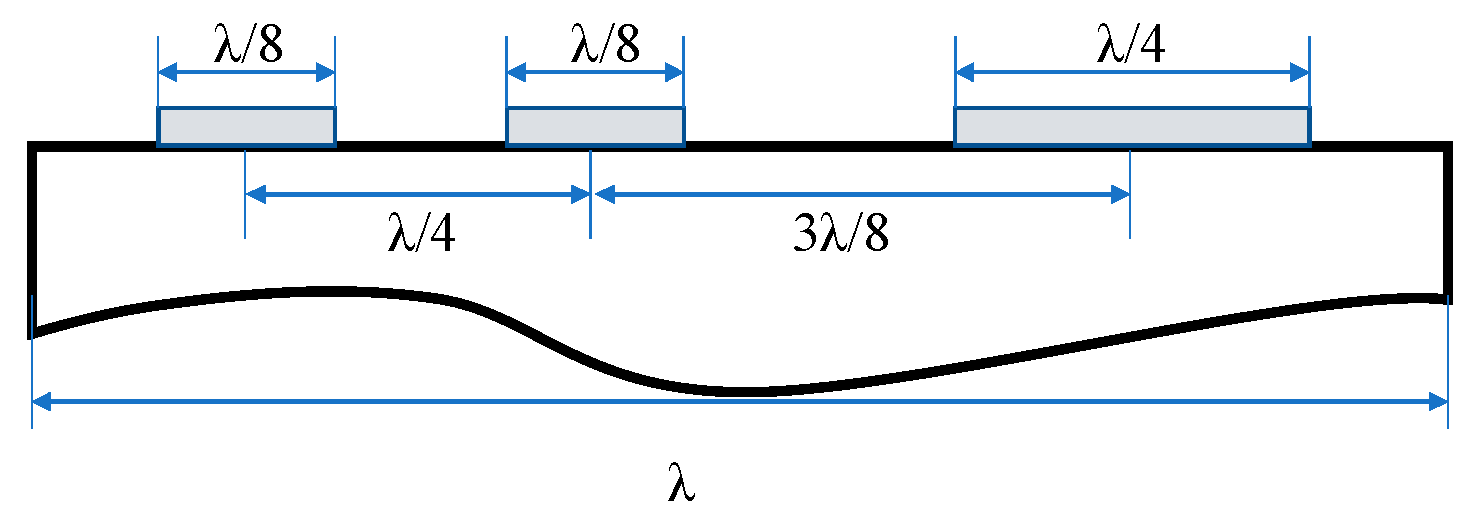
Abstract
:1. Introduction
2. Design and Optimization
3. Fabrication Technologies
4. Experimental Results and Discussion
5. Conclusions
Author Contributions
Funding
Institutional Review Board Statement
Informed Consent Statement
Data Availability Statement
Conflicts of Interest
Appendix A


References
- Wang, W.; Shao, X.; Liu, X.; Liu, J.; He, S. Enhanced sensitivity of Surface acoustic wave-based rate sensors incorporating metallic dot arrays. Sensors 2014, 14, 3908–3920. [Google Scholar]
- Lu, R.; Manzaneque, T.; Yang, Y.; Li, M.H.; Gong, S. Gigahertz low-loss and wideband S0 mode lithium niobate acoustic delay lines. IEEE Trans. Ultrason. Ferroelectr. Fre. Control. 2019, 66, 1373–1386. [Google Scholar] [CrossRef]
- Chung, M.H.; Hwang, R.C.; Chiu, J.J.; Yang, M.W.; Hung, T.T.; Shen, C.Y. Enhanced sensitive surface acoustic wave device designed for nitric oxide gas detection. Sensor Mater. 2019, 31, 2195–2212. [Google Scholar] [CrossRef]
- Manzaneque, T.; Lu, R.; Yang, Y.; Gong, S. Low-loss and wideband acoustic delay lines. IEEE Trans. Microw. Theory Tech. 2019, 67, 1379–1391. [Google Scholar] [CrossRef]
- Kodama, T.; Kawabata, H.; Sato, H.; Yasuhara, Y. Design of low-loss SAW filters employing distributed acoustic reflection transducers. In Proceedings of the IEEE Ultrasonics Symposium, Williamsburg, VA, USA, 17–19 November 1986; pp. 59–64. [Google Scholar] [CrossRef]
- Hartmann, C.S.; Abbott, B.P. Overview of design challenges for single phase unidirectional SAW filters. In Proceedings of the IEEE Ultrasonics Symposium, Montreal, QC, Canada, 3–6 October 1989; pp. 79–89. [Google Scholar] [CrossRef]
- Yamanouchi, K.; Furuyashiki, H. Low-loss SAW filter using internal reflection types of new single-phase unidirectional transducer. In Proceedings of the IEEE Ultrasonics Symposium, Dallas, TX, USA, 14–16 November 1984; pp. 68–71. [Google Scholar] [CrossRef]
- Chvets, V.B.; Ivanov, P.G.; Makarov, V.M.; Orlov, V.S. Low-loss SAW filters using new SPUDT structures. In Proceedings of the IEEE Ultrasonics Symposium, Toronto, ON, Canada, 5–8 October 1997; pp. 69–72. [Google Scholar] [CrossRef]
- Galipeau, J.D. Enhanced SPUDT cells for high coupling substrates. In Proceedings of the IEEE Ultrasonics Symposium, Rotterdam, The Netherlands, 18–21 September 2005; pp. 1052–1055. [Google Scholar] [CrossRef]
- Shui, Y.; Lin, J.M.; Wu, H.; Wang, N.; Chen, H. Optimization of single-phase, unidirectional transducers using three fingers per period. IEEE Trans. Ultrason. Ferroelectr. Fre. Control 2002, 49, 1617–1621. [Google Scholar] [CrossRef]
- Hashimoto, K.Y.; Zheng, G.Q.; Yamaguchi, M. Fast analysis of SAW propagation under multi-electrode-type gratings with finite thickness. In Proceedings of the IEEE Ultrasonics Symposium, Toronto, ON, Canada, 5–8 October 1997; pp. 279–284. [Google Scholar] [CrossRef]
- Li, H.; Wen, J.; Hashimoto, K.Y.; Omori, T.; Yamaguchi, M. Low-loss and constant-group-delay surface acoustic wave filters employing Cu-based resonant single-phase unidirectional transducers. Jpn. J. Appl. Phys. 2006, 45, 4655–4657. [Google Scholar] [CrossRef]
- Nakagomi, S.; Asano, H.; Tanaka, H.; Omori, T.; Hashimoto, K.Y.; Yamaguchi, M. Single-phase unidirectional surface acoustic wave transducer using Cu electrode. Jpn. J. Appl. Phys. 2003, 42, 3152–3156. [Google Scholar] [CrossRef]
- Plessky, V.; Koskela, J. Coupling-of-modes analysis of SAW devices. Int. J. High Speed Electron. Syst. 2000, 10, 867–947. [Google Scholar] [CrossRef]
- Tian, Y.; Li, H.; Ke, Y.; Yuan, C.; He, S. P-Matrix Analysis of Surface Acoustic Waves in Piezoelectric Phononic Crystals. IEEE Trans. Ultrason. Ferroelectr. Fre. Control 2016, 63, 757–763. [Google Scholar] [CrossRef]
- Mayer, M.; Dadgar-Javid, G.; Ebner, T.; Wagner, K. Causal P-matrix description of leaky SAW devices. In Proceedings of the IEEE Ultrasonics Symposium, Tours, France, 18–21 September 2016; pp. 1–4. [Google Scholar] [CrossRef]
- Abbott, B.P.; Hartmann, C.S.; Malocha, D.C. Matching of single-phase unidirectional SAW transducers and a demonstration using a low-loss EWC/SPUDT filter. In Proceedings of the IEEE Ultrasonics Symposium, Honolulu, HI, USA, 4–7 December 1990; pp. 49–54. [Google Scholar] [CrossRef]
- Lin, J.; Wang, N.; Chen, H.; Shui, Y. Fast, precise, and full extraction of the COM parameters for multielectrode-type gratings by periodic Green’s function method. IEEE Trans. Ultrason. Ferroelectr. Fre. Control 2002, 49, 1735–1738. [Google Scholar] [CrossRef]
- Chen, D.P.; Haus, H.A. Analysis of metal-strip SAW gratings and transducers. IEEE Trans. Sonics Ultrason 1985, 32, 395–408. [Google Scholar] [CrossRef]
- Sun, X.; Liu, W.; Ge, S.; Zhou, S.; Li, X.; Lin, D. Achieving both high electromechanical response and stable temperature behavior in Si/SiO2/Al/LiTaO3 sandwich structure. AIP Adv. 2019, 9, 35145. [Google Scholar] [CrossRef] [Green Version]
- Zhang, Y.M.; Jin, J.; Li, H.L.; Hu, H.P. A novel method to extract COM parameters for SAW based on FEM. In Proceedings of the 2019 13th Symposium on Piezoelectrcity, Acoustic Waves and Device Applications (SPAWDA), Harbin, China, 11–14 January 2019; pp. 1–5. [Google Scholar] [CrossRef]
- Carmichael, C.; Malocha, D.C.; Weeks, A. Asymmetric energy coupling through acoustoelectric effect using graphene on lithium niobite surface acoustic wave delay line in GHz Range. In Proceedings of the IEEE Ultrasonics Symposium, Glasgow, UK, 6–9 October 2019; pp. 702–705. [Google Scholar] [CrossRef]
- Sun, X.; Liu, W.; Shao, X.; Zhou, S.; Wang, W.; Lin, D. Surface acoustic wave gyroscopic effect in an interdigital transducer. Sensors 2018, 19, 106. [Google Scholar] [CrossRef] [PubMed] [Green Version]
- Solal, M.; Chen, L.; Gratier, J. Measurement and FEM/BEM simulation of transverse effects in SAW resonators on lithium tantalite. IEEE Trans. Ultrason. Ferroelectr. Fre. Control 2013, 60, 2404–2413. [Google Scholar] [CrossRef]
- Dufilie, P.; Ventura, P.; Hecht, F. COM parameters for thick metal and partially buried electrodes extracted from a mixed FEM/BEM numerical model. In Proceedings of the IEEE Ultrasonics Symposium, Dresden, Germany, 7–10 October 2012; pp. 807–810. [Google Scholar] [CrossRef]
- Matsuoka, N.; Li, X.; Omori, T.; Hashimoto, K.Y. Study of loss mechanisms in temperature compensated surface acoustic wave devices based on finite element method analysis using hierarchical cascading technique. Jpn. J. Appl. Phys. 2020, 59, SKKC06. [Google Scholar] [CrossRef]
- Wang, T.; Green, R.; Guldiken, R.; Wang, J.; Mohapatra, S.; Mohapatra, S.S. Finite element analysis for surface acoustic wave device characteristic properties and sensitivity. Sensors 2019, 19, 1749. [Google Scholar] [CrossRef] [Green Version]
- Xiao, Q.; Dai, M.; Chen, J.; Fan, Y.P.; Cai, P.; Ji, X.J. Surface acoustic wave characteristics with a layered structure of IDT/θ° YX-LiTaO3/SiO2/AlN /diamond. Acoust. Phys. 2020, 65, 652–657. [Google Scholar] [CrossRef]
- Koskela, J.; Plessky, V. Hierarchical Cascading in FEM Simulations of SAW Devices. In Proceedings of the IEEE Ultrasonics Symposium, Kobe, Japan, 22–25 October 2018; pp. 1–11. [Google Scholar] [CrossRef]
- Xie, Q.; Hu, Y.; Zhao, X.; Wang, F.; Tang, Y.; Zhang, Q.; Chen, M.; Shi, W.; Lin, D.; Luo, H. Theoretical analysis of high electromechanical coupling surface acoustic wave propagating on lead-free Na0.5Bi0.5TiO3–BaTiO3 single crystal. Scripta Mater 2020, 178, 372–375. [Google Scholar] [CrossRef]
- Li, X.; Bao, J.; Qiu, L.; Matsuoka, N.; Omori, T.; Hashimoto, K.Y. 3D FEM simulation of SAW resonators using hierarchical cascading technique and general purpose graphic processing unit. Jpn. J. Appl. Phys. 2019, 58, SGGC05. [Google Scholar] [CrossRef]
- Dühring, M.B.; Laude, V.; Khelif, A. Energy storage and dispersion of surface acoustic waves trapped in a periodic array of mechanical resonators. J. Appl. Phys. 2009, 105, 093504. [Google Scholar] [CrossRef] [Green Version]
- Graczykowski, B.; Alzina, F.; Gomis-Bresco, J.; Sotomayor Torres, C.M. Finite element analysis of true and pseudo surface acoustic waves in one-dimensional phononic crystals. J. Appl. Phys. 2015, 119, 025308. [Google Scholar] [CrossRef]
- Maouhoub, S.; Aoura, Y.; Mir, A. FEM simulation of AlN thin layers on diamond substrates for high frequency SAW devices. Diam. Relat. Mater. 2016, 62, 7–13. [Google Scholar] [CrossRef]
- Maouhoub, S.; Aoura, Y.; Mir, A.J.M.E. FEM simulation of rayleigh waves for SAW devices based on ZnO/AlN/Si. Microelectron. Eng. 2015, 136, 22–25. [Google Scholar] [CrossRef]
- Hartmann, C.S.; Jen, S.; Martin, T.A. A compact high-performance EWC/SPUDT SAW Channelizer. In Proceedings of the IEEE Ultrasonics Symposium, Prague, Czech Republic, 21–25 July 2013; pp. 1395–1398. [Google Scholar] [CrossRef]
- Hashimoto, K.Y. Surface Acoustic Wave Devices in Telecommunications Modeling and Simulation; Springer: New York, NY, USA, 2000; pp. 191–235. [Google Scholar]
- Biryukov, S.V.; Martin, G.; Schmidt, H.; Wall, B. SPUDT cell with one-wavelength period and quarter-wavelength electrodes. In Proceedings of the IEEE Ultrasonics Symposium, Orlando, FL, USA, 18–21 October 2011; pp. 1337–1340. [Google Scholar] [CrossRef]
- Ito, H.; Hasegawa, K.; Matsuki, T.; Kusumoto, S. Lift-off photoresists for advanced IC packaging metal patterning. In Proceedings of the 16th International Conference on Electronic Packaging Technology (ICEPT), Changsha, China, 11–14 August 2015; pp. 1352–1356. [Google Scholar] [CrossRef]
- Berkoh, D.; Kulkarni, S. Challenges in Lift-Off Process Using CAMP Negative Photoresist in III–V IC Fabrication. IEEE Trans. Semicond. Manuf. 2019, 32, 513–517. [Google Scholar] [CrossRef]
- Kanouni, F.; Amara, S.; Assali, A.; Arab, F.; Qin, Z. A P-matrix-based model for the frequency analysis of IDT/AlScN/Sapphire SAW-delay Line. Sensor Actuat. A Phys. 2020, 307, 111980. [Google Scholar] [CrossRef]
- Abbott, B.P. Coupling-of-Modes Model for Saw Transducers with Arbitrary Reflectivity Weighting. Ph.D. Thesis, University of Central Florida, Orlando, FL, USA, 1989. [Google Scholar]
- Chen, Y.Y.; Wu, T.T.; Chou, T.T. Analysis of the frequency response of a dispersive IDT/ZnO/Sapphire SAW filter using effective permittivity and the coupling of modes model. J. Phys. D Appl. Phys. 2003, 37, 120–127. [Google Scholar] [CrossRef]


Publisher’s Note: MDPI stays neutral with regard to jurisdictional claims in published maps and institutional affiliations. |
© 2021 by the authors. Licensee MDPI, Basel, Switzerland. This article is an open access article distributed under the terms and conditions of the Creative Commons Attribution (CC BY) license (https://creativecommons.org/licenses/by/4.0/).
Share and Cite
Sun, X.; Ge, S.; Shao, X.; Zhou, S.; Wang, W.; Lin, D.; Liu, W. Analysis and Design of Single-Phase Unidirectional Transducers with High Directivity. Appl. Sci. 2021, 11, 7500. https://doi.org/10.3390/app11167500
Sun X, Ge S, Shao X, Zhou S, Wang W, Lin D, Liu W. Analysis and Design of Single-Phase Unidirectional Transducers with High Directivity. Applied Sciences. 2021; 11(16):7500. https://doi.org/10.3390/app11167500
Chicago/Turabian StyleSun, Xueping, Shaobo Ge, Xiuting Shao, Shun Zhou, Wen Wang, Dabin Lin, and Weiguo Liu. 2021. "Analysis and Design of Single-Phase Unidirectional Transducers with High Directivity" Applied Sciences 11, no. 16: 7500. https://doi.org/10.3390/app11167500
APA StyleSun, X., Ge, S., Shao, X., Zhou, S., Wang, W., Lin, D., & Liu, W. (2021). Analysis and Design of Single-Phase Unidirectional Transducers with High Directivity. Applied Sciences, 11(16), 7500. https://doi.org/10.3390/app11167500