Article

Thermal Performance Enhancement Using Absorber Tube with Inner Helical Axial Fins in a Parabolic Trough Solar Collector

by
Mohammad Zaboli
1,
Seyed Soheil Mousavi Ajarostaghi
2,
Seyfolah Saedodin
1 and
Mohsen Saffari Pour
3,*
1
Faculty of Mechanical Engineering, Semnan University, Semnan 47148-71167, Iran
2
Faculty of Mechanical Engineering, Babol Noshirvani University of Technology, Babol 47148-71167, Iran
3
Department of Mechanical Engineering, Faculty of Engineering, Shahid Bahonar University of Kerman, Kerman 76169-13439, Iran
*
Author to whom correspondence should be addressed.
Appl. Sci. 2021, 11(16), 7423; https://doi.org/10.3390/app11167423
Submission received: 20 May 2021 / Revised: 25 July 2021 / Accepted: 2 August 2021 / Published: 12 August 2021
(This article belongs to the Special Issue Experimental and Numerical Modeling of Fluid Flow)

Abstract

:
In the present work, a parabolic trough solar (PTC) collector with inner helical axial fins as swirl generator or turbulator is considered and analyzed numerically. The three-dimensional numerical simulations have been done by finite volume method (FVM) using a commercial CFD code, ANSYS FLUENT 18.2. The spatial discretization of mass, momentum, energy equations, and turbulence kinetic energy has been obtained by a second-order upwind scheme. To compute gradients, Green-Gauss cell-based method has been employed. This work consists of two sections where, first, four various geometries are appraised, and in the following, the selected schematic of the collector from the previous part is selected, and four various pitches of inner helical fins including 250, 500, 750 and 1000 mm are studied. All the numerical results are obtained by utilizing the FVM. Results show that the thermal performance improvement by 23.1% could be achieved by using one of the proposed innovative parabolic trough solar collectors compare to the simple one. Additionally, the minimum and maximum thermal performance improvement (compare to the case without fins) belong to the case with P = 250 mm by 14.1% and, to the case with P = 1000 mm by 21.53%, respectively.

1. Introduction

Heat exchangers, which transfer thermal energy through direct and indirect contact between fluids, are considered an indispensable part of several industries, from pharmaceutical to petrochemicals. Indirect contact heat exchangers are extensively used in solar systems. Due to the increasing importance of solar energy, nowadays, improving the performance of solar systems is one of the most important challenges for human beings and researchers. One of the most efficient types of solar collectors is a parabolic trough solar collector (PTSC), which is employed in both domestic and power plant applications. Recently, many efforts have been made by scientists to increase the efficiency of this type of collector. Actually, the PTSC component is a heat exchanger in which heat transfer fluid (HTF) flows in the receiver tube and absorbs the radiated solar energy.
In order to improve the thermal performance of this type of heat exchanger, various methods have been proposed and studied by researchers. Berger et al. [1] categorized heat exchangers’ augmentation procedures into passive and active subdivisions. One of two categories of ameliorating heat exchange methods is passive procedures [2]. It means that there is no requirement for any type of additional force. This method includes techniques such as nano particle [3], helical tubes [4], treated area [5], vortex generator [6], displaced increase devices [7], extended surfaces [8], and jagged surfaces [9].
Tang et al. [10] checked the heat transfer in the heat exchanger. According to their results, an increase of length enhances the performance of the vortex-generator fin. Azari et al. [11] checked the heat exchange in a heterogeneous circular microchannel, the results show the maximum heat exchange rates are got when the boundary conditions are symmetrical. Darzi et al. [12] have performed an experimental probing in a corrugated tube with nanofluid, they deduced that nanofluid with corrugated tubing could increase heat exchange by 330% compared to net liquid. Du et al. [13] numerically have worked on tube layouts, they demonstrated that the comprehensive efficiency of the optimized heat transfer device is ameliorated by about 50%. Bahiraei et al. [14] have checked on a triple-tube that their outcomes show that, based on heat exchange efficiency, an increase in height and reduced pitch are suggested. Abolarin et al. [15] have checked the impact of various geometries in twisted tapes, and the results pointed out that connection angle increases heat transfer. They found that when the wavelength is smaller, the temperatures near the walls increased. Zhang et al. [16] checked the thermal performance in corrugated pipes. According to the outcomes, the corrugated pipe ameliorated the heat transfer rate. Therefore, the other passive methods containing turbulator, etc., are usually better in the turbulent flow [17]. Several of the new works related to the utilization of inserts and the other passive methods to improve the thermal performance of the heat exchangers are displayed and listed in Table 1.
Solar energy is considered as a heat flux for solar collectors. The survey of a solar heat transfer device is trusted for increasing the thermal performance of the available system to obtain an outcome [41]. Moghaddaszadeh et al. [42] used two passive techniques to ameliorate the efficiency of heat exchangers in solar collectors. The outcomes illustrate that the use of nanofluid went up the Nusselt number up to 4%. Ghasemi and Ranjbar [43] in the numerical verification on solar parabolic collector demonstrated that adding nanoparticles increase thermal performance and using Al2O3 or CuO as nanofluid at 3% volume fraction enhances the heat exchange up to 28 and 35 percent, respectively. Reddy et al. [44] investigated the thermal analysis of parabolic trough collectors for various geometrical parameters such as porosity and fin aspect ratio. Their results pointed out that the porosity will increase the heat exchange by about 17%.
According to the presented literature review of previous works (Table 1) related to heat transfer enhancement of the PTSC by various passive methods, it can be concluded that among different kinds of utilized methods, employing helical axial fins has not been considered and analyzed previously. In the present work, one parabolic trough solar collector with inner helical axial fins as swirl generator or turbulator is considered and analyzed. This work consists of two sections. In the first section, four various schematics of the collector are appraised. In the second section, the selected geometry of the collector from the previous part (first section) is selected, and four various pitches of inner helical fins including 250, 500, 750 and 1000 mm are studied.

2. Materials, Methods and Boundary Conditions

Parabolic trough collector systems, as demonstrated in Figure 1a, in the studied geometry, a parabolic concentrator is used, which is due to the reduction of heat loss and increase of the produced temperature. Figure 1 shows the schematic of the checked geometry, and also Table 2 displays the geometrical constants and parameters. According to the check accomplished, for turbulent flow the entry region length is five times more than the diameter of the inner tube [35]; however, some researchers are of the opinion that it has a slight impact [45,46]. The three-dimensional numerical simulations have been done by finite volume method using commercial CFD code, ANSYS FLUENT 18.2. The geometrical parameters of the considered heat exchanger are illustrated in Figure 1c. The 30 °C inflow enters the tube at different velocities, namely 0.2, 0.24, 0.28 and 0.32 m·s−1. Velocity–inlet and pressure–outlet boundary conditions were considered at the inlet and outlet ports, respectively. A heat flux of 60,000 W·m−2 (is calculated by dividing the power consumption (6000 W) to the side surface area (0.10 m2) is transferred and applied to the outer part of the geometry made of an internally threaded steel layer. Moreover, the thermos–physical properties of tube material and fluid are noted in Table 3. The following situations are assumed in simulations:
  • The inlet fluid at all velocities is 30 °C.
  • The flow is turbulent and in a steady mood.
  • The heat flux applied to the surface of the outer tube is 60,000 W·m−2.
The present work includes two sections. In the first part, three geometries with various schematics of the inner helical axial fins are considered and investigated, and the obtained results are compared with the simple collector without any insert (fins). The schematics of the evaluated geometries in the first section of present work are illustrated in Figure 2. In the second section, the selected model according to the first section obtained results is considered with various pitch of the inner helical axial fins (P) including 250, 500, 750 and 1000 mm which the evaluated cases are depicted in Figure 3.

3. Governing Equations and Dimensionless Parameters

The actual system is governed by the continuity, momentum, and energy equations that are defined, respectively, as [47,48]:
ρ t + . ρ v = S m
ρ v t + . ρ v v = p + τ = + ρ g + F
ρ E t + . v ρ E + p = k e f f T j h j J j + τ = e f f . v + S h
The thermal performance coefficient (η) can be exerted to quantify the yield of a heat exchanger that contains the Nusselt number and the friction factor (f), and is defined as [49,50,51,52,53,54,55,56,57,58]:
N u = h m d h k
f = 2 d h Δ P ρ u 2 L
η = N u N u 0 f 0 f 1 3
The three-dimensional numerical simulations have been done by finite volume method using commercial CFD code, ANSYS FLUENT 18.2. The spatial discretization of the mass, momentum, turbulence kinetic energy, turbulence dissipation rate and energy equations has been achieved by a second-order upwind scheme. The velocity-pressure coupling has been overcome by the SIMPLE algorithm. To calculate the gradients, Green-Gauss cell-based method has been utilized. The convergence criteria were set to 10−6 for the residuals of all equations except energy equation (10−8).

4. Results

4.1. Grid Independency Study

The generated grids for the proposed collector geometry is displayed in Figure 4. Four variant grids were checked to certify the accuracy of the numerical outcomes. The analysis outcomes are offered in Table 4. It is vivid that the two middle mesh sizes do not vary substantially and in the interest of minimizing the computational time whilst attaining trust outcomes, demonstrate that a third option is a good selection.

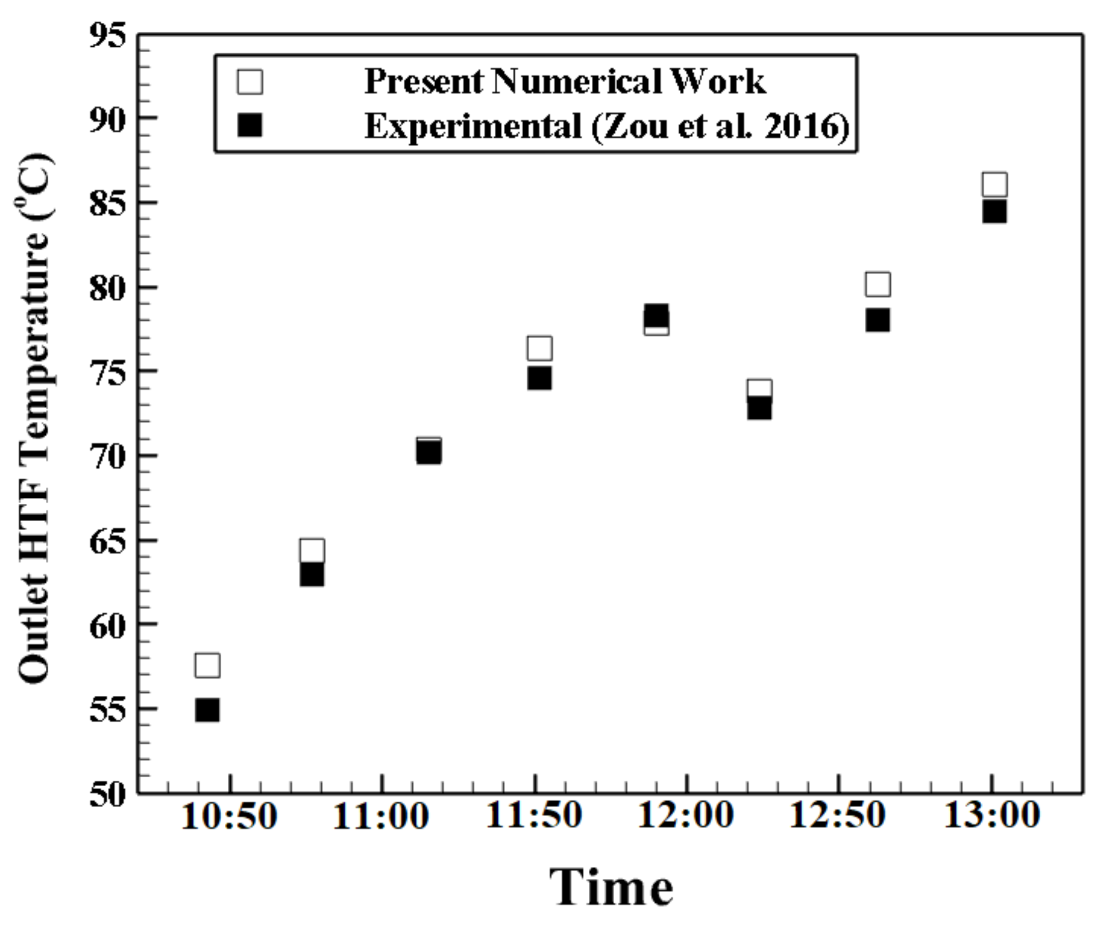
4.2. Validation Study

The Dittus-Boelter correlation [59] provides the Nusselt number as a function of the Re and Pr according to Equation (7):
Nu = 0.023 Re0.8 Pr0.4
Additionally, the Seban-Shimazaki correlation [59] (Equation (8)) is employed to compare with the simulation outcomes. A high correlation is suggested for PeD ≥ 100. The outcomes of the validation study are demonstrated in Figure 5. Therefore, the available work presents good accuracy. Additionally, to validate the present numerical model with the results of the performance of a real PTC system, the experimental results of Zou et al. [60] are used, and the comparison is presented in Figure 6. It can be concluded that present numerical method has good capacity for modeling the fluid and thermal characteristics in a PTC system. The uncertainty in measurement of the experimental parameters of the Zou et al. work [60] was as follows. The uncertainty in HTF velocity measurement was ± 0.05 m / s for HTF velocity up to 0.28   m / s and ± 0.2   m / s for HTF velocity between 0.28 and 0.32   m / s . The uncertainty of HTF temperature was ± 0.3 ° C in this study.
Nu = 5 + 0.025 PeD0.8

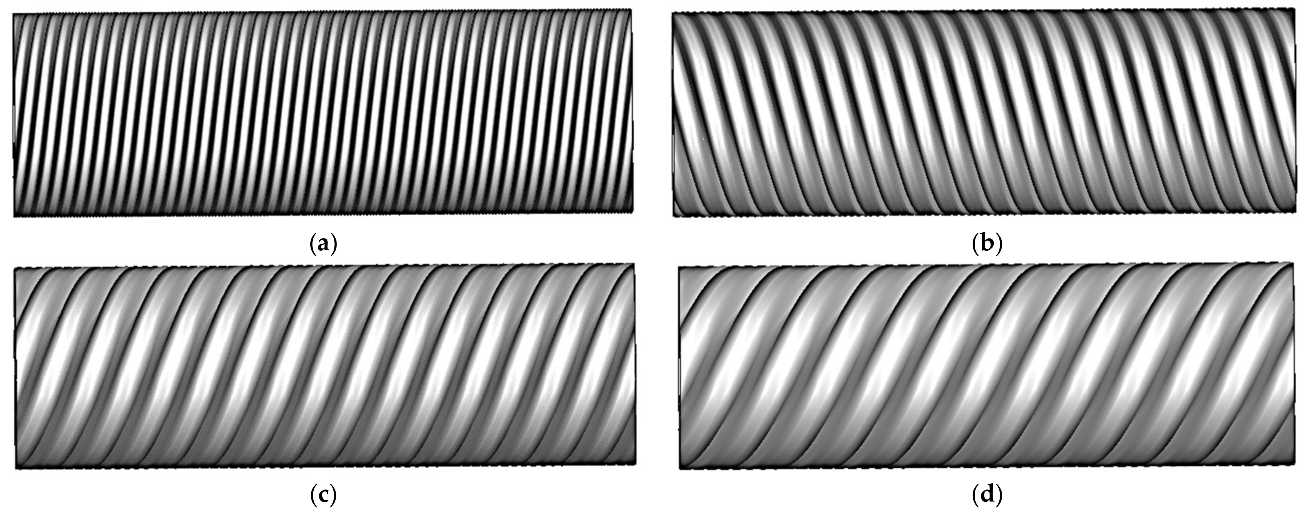
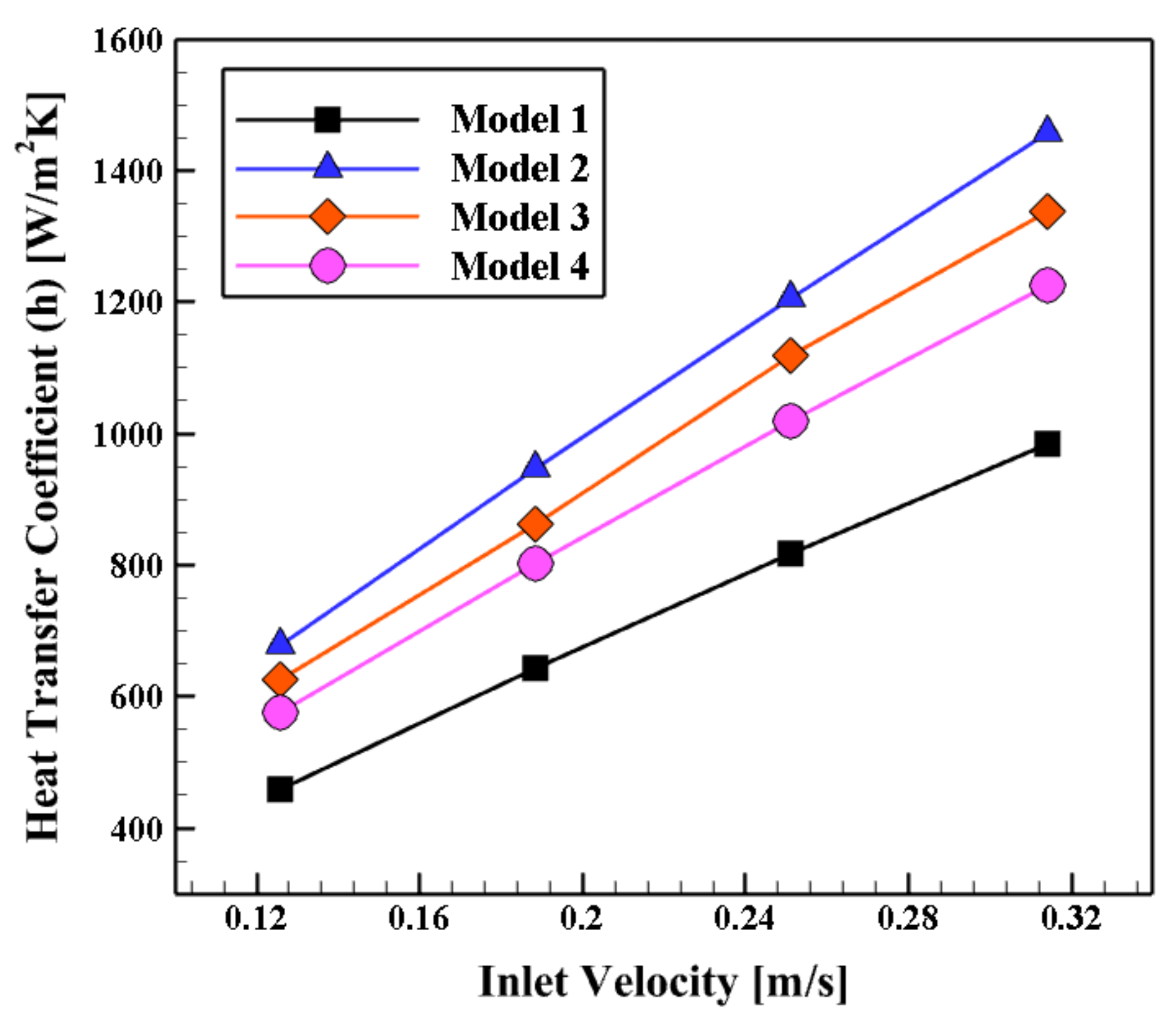
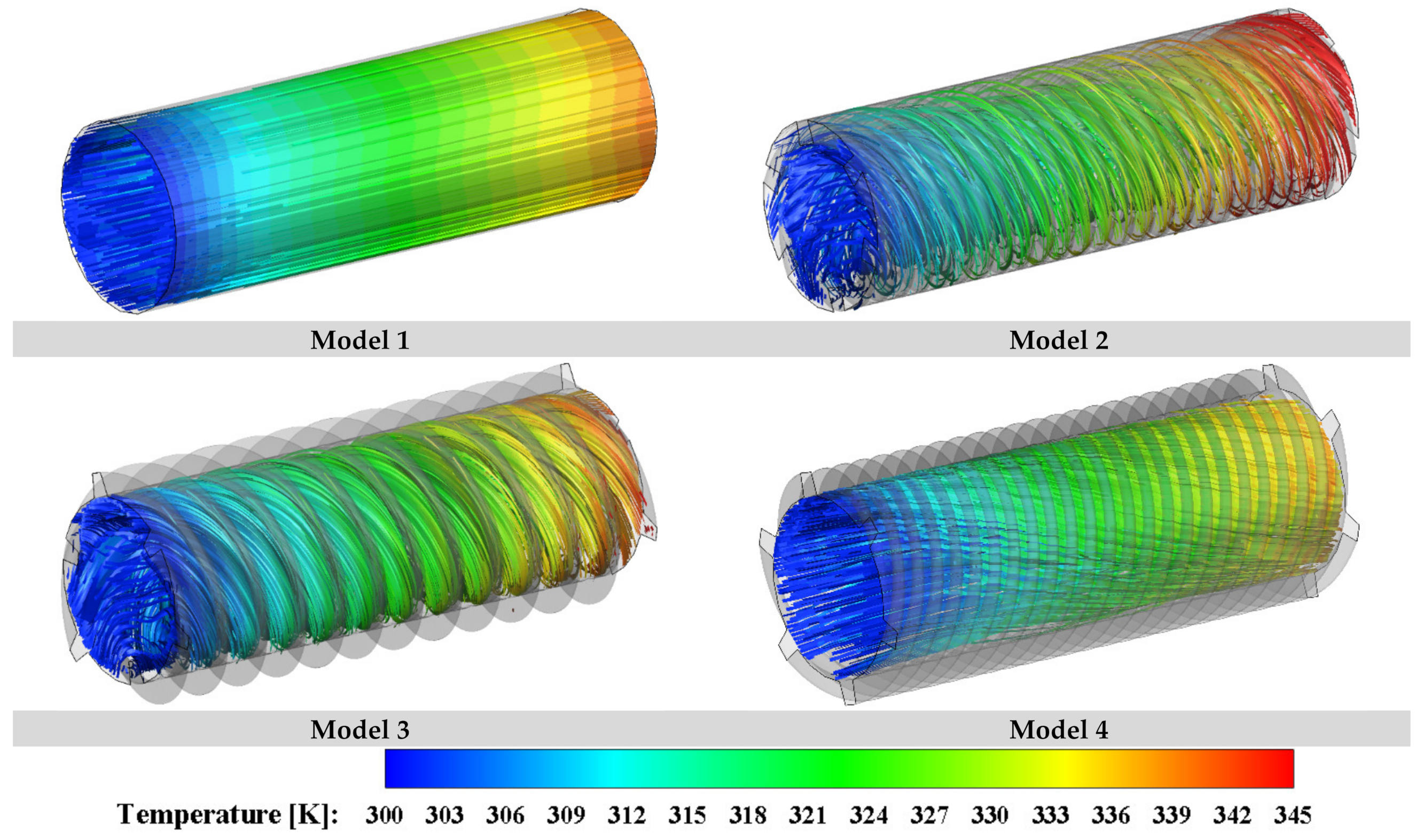
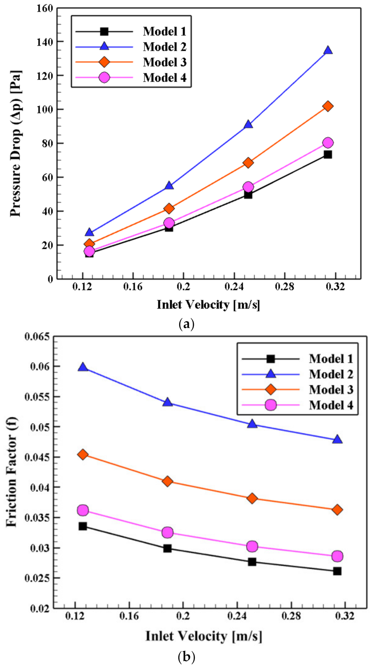
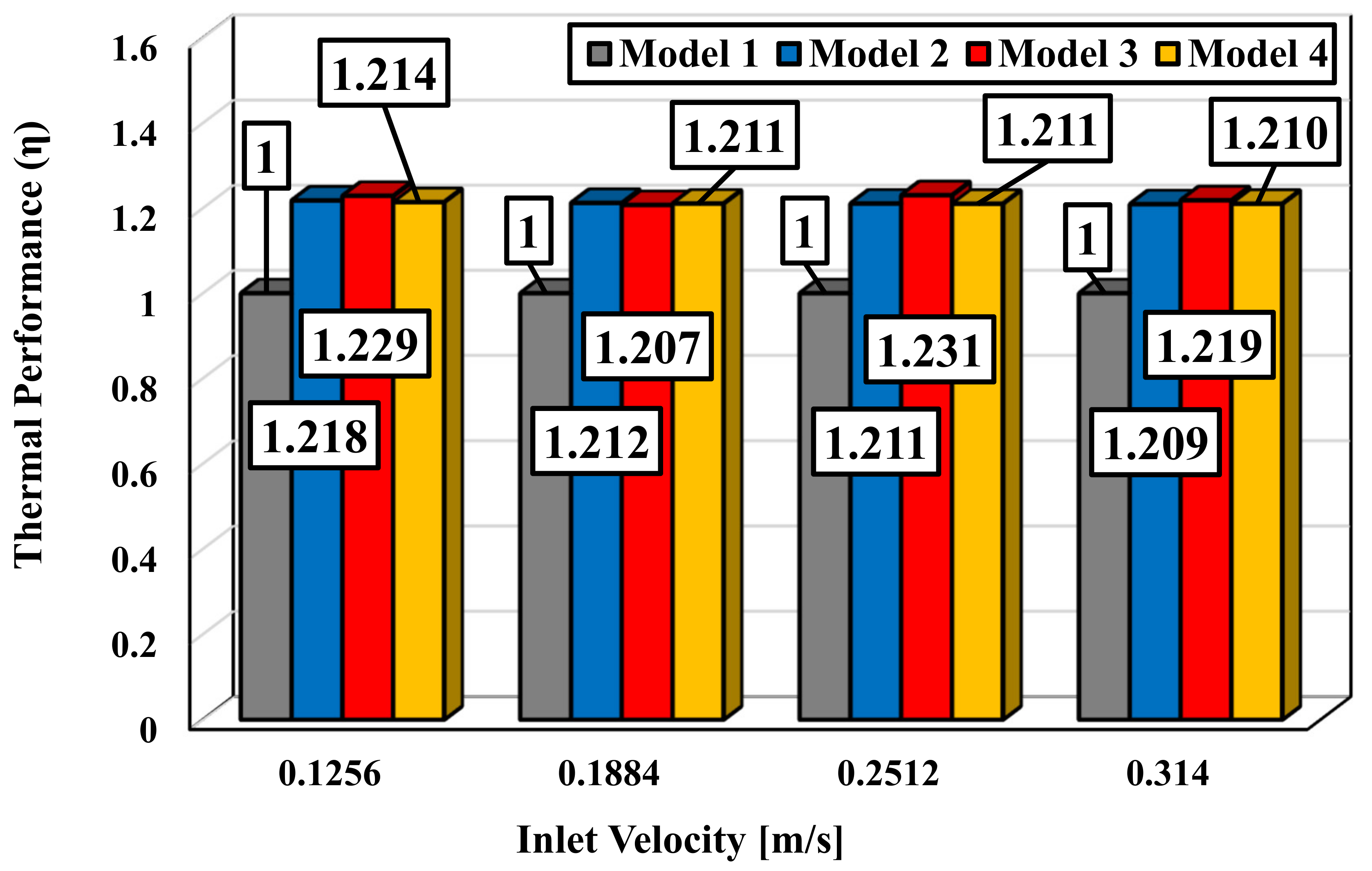
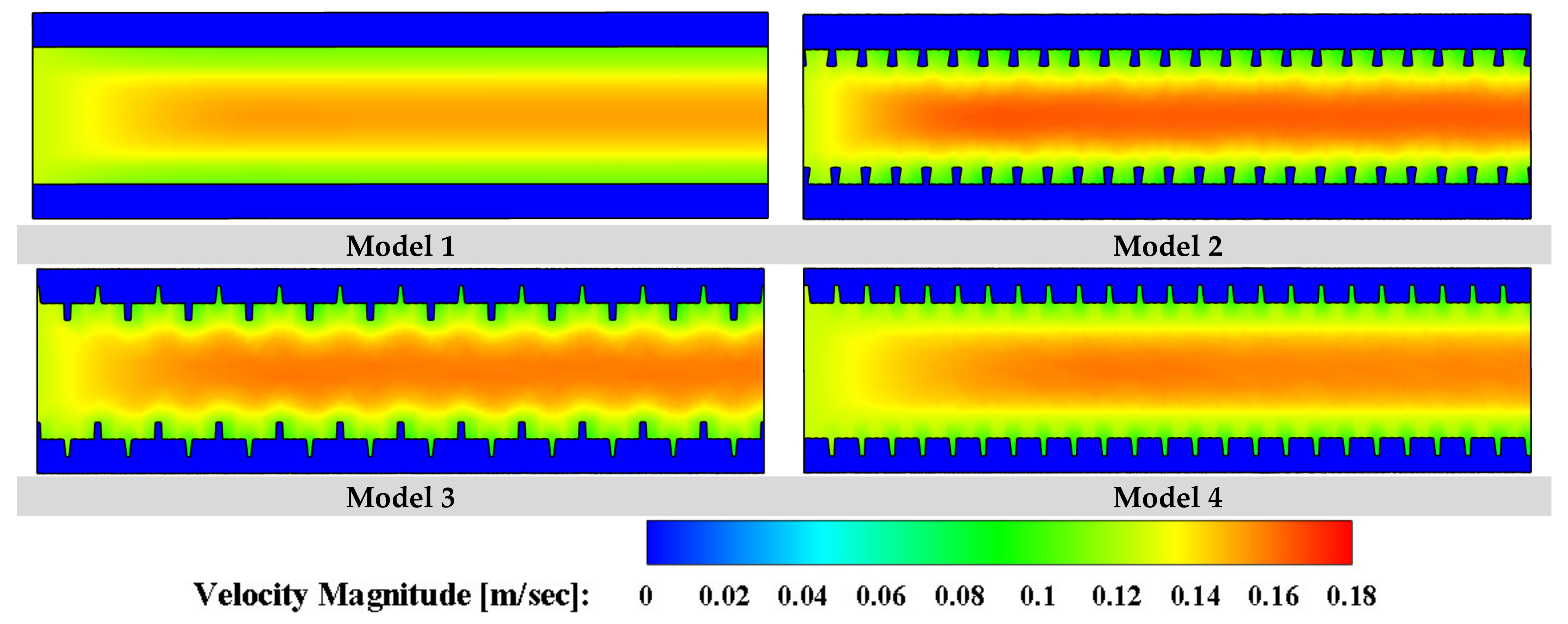
4.3. The Impact of the Schematic of the Proposed Collector’s Fins

In this section, the influence of the collector shape on thermal efficiency is investigated numerically. Three various models are considered, and the obtained results have been compared with the simple shaped collector. The considered models here are shown in Figure 2. The variation of heat transfer coefficient versus different inlet velocity for various models is illustrated in Figure 7. Hence, it can be concluded that firstly, all the proposed models show higher heat transfer coefficient more than the simple collector (Model 1). Secondly, it is depicted that among the studied models, the maximum heat transfer coefficient belongs to Model 2 in all studied inlet velocities. Additionally, the minimum heat transfer coefficient belongs to Model 4 in all considered inlet velocities.
To realize better the effect of geometry on the thermal performance of the proposed system, the streamline with the contour of temperature for all four studied models is shown in Figure 8. Hence, it can result that the schematic of the geometry and also the attendance of the inner axial helical fins have a significant impression on the rotation flow production and finally more heat transfer rate. Furthermore, contours show that Model 4 could enhance the heat transfer rate more than the other models. Additionally, all models depict better thermal performance in comparison with the collector equipped with simple channel (Model 1) because of the presence of swirl flows generated by the helical fins.
The variation of pressure drop and friction factor (f) versus various inlet velocities for various models are illustrated in Figure 9a,b, respectively. Figure 9a depicts that all models have more pressure drop compare to Model 1 (collector with simple channel, without helical fins) obviously because of presence of swirl flows. The maximum pressure drop belongs to Model 2 and the Model 4 shows lowest pressure drop among these four models. Additionally, as the inlet velocities rises, the pressure drop increases due to the effect of forced convection in the channel. This trend is the same for all models. Moreover, by increasing the inlet velocities, the differences between the studied models rises. This point could be important considering the pressure drop factor, as the differences between Model 4 and Model 1 (as base model) are very low.
Figure 9b shows that the trend of variation of fraction factor among the models is the same with pressure drop (Figure 9a). However, it should be focused that the variation of friction factor with inlet velocities is not the same with pressure drop, and they are exactly the opposite. By increasing the inlet velocity, the friction factor declines. According to Equation (5), the friction factor is directly related to the pressure drop; however, the squared velocity is placed at the denominator of the equation.
Contours of temperature at outlet for various models and P = 500 mm are presented in Figure 10. The impact of changing the schematic of the collector on temperature distribution in the outlet port and also the heat transfer rate is presented clearly in this figure. Accordingly, all models show better temperature distribution than the Model 1 (simple one, without fins).
The best parameter to comprehensively study the impact of efficient parameters on the performance of the proposed collector is thermal efficiency (η), which is calculated by Equation (6). In this Equation, the index 0 refers to the base collector (without fins). The variation of this parameter versus various inlet velocity for variant models are presented in Figure 11. Hence, it can be firstly concluded that all the models illustrate higher thermal performance than Model 1 (simple collector without fins), which means that the values of thermal performance are higher than unity. Furthermore, the highest and lowest thermal performance improvements (compared to Model 1) belong to the Model 3 by 23.1% (at Vinlet = 0.2512 m/s) and Model 3 by 20.7% (at Vinlet = 0.1884 m/s), respectively. Contours of velocity magnitude at surface X = 0 for various models at P = 500 mm and VInlet = 0.1256 m/s are illustrated in Figure 12. It can be realized that among the considered models in this section, Model 2 depicts higher velocity magnitude and consequently more swirl flows in the proposed collector, which leads to a higher heat transfer rate.

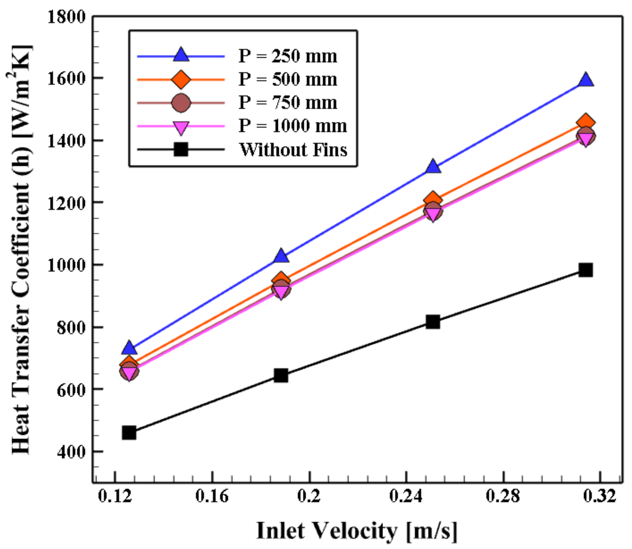
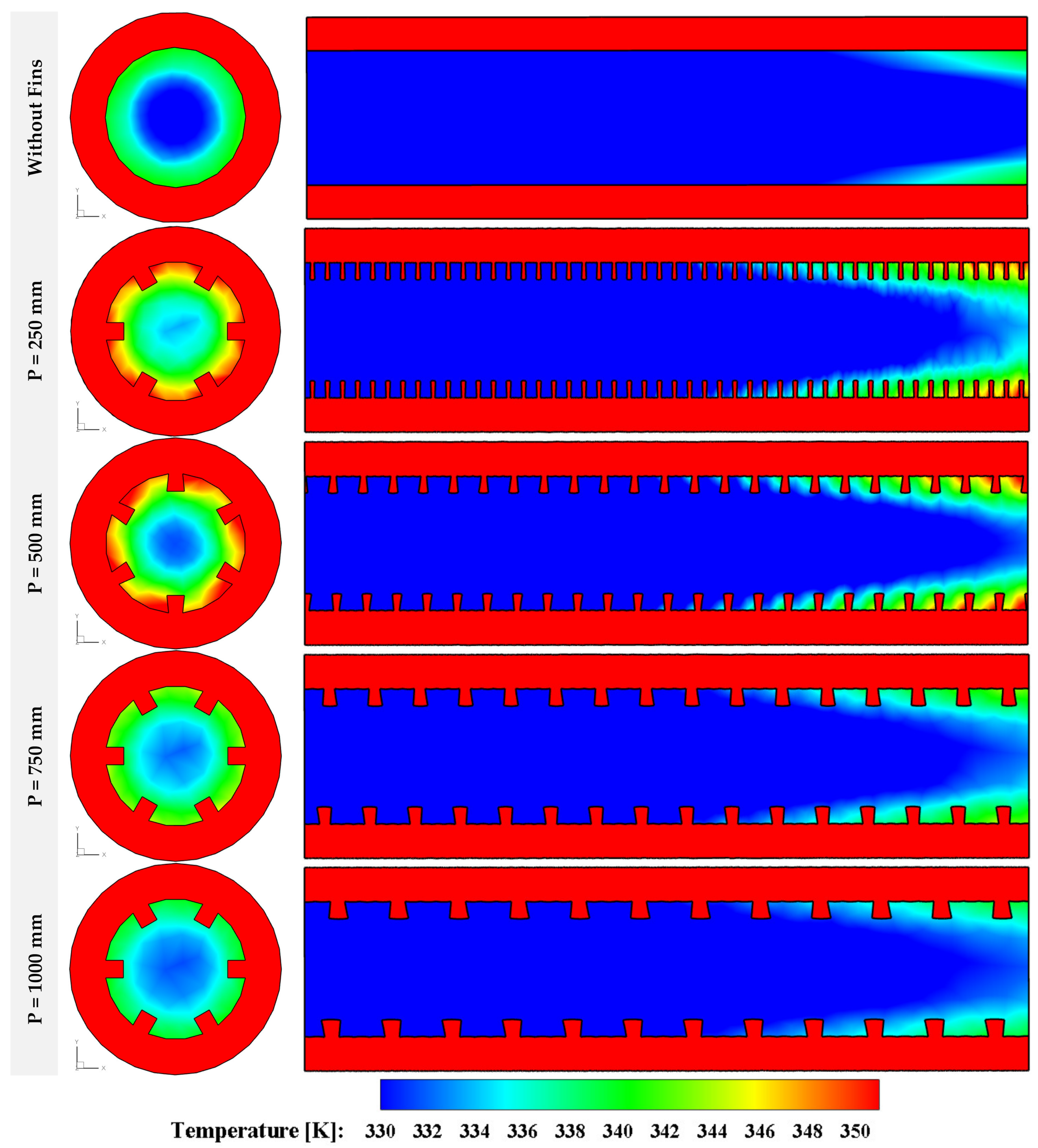
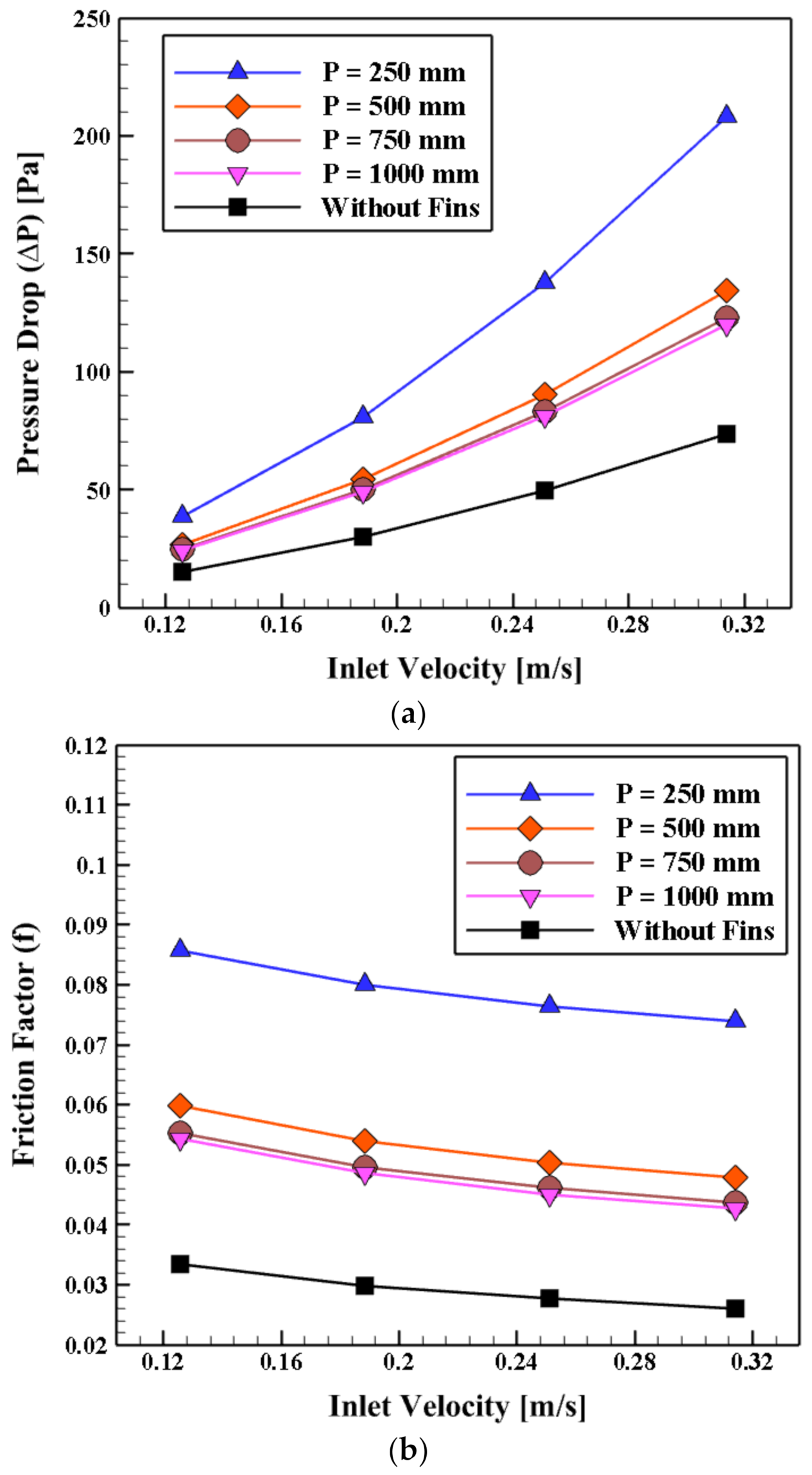
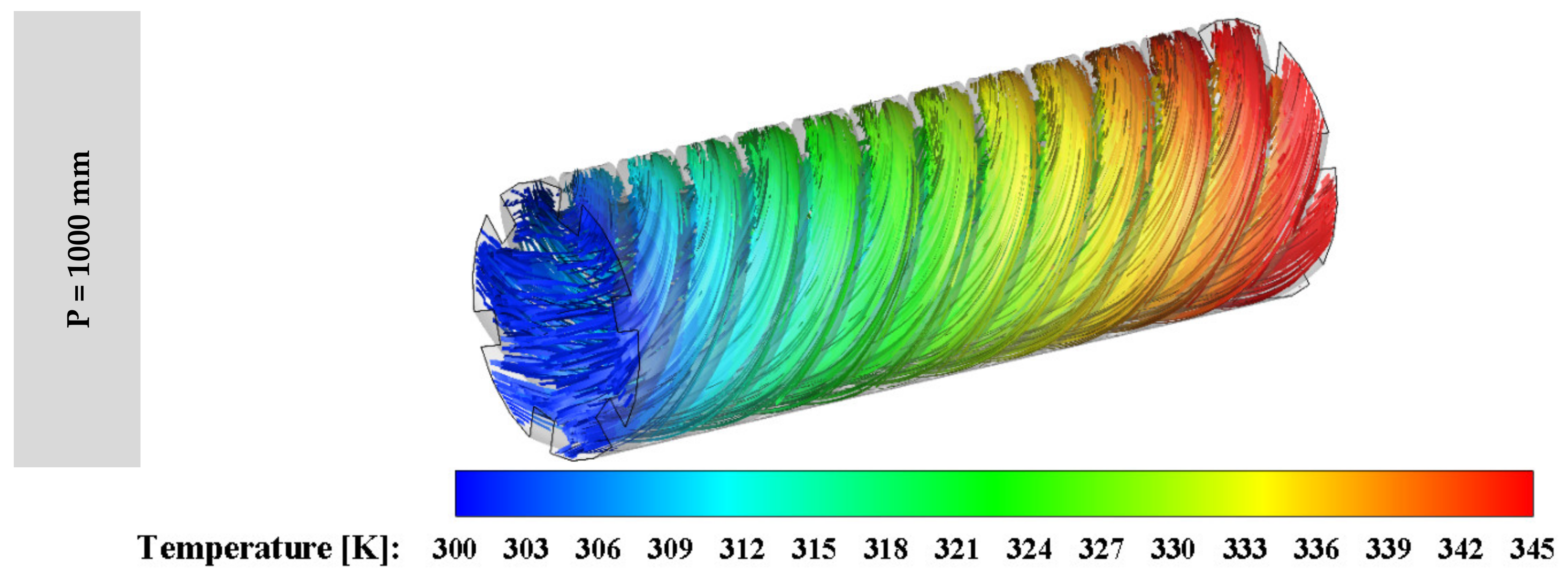
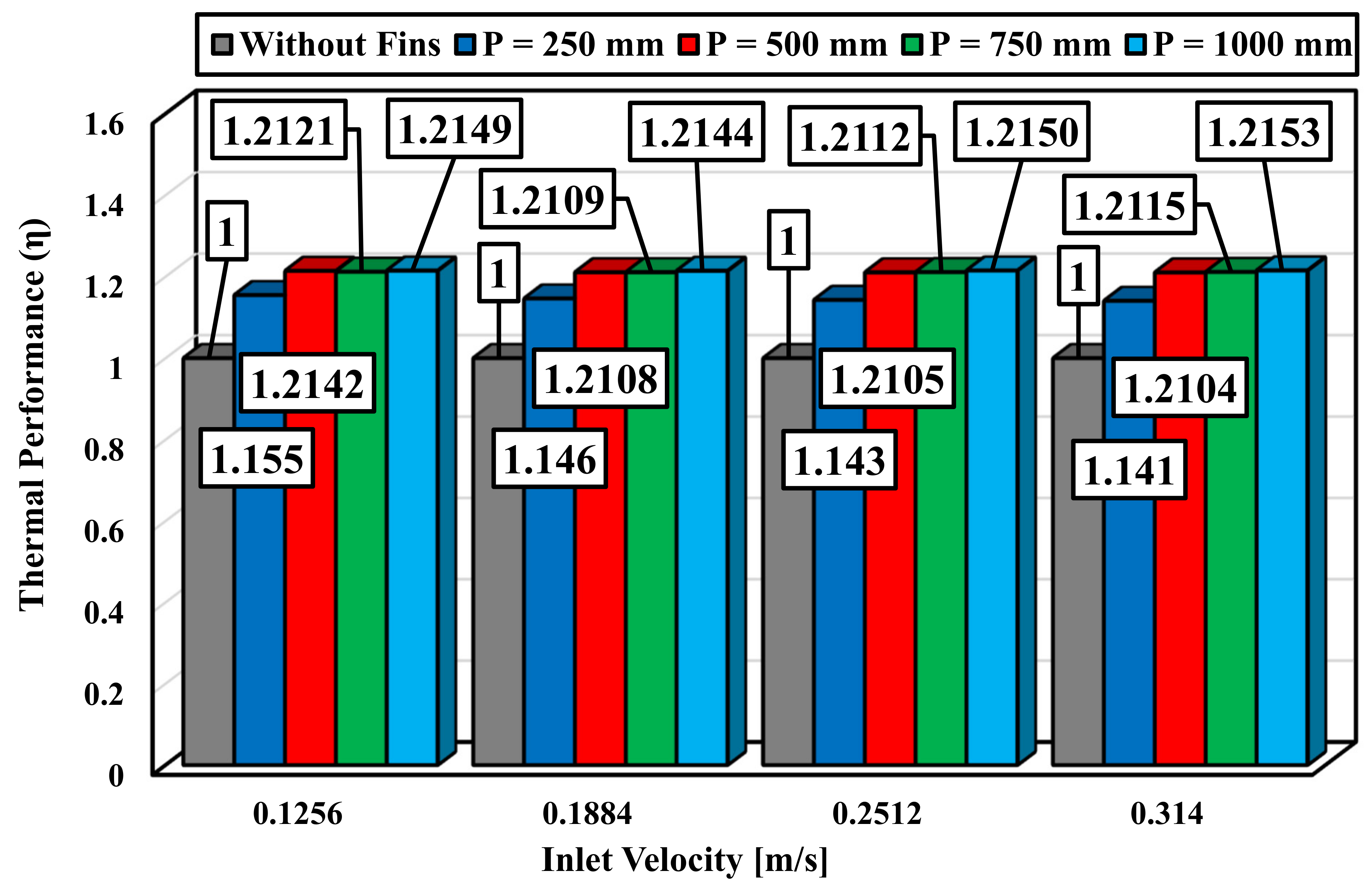
4.4. The Impact of the Inner Helical Fins Pitch (P)

In the second section, according to the obtained numerical results from the last section (Section 4.3), Model 2 (see Figure 2) is considered as the selected model here. Results from the last section showed that Model 2 has the maximum heat transfer coefficient with the highest pressure drop. Therefore, to study the impact of the inner helical fins pitch, this model is used. In this section, the impact of the inner helical fins pitch on the thermal efficiency of the system is evaluated numerically. Four various pitches of the inner helical fins including 250, 500, 750 and 1000 mm are considered, and the obtained outcomes are compared with the simple collector (without fins). The considered models here are shown in Figure 3. The variation of heat transfer coefficient versus different inlet velocity for various models is illustrated in Figure 13.
According to Figure 13, it can be concluded that firstly, all the proposed models show higher heat transfer coefficient more than the simple collector (without fins). Secondly, it is depicted that among the studied models, the unmost heat transfer coefficient belongs to case with P = 250 mm in all studied inlet velocities. Additionally, the least heat transfer coefficient belongs to the case with P = 1000 mm in all considered inlet velocities. To realize better the impact of the pitch of inner helical fins on the thermal performance of the proposed collector, the contour of temperature at outlet and a slice in the middle of the computational domain (X = 0) for all cases are shown in Figure 14. It can be obviously seen that higher temperature in the proposed collector is achieved at lower pitch of the inner helical fins.
The variations of pressure drop and friction factor (f) versus various inlet velocities for various models are illustrated in Figure 15a,b, respectively. Figure 15a depicts that all models have higher pressure drop compared to the case without helical fins obviously because of the presence of swirl flows. The greatest pressure drop belongs to the case with P = 250 mm, and the case with P = 1000 mm shows the lowest pressure drop among the investigated models. Additionally, as the inlet velocities rise, the pressure drop increases due to the effect of forced convection in the channel. This trend is the same for all models. Moreover, by increasing the inlet velocities, the differences between the studied models rise. This point could be important considering the pressure drop factor, as the differences between the cases with P = 500, 750 and 1000 mm are very low.
Figure 15b shows that the trend of variation of fraction factor among the models is the same with pressure drop (Figure 15a). On the other hand, as same as Figure 15a, the highest and lowest friction factor belong to the cases with P = 250 mm and P = 1000 mm, respectively. However, it should be focused that the variation of friction factor with inlet velocities is not the same with pressure drop and they are exactly the opposite. By increasing the inlet velocity, the friction factor declines. According to Equation (5), the friction factor is directly related to pressure drop; however, the squared velocity is placed at the denominator of the equation.
The streamline with the contour of temperature for various models are presented in Figure 16. The impact of changing the schematic of the collector on temperature distribution in the outlet port and also the heat transfer rate is presented clearly in this figure. Accordingly, all models show better temperature distribution than the case without fins.
The best parameter to study comprehensively the impact of efficient parameters on the performance of the proposed collector is thermal efficiency (η), which is calculated by Equation (6). The variation of this parameter is presented in Figure 17. Therefore, it can be concluded firstly that all the models illustrate higher thermal performance than the case without fins, which means that the values of thermal performance are higher than unity. Furthermore, the greatest and smallest thermal performance improvement (compare to the case without fins) belong to the case with P = 1000 mm by 21.53% and the case with P = 250 mm by 14.1% for the latest velocity, respectively.

5. Conclusions and Future Scope

In the present work, a PTC collector with inner helical axial fins as a swirl generator or turbulator is considered and analyzed. This work consists of two parts. In the first part, four various geometries of the collector are appraised. In the second part, the selected schematic of the collector from the first sector is selected and four various pitches of inner helical fins including 250, 500, 750 and 1000 mm are studied. Results presented that the thermal performance improvement by 23.1% could be achieved by using one of the proposed innovative parabolic trough solar collector compare to the simple one. Additionally, the utmost and least thermal performance improvement (compare to the case without fins) belong to the case with P = 1000 mm by 21.53% (at Vinlet = 0.314 m/s) and the case with P = 250 mm by 14.1% (at Vinlet = 0.314 m/s), respectively.
Although present work has presented new insight into the flow and thermal characteristics of a parabolic trough solar collector combining innovative inner helical axial fins as a swirl generator, additional research is required to determine the capability of this design in more realistic engineering situations by the development of an experimental prototype.

Author Contributions

Investigation, Software, Validation, Writing—original draft, M.Z.; Formal analysis, Methodology, Validation, Writing—review & editing, S.S.M.A.; Supervision, Writing—review & editing, S.S.; Funding acquisition, Writing—review & editing, M.S.P. All authors have read and agreed to the published version of the manuscript.

Funding

This research received no external funding.

Institutional Review Board Statement

Not applicable.

Informed Consent Statement

Not applicable.

Data Availability Statement

Data available on request due to restrictions eg privacy or ethical.

Conflicts of Interest

The authors declare no conflict of interest.

Expects Data

Data available on request from the authors: The data that support the findings of this study are available from the corresponding author upon reasonable request.

Nomenclature

AArea, m2Greek and Symbols
CPSpecific heat capacity, [kJ/(kg. K)]ρDensity, kg/m3
D1Diameter of inner the tube, [m]μViscosity, kg/m·s
D2Diameter of outer the tube, [m] τ   = Stress tensor
dDiameter, [m]σTurbulent Prandtl number
fDarcy friction factor, [nd] η Thermal performance, [nd]
GbGeneration of turbulence kinetic energy due to buoyancy, [J/kg]αHelical angle of the Fins, [degree]
GkGeneration of turbulence kinetic energy due to the mean velocity gradients, [J/kg]kturbulent kinetic energy per unit mass, [J/kg]
gGravity, [m/s2]εenergy dissipation rate per unit mass, [W/kg]
HHeight of the Fins, [m]Dimensionless Parameter
hHeat transfer coefficient, [W/(m2·K)]PePéclet number, Pe =   Re .   Pr , [nd]
kThermal conductivity, [W/(m·K)]PrPrandtl number, Pr = c p µ k , [nd]
LLength of the tube, [m]NuNusselt number, Nu = h d k , [nd]
MtTurbulent Mach number, [nd]ReReynolds number, Re = P u d µ , [nd]
PHelix pitch of the Fins, [m]Index
pPressure, [Pa]0Reference
ShHeat generation, [J/m3]effEffective
SmMass generation, [kg/m3]hHydraulic
TTemperature, [°C]mAverage
tTime, [s]PRPerformance Ratio
thThickness of the Fins, [m]refreference
vVelocity, [m·s−1]tturbulence
Abbreviation
PTCsParabolic Trough Collectors
ExpExperimental
NumNumerical

References

  1. Berger, S.A.; Talbot, L.; Yao, L.S. Flow in curved pipes. Annu. Rev. Fluid Mech. 1983, 15, 461–512. [Google Scholar] [CrossRef]
  2. Sheikholeslami, M.; Gorji-Bandpy, M.; Ganji, D.D. Review of heat transfer enhancement methods: Focus on passive methods using swirl flow devices. Renew. Sustain. Energy Rev. 2015, 49, 444–469. [Google Scholar] [CrossRef]
  3. Esfe, M.H.; Saedodin, S.; Wongwises, S.; Toghraie, D. An experimental study on the effect of diameter on thermal conductivity and dynamic viscosity of Fe/water nanofluids. J. Therm. Anal. Calorim. 2015, 119, 1817–1824. [Google Scholar] [CrossRef]
  4. Zaboli, M.; Ajarostaghi, S.S.; Noorbakhsh, M.; Delavar, M.A. Effects of geometrical and operational parameters on heat transfer and fluid flow of three various water based nanofluids in a shell and coil tube heat exchanger. SN Appl. Sci. 2019, 1, 1387. [Google Scholar] [CrossRef] [Green Version]
  5. Kim, K.; Lee, K.S. Frosting and defrosting characteristics of surface-treated louvered-fin heat exchangers: Effects of fin pitch and experimental conditions. Int. J. Heat Mass Transf. 2013, 60, 505–511. [Google Scholar] [CrossRef]
  6. Gao, D.; Wang, Y. Generating high-purity orbital angular momentum vortex waves from Cassegrain meta-mirrors. Eur. Phys. J. Plus 2020, 135. [Google Scholar] [CrossRef]
  7. Hobbi, A.; Siddiqui, K. Experimental study on the effect of heat transfer enhancement devices in flat-plate solar collectors. Int. J. Heat Mass Transf. 2009, 52, 4650–4658. [Google Scholar] [CrossRef]
  8. Nuntaphan, A.; Vithayasai, S.; Vorayos, N.; Vorayos, N.; Kiatsiriroat, T. Use of oscillating heat pipe technique as extended surface in wire-on-tube heat exchanger for heat transfer enhancement. Int. Commun. Heat Mass Transf. 2010, 37, 287–292. [Google Scholar] [CrossRef]
  9. Dizaji, H.S.; Jafarmadar, S.; Asaadi, S. Experimental exergy analysis for shell and tube heat exchanger made of corrugated shell and corrugated tube. Exp. Therm. Fluid Sci. 2017, 81, 475–481. [Google Scholar] [CrossRef]
  10. Tang, L.H.; Zeng, M.; Wang, Q.W. Experimental and numerical investigation on air-side performance of fin-and-tube heat exchangers with various fin patterns. Exp. Therm. Fluid Sci. 2009, 33, 818–827. [Google Scholar] [CrossRef]
  11. Azari, M.; Sadeghi, A.; Chakraborty, S. Electroosmotic flow and heat transfer in a heterogeneous circular microchannel. Appl. Math. Model. 2020, 87, 640–654. [Google Scholar] [CrossRef]
  12. Darzi, A.A.R.; Farhadi, M.; Sedighi, K. Experimental investigation of convective heat transfer and friction factor of Al2O3/water nanofluid in helically corrugated tube. Exp. Therm. Fluid Sci. 2014, 57, 188–199. [Google Scholar] [CrossRef]
  13. Du, T.; Chen, Q.; Du, W.; Cheng, L. Performance of continuous helical baffled heat exchanger with varying elliptical tube layouts. Int. J. Heat Mass Transf. 2019, 133, 1165–1175. [Google Scholar] [CrossRef]
  14. Bahiraei, M.; Mazaheri, N.; Rizehvandi, A. Application of a hybrid nanofluid containing graphene nanoplatelet-platinum composite powder in a triple-tube heat exchanger equipped with inserted ribs. Appl. Therm. Eng. 2019, 149, 588–601. [Google Scholar] [CrossRef]
  15. Abolarin, S.M.; Everts, M.; Meyer, J.P. Heat transfer and pressure drop characteristics of alternating clockwise and counter clockwise twisted tape inserts in the transitional flow regime. Int. J. Heat Mass Transf. 2019, 133, 203–217. [Google Scholar] [CrossRef] [Green Version]
  16. Zhang, Y.; Zhou, F.; Kang, J. Flow and heat transfer in drag-reducing polymer solution flow through the corrugated tube and circular tube. Appl. Therm. Eng. 2020, 115185. [Google Scholar] [CrossRef]
  17. Rashidi, S.; Hormozi, F.; Sundén, B.; Mahian, O. Energy saving in thermal energy systems using dimpled surface technology—A review on mechanisms and applications. Appl. Energy 2019, 250, 1491–1547. [Google Scholar] [CrossRef]
  18. Kareem, Z.S.; Abdullah, S.; Lazim, T.M.; Jaafar, M.M.; Wahid, A.F. Heat transfer enhancement in three-start spirally corrugated tube: Experimental and numerical study. Chem. Eng. Sci. 2015, 134, 746–757. [Google Scholar] [CrossRef]
  19. Lu, G.; Zhou, G. Numerical simulation on performances of plane and curved winglet type vortex generator pairs with punched holes. Int. J. Heat Mass Transf. 2016, 102, 679–690. [Google Scholar] [CrossRef]
  20. Mashoofi, N.; Pesteei, S.M.; Moosavi, A.; Dizaji, H.S. Fabrication method and thermal-frictional behavior of a tube-in-tube helically coiled heat exchanger which contains turbulator. Appl. Therm. Eng. 2017, 111, 1008–1015. [Google Scholar] [CrossRef]
  21. Aghaei, A.; Sheikhzadeh, G.A.; Goodarzi, M.; Hasani, H.; Damirchi, H.; Afrand, M. Effect of horizontal and vertical elliptic baffles inside an enclosure on the mixed convection of a MWCNTs-water nanofluid and its entropy generation. Eur. Phys. J. Plus 2018, 133, 486. [Google Scholar] [CrossRef]
  22. Noorbakhsh, M.; Zaboli, M.; Ajarostaghi, S.S. Numerical evaluation of the effect of using twisted tapes as turbulator with various geometries in both sides of a double-pipe heat exchanger. J. Therm. Anal. Calorim. 2020, 140, 1341–1353. [Google Scholar] [CrossRef]
  23. Kwon, B.; Liebenberg, L.; Jacobi, A.M.; King, W.P. Heat transfer enhancement of internal laminar flows using additively manufactured static mixers. Int. J. Heat Mass Transf. 2019, 137, 292–300. [Google Scholar] [CrossRef]
  24. Ho, C.J.; Hsieh, Y.J.; Rashidi, S.; Orooji, Y.; Yan, W.M. Thermal-hydraulic analysis for alumina/water nanofluid inside a mini-channel heat sink with latent heat cooling ceiling—An experimental study. Int. Commun. Heat Mass Transf. 2020, 112, 104477. [Google Scholar] [CrossRef]
  25. Liu, H.L.; Qi, D.H.; Shao, X.D.; Wang, W.D. An experimental and numerical investigation of heat transfer enhancement in annular microchannel heat sinks. Int. J. Therm. Sci. 2019, 142, 106–120. [Google Scholar] [CrossRef]
  26. Ramalingam, S.; Dhairiyasamy, R.; Govindasamy, M. Assessment of heat transfer characteristics and system physiognomies using HYBRID nanofluids in an automotive radiator. Chem. Eng. Process. Process. Intensif. 2020, 107886. [Google Scholar] [CrossRef]
  27. Qi, C.; Fan, F.; Pan, Y.; Liu, M.; Yan, Y. Effects of turbulator with round hole on the thermo-hydraulic performance of nanofluids in a triangle tube. Int. J. Heat Mass Transf. 2020, 146, 118897. [Google Scholar] [CrossRef]
  28. Nakhchi, M.E.; Esfahani, J.A. Numerical investigation of heat transfer enhancement inside heat exchanger tubes fitted with perforated hollow cylinders. Int. J. Therm. Sci. 2020, 147, 106153. [Google Scholar] [CrossRef]
  29. Rahbarshahlan, S.; Esmaeilzadeh, E.; Khosroshahi, A.R.; Bakhshayesh, A.G. Numerical simulation of fluid flow and heat transfer in microchannels with patterns of hydrophobic/hydrophilic walls. Eur. Phys. J. Plus 2020, 135, 157. [Google Scholar] [CrossRef]
  30. Jamesahar, E.; Sabour, M.; Shahabadi, M.; Mehryan, S.A.; Ghalambaz, M. Mixed convection heat transfer by nanofluids in a cavity with two oscillating flexible fins: A fluid-structure interaction approach. Appl. Math. Model. 2020, 82, 72–90. [Google Scholar] [CrossRef]
  31. Benabderrahmane, A.; Benazza, A.; Hussein, A.K. Heat transfer enhancement analysis of tube receiver for parabolic trough solar collector with central corrugated insert. J. Heat Transf. 2020, 142. [Google Scholar] [CrossRef]
  32. Akbarzadeh, S.; Valipour, M.S. Experimental study on the heat transfer enhancement in helically corrugated tubes under the non-uniform heat flux. J. Therm. Anal. Calorim. 2020. [Google Scholar] [CrossRef]
  33. Chakraborty, O.; Das, B.; Gupta, R.; Debbarma, S. Heat transfer enhancement analysis of parabolic trough collector with straight and helical absorber tube. Therm. Sci. Eng. Prog. 2020, 20, 100718. [Google Scholar] [CrossRef]
  34. Amani, K.; Ebrahimpour, M.; Akbarzadeh, S.; Valipour, M.S. The utilization of conical strip inserts in a parabolic trough collector. J. Therm. Anal. Calorim. 2020. [Google Scholar] [CrossRef]
  35. Khan, M.S.; Yan, M.; Ali, H.M.; Amber, K.P.; Bashir, M.A.; Akbar, B.; Javed, S. Comparative performance assessment of different absorber tube geometries for parabolic trough solar collector using nanofluid. J. Therm. Anal. Calorim. 2020, 142, 2227–2241. [Google Scholar] [CrossRef]
  36. Saedodin, S.; Zaboli, M.; Ajarostaghi, S.S.M. Hydrothermal analysis of heat transfer and thermal performance characteristics in a parabolic trough solar collector with Turbulence-Inducing elements. Sustain. Energy Technol. Assess. 2021, 46, 101266. [Google Scholar] [CrossRef]
  37. Vasanthi, P.; Reddy, G.J.C. Experimental Investigations on Heat Transfer and Friction Factor of Hybrid Nanofliud Equiped with Angular Twisted Strip Inserts in a Parabolic Trough Solar Collector under Turbulent Flow. Int. J. Innov. Sci. Eng. Technol. 2021, 8, 315–336. [Google Scholar]
  38. Chakraborty, O.; Roy, S.; Das, B.; Gupta, R. Effects of helical absorber tube on the energy and exergy analysis of parabolic solar trough collector—A computational analysis. Sustain. Energy Technol. Assess. 2021, 44, 101083. [Google Scholar] [CrossRef]
  39. Akbarzadeh, S.; Valipour, M.S. The thermo-hydraulic performance of a parabolic trough collector with helically corrugated tube. Sustain. Energy Technol. Assess. 2021, 44, 101013. [Google Scholar] [CrossRef]
  40. Peng, H.; Li, M.; Hu, F.; Feng, S. Performance analysis of absorber tube in parabolic trough solar collector inserted with semi-annular and fin shape metal foam hybrid structure. Case Stud. Therm. Eng. 2021, 101112. [Google Scholar] [CrossRef]
  41. Sheikholeslami, M.; Farshad, S.A. Nanofluid flow inside a solar collector utilizing twisted tape considering exergy and entropy analysis. Renew. Energy 2019, 141, 246–258. [Google Scholar] [CrossRef]
  42. Moghaddaszadeh, N.; Esfahani, J.A.; Mahian, O. Performance enhancement of heat exchangers using eccentric tape inserts and nanofluids. J. Therm. Anal. Calorim. 2019, 137, 865–877. [Google Scholar] [CrossRef]
  43. Ghasemi, S.E.; Ranjbar, A.A. Thermal performance analysis of solar parabolic trough collector using nanofluid as working fluid: A CFD modelling study. J. Mol. Liq. 2016, 222, 159–166. [Google Scholar] [CrossRef]
  44. Reddy, K.S.; Ravi, K.K.; Satyanarayana, G.V. Numerical Investigation of Energy-Efficient Receiver for Solar Parabolic Trough Concentrator. Heat Transf. Eng. 2008, 29, 961–972. [Google Scholar] [CrossRef]
  45. He, W.; Toghraie, D.; Lotfipour, A.; Pourfattah, F.; Karimipour, A.; Afrand, M. Effect of twisted-tape inserts and nanofluid on flow field and heat transfer characteristics in a tube. Int. Commun. Heat Mass Transf. 2020. [Google Scholar] [CrossRef]
  46. Eiamsa-Ard, S.; Thianpong, C.; Promvonge, P. Experimental investigation of heat transfer and flow friction in a circular tube fitted with regularly spaced twisted tape elements. Int. Commun. Heat Mass Transf. 2006, 33, 1225–1233. [Google Scholar] [CrossRef]
  47. Fluent, A.N. 18.2, Theory Guide; ANSYS Inc.: Canonsburg, PA, USA, 2017. [Google Scholar]
  48. Bejan, A. Convection Heat Transfer; John Wiley & Sons: Hoboken, NJ, USA, 2013. [Google Scholar]
  49. Zaboli, M.; Nourbakhsh, M.; Ajarostaghi, S.S. Numerical evaluation of the heat transfer and fluid flow in a corrugated coil tube with lobe-shaped cross-section and two types of spiral twisted tape as swirl generator. J. Therm. Anal. Calorim. 2020. [Google Scholar] [CrossRef]
  50. Saedodin, S.; Zaboli, M.; Rostamian, S.H. Effect of twisted turbulator and various metal oxide nanofluids on the thermal performance of a straight tube: Numerical study based on experimental data. Chem. Eng. Process. Process. Intensif. 2020, 158, 108106. [Google Scholar] [CrossRef]
  51. Baragh, S.; Shokouhmand, H.; Ajarostaghi, S.S.M.; Nikian, M. An experimental investigation on forced convection heat transfer of single-phase flow in a channel with different arrangements of porous media. Int. J. Therm. Sci. 2018, 134, 370–379. [Google Scholar] [CrossRef]
  52. Baragh, S.; Shokouhmand, H.; Ajarostaghi, S.S.M. Experiments on mist flow and heat transfer in a tube fitted with porous media. Int. J. Therm. Sci. 2019, 137, 388–398. [Google Scholar] [CrossRef]
  53. Karouei, S.H.H.; Ajarostaghi, S.S.M.; Gorji-Bandpy, M.; Fard, S.R.H. Laminar heat transfer and fluid flow of two various hybrid nanofluids in a helical double-pipe heat exchanger equipped with an innovative curved conical turbulator. J. Therm. Anal. Calorim. 2020. [Google Scholar] [CrossRef]
  54. Hamedani, F.A.; Ajarostaghi, S.S.M.; Hosseini, S.A. Numerical evaluation of the effect of geometrical and operational parameters on thermal performance of nanofluid flow in convergent-divergent tube. J. Therm. Anal. Calorim. 2019. [Google Scholar] [CrossRef]
  55. Moghadam, H.K.; Ajarostaghi, S.S.M.; Poncet, S. Extensive numerical analysis of the thermal performance of a corrugated tube with coiled wire. J. Therm. Anal. Calorim. 2019. [Google Scholar] [CrossRef]
  56. Outokesh, M.; Ajarostaghi, S.S.M.; Bozorgzadeh, A.; Sedighi, K. Numerical evaluation of the effect of utilizing twisted tape with curved profile as a turbulator on heat transfer enhancement in a pipe. J. Therm. Anal. Calorim. 2020, 140, 1537–1553. [Google Scholar] [CrossRef]
  57. Olfian, H.; Sheshpoli, A.Z.; Ajarostaghi, S.S.M. Numerical evaluation of the thermal performance of a solar air heater equipped with two different types of baffles. Heat Transf. 2020, 49, 1149–1169. [Google Scholar] [CrossRef]
  58. Ajarostaghi, S.S.M.; Delavar, M.A.; Poncet, S. Thermal mixing, cooling and entropy generation in a micromixer with a porous zone by the lattice Boltzmann method. J. Therm. Anal. Calorim. 2020, 140, 1321–1339. [Google Scholar] [CrossRef]
  59. Bergman, T.L.; Lavine, A.S.; Incropera, F.P.; DeWitt, D.P. Introduction to Heat Transfer; John Wiley & Sons: Hoboken, NJ, USA, 1990. [Google Scholar]
  60. Zou, B.; Dong, J.; Yao, Y.; Jiang, Y. An experimental investigation on a small-sized parabolic trough solar collector for water heating in cold areas. Appl. Energy 2016, 163, 396–407. [Google Scholar] [CrossRef]
Figure 1. (a) A schematic of the PTC structure, (b) the schematic of the considered pipe and the inner helical axial fins, and (c) the geometrical parameters.
Applsci 11 07423 g001
Figure 2. The schematics of the evaluated geometries in the first section of present work.
Applsci 11 07423 g002
Figure 3. The schematics of the evaluated geometries in the second section of present work. (a) P = 250 mm, (b) P = 500 mm, (c) P = 750 mm and (d) P = 1000 mm.
Applsci 11 07423 g003
Figure 4. Considered grid for proposed geometry as PTC.
Applsci 11 07423 g004
Figure 5. Validation betwixt the available simulation and (a) Dittus–Boelter correlation [41]; (b) Seban–Shimazaki correlation [59].
Applsci 11 07423 g005
Figure 6. Results of the validation analysis between the present numerical work and experimental work of Zou et al. [60].
Applsci 11 07423 g006
Figure 7. Heat transfer coefficient variation with the inlet velocity for various models at P = 500 mm.
Applsci 11 07423 g007
Figure 8. The streamline with contour of temperature for various models at P = 500 mm.
Applsci 11 07423 g008
Figure 9. (a) Pressure drop and (b) friction factor variation with the inlet velocity for various models at P = 500 mm.
Applsci 11 07423 g009
Figure 10. Contours of temperature at outlet and a slice (X = 0) for various models at P = 500 mm and VInlet = 0.1256 m/s.
Applsci 11 07423 g010
Figure 11. The thermal performance (η) versus inlet velocity for various models.
Applsci 11 07423 g011
Figure 12. Contours of velocity magnitude at surface X = 0 for various models at P = 500 mm and VInlet = 0.1256 m/s.
Applsci 11 07423 g012
Figure 13. Heat transfer coefficient variation with the inlet velocity for various pitches of inner helical axial fins.
Applsci 11 07423 g013
Figure 14. Contours of temperature at outlet and a slice (X = 0) for various models at VInlet = 0.1256 m/s.
Applsci 11 07423 g014
Figure 15. (a) Pressure drop and (b) friction factor (f) variation with the inlet velocity for various models at P = 500 mm.
Applsci 11 07423 g015
Figure 16. The streamline with contours of temperature for various models.
Applsci 11 07423 g016aApplsci 11 07423 g016b
Figure 17. The thermal performance (η) versus various inlet velocities for different models.
Applsci 11 07423 g017
Table 1. Overview of articles to improve the heat transfer.
AuthorYearMethod (Exp/Num)InsertsResult
Kareem et al. [18]2015Experimental and NumericalSpirally corrugated tubeThe tube of higher severity index has the best thermal performance.
Lu et al. [19]2016NumericalVortex generatorTheir results pointed out that holes close to the leading-edge give better efficiency.
Mashoofi et al. [20]2017ExperimentalHelically coiledFindings showed that the use of a turbulator increases Nusselt number around 8–32%.
Aghaei et al. [21]2018Experimental and NumericalHorizontal and vertical elliptic bafflesThe heat exchange attains the utmost at the arrangement angle of 15°.
Noorbakhsh et al. [22]2019NumericalTwisted-tapesThe enhancement of fin number goes up the heat exchange.
Kwon et al. [23]2019Numericalstatic mixersStatic mixers registered heat transfer coefficient an increase of about 100%.
Ho et al. [24]2019ExperimentalMini-channelConforming outcomes, the friction factor reduced as the temperature of the inlet rises.
Liu et al. [25]2019ExperimentalHeat sinksHeat exchange had a peak at θ = 20° and β = 0.8.
Ramalingam et al. [26]2020ExperimentalAutomotive radiatorEnhancement heat dissipation was got for nanofluid at 0.8.
Qi et al. [27]2020ExperimentalTriangle tubeTriangular tubes have the most positive impact on the rate of increase of heat exchange.
Nakhchi et al. [28]2020NumericalPerforated hollow cylindersOutcomes saw that the resistance of flow can be decreased up to 86.2% with go upping the perforated index.
Rahbarshahln et al. [29]2020NumericalMicrochannelsThe use of hydrophobic models could decline the required power fluid pump up to 69% and go up heat flux up to 15%.
Jamesahar et al. [30]2020NumericalFlexible finsDue to the oscillation of the fins, the heat exchange rate goes up.
Benabderrahmane et al. [31]2020NumericalCentral corrugated insertThe overall heat transfer performance was achieved in the range of 1.3–2.6.
Akbarzadeh and Valipour [32]2020ExperimentalHelically corrugated tubeThe maximum obtained thermal performance (2.29) belongs to the case with pitch length and roughness height of 3 mm and 1.5 mm, respectively.
Chakraborty et al. [33]2020NumericalHelical absorber tubeThermal efficiency and exergy rise by 1–10% and 0.2–3.2%, correspondingly.
Amani et al. [34]2020NumericalConical strip insertsThe overall thermal–hydraulic performance was obtained in the range of 0.679–1.107.
Khan et al. [35]2020NumericalAbsorber tube with twisted tape insert and tube with longitudinal finsThermal efficiency of the cases with twisted tape insert, tube with internal fins, and plain tube are by 72.26%, 72.10% and 71.09%, respectively.
Saedodin et al. [36]2021NumericalTurbulence-Inducing elementsThe maximum achieved thermal efficiency was by 29%.
Vasanthi and Jaya Chandra reddy [37]2021ExperimentalAngular twisted strip insertsThe obtained enhancement efficiency was in the range of 145–215%.
Chakraborty et al. [38]2021NumericalHelical absorber tubeThermal efficiency and exergy rises by 4–10%, and 4–5%, correspondingly.
Akbarzadeh and Valipour [39]2021NumericalHelically corrugated tubeThe thermal performance shows a growth of 26–176%.
Peng et al. [40]2021Experimental and NumericalSemi-annular and fin shape metal foam hybrid structurePerformance evaluation criteria augmentation, total entropy generation decrease in addition to exergetic efficiency growth maximally reach 360, 93.3 and 10.2%, correspondingly.
Table 2. Physical parameters of the analyzed collector.
ParametersValue
Diameter of inner the tubeD130 mm
Diameter of outer the tubeD260 mm
Length of the tubeL2000 mm
Height of the finsH10 mm
Thickness of the finsth5 mm
Helix pitch of the finsP500 mm
Helical angle of the finsα180 °
Table 3. The thermos–physical properties of materials [46].
Fluid (Water)Pipe (Steel)Property
4182502Specific Heat [J/(kg·K)]
0.616Thermal Conductivity [W/(m·K)]
998.27881.8Density [kg/m3]
0.001003Viscosity [kg/m·s]
Table 4. Outcomes of the grid independence check.
Nusselt Number ErrorGrid Number
17.2%65421
9.04%121470
2.13%164957
1.98%235712
Publisher’s Note: MDPI stays neutral with regard to jurisdictional claims in published maps and institutional affiliations.

