
Seismic Performance of Full-Scale Reinforced Concrete Frames Retrofitted with Bolted Concrete-Filled Steel Tubes


Abstract
:1. Introduction
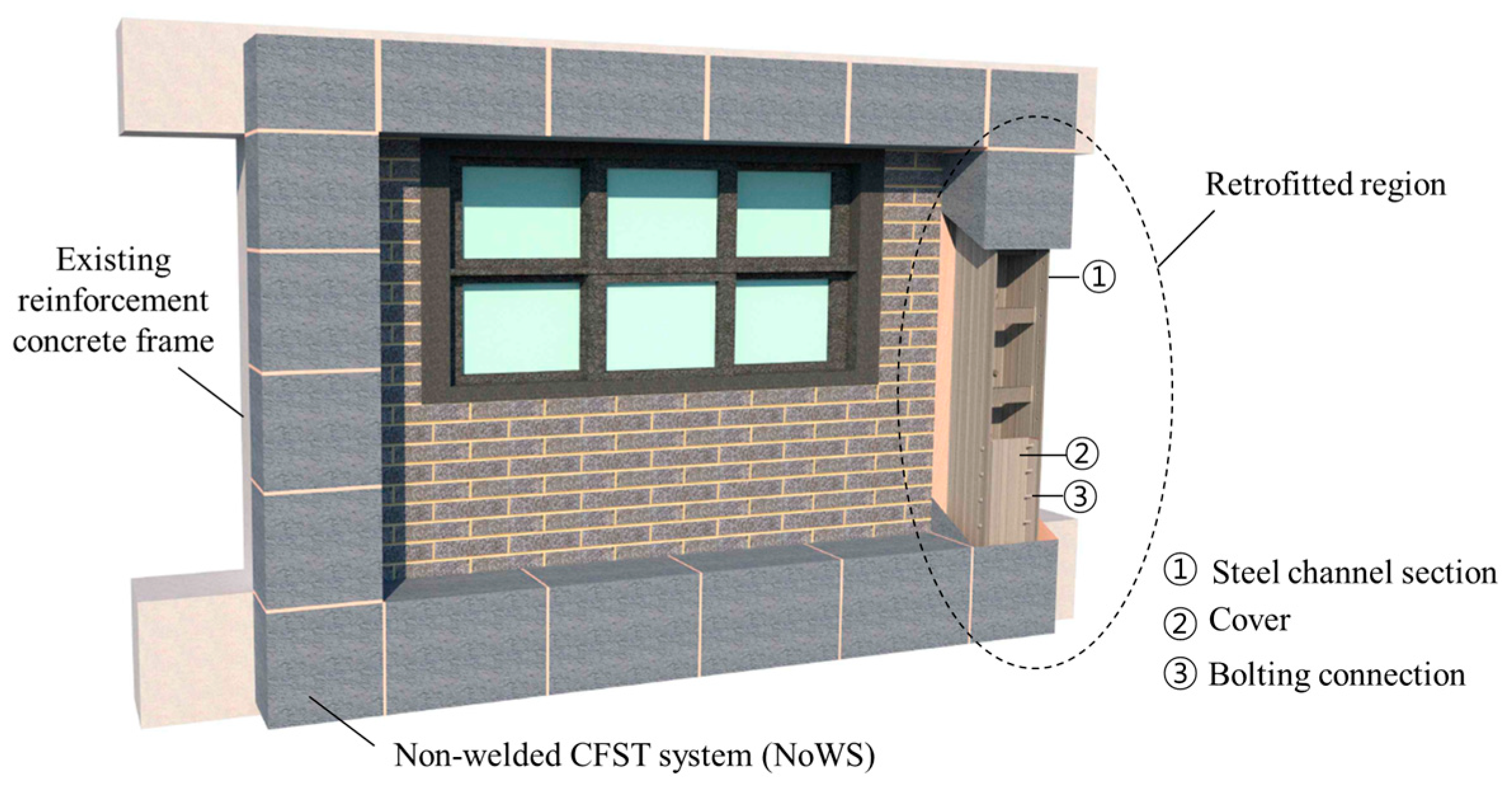
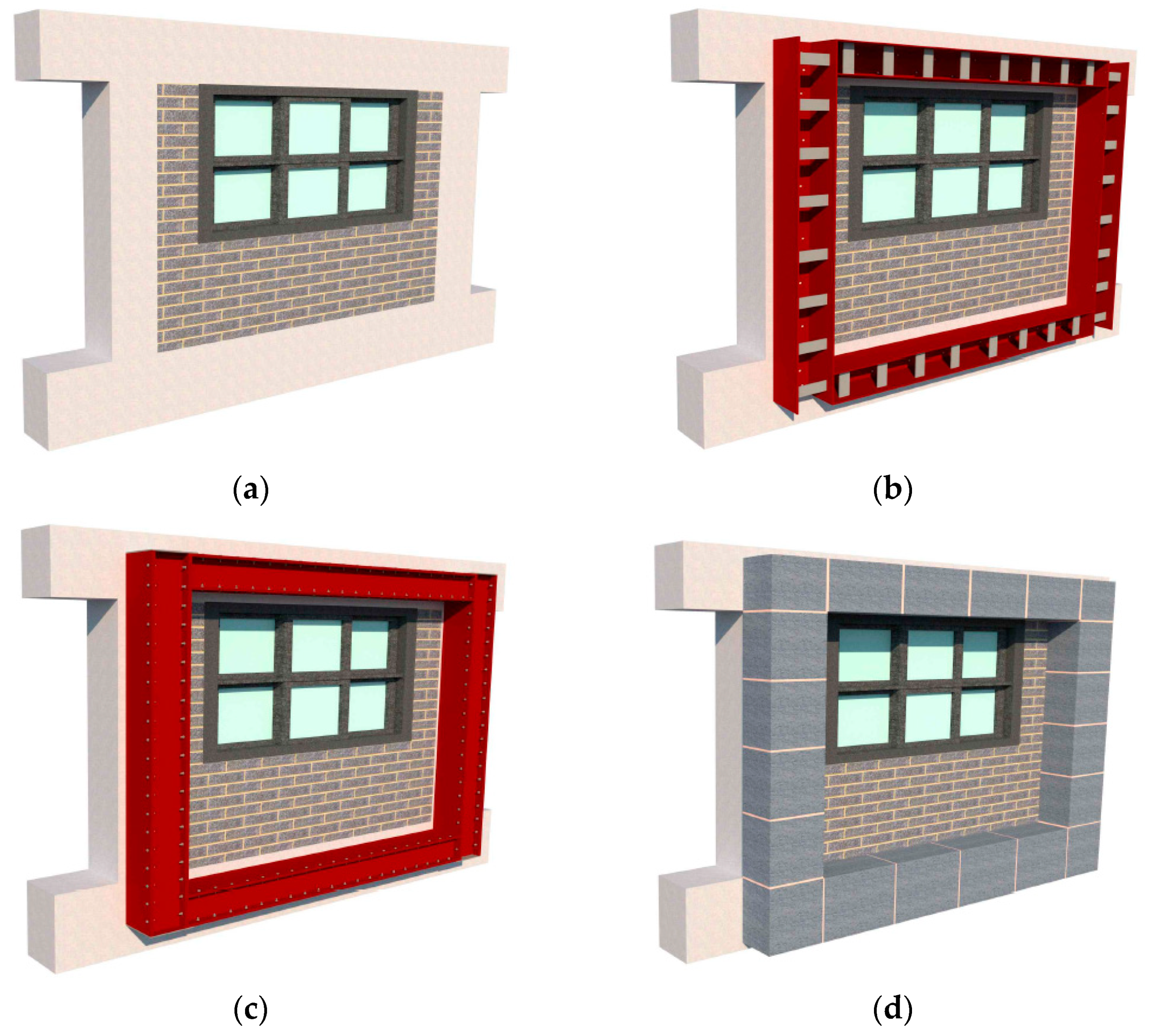
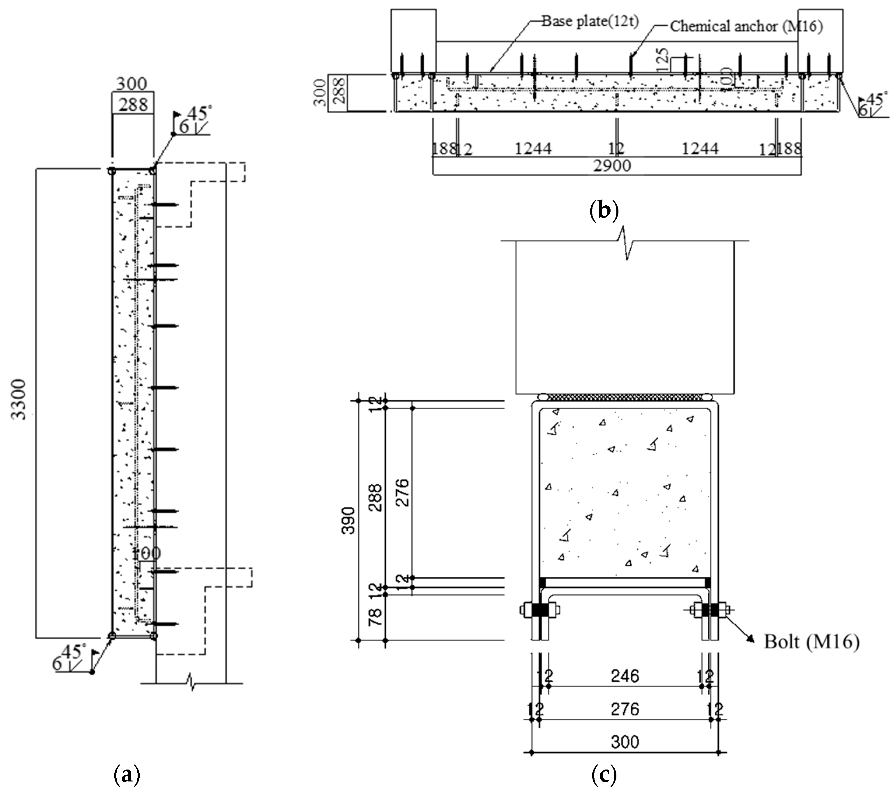
2. Description of the Non-Welded CFST
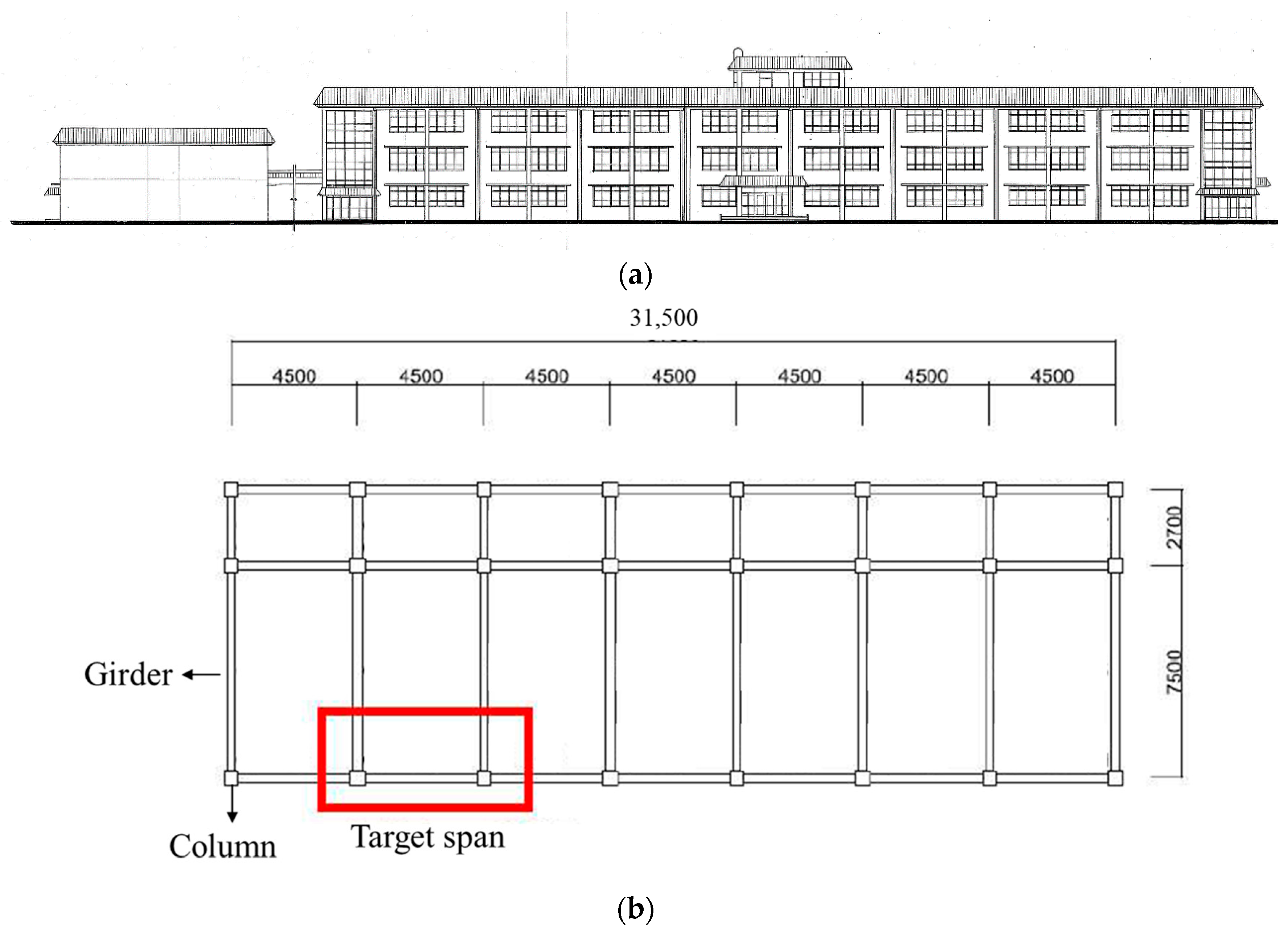
3. Experimental Program
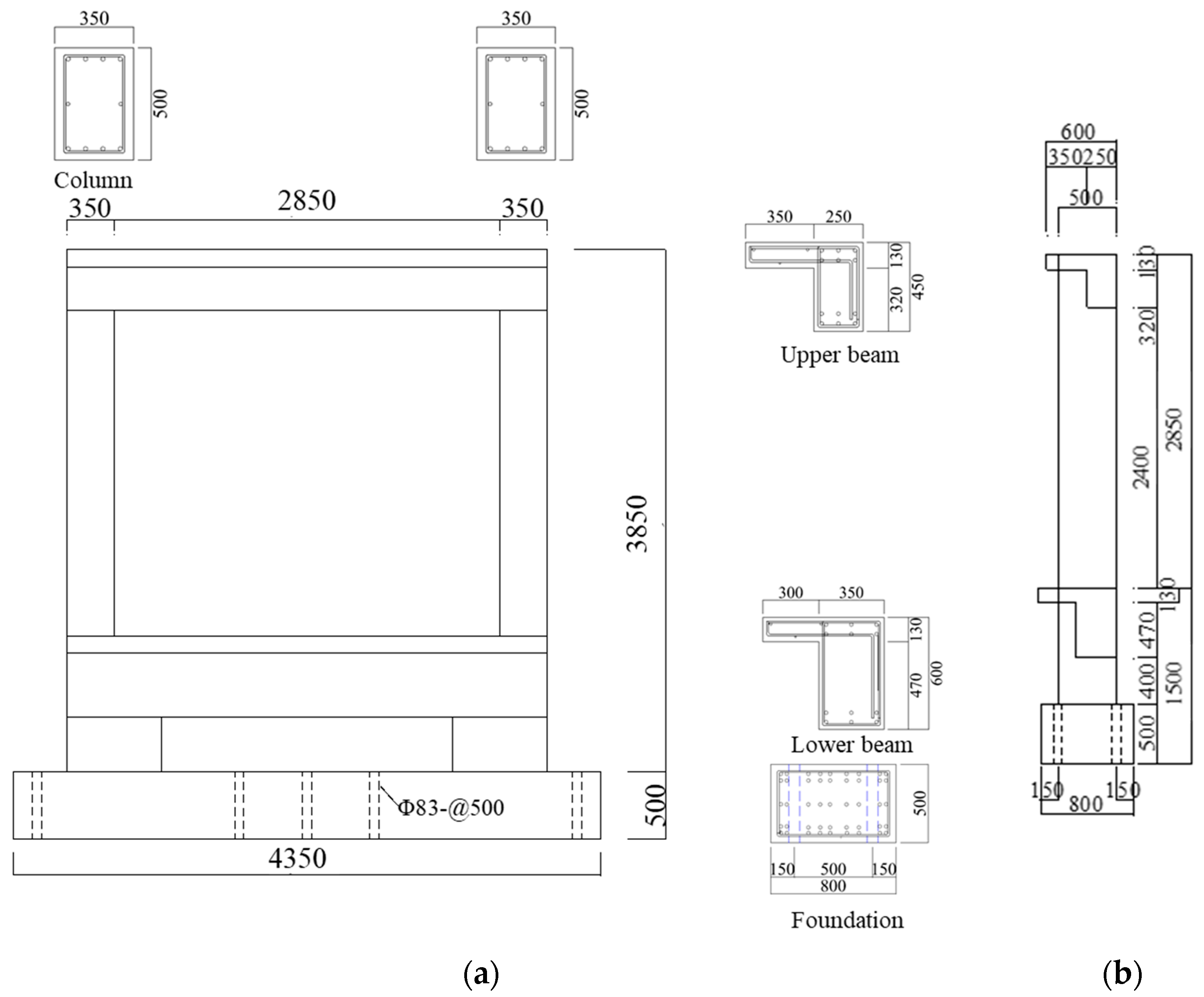
3.1. Specimen Descriptions
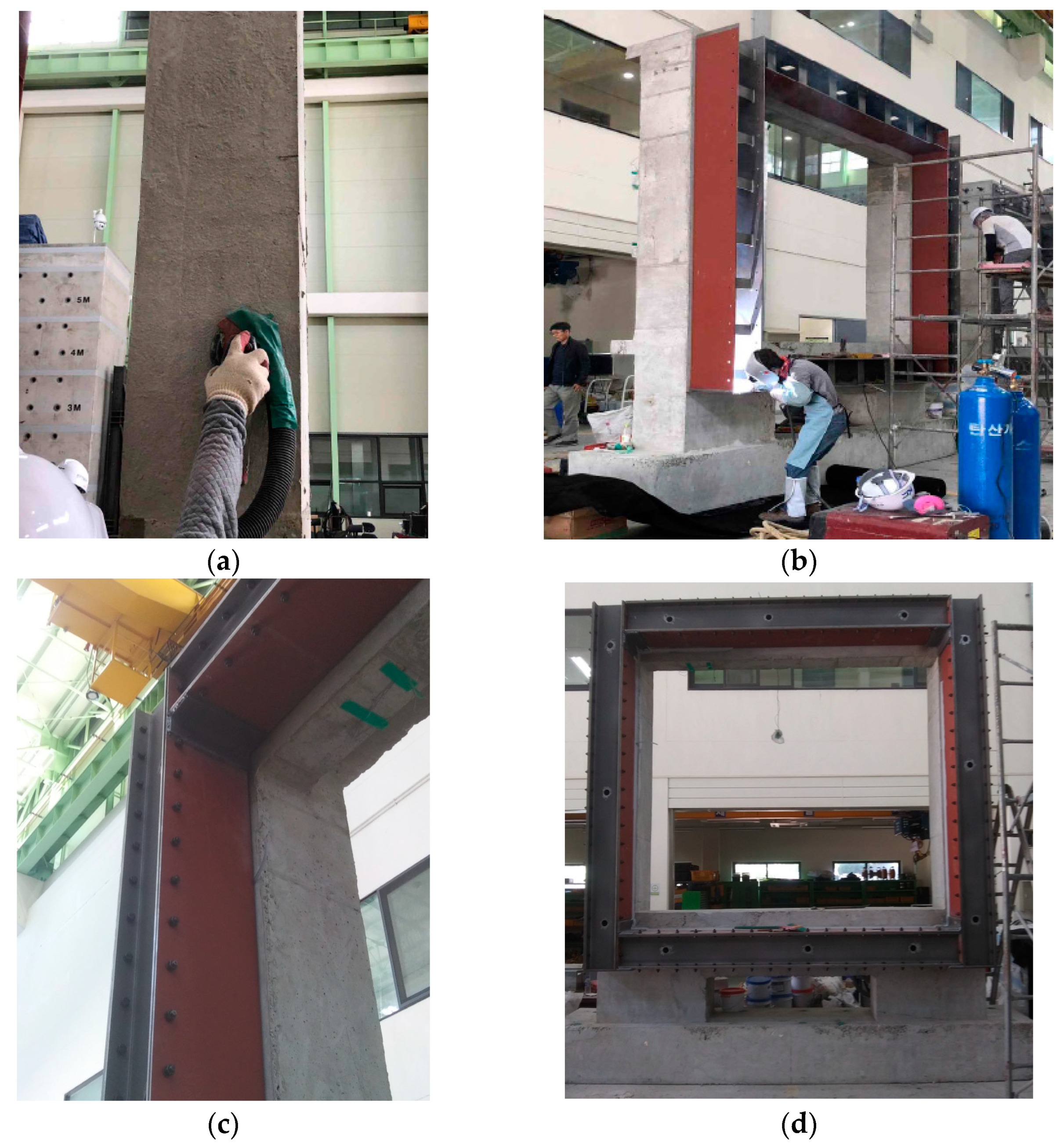
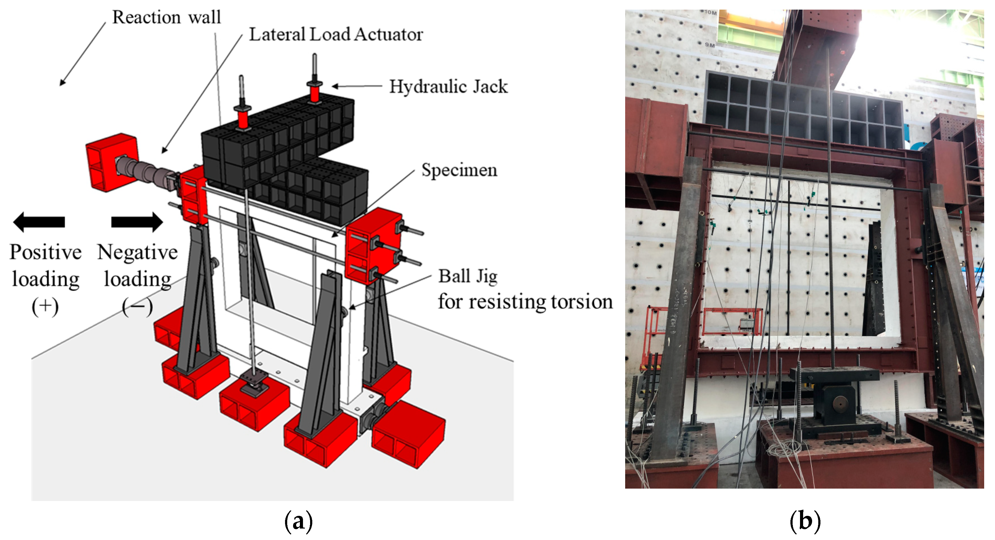
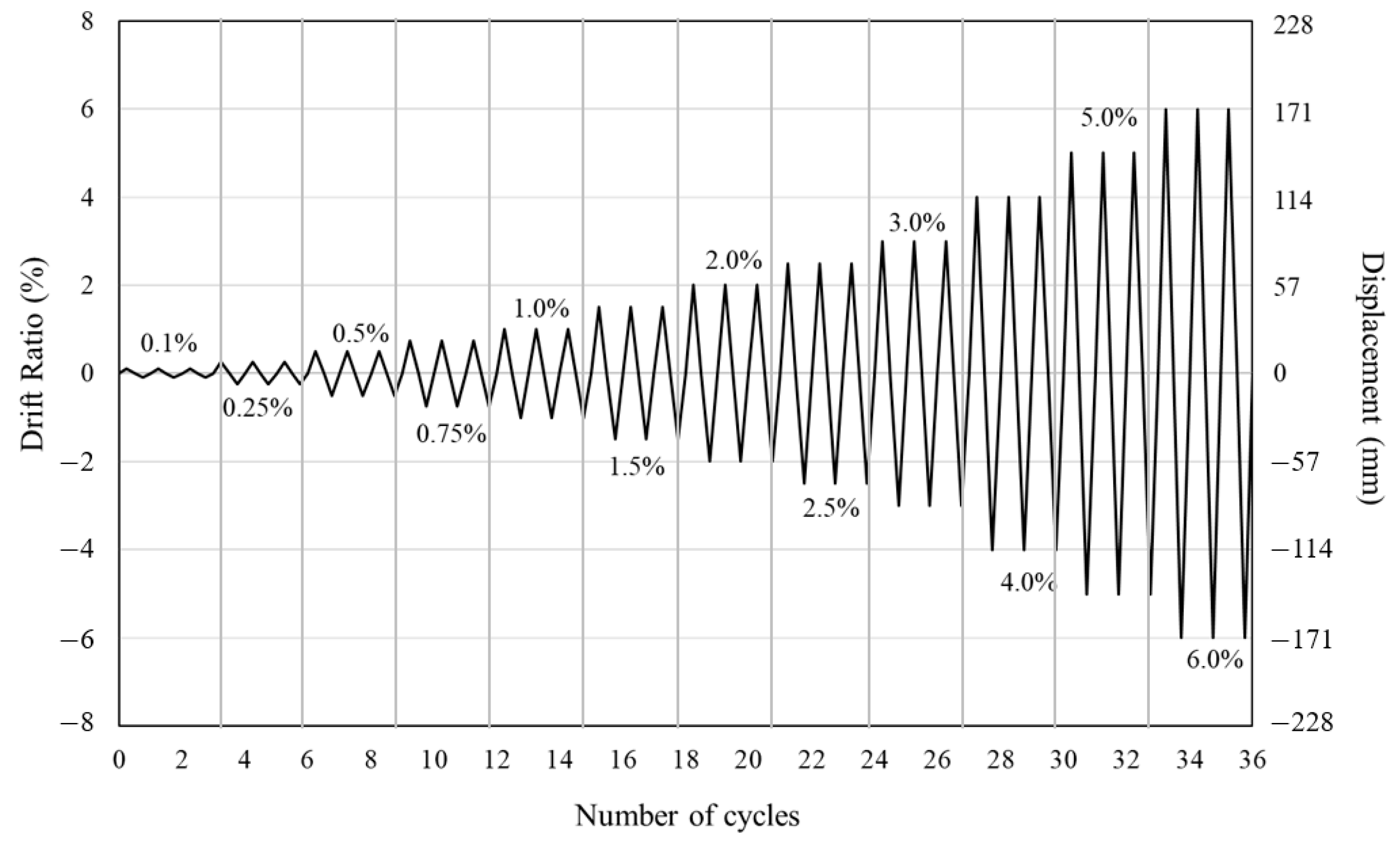
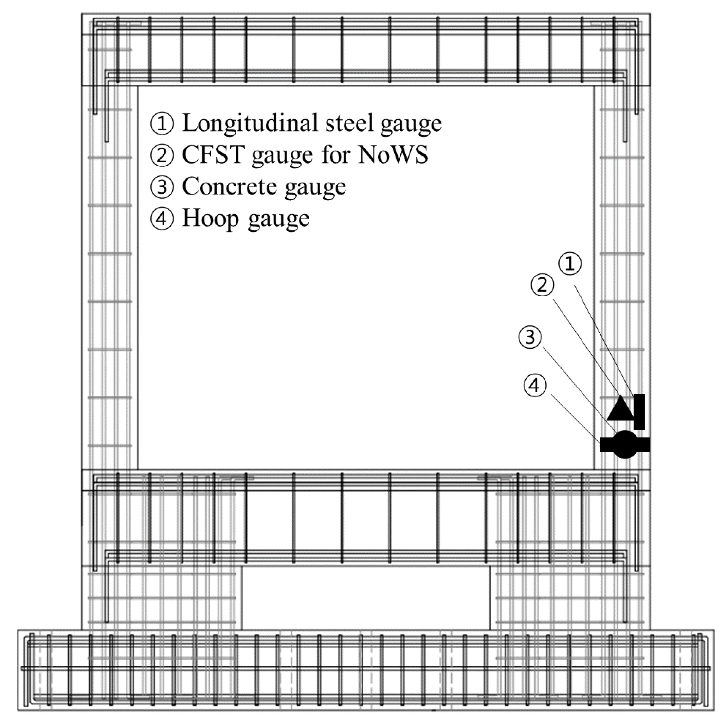
3.2. Experimental Setup and Loading Procedure
4. Results of Cyclic Loading Test and Discussions
4.1. Propagation of Cracks
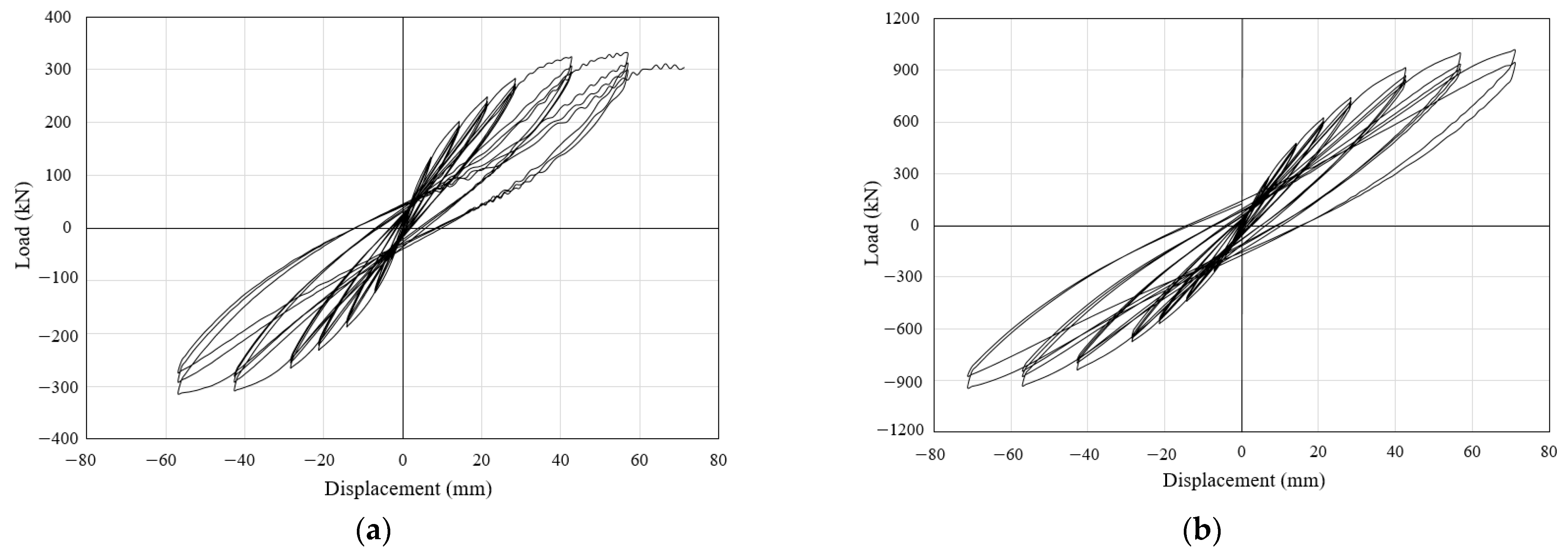
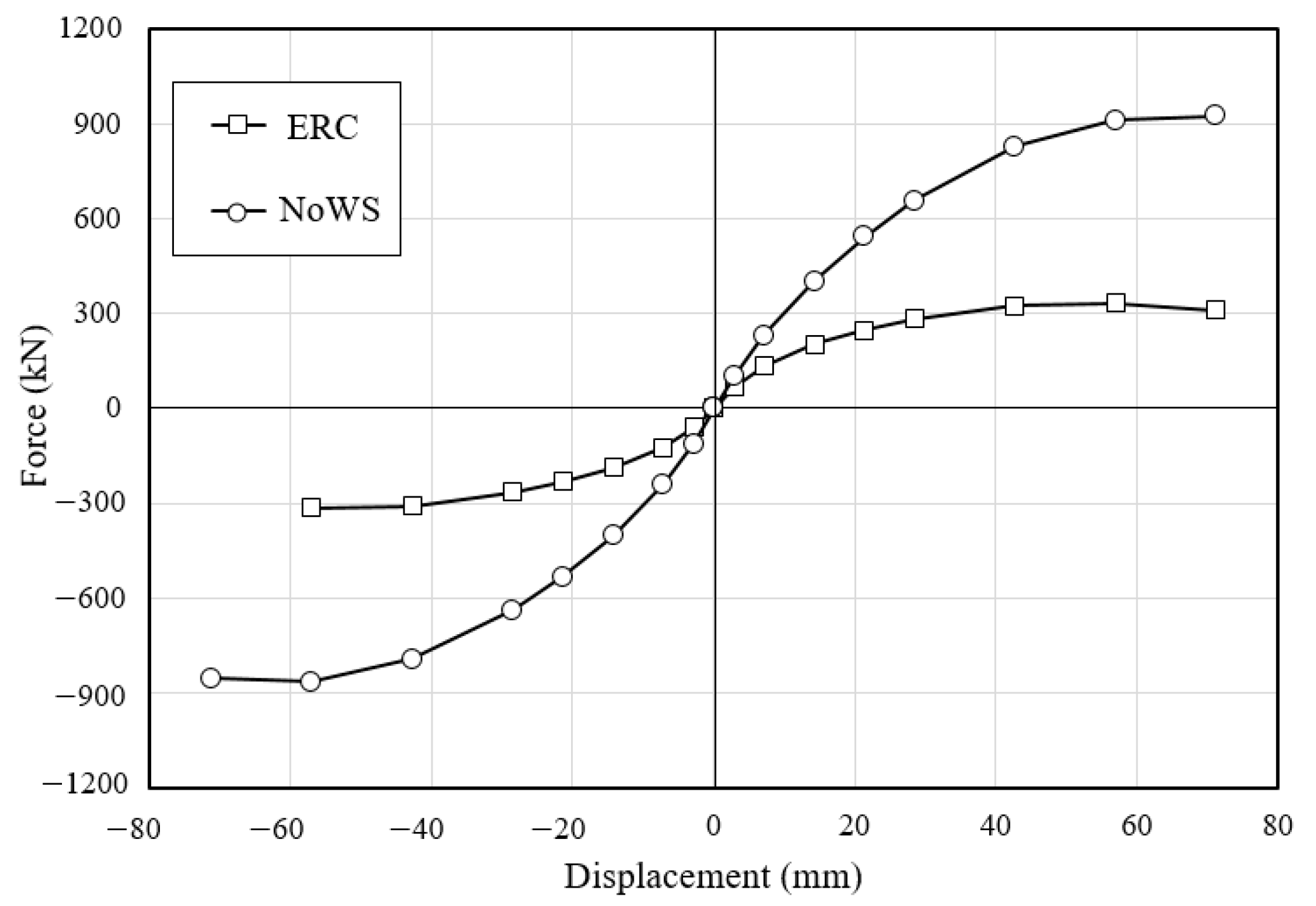
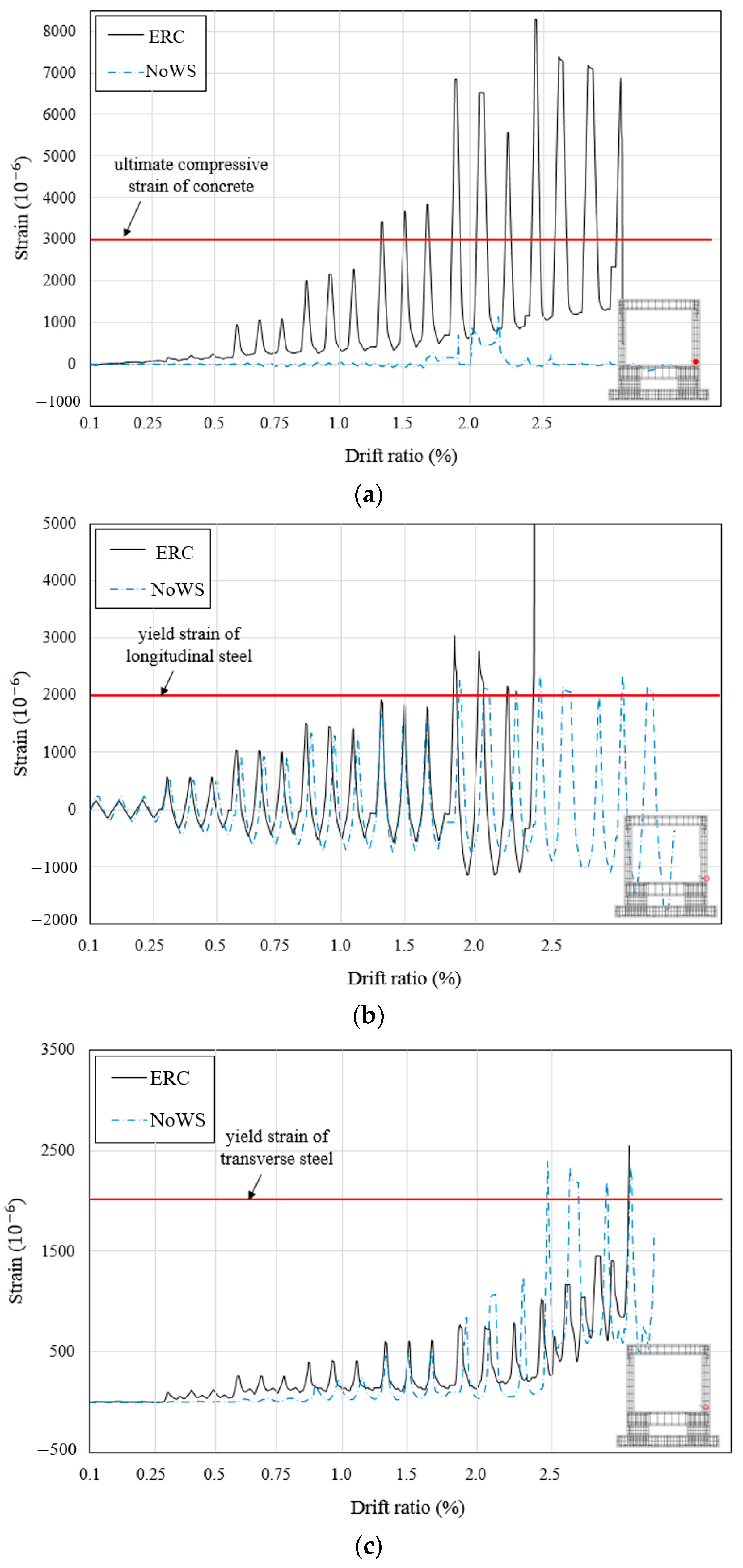
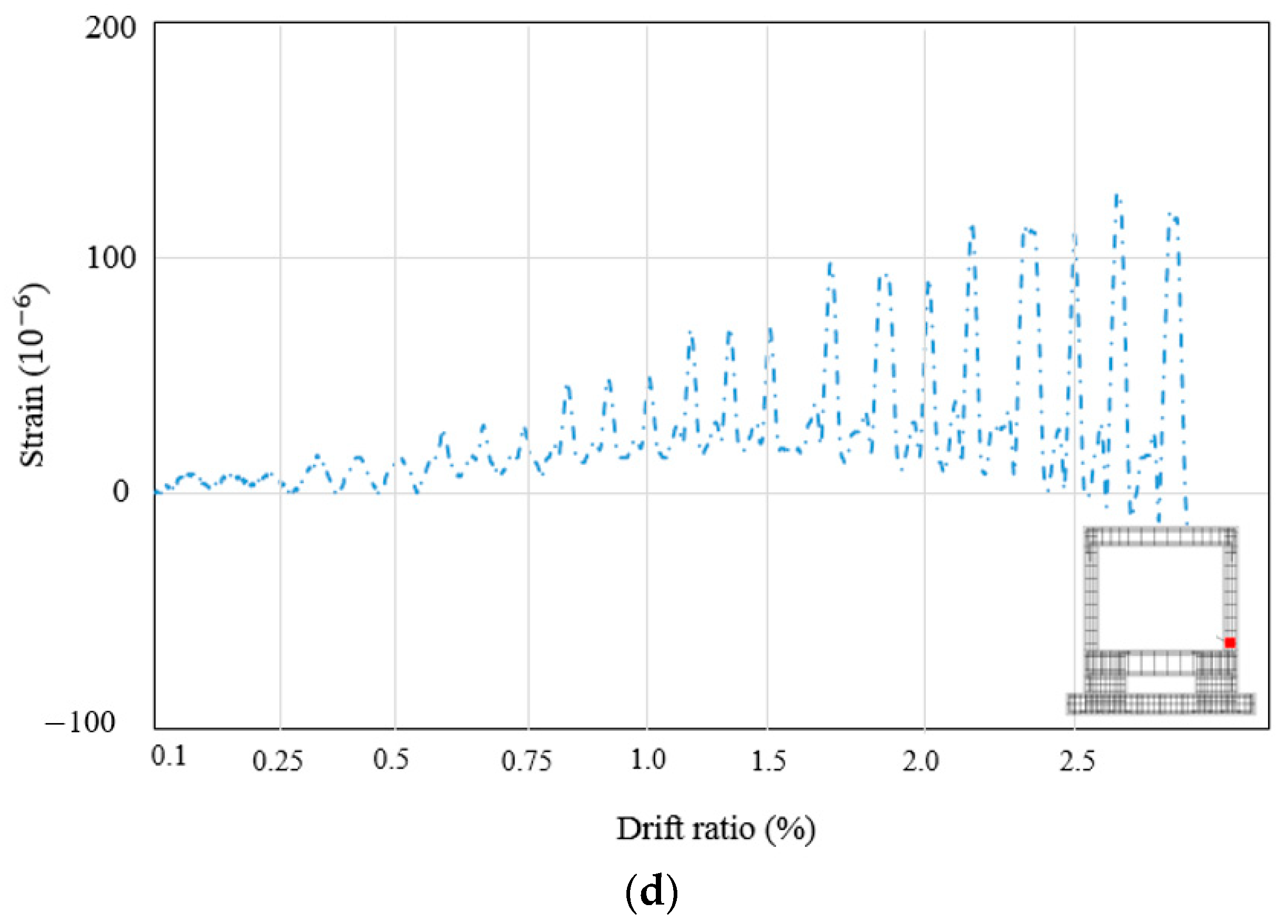
4.2. Load–Displacement Curve and Strain Behavior
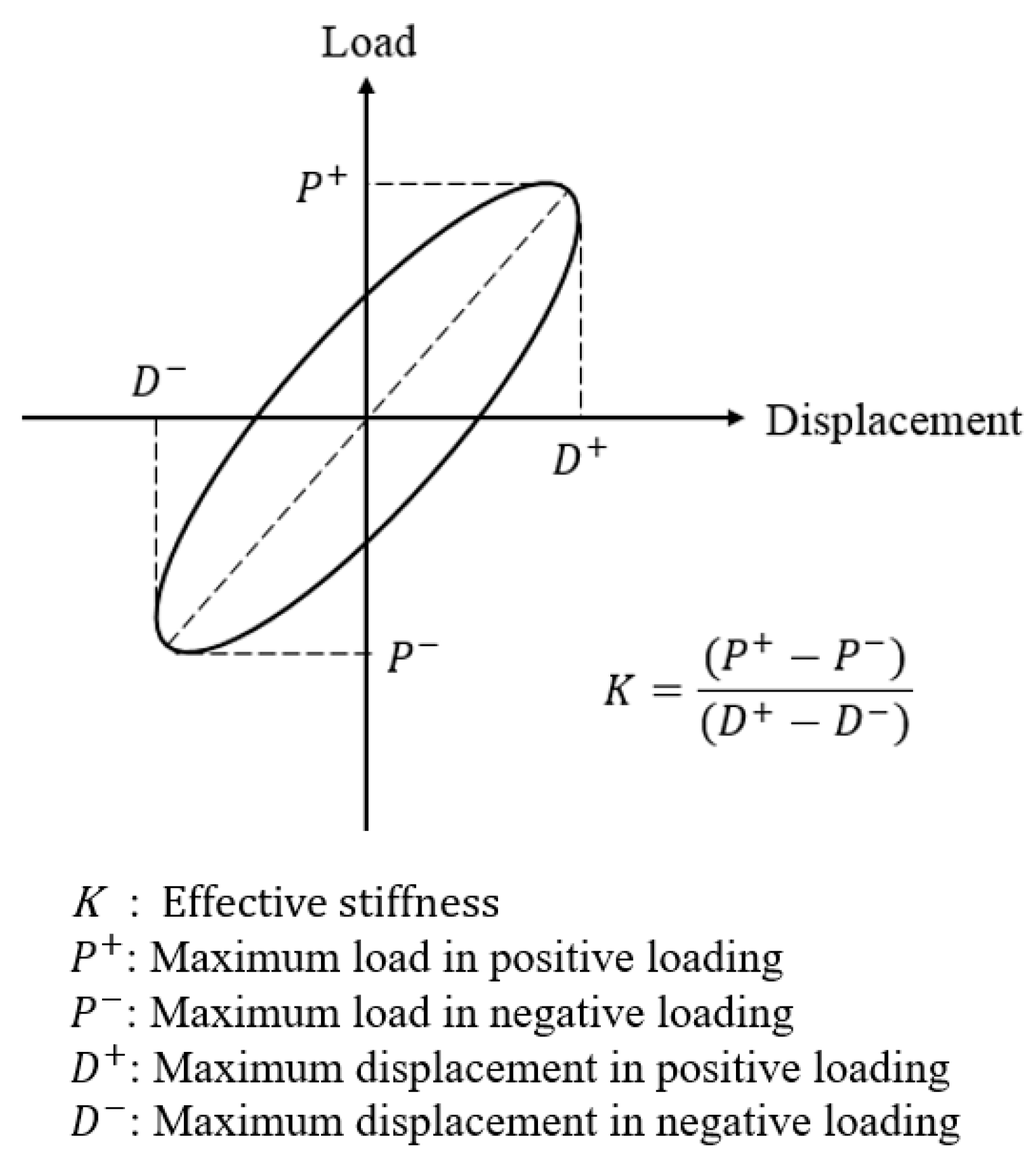
4.3. Comparison of Effective Stiffness
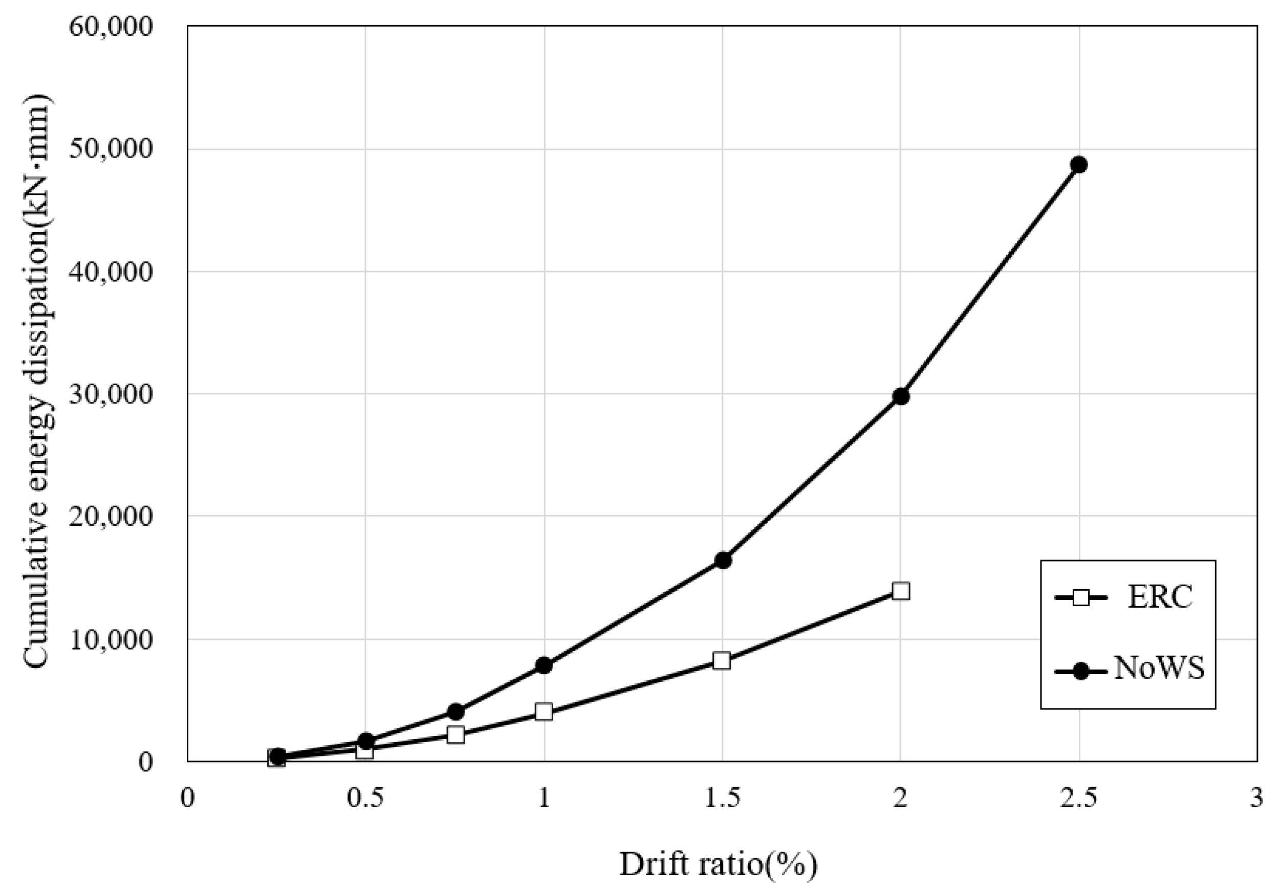
4.4. Energy Dissipation
5. Conclusions
Author Contributions
Funding
Institutional Review Board Statement
Informed Consent Statement
Data Availability Statement
Conflicts of Interest
References
- Julio, E.S.; Branco, F.; Silva, V.D. Structural rehabilitation of columns with reinforced concrete jacketing. Prog. Struct. Eng. Mater. 2003, 5, 29–37. [Google Scholar] [CrossRef] [Green Version]
- Julio, E.N.B.S.; Branco, F.A. Reinforced concrete jacketing-interface influence on cyclic loading response. ACI Struct. J. 2008, 105, 471. [Google Scholar]
- Tayeh, B.A.; Naja, M.A.; Shihada, S.; Arafa, M. Repairing and strengthening of damaged RC columns using thin concrete jacketing. Adv. Civ. Eng. 2019, 2019, 1–16. [Google Scholar] [CrossRef]
- Xue, J.; Lavorato, D.; Bergami, A.V.; Nuti, C.; Briseghella, B.; Marano, G.C.; Santini, S. Severely damaged reinforced concrete circular columns repaired by turned steel rebar and high-performance concrete jacketing with steel or polymer fibers. Appl. Sci. 2018, 8, 1671. [Google Scholar] [CrossRef] [Green Version]
- Faleschini, F.; Zanini, M.A.; Hofer, L.; Toska, K.; De Domenico, D.; Pellegrino, C. Confinement of reinforced concrete columns with glass fiber reinforced cementitious matrix jackets. Eng. Struct. 2020, 218, 110847. [Google Scholar] [CrossRef]
- Belal, M.F.; Mohamed, H.M.; Morad, S.A. Behavior of reinforced concrete columns strengthened by steel jacket. HBRC J. 2015, 11, 201–212. [Google Scholar] [CrossRef] [Green Version]
- Choi, E.; Chung, Y.S.; Park, C.; Kim, D.J. Seismic performance of circular RC columns retrofitted with prefabricated steel wrapping jackets. Mag. Concr. Res. 2013, 65, 1429–1440. [Google Scholar] [CrossRef]
- Fakharifar, M.; Chen, G.; Wu, C.; Shamsabadi, A.; ElGawady, M.A.; Dalvand, A. Rapid repair of earthquake-damaged RC columns with prestressed steel jackets. J. Bridge Eng. 2016, 21, 04015075. [Google Scholar] [CrossRef]
- Wang, L.; Su, R.K.L.; Cheng, B.; Li, L.Z.; Wan, L.; Shan, Z.W. Seismic behavior of preloaded rectangular RC columns strengthened with precambered steel plates under high axial load ratios. Eng. Struct. 2017, 152, 683–697. [Google Scholar] [CrossRef]
- Raza, S.; Khan, M.K.; Menegon, S.J.; Tsang, H.H.; Wilson, J.L. Strengthening and repair of reinforced concrete columns by jacketing: State-of-the-art review. Sustainability 2019, 11, 3208. [Google Scholar] [CrossRef] [Green Version]
- Triantafyllou, G.G.; Rousakis, T.C.; Karabinis, A.I. Axially loaded reinforced concrete columns with a square section partially confined by light GFRP straps. J. Compos. Constr. 2015, 19, 04014035. [Google Scholar] [CrossRef]
- Saljoughian, A.; Mostofinejad, D. Corner strip-batten technique for FRP-confinement of square RC columns under eccentric loading. J. Compos. Constr. 2016, 20, 04015077. [Google Scholar] [CrossRef]
- Mai, A.D.; Sheikh, M.N.; Hadi, M.N. Investigation on the behaviour of partial wrapping in comparison with full wrapping of square RC columns under different loading conditions. Constr. Build. Mater. 2018, 168, 153–168. [Google Scholar] [CrossRef] [Green Version]
- Wang, W.; Sheikh, M.N.; Al-Baali, A.Q.; Hadi, M.N. Compressive behaviour of partially FRP confined concrete: Experimental observations and assessment of the stress-strain models. Constr. Build. Mater. 2018, 192, 785–797. [Google Scholar] [CrossRef] [Green Version]
- Mao, X.Y.; Xiao, Y. Seismic behavior of confined square CFT columns. Eng. Struct. 2006, 28, 1378–1386. [Google Scholar] [CrossRef]
- Xiao, Y.; Zhang, Z.; Hu, J.; Kunnath, S.K.; Guo, P. Seismic behavior of CFT column and steel pile footings. J. Bridge Eng. 2011, 16, 575–586. [Google Scholar] [CrossRef]
- Li, B.; Wang, J.; Baniotopoulos, C.C.; Yang, J.; Hu, Y. Seismic design and pseudo-dynamic tests of blind-bolted CFT frames with buckling-restrained braces. J. Constr. Steel Res. 2020, 167, 105857. [Google Scholar] [CrossRef]
- Tao, Z.; Han, L.H.; Zhuang, J.P. Axial loading behavior of CFRP strengthened concrete-filled steel tubular stub columns. Adv. Struct. Eng. 2007, 10, 37–46. [Google Scholar] [CrossRef]
- Kawabata, Y.; Ohya, Y.; Kato, E.; Iwanami, M. Experimental study on effectiveness of retrofitting via normal strength concrete filling on damaged circular steel tubes subjected to axial and horizontal loads. Constr. Build. Mater. 2017, 154, 1–9. [Google Scholar] [CrossRef]
- Dai, Z.; Dai Pang, S.; Liew, J.R. Axial load resistance of grouted sleeve connection for modular construction. Thin Walled Struct. 2020, 154, 106883. [Google Scholar] [CrossRef]
- Popov, E.P.; Takhirov, S.M. Bolted large seismic steel beam-to-column connections Part 1: Experimental study. Eng. Struct. 2002, 24, 1523–1534. [Google Scholar] [CrossRef]
- Inoue, K.; Suita, K.; Takeuchi, I.; Chusilp, P.; Nakashima, M.; Zhou, F. Seismic-resistant weld-free steel frame buildings with mechanical joints and hysteretic dampers. J. Struct. Eng. 2006, 132, 864–872. [Google Scholar] [CrossRef]
- Kim, D.K.; Lee, C.H. Experimental and analytical study of combined bolted-welded lap joints including high-strength steel. J. Constr. Steel Res. 2020, 168, 105995. [Google Scholar] [CrossRef]
- Ro, K.M.; Kim, M.S.; Lee, Y.H. Experimental Study on Seismic Retrofitting of Reinforced Concrete Frames Using Welded Concrete-Filled Steel Tubes. Appl. Sci. 2020, 10, 7061. [Google Scholar] [CrossRef]
- ACI Committee 374. Acceptance Criteria for Moment Frames Based on Structural Testing and Commentary (ACI 374.1R-05); American Concrete Institute (ACI): Farmington Hills, MI, USA, 2005. [Google Scholar]
- Korea Construction Standard Center. Korean Design Standard (KDS 41 10 15); Ministry of Land, Infrastructure and Transport: Sejong, Korea, 2019.
- Tsonos, A.G. Lateral load response of strengthened reinforced concrete beam-to-column joints. ACI Struct. J. 1999, 96, 46–56. [Google Scholar]

| Members | Dimension (mm) | Reinforcement | Section (mm) | |
|---|---|---|---|---|
| Longitudinal | Transverse | |||
| Column | 350 × 500 × 2850 | 8-D19, 2-D16 | D10@300 mm |  |
| Upper beam | 250 × 450 × 3200 | 6-D22 | Mid: D10@300 mm End: D10@200 mm |  |
| Lower beam | 350 × 600 × 3200 | 6-D22 | Mid: D10@300 mm End: D10@200 mm | 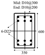 |
| Foundation | 800 × 500 × 4350 | 45-D22 | D16@130 mm | 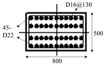 |
| CFST | 300 × 300 × 12 | - | - | 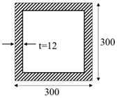 |
| Drift Ratio (%) | Specimens | |
|---|---|---|
| ERC | NoWS | |
| 1.5 |  | 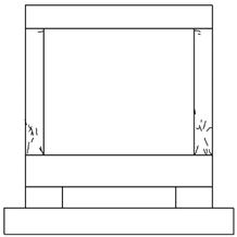 |
| 2.0 |  | 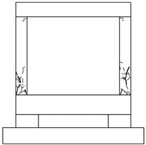 |
| 2.5 | 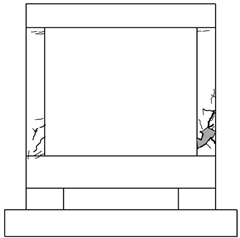 | 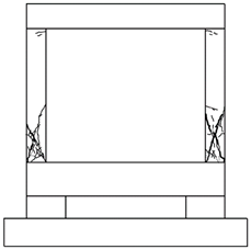 |
| Location | Crack Propagation | Observed Damage | |
|---|---|---|---|
| ERC | NoWS | ||
| Lower beam–column joint | 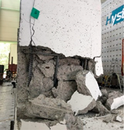 | 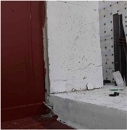 | -Severe spalling of the concrete and bending of the lateral reinforcement in the ERC; -No buckling deformation or separation of the CFST frames occurred, and no bolt loosening in the NoWS. |
| Left column | 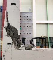 |  | -Severe concrete spalling occurred at the end of the column. |
| Drift Ratio (%) | Load According to Direction (kN) | Load Ratio of NoWS to the ERC | ||||
|---|---|---|---|---|---|---|
| ERC | NoWS | |||||
| Positive | Negative | Positive | Negative | Positive | Negative | |
| 0.1 | 67.70 | −59.47 | 99.88 | −110.75 | 1.48 | 1.86 |
| 0.25 | 134.25 | −123.20 | 229.64 | −238.9 | 1.71 | 1.94 |
| 0.5 | 201.80 | −187.75 | 402.39 | −402.34 | 1.99 | 2.14 |
| 0.75 | 248.33 | −231.71 | 543.69 | −533.64 | 2.19 | 2.30 |
| 1.0 | 283.10 | −265.51 | 656.53 | −637.56 | 2.32 | 2.40 |
| 1.5 | 323.96 | −308.32 | 826.84 | −790.96 | 2.55 | 2.57 |
| 2.0 | 332.00 | −314.21 | 911.77 | −863.17 | 2.75 | 2.75 |
| 2.5 | 311.39 | - | 924.32 | −853.61 | 2.97 | - |
| Drift Ratio (%) | Values of Effective Stiffness (kN/mm) | Effective Stiffness Ratio of ERC to the NoWS | |
|---|---|---|---|
| ERC | NoWS | ||
| 0.1 | 22.31 | 36.95 | 1.66 |
| 0.25 | 18.07 | 32.88 | 1.82 |
| 0.5 | 13.67 | 28.24 | 2.07 |
| 0.75 | 11.23 | 25.20 | 2.24 |
| 1.0 | 9.62 | 22.70 | 2.36 |
| 1.5 | 7.40 | 18.92 | 2.56 |
| 2.0 | 5.67 | 15.57 | 2.75 |
| 2.5 | - | 12.48 | - |
| Drift Ratio (%) | Energy Dissipation (kN·mm) | Ratio of NoWS to the ERC | |
|---|---|---|---|
| ERC | NoWS | ||
| 0.1 | 190.49 | 324.47 | 1.70 |
| 0.25 | 436.75 | 729.5 | 1.67 |
| 0.5 | 1398.96 | 2386.22 | 1.71 |
| 0.75 | 3575.80 | 6423.29 | 1.80 |
| 1.0 | 7532.15 | 14,189.65 | 1.88 |
| 1.5 | 15,679.67 | 30,604.35 | 1.95 |
| 2.0 | 29,543.71 | 60,392.80 | 2.04 |
| 2.5 | - | 109,043.16 | - |
Publisher’s Note: MDPI stays neutral with regard to jurisdictional claims in published maps and institutional affiliations. |
© 2021 by the authors. Licensee MDPI, Basel, Switzerland. This article is an open access article distributed under the terms and conditions of the Creative Commons Attribution (CC BY) license (https://creativecommons.org/licenses/by/4.0/).
Share and Cite
Ro, K.M.; Kim, M.S.; Hwang, D.-S.; Lee, Y.H. Seismic Performance of Full-Scale Reinforced Concrete Frames Retrofitted with Bolted Concrete-Filled Steel Tubes. Appl. Sci. 2021, 11, 7382. https://doi.org/10.3390/app11167382
Ro KM, Kim MS, Hwang D-S, Lee YH. Seismic Performance of Full-Scale Reinforced Concrete Frames Retrofitted with Bolted Concrete-Filled Steel Tubes. Applied Sciences. 2021; 11(16):7382. https://doi.org/10.3390/app11167382
Chicago/Turabian StyleRo, Kyong Min, Min Sook Kim, Dae-Sung Hwang, and Young Hak Lee. 2021. "Seismic Performance of Full-Scale Reinforced Concrete Frames Retrofitted with Bolted Concrete-Filled Steel Tubes" Applied Sciences 11, no. 16: 7382. https://doi.org/10.3390/app11167382
APA StyleRo, K. M., Kim, M. S., Hwang, D.-S., & Lee, Y. H. (2021). Seismic Performance of Full-Scale Reinforced Concrete Frames Retrofitted with Bolted Concrete-Filled Steel Tubes. Applied Sciences, 11(16), 7382. https://doi.org/10.3390/app11167382