
Multilateration Approach for Wide Range Visible Light Indoor Positioning System Using Mobile CMOS Image Sensor


Abstract
:1. Introduction
- Practical System: Designed and implemented an efficient VLP system using existing LED light infrastructure. The LED drivers were modified slightly to transmit the location information to the image sensor.
- Test Area Accuracy: Implemented a multilateration positioning approach for this system, which utilized VLC and mobile CMOS image sensors for providing location-based service in a large indoor environment with many LEDs. The system ensures good accuracy and high precision within an area measuring 2.5 m × 4.5 m.
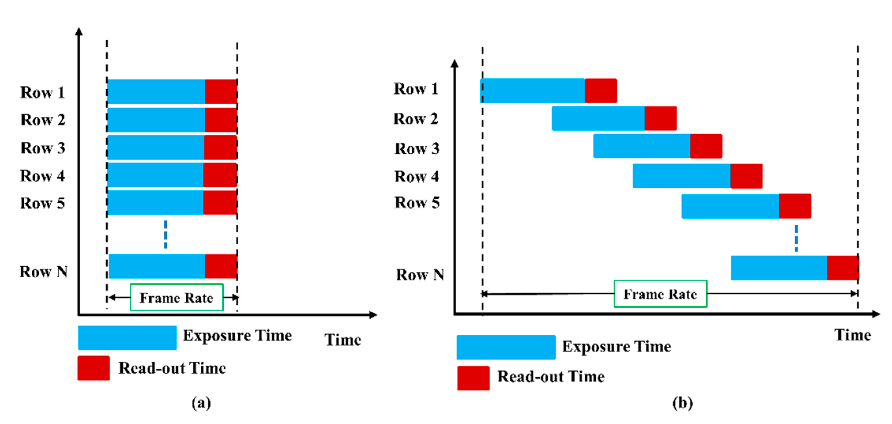
- Sensor: Smartphone-embedded low-cost CMOS image sensor with a rolling shutter mechanism was used to scan every image pixel for increasing the data rate. However, no additional device was required at the receiver, affording a simple system.
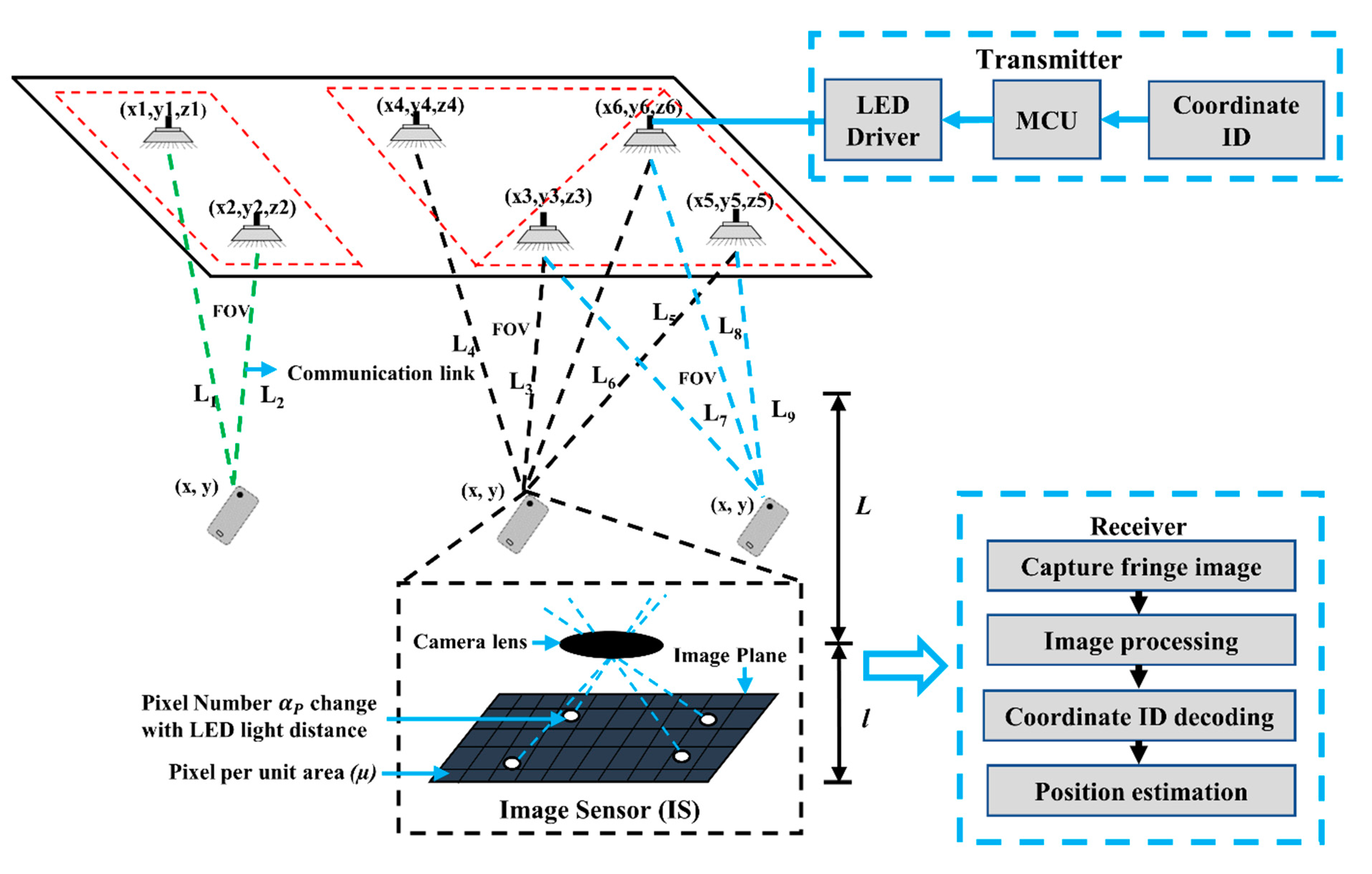
2. System Design
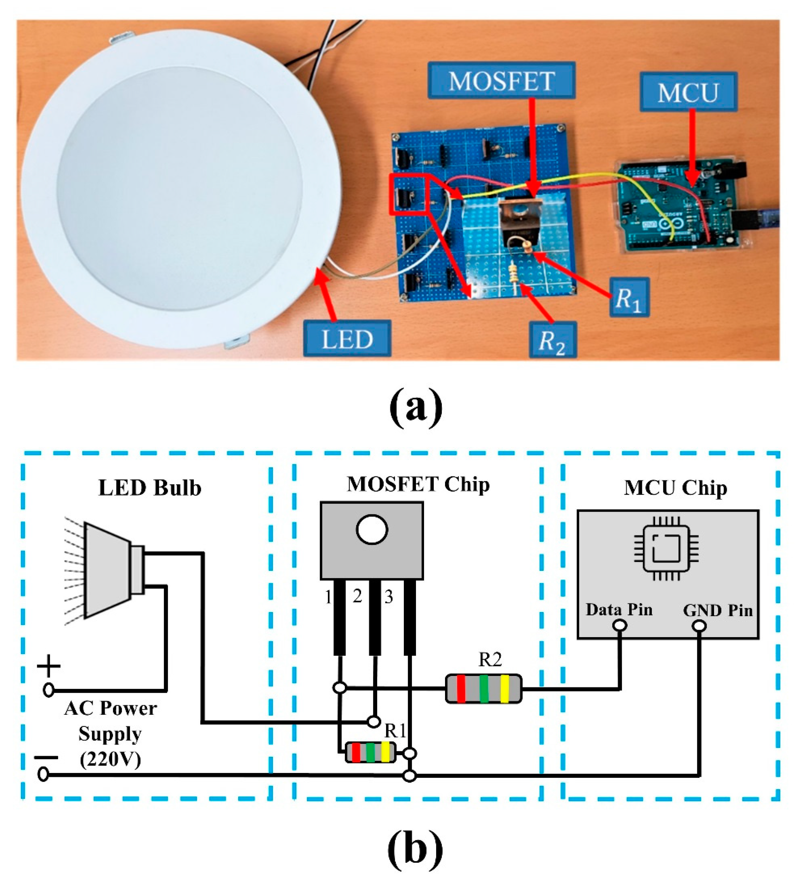
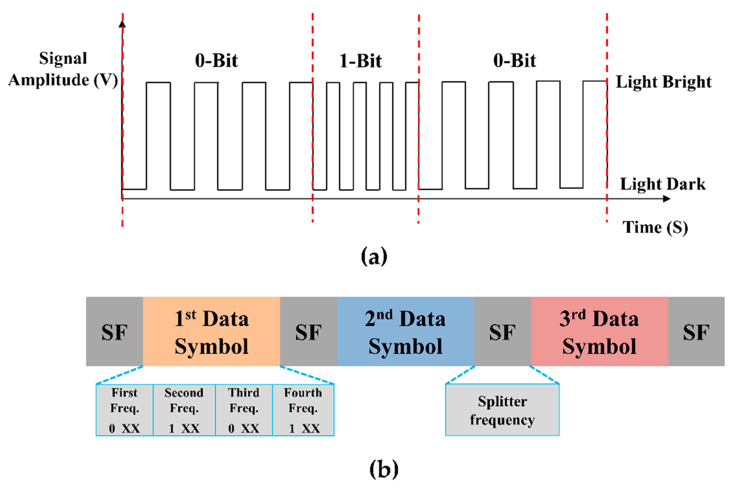
2.1. Transmitter
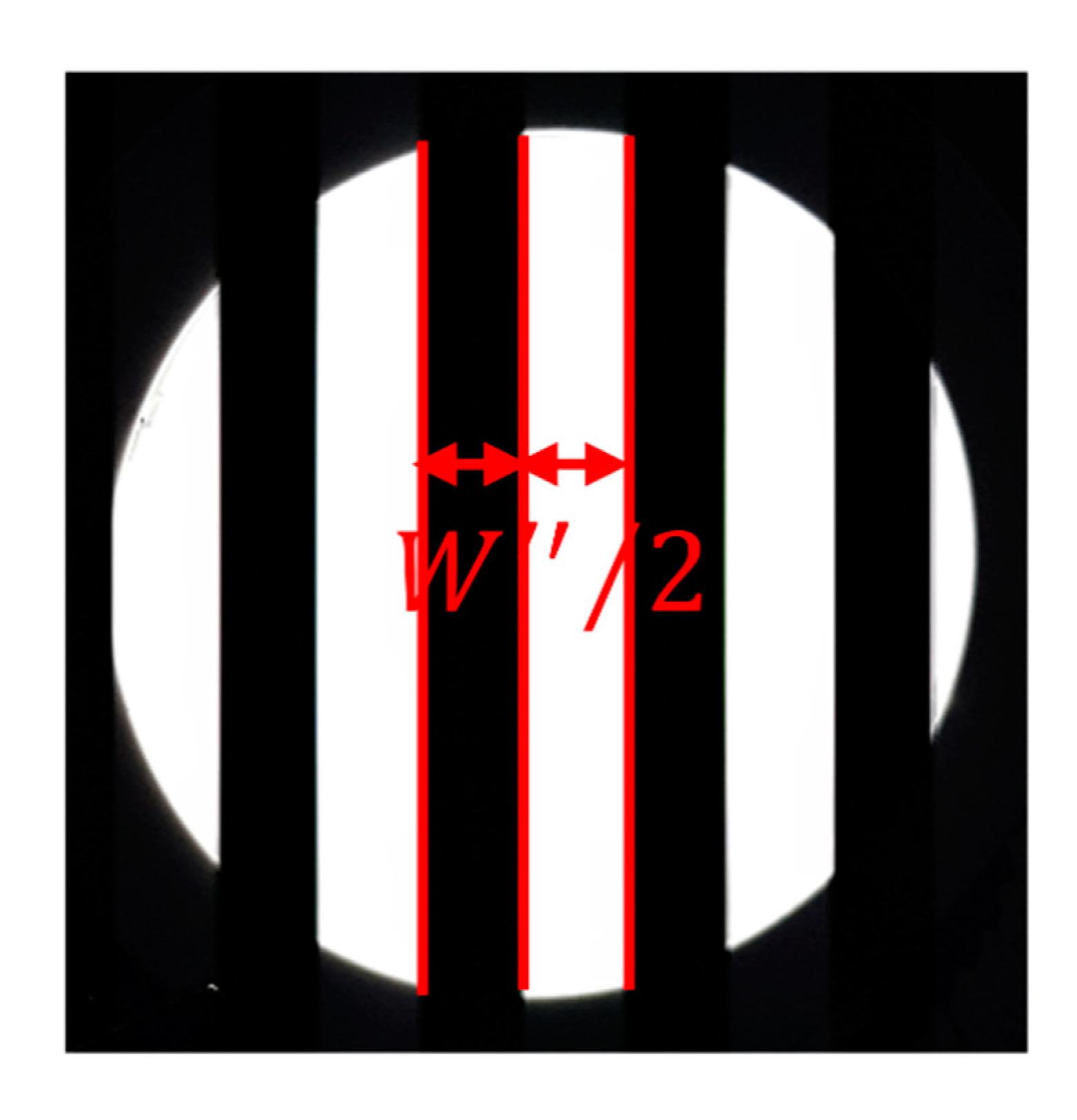
2.2. Receiver
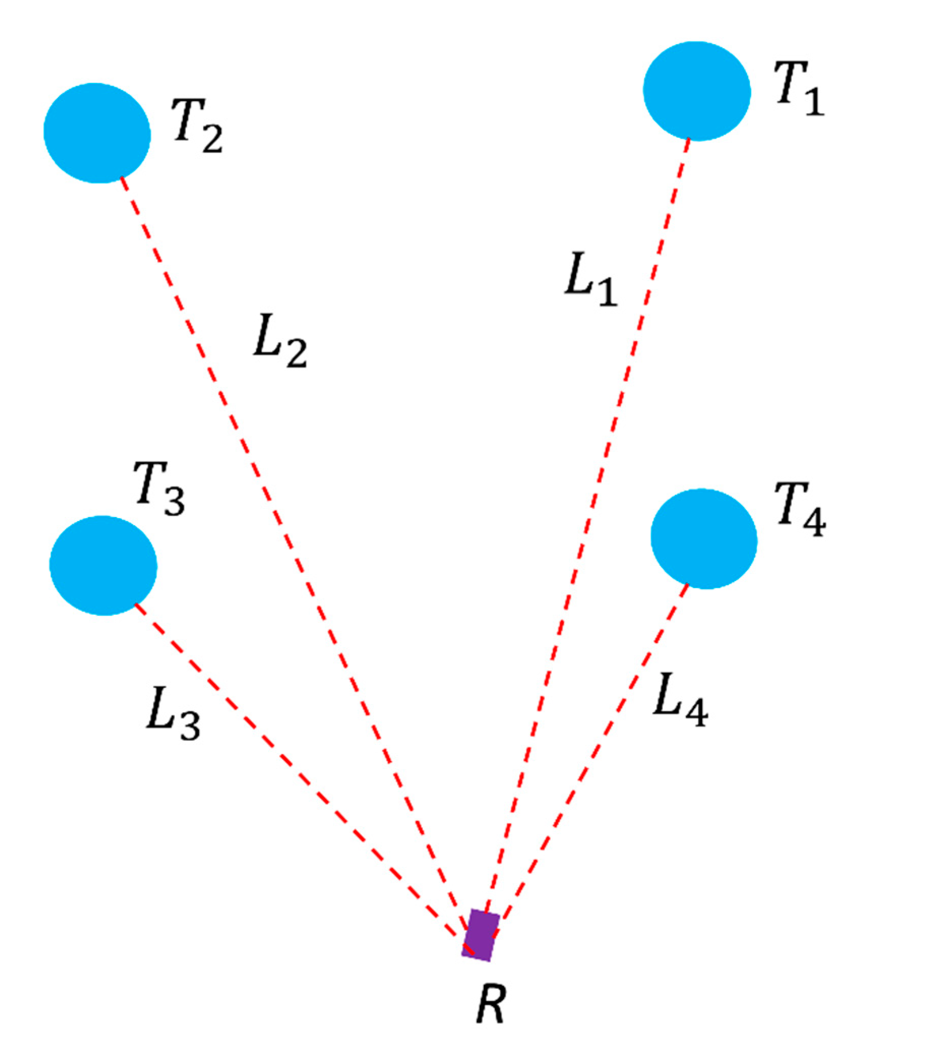
2.3. Multilateration Principle
3. Positioning Method
3.1. CMOS Image Sensor and LED Light Distance
3.2. Calculation of Image Area of Image Sensor and Location Change with Camera FOV
3.3. Coordinate Distance Estimation
4. Experimental Results
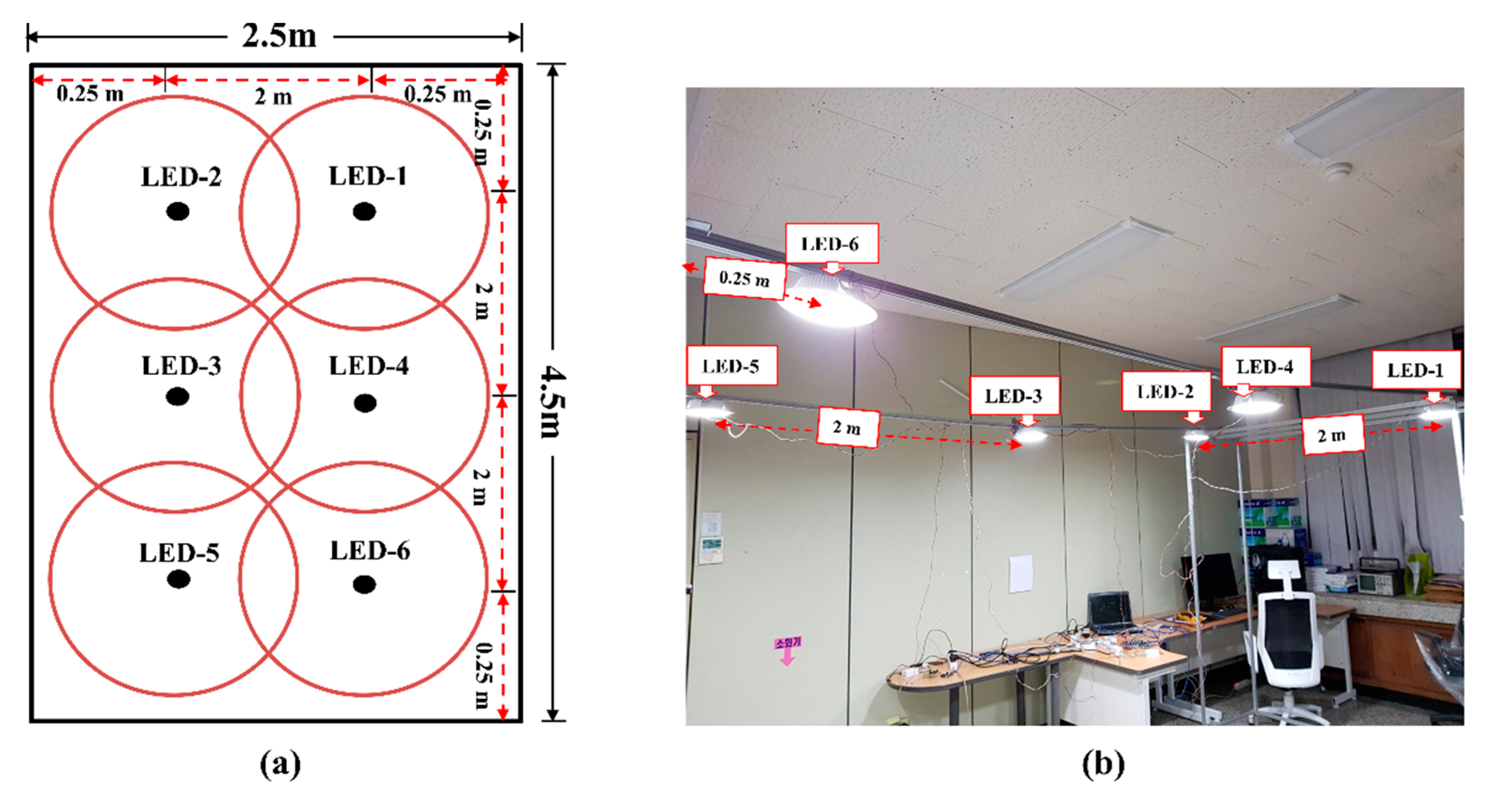
4.1. Experiment Setup
4.2. Experimental Result Evaluation
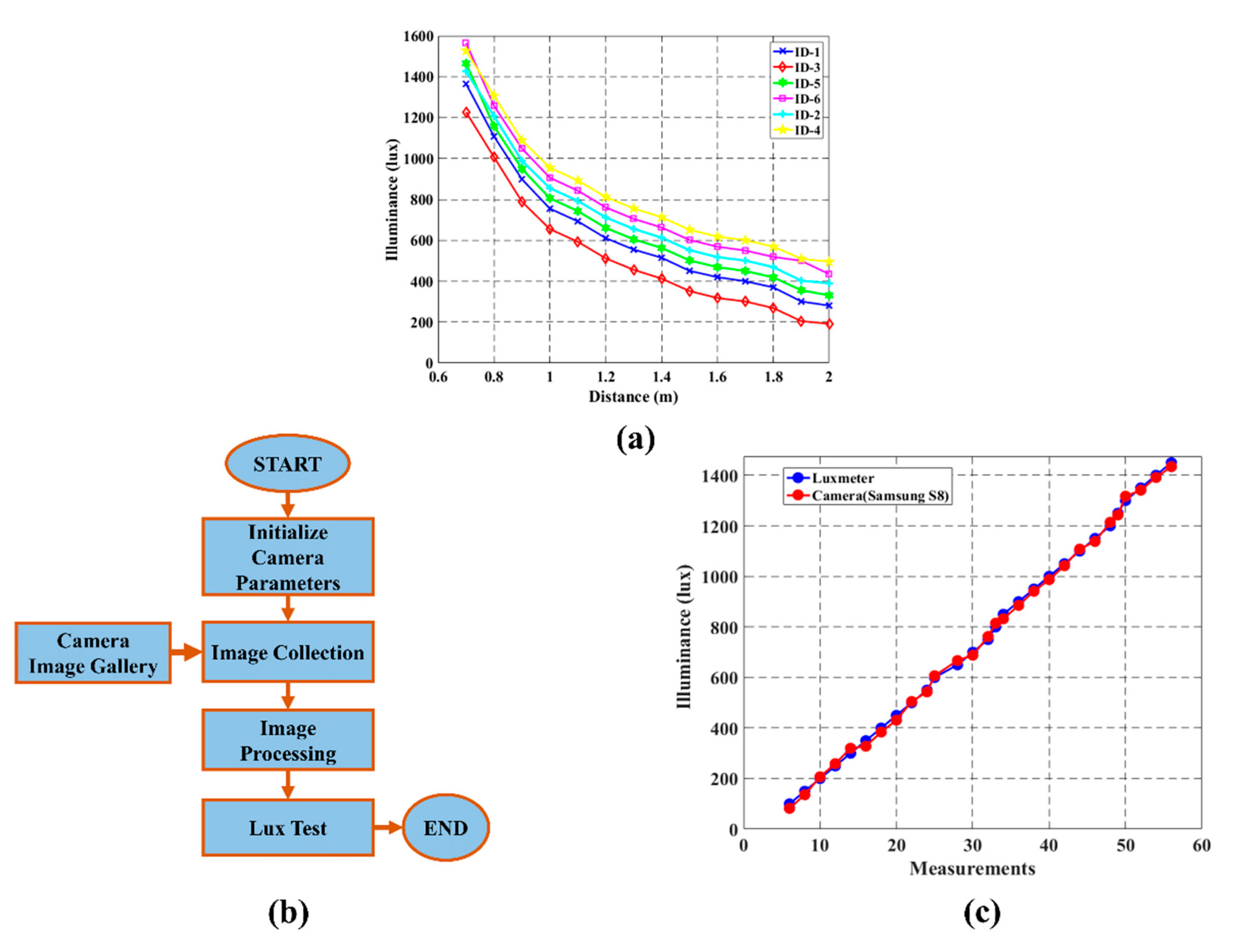
4.2.1. Light Intensity Measurement Performance
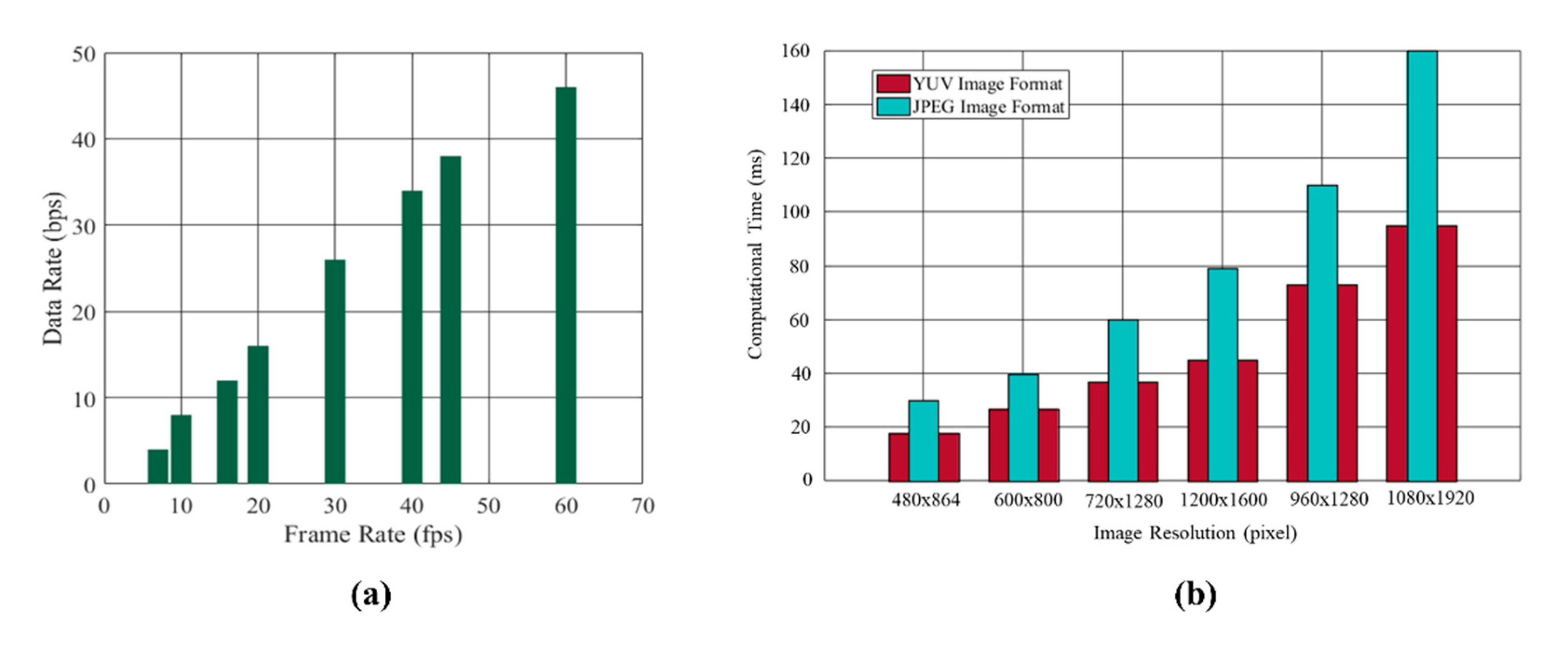
4.2.2. Image Sensor Communication Performance
4.2.3. Decoding Accuracy Rate Performance
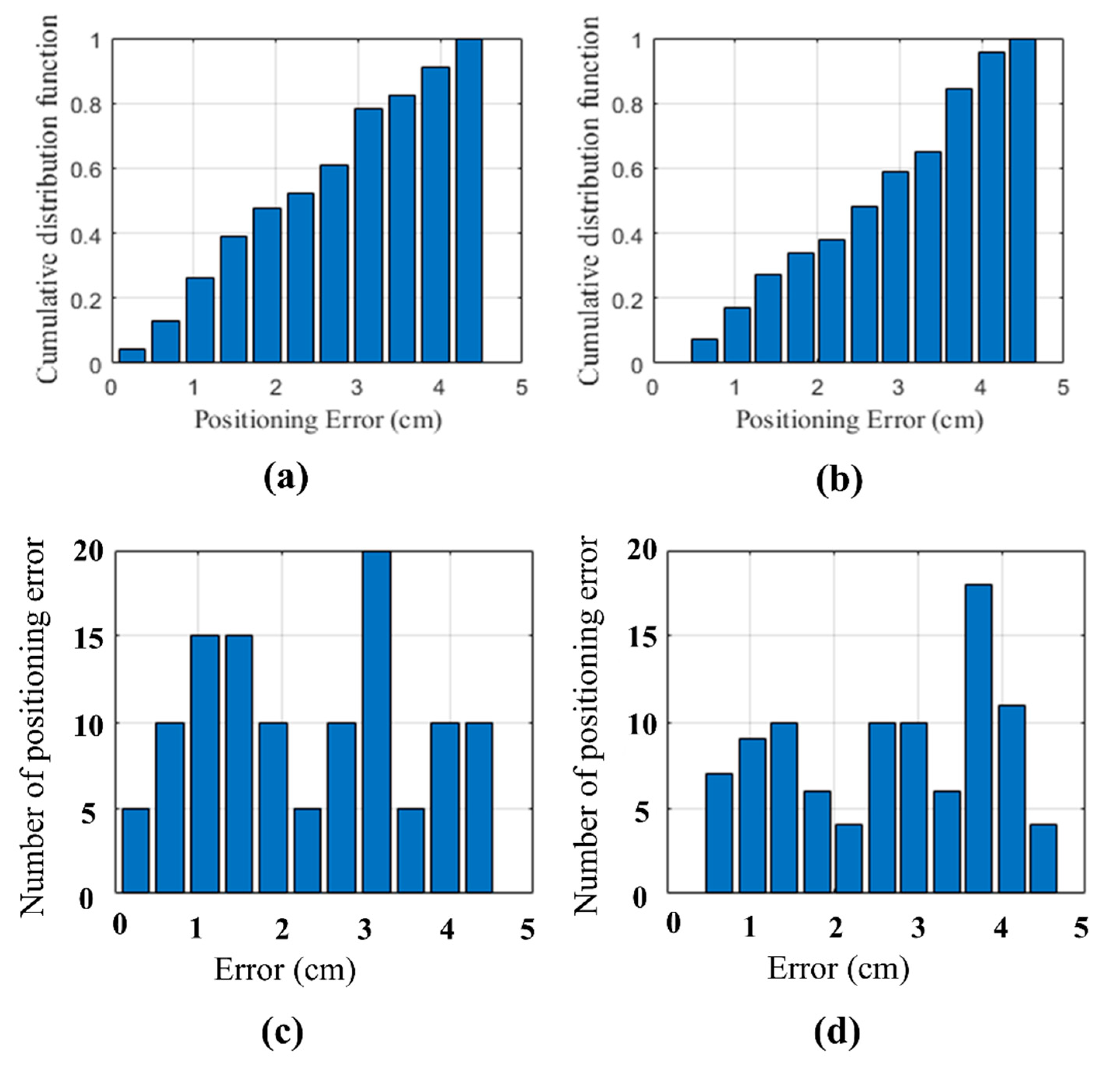
4.2.4. Positioning Performance Analysis
5. Conclusions
Author Contributions
Funding
Institutional Review Board Statement
Informed Consent Statement
Data Availability Statement
Conflicts of Interest
References
- Ozsoy, K.; Bozkurt, A.; Tekin, I. Indoor positioning based on global positioning system signals. Microw. Opt. Technol. Lett. 2013, 55, 1091–1097. [Google Scholar] [CrossRef] [Green Version]
- He, S.; Chan, S.H.G. Wi-Fi fingerprint-based indoor positioning: Recent advance and comparisons. IEEE Commun. Surv. Tuts. 2015, 18, 466–490. [Google Scholar] [CrossRef]
- Errington, A.F.C.; Daku, B.L.F.; Prugger, A.F. Initial position estimation using RFID tags: A least-squares approach. IEEE Trans. Instrum. Meas. 2010, 59, 2863–2869. [Google Scholar] [CrossRef]
- Cazzorla, A.; De Angelis, G.; Moschitta, A.; Dionigi, M.; Alimenti, F.; Carbone, P. A 5.6-GHz UWB position measurement system. IEEE Trans. Instrum. Meas. 2013, 62, 675–683. [Google Scholar] [CrossRef]
- Konings, D.; Bubel, A.; Alam, F.; Noble, F. Entity tracking within a Zigbee based smart home. In Proceedings of the 23rd International Conference on Mechatronics and Machine Vision in Practice M2VIP, Nanjing, China, 28–30 November 2016; pp. 1–6. [Google Scholar]
- Cifter, B.S.; Kadri, A.; Guvenc, I. Fundamental bounds on RSS-based wireless localization in passive UHF RFID systems 2015. In Proceedings of the IEEE Wireless Communications and Networking Conference (WCNC), New Orleans, LA, USA, 9–12 March 2015; pp. 1356–1361. [Google Scholar]
- Pham, N.Q.; Rachim, V.P.; Chung, W.-Y. High-accuracy VLC-based indoor positioning system using multi-level modulation. Opt. Express 2019, 27, 7568–7584. [Google Scholar] [CrossRef]
- Sejan, M.A.S.; Chung, W.-Y. Indoor fine particulate matter monitoring in a large area using bidirectional multihop VLC. IEEE Internet Things J. 2021, 8, 7214–7228. [Google Scholar] [CrossRef]
- Gu, W.; Zhang, W.; Kavehrad, M.; Feng, I. Three-dimensional light positioning algorithm with filtering techniques for indoor environments. Opt. Eng. 2014, 53, 107107. [Google Scholar] [CrossRef]
- Rajagopal, N.; Lazik, P.; Rowe, A. Visible light landmarks for mobile device. In Proceedings of the 3th IEEE/ACM International Conference on Information Processing in Sensor Networks (IPSN 2014), Berlin, Germany, 15–17 April 2014; pp. 249–260. [Google Scholar]
- Kuo, Y.-S.; Oannuto, P.; Hsiao, K.-J.; Dutta, P. Lusapose: Indoor positioning with mobile phones and visible light. In Proceedings of the 20th Annual International Conference on Mobile Computing and Networking, Maui, HI, USA, 7–11 December 2014; pp. 447–458. [Google Scholar]
- Yang, Z.; Wang, Z.; Zhang, J.; Huang, C.; Zhang, Q. Wearables can afford: Light-weight indoor positioning with visible light. In Proceedings of the 3th International Conference on Mobile Systems, Applications, and Services, Florence, Italy, 18–22 May 2015; pp. 317–330. [Google Scholar]
- Huang, H.; Feng, L.; Ni, G.; Yang, A. Indoor imaging visible light positioning with sampled sparse light source and mobile device. Chin. Opt. Lett. 2016, 14, 090602. [Google Scholar] [CrossRef]
- Hou, Y.; Xiao, S.; Bi, M.; Xue, Y.; Pan, W.; Hu, W. Single LED beacon-based 3-D indoor positioning using off-the-shelf device. IEEE Photonics J. 2016, 8, 1–11. [Google Scholar] [CrossRef]
- Kim, J.-Y.; Yang, S.-H.; Son, Y.-H.; Han, S.-K. High-resolution indoor positioning using light emitting diode visible light and camera image sensor. IET Optoelectron. 2016, 10, 184–192. [Google Scholar] [CrossRef]
- Zhu, B.; Cheng, J.; Wang, Y.; Yan, J.; Wang, J. Three-dimensional VLC positioning based on angle difference of arrival with arbitrary tilting angle of receiver. IEEE J. Sel. Areas Commun. 2018, 36, 8–22. [Google Scholar] [CrossRef]
- Ji, Y.; Xiao, C.; Gao, J.; Ni, J.; Cheng, H.; Zhang, P.; Sun, G. A single LED lamp positioning system based on CMOS camera and visible light communication. Opt. Commun. 2019, 443, 48–54. [Google Scholar] [CrossRef]
- Nakazawa, Y.; Makino, H.; Nishimori, K.; Wakatsuki, D.; Komagata, H. LED-tracking and ID-estimation for indoor positioning using visible light communication presented. In Proceedings of the 2014 International Conference on Indoor Positioning and Indoor Navigation (IPIN), Busan, Korea, 27–30 October 2014; pp. 87–94. [Google Scholar]
- Li, L.; Hu, P.; Peng, C.; Shen, G.; Zhao, F. Epsilon: A visible light based positioning system presented. In Proceedings of the 11th USENIX Conference on Networked Systems Design and Implementation, Seattle, WA, USA, 2–4 April 2014; pp. 331–343. [Google Scholar]
- Do, T.-H.; Yoo, M. TDOA-based indoor positioning using visible light. Photonic Netw. Commun. 2014, 27, 80–88. [Google Scholar] [CrossRef]
- Taparugssanagorn, A.; Siwamogsatham, S.; Pomalaza-Raez, C. A hexagonal coverage LED-ID indoor positioning based on TDOA with extended Kalman filter. In Proceedings of the 2013 IEEE 37th Annual Computer Software and Applications Conference, Kyoto, Japan, 22–26 July 2013; pp. 742–747. [Google Scholar]
- Rahman, M.S.; Haque, M.M.; Kim, K.-D. Indoor positioning by LED visible light communication and image sensors. Int. J. Elect. Comput. Eng. 2011, 1, 161. [Google Scholar] [CrossRef]
- Lin, B.; Ghassemlooy, Z.; Lin, C.; Tang, X.; Li, Y.; Zhang, S. An indoor visible light positioning system based on optical camera communications. IEEE Photon. Technol. Lett. 2017, 29, 579–582. [Google Scholar] [CrossRef]
- Bharati, S.; Rahman, M.A.; Podder, P. Implementation of ASK, FSK and PSK with BER vs. SNR comparison over AWGN channel. arXiv 2020, arXiv:2002.03601. [Google Scholar]
- Berman, S.M.; Greenhouse, D.S.; Bailey, I.L.; Clear, R.D.; Raasch, T.W. Human electroretinogram responses to video displays, fluorescent lighting, and other high frequency sources. Optom. Vis. Sci. 1991, 68, 645–662. [Google Scholar] [CrossRef]
- Liu, Y. Decoding mobile-phone image sensor rolling shutter effect for visible light communications. Opt. Eng. 2016, 55, 01603. [Google Scholar] [CrossRef]
- Chow, C.-W.; Shiu, R.-J.; Liu, Y.-C.; Yeh, C.-H. Non-flickering 100 m RGB visible light communication transmission based on a CMOS image sensor. Opt. Express 2018, 26, 7079–7084. [Google Scholar] [CrossRef]
- Yang, Y.; Nie, J.; Luo, J. ReflexCode: Coding with Superposed Reflection Light for LED-Camera Communication. In Proceedings of the 23rd Annual International Conference on Mobile Computing and Networking, Snowbird, UT, USA, 16–20 October 2017; pp. 193–205. [Google Scholar]
- Lee, H.Y.; Lin, H.M.; Wei, Y.L.; Wu, H.I.; Tsai, H.M.; Lin, K.C.J. RollingLight: Enabling line-of-sight light-to-camera communications. In Proceedings of the International Conference on Mobile Systems, Florence, Italy, 16–17 May 2015; pp. 167–180. [Google Scholar]
- Gutierrez-Martinez, J.-M.; Castillo-Martinez, A.; Medina-Merodio, J.-A.; Aguado-Delgado, J.; Martinez-Herraiz, J.-J. Smartphone as a light measurement tool: Case of study. Appl. Sci. 2017, 7, 616. [Google Scholar] [CrossRef]
- Zhang, R.; Zhong, W.-D.; Qian, K.; Wu, D. Image sensor based visible light positioning system with improved positioning algorithm. IEEE Access 2017, 5, 6087–6094. [Google Scholar] [CrossRef]
- Lee, J.-W.; Kim, S.-J.; Han, S.-K. 3D Visible light positioning by bokeh based optical intensity measurement in smartphone camera. IEEE Access 2019, 7, 91399–91406. [Google Scholar] [CrossRef]
- Quan, J.; Bai, B.; Jin, S.; Zhang, Y. Indoor positioning modeling by visible light communication and imaging. Chin. Opt. Lett. 2014, 12, 052201. [Google Scholar] [CrossRef]


| Parameters Name | Value |
|---|---|
| LED Model | BSDW-010, Color Temp. 5300~6000 K |
| LED Size | 15 cm |
| LED Power | 15 W |
| Number of LEDs | 6 |
| MCU | Atmega328p |
| MOSFET chip | P24N65E |
| Resistance R1 value | 10 kΩ |
| Resistance R2 value | 55 Ω |
| Frequency number | 8 |
| Synchronization frequency | 10 kHz |
| Error correction | Run-length encoding |
| Parameters Name | Value |
|---|---|
| Image Sensor | Rolling shutter CMOS sensor |
| Shutter speed | 16 kHz |
| ISO | 100 |
| Frame rate | 6 |
| MCU | 20 fps |
| Image processing library | OpenCV |
| Smartphone model | Samsung Galaxy S8 |
| Camera | Front Camera with 8 megapixels |
| Focal length | 24 mm |
| Aperture | 1.7 |
| Camera API | Camera 2 with API Level 23 |
| Camera image resolution | 600 × 800 pixels |
| Ref. | Positioning System | Experiment/Simulation | Experiment Testbed Size | Accuracy | Number of LEDs |
|---|---|---|---|---|---|
| [31] | Image | Experiment | 1.4 × 1.4 × 1.6 m | X:3 cm Y: 7 cm | 3 LEDs |
| [11] | AoA 1 + Triangulation | Experiment | 0.71× 0.74 × 2.26 m | 10 cm | 5 LEDs |
| [32] | AoA + Trilateration | Experiment | 1.0 × 1.0 × 2.4 m | <10 cm | 1 LED |
| [22] | RSS 1 + AoA | Simulation | 1.8 × 1.8 × 3.5 m | 15.6 cm | 4 LEDs |
| [33] | AoA + Image | Experiment | 1.8 × 1.8 × 3.5 m | <40 cm | 9 LEDs |
| Proposed | Image + Multilateration | Experiment | 2.5 × 4.5 × 2 m | 2.41 cm | 6 LEDs |
Publisher’s Note: MDPI stays neutral with regard to jurisdictional claims in published maps and institutional affiliations. |
© 2021 by the authors. Licensee MDPI, Basel, Switzerland. This article is an open access article distributed under the terms and conditions of the Creative Commons Attribution (CC BY) license (https://creativecommons.org/licenses/by/4.0/).
Share and Cite
Rahman, M.H.; Sejan, M.A.S.; Chung, W.-Y. Multilateration Approach for Wide Range Visible Light Indoor Positioning System Using Mobile CMOS Image Sensor. Appl. Sci. 2021, 11, 7308. https://doi.org/10.3390/app11167308
Rahman MH, Sejan MAS, Chung W-Y. Multilateration Approach for Wide Range Visible Light Indoor Positioning System Using Mobile CMOS Image Sensor. Applied Sciences. 2021; 11(16):7308. https://doi.org/10.3390/app11167308
Chicago/Turabian StyleRahman, Md Habibur, Mohammad Abrar Shakil Sejan, and Wan-Young Chung. 2021. "Multilateration Approach for Wide Range Visible Light Indoor Positioning System Using Mobile CMOS Image Sensor" Applied Sciences 11, no. 16: 7308. https://doi.org/10.3390/app11167308
APA StyleRahman, M. H., Sejan, M. A. S., & Chung, W.-Y. (2021). Multilateration Approach for Wide Range Visible Light Indoor Positioning System Using Mobile CMOS Image Sensor. Applied Sciences, 11(16), 7308. https://doi.org/10.3390/app11167308