Article

Large-Eddy Simulation Study of Flow and Heat Transfer in Swirling and Non-Swirling Impinging Jets on a Semi-Cylinder Concave Target

State Key Laboratory of Mechanical Manufacturing Systems Engineering, Xi’an Jiaotong University, Xi’an 710049, China
*
Author to whom correspondence should be addressed.
Appl. Sci. 2021, 11(15), 7167; https://doi.org/10.3390/app11157167
Submission received: 30 June 2021 / Revised: 28 July 2021 / Accepted: 1 August 2021 / Published: 3 August 2021
(This article belongs to the Section Mechanical Engineering)

Abstract

:
Swirling impinging jet (SIJ) is considered as an effective means to achieve uniform cooling at high heat transfer rates, and the complex flow structure and its mechanism of enhancing heat transfer have attracted much attention in recent years. The large eddy simulation (LES) technique is employed to analyze the flow fields of swirling and non-swirling impinging jet emanating from a hole with four spiral and straight grooves, respectively, at a relatively high Reynolds number (Re) of 16,000 and a small jet spacing of H/D = 2 on a concave surface with uniform heat flux. Firstly, this work analyzes two different sub-grid stress models, and LES with the wall-adapting local eddy-viscosity model (WALEM) is established for accurately predicting flow and heat transfer performance of SIJ on a flat surface. The complex flow field structures, spectral characteristics, time-averaged flow characteristics and heat transfer on the target surface for the swirling and non-swirling impinging jets are compared in detail using the established method. The results show that small-scale recirculation vortices near the wall change the nearby flow into an unstable microwave state, resulting in small-scale fluctuation of the local Nusselt number (Nu) of the wall. There is a stable recirculation vortex at the stagnation point of the target surface, and the axial and radial fluctuating speeds are consistent with the fluctuating wall temperature. With the increase in the radial radius away from the stagnation point, the main frequency of the fluctuation of wall temperature coincides with the main frequency of the fluctuation of radial fluctuating velocity at x/D = 0.5. Compared with 0° straight hole, 45° spiral hole has a larger fluctuating speed because of speed deflection, resulting in a larger turbulence intensity and a stronger air transport capacity. The heat transfer intensity of the 45° spiral hole on the target surface is slightly improved within 5–10%.

1. Introduction

An increase in hot gas inlet temperature is helpful for turbine efficiency improvement and energy-saving. The significantly curved leading edge bears the highest thermal load in turbine blades. Jet impingement has the maximum heat transfer rate among all the single-phase heat transfer processes. Therefore, when faced with a much higher cooling standard, a good choice is jet impingement cooling, which is widely used in the leading edge of blades. A lot of studies dealing with experimental and computational methods on fluid flow and heat transfer behavior of impinging jets on a concave surface have been reported in the literature. Harmon et al. [1] quantified the heat transfer characteristics of jet plates with different thicknesses for simulating the heat transfer in the leading edge of gas turbine blade. The results showed that the Nu changed slightly in the stagnation region of the target surface with different thicknesses. The contraction effect of the hole cavity can be minimized when the inlet of the jet is rounded, which causes a more symmetrical jet. Racetrack shaped jets can enhance heat transfer compared with round jets. Liu et al. [2] investigated the heat transfer mechanism of the impinging jet on a concave surface with Re = 12,000–20,000 and three different nozzle positions (E/d = 0, 0.5, and 1.0). Their results showed that heat transfer characteristics of tangential jet impact depended on Re and nozzle position. Zhou et al. [3] analyzed heat transfer performance of jets on concave target surfaces with different cooling hole diameters, including 0.4D, 0.6D, 0.8D, and 1.0D (D = 10 mm). Through evaluating and comparing moderate Re and Nu distribution, they found that heat transfer performance was largely determined by the diameter and location of the cooling holes. Qiu et al. [4] investigated the effect of different jet arrangements on a flow and heat transfer at Re= 10,000–40,000, a jet-to-target spacing of 1 and relative surface curvature of 10. They pointed out that both inline and staggered cases could enhance heat transfer uniformity compared with the array jet. Curved surface-averaged Nu increased when the jet-to-jet spacing was in an inline arrangement. Singh and Prasad [5] applied a new structure of jet cooling in the leading edge of gas turbine blade. They studied the effect of concave target surfaces with different curvature radiuses on cooling performance.
In the available reported studies, most of the nozzles used in impinging jets on a concave surface are the conventional smooth circular holes or slots with non-swirling case, while the common features of impinging jets issuing from the conventional holes/slots include very high local convective heat transfer at the stagnation point and a rapid decay of heat transfer along the radial direction on the target wall. That is, conventional impinging jets induce a non-uniform radial heat transfer, leading to a non-uniform temperature distribution along the target surface. At the same time, the curved configuration of the leading edge exacerbates the non-uniform heat transfer. The thermal stress caused by temperature differences is high enough to cause structural damage, which weakens device security. Therefore, it is essential to develop a new cooling method that can not only enhance heat transfer, but also make a more uniform cooling on the target surface. Liu et al. [6] analyzed the cooling performance of the cooling chamber of the leading edge of a gas turbine. They found the swirling flow existing in the cooling chamber could improve the cooling efficiency, and a larger ratio of swirl chamber radius to jet slot height and a larger Reynolds number could enhance the cooling performance on the leading edge of a gas turbine, though the pressure loss of the swirl chamber is increased. Lin et al. [7] enhanced heat transfer performance using the double swirl chambers (DSC) cooling technology with multiple in-line nozzles in the leading edge of gas turbine blades to, as the special configuration can, produce two anti-rotation swirls. Compared with traditional impingement cooling, the new cooling method can provide more uniform heat transfer distribution and a higher heat transfer rate in the axial chamber. A better globally averaged thermal performance coefficient can be obtained with the new cooling technology when inlet slots and Re are the same. Zhou et al. [8] investigated the effect of channel shape on the cooling performance of DSC technology using five double swirl channels formed by two overlapping elliptic cylinders with different length ratios between the vertical and the horizontal semi-axis. The results showed that the largest length ratio between the vertical and the horizontal semi-axis of the target channel produced the lowest flow loss, largest averaged Nu and best heat transfer performance. Heat transfer distribution on the target surface becomes more uniform with the length ratio decreasing. The enhancements of the maximum overall averaged Nu and heat transfer performance with DSC are about 30% and 33%, respectively. The studies mentioned above indicate that swirling flow in the cooling chamber in the leading edge can improve the cooling effect, which sets a clear direction for future research. Compared with the complex swirling flow chamber, a special jet nozzle is relatively simple to generate swirling flow. The application of swirl, i.e., superimposition of a circumferential or tangential velocity component to the axial jet flow, can markedly affect the flow and turbulence characteristics of a jet. Compared with the conventional non-swirling case, the swirling jet spreads more rapidly and widely, and entrains the surrounding fluid at a greater rate. Thus, the growth rate of turbulence intensity is higher, and the mean velocity decays more rapidly. Under the comprehensive effect of turbulence intensity and velocity decay, the heat transfer coefficient on the target surface may be enhanced or weakened according to the swirl element.
In recent years, different inserts have been introduced to generate swirling jets and generally include a screw rod, twisted tapes/strips, or a guide vane inside a nozzle which can form a swirl element. Fenot et al. [9] employed a screw rod with eight narrow channels with an angle of θ = 0° or 21°. They observed that the presence of an insert modified the flow and increased the Nu values in comparison with classical round jet flow only for a small nozzle-to-plate distance. Using a twisted belt as a flow guiding element, Nanan et al. [10,11] compared the heat transfer characteristics between the swirling impinging jet and the round hole jet with the twisted rate y/w = 3–6, H/D = 2–8, and Re = 4000–16,000. Under the condition of a small H/D with large y/w and Re, the Nu of the target surface reached the maximum, and the coefficient of heat transfer of the rotating jet was higher than that of the round hole jet; however, when H/D was large, the result reversed. With a twisted strip used to generate the swirling flow, Nuntadusit et al. [12] investigated the flow and heat transfer enhancement mechanism of a swirling impinging jet array with H/D = 4, Re = 20,000, and S = 0–0.94. They found that as the swirling number increased, the jet dispersion became larger. Compared with the traditional round hole jet, the heat transfer of the swirling jet was enhanced at S = 0.4; the intensity of heat transfer was weakened at a large swirling number, i.e., S = 0.78 and S = 0.94. Our research group [13,14] recently reported a threaded nozzle, which generated swirling flow and enhanced heat transfer performance of impinging jets under the vertical and inclined conditions compared with the conventional round hole. Our proposed nozzle consisted of a smooth circular hole and four circumferential screw grooves for structuring the impinging jet flow with a superimposed swirl, so that the nozzle was similar to the conventional circular hole with internal threads. The non-dimensional swirl number of the swirling jet at the nozzle exit was about 0.18, and the excited flow belonged to a low-intensity swirling flow. With 3D printing technology, the traditional circular holes will be easily replaced with these threaded holes for the leading-edge cooling of turbine blades.
Among the swirling impinging jet studies in the literature, research on heat transfer performance on a concave surface has not been reported. A typical impinging jet consists of various complex flow regions, such as free jet, stagnation, streamline curvature, and wall jets, and these complexities make it difficult for Reynolds-averaged Navier–Stokes (RANS) equation-based turbulence models to accurately predict fluid flow and thermal behaviors in an impinging jet. The swirling flow in jets and the curved concave surface substantially broaden and deepen the complexity of the flow phenomena compared with the typical impinging jet. Recently, some studies on swirling impinging jets on a flat surface using large eddy simulation (LES) have been reported. Uddin et al. [15] investigated the swirling impinging jet issuing from a guide vane on a flat surface using LES. They found that the heat transfer performance of the nozzle with the insert was better than that of the ordinary nozzle; however, it led to higher pressure loss to some extent.
It is noted that there is a lack of proper fluid flow and heat transfer data for swirling jet impingement in the stagnation region as well as the wall jet region for a curved concave target. Such data will be useful to improve the understanding of fluid flow and heat transfer behavior in these regions. The aim of the present study is to perform LES of a swirling impinging jet flow issuing from a threaded hole on a semi-cylinder concave target at Re = 16,000 and H/D = 2. In this work, we firstly presented the detailed governing equations and analyzed the simulated results of a swirling impinging jet on a flat surface using two different turbulence subgrid-scale stress models; then, we described the computational domain of the present problem, including the swirling and non-swirling impinging jet on a semi-cylinder concave target; finally, we discussed the flow features, spectral characteristics, heat transfer, and frequency characteristics obtained. This study compared flow and heat transfer performance of the swirling and non-swirling impinging jet on a semi-cylinder concave target. Using LES computations, this study may help to understand the physical phenomena involved in the formation, development, and decay of the swirling impinging jet on a concave target.

2. Governing Equations and Subgrid-Scale Stress Modeling of LES

2.1. Governing Equations

All the flow variables are decomposed into a filtered (or resolved) and unresolved (or subgrid scale, SGS) components by applying a spatial filter in LES. Therefore, a variable which can represent pressure, temperature, or velocity is divided into φ ¯ (resolved) and φ ˜ (subgrid) components, that is, φ =   φ ¯ + φ ˜ . Spatial filtering is performed on the Navier–Stokes equations by applying a low-pass filter.
φ ¯ x , t = G x , x φ x , t d x
where x is the space coordinates, x denotes dummy space coordinates for each grid cell, and t is the time coordinate. G is the low-pass filter, and in this paper a top-hat filter is used. Which is defined as
G x , x   =   1 Δ 3 x x     1 2 Δ 0 x x > 1 2 Δ
where, Δ = V 1 3 = Δ x Δ y Δ z 1 3 ,     Δ denotes the characteristic filter width. By applying a filter G to the incompressible Navier–Stokes equations and by neglecting the body forces, the following equations can be obtained.
u ¯ i x i = 0
ρ u ¯ i t + ρ u ¯ i u ¯ j x j = p ¯ x i + x j μ u ¯ i x j + u ¯ j x i τ i j S G S x j
T ¯ t + u ¯ j T ¯ x j = x j [ Γ T ¯ x j ] q j S G S x j
where the variables with an overbar represent the filtered (the locally averaged) values. Here, u i ,   p   and   T denote fluid velocity, pressure and temperature, respectively.   ρ ,   μ   and   Γ ( = λ ρ c p ) represent density, dynamic viscosity, and the thermal diffusivity of air, respectively. λ   and   c p are thermal conductivity and the specific heat of air, respectively.
Using the eddy viscosity hypothesis, the subgrid stresses τ i j S G S can be described as
τ i j S G S = ρ u i u j ¯ u i ¯ u j ¯ = 2 μ t S ¯ i j + 1 3 τ k k S G S δ i j
where,   τ k k S G S is the isotropic part of the subgid scale stresses and can be added to the filtered pressure or simply neglected for incompressible flow [16]. δ i j denotes the Kronecker delta. S ¯ i j represents the strain rate tensor for the resolved scale, which is defined as
S ¯ i j = 1 2 u ¯ i x j + u ¯ j x i
In the most basic SGS model (namely the Smagorinsky model), μ t is a product of a length scale and a velocity scale, can be expressed as
μ t = ρ L s 2 2 S ¯ i j S ¯ i j
L s is calculated using
L s = min k l , C s Δ
where k is the Von Karman constant, l is the distance closest to the wall. C s is an arbitrary constant, which has to be provided as an input.
The Smagorinsky model needs specification of a value of the constant C s and this limits its applicability to various complex problems. When C s is set to the default value of 0.13 in the standard Smagorinsky model, it found that the subgrid dissipation is excessively high, generally resulting in a substantial underprediction of the jet width [17]. However, when C s is specified to 0.12, it is too dissipative and predicts incorrect asymptotic behavior near a wall or in laminar zones and overpredicts the length of the potential core [18]. Furthermore, it does not allow possible subgrid scale energy backscatter to the resolved scales [19]. To overcome the limitations, other SGS models have been developed. Germano et al. [20] and Lilly [21] proposed a dynamic Smagorinsky-Lilly model (DSLM); C s can be calculated at each time step by double filtering of the flow variables. The DSLM can show the correct asymptotic behavior near the walls and in laminar regions and does not formally prohibit possible energy backscatter. A coefficient C d , which is dynamically computed, replaces the square of C s and depends on the local flow structure. In order to compute Cd, a test filter denoted by a hat and of width larger than the grid filter is introduced. The dynamic constant C d is calculated with a least-squares approach according to:
C d = L i j 1 3 L k k δ i j M i j M i j .
Here, L i j = u i ¯ u j ¯ ^ u i ¯ ^ u j ¯ ^ , M i j = 2 Δ ^ 2 ( S ¯ ^ S ¯ ij ^ S ¯ ^ S ¯ ij ,   and   S ¯ = 2 S ¯ i j S ¯ i j .   C d is a local and instantaneous quantity and thus can vary widely in time and space. However, when C d is a negative value, the simulated property may lead to numerical instabilities, and it generates instabilities in the field. Furthermore, if the total viscosity (μ+ μ t ) is negative, the subgrid eddy viscosity μ t is generally clipped to zero. The test filter used in the DSLM is a symmetric discrete filter based on the trapezoidal rule:
f i ^ = 1 4 f i 1 + 2 f i + f i + 1
Overall, the DSLM which overcomes some of the drawbacks of the Smagorinsky model is a suitable alternative. However, it generates instabilities in the field, which need to be overcome. Subsequently, Nicoud et al. [22] proposed a wall-adapting eddy viscosity model (WALE); the expression for the subgrid-scale eddy viscosity is changed so as to automatically take care of the zero value at the wall. In the WALE, the subgrid eddy viscosity μ t is defined by
μ t = ρ L s 2 ( S i j d S i j d ) 2 3 ( S ¯ i j S ¯ i j ) 2 5 + ( S i j d S i j d ) 4 5
Here, S i j d = 1 2 g ¯ i j 2 + g ¯ j i 2 1 3 g ¯ k k 2 δ i j ,   g ¯ i j = u ¯ i x j , L s = min k l , C W Δ , and C W is 0.325 as the default value and has been found to yield satisfactory results for a wide range of flow. With this spatial operator, the WALE is designed to return the correct wall asymptotic behavior for wall bounded flows. In the present study, the DSLM and WALE are employed because both of them have been demonstrated in the literature to predict impingement flow more accurately [23].
The turbulent sub-grid scale heat flux q j S G S is modeled using a standard gradient diffusion model.
q j S G S = Γ t T ¯ x j = ν t P r t T ¯ x j
Here,   Γ t ,   ν t ,   and   P r t are the sub-grid scale thermal diffusivity, kinematic viscosity, and Prandtl number, respectively. In the dynamic models, the subgrid-scale turbulent Prandtl number or Schmidt number is obtained by applying the dynamic procedure originally proposed by Germano et al. [20] to the subgrid-scale flux. The system of equations and subgrid models is solved numerically by the commercial code Fluent 16.0 [24].

2.2. The Selection of the DSLM and WALE Models

DSLM and WALEM are used to simulate the test configuration with the swirl number S = 0.2 reported by Ianiro and Cardone [25]. In ref. [25], the swirl flow is generated by means of a helical insert and the swirl number is computed according to the formula
S = 2 3 [ 1 D 1 / D 3 1 D 1 / D 2 ] t a n θ
where D and D 1 are nozzle and vane pack hub diameters, respectively, and θ is the swirling angle. The swirling jet has both tangential and axial velocity components compared with the conventional non-swirling jet. The combination of tangential and axial velocities enhances jet turbulent intensity, and hence it is deemed to have different swirling intensities and correspondingly different jet flow field characteristics. Thus far, lots of new nozzles with (intrusive) geometric inserts or directly guiding tangential flow have been proposed to excite the swirling jet [26], and then there have been no unified understanding of the flow mechanism and flow characteristics of swirling impinging jets (SIJ), and further studies are needed.
Figure 1a shows the schematic of the computational domain. Here, the radial radius of the flat target surface is ten times the internal diameter of the cylindrical nozzle (D = 19.7 mm) with a helical insert as swirl generator. The jet spacing (H) from the nozzle exit to the flat target is 2D and the height of jet space is 2.5D. The total height of the nozzle is 6.5D with a smooth section of 2D and an internal helical section of 4.5D. The swirl flow is generated by a helical insert and the swirl number is 0.2. It is noted that the internal helical section is extended to jet space and the length is 0.5D. The multi-block structured grid is drawn by applying the meshing software of ICEM CFD 17.0 as shown in Figure 1b. In order to accurately capture the flow fields near the wall, the interface region of the jet space is chosen as a focus domain using a structured and refined grid above the target surface. The size of the first layer near the wall is 0.075 mm with the grid growth rate of 1.07, and the value of the y+ function is about 0.5. The results of the grid-independent tests show that the suitable grid density is about 20.55 million cells. The length × width × height of the grid node numbers for the three-dimensional jet space is 142 × 145 × 142.
At the nozzle inflow, a mean velocity is specified as the constant value of inlet mean velocity based on a given Re = 28,000 ( U b = R e ν / D = 22.436 m/s, D = 19.7 mm; ν is the kinematic viscosity of air at the jet exit). No fluctuations are added to this inflow; therefore, instantaneous velocities at this inflow are set equal to its mean velocities. For the solution of the energy equation, inflow temperature is set to 25 °C at the nozzle inlet to ensure a real ambient temperature condition. The top surface of the jet space is considered to be the inlet boundary of ambient airflow with a pressure of 1atm and a temperature of 25 °C. The flat target is set as a non-slip surface with constant heat flux of 1000 W/m2, and the nozzle walls are modeled as adiabatic walls with a non-slip boundary. Four edges of the jet space are modeled as the outlet boundary with the atmospheric pressure of 1atm.
Herein, the commercial software of ANSYS FLUENT 16.0 is used for calculation. The iterative algorithm of the fractional step method is used in the calculation process using the NITA scheme (i.e., the Non-Iterative Time Advancement option), and all the governing equations are time marched using a second-order with the accurate time-stepping scheme. The non-dimensional time step (△tUb/D) is set to 1.024 × 10⁻³ for keeping the Courant number less than 1. After the flow reaches a statistically steady state, the statistics are calculated for 100 non-dimensional time units. The volume-averaged resolved kinetic energy is monitored and reaches a stationary state in approximately 60–70 non-dimensional time units, and the flow is computed for 100 non-dimensional time units before starting the data sampling for statistics.
Figure 2 shows wall-normal distribution of the mean radial velocity and turbulent energy at r/D=2. As depicted in Figure 2, the velocity is similar for the two turbulence models, while the turbulent kinetic energy at y/D ≤ 0.16 is different. The change trend of turbulent kinetic energy near the wall for the WALEM is almost closed to that of the velocity in the wall boundary layer, which indicates that the WALEM can capture the fluctuating velocity near the wall given by the turbulent kinetic energy.
According to the criteria presented by Celik et al. [27], when the index s = ˜ 1 1 + ν / ν t is equal to 1, it is not sensitive to grid resolution since it is anticipated that ν t ν in most LES applications. That is, the LES is better resolved as the value of ν t / ν is smaller. Celik et al. [27] suggested that LES is considered to be good if the index of quality ( LESIQ ν = 1 1 + 0.05 1 + ν t / ν 0.53 ) is greater than 0.8. Figure 3 shows the wall-normal distribution for the ratio of the sub-grid viscosity to the molecular viscosity at r/D = 0 and r/D = 1. It is found that the index of LESIQ ν varies between 0.933 and 0.952 for the two turbulence models and the WALEM have littler ν t / ν near the wall compared to the DSLM.
The Nu distribution is predicted by LES with the WALEM and DSLM and compared with the experimental data of Ianiro and Cardone [25], as shown in Figure 4. The global trend and variation are well captured for both the WALEM and DSLM. It is clearly seen in Figure 4 that an increase in Nu in region of r/D = 0–0.75 and a fast decay in the region after r/D = 0.75 are captured by the present LES simulations. The numerical results using WALEM agree better with the experimental results than those using the DSLM, especially the predicted peak at r/D = 0.75. However, the LES results using WALEM under-predict the experimental values at r/D < 0.25, about 18%, while the computed results using WALEM under-predict the experimental values at r/D > 0.5, about 7%. The big discrepancy exists between the predicted and experimental values in this region of r/D < 0.25, which may be explained by the fictitious zero value of subgrid-scale eddy viscosity in the near-wall boundary layer at this region, shown as Figure 3. Receiving an accurate simulation for large lumps of stagnant airflow near the stagnation point is still a big challenge in the computation of impinging flows at high Reynolds number values using the LES [23]. Furthermore, the experimental results reported by ref. [25] have measurement errors of less than 3%. Therefore, WALEM is more suitable for LES of swirling impinging jet flow in jet space and is selected in the following simulations.

3. Problem Description and Computational Setup

Figure 5a shows the geometry of the thread-like hole with a helical angle of 45°, and the jet including the swirl component is referred to as SIJ. The swirling impinging jet issuing from the 45° spiral hole is a weak swirling flow with a swirling number of about 0.18 according to the computed result in ref. [13]. When the groove angle is 0°, the flow grooves are straight, and the jet is called a multi-channel impinging jet (MCIJ) with a non-swirling case. In ref. [13], our team found that all the values of Nu(r) for SIJ (θ > 0) with a high heat transfer rate are bigger than those for MCIJ (θ = 0) in the region of r/dj ≤ 0.5 at the same cases. The new proposed nozzle to excite the swirling flow can enhance heat transfer radial uniformity compared to the MCIJ. In ref. [26], the experimental data shows that heat transfer on the flat target surface for the new nozzle with θ = 45° can be enhanced on the whole target surface compared with the MCIJ and CIJ. For the MCIJ, the flow feature is different for that of the CIJ, and the heat transfer on the flat target surface is comparable to that of the SIJ [25,26]. When the target surface becomes concave, the jet flow field for the MCIJ and SIJ is more complex, and heat transfer on a semi-cylinder concave target for these new nozzles may be more interesting. Herein, the groove angles of 0°and 45°are chosen to study the flow and heat transfer characteristics of the non-swirling and swirling impinging jets on a concave target.
Figure 5b shows the geometry of the computational domains. The inner diameter of the semi-cylinder concave target is 27 mm with a radial length of 84 mm. Figure 5c shows the multi-block structured grid model, and to ensure high quality and consistency, the grid setting is the same as that of Figure 1b. The size of the first layer near the wall is 0.075 mm with a grid growth rate of 1.07, and the value of the y+ function is also about 0.5. The result of the grid-independent tests shows that the suitable grid density is about 12.86 million cells with a maximum cell feature length of 0.3 mm.
The computational setup for the jets on the concave target remained fairly consistent with the above verified case for the jets on the flat target mentioned in Section 2.2. The difference is just the mean velocity profile at the nozzle inflow, which is specified based on the given Re = 16,000 with an equivalent diameter of 6 mm. Related to the inflow velocity and the equivalent diameter, the non-dimensional time step is changed to 5.76 × 10⁻⁴ to keep the Courant number less than 1. Similarly, the statistics are calculated as the same as the above verified case.

4. Results and Analysis

4.1. Flow Field Analysis

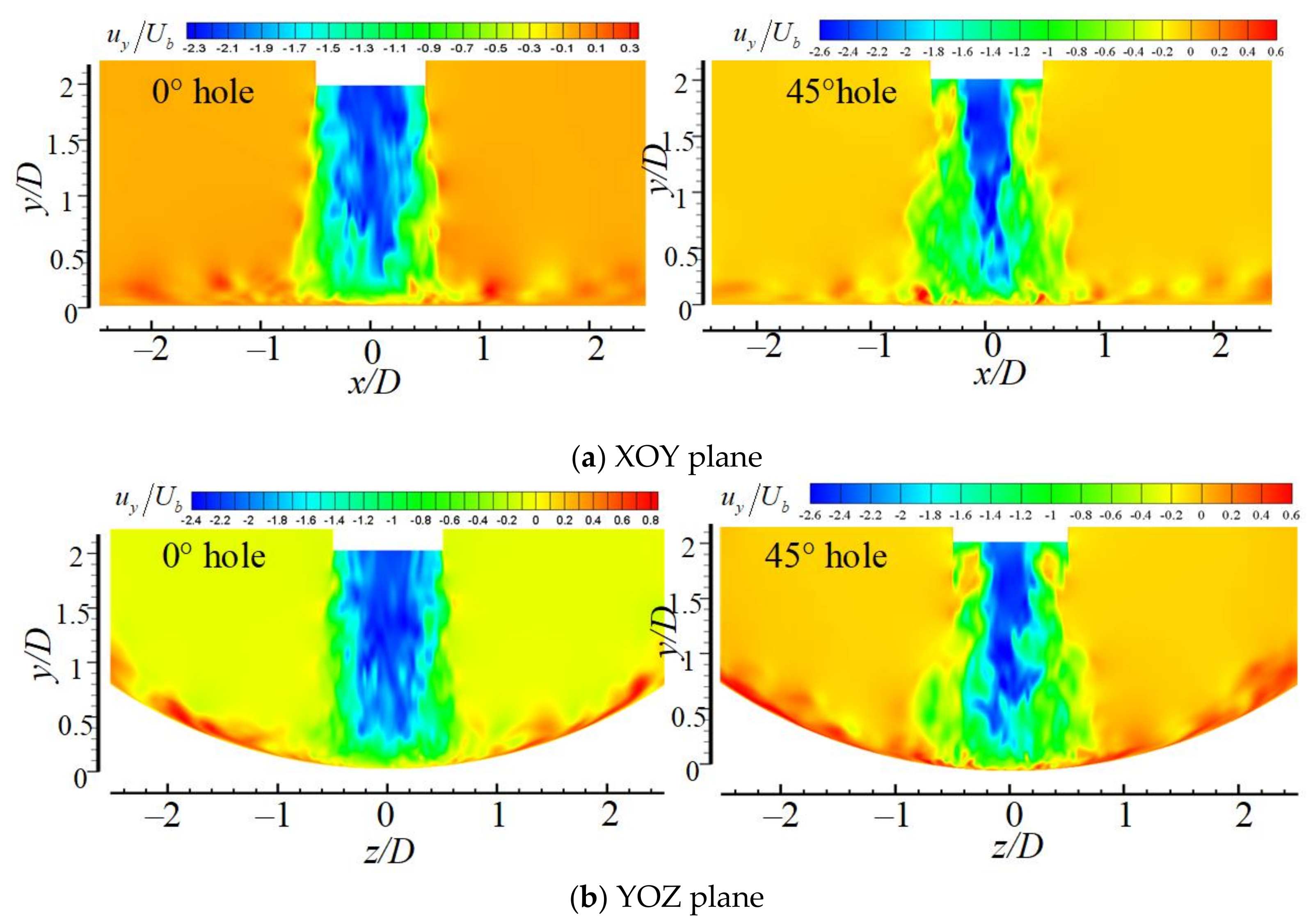
Figure 6 shows the contours of the instantaneous axial velocity in non-swirling and swirling turbulent impinging jets in the XOY and YOZ planes. Compared with the MCIJ, SIJ has a larger obstruction effect on the jet flow due to the spiral channels. Most of the jet is collected in the central region of the nozzle, resulting in a larger axial velocity of the potential flow core in the jet space for the 45° spiral nozzle. Due to the effect of the swirl on the jets, it can also be seen that SIJ has a large tangential velocity and the effect to entrain the surrounding low-speed airflow is stronger, while the entraining airflow from the top of the jet space is higher. Under the action of the processing vortices, the entraining airflow is rapidly mixed with the potential flow, so that the jet with high speed under the nozzle exit, the blue region shown in Figure 6b, becomes gradually weak, which decays more rapidly along the flow direction. At the periphery of the potential flow, the mixed airflow forms the “skirt type” green region with a larger diffusion area. For the MCIJ issuing from the 0° straight nozzle, the injected groove velocity is slightly lower than that at the central region of the nozzle due to the effect of the wall boundary layer, while it has a longer potential flow in the jet space and forms a “taper-foot-type” green region with a relatively smaller diffusion area compared with the SIJ. After the jet impacts the concave target, the rebound axial velocity from the wall free jet in the YOZ plane (uy/Ub = 0.8) is much larger than that in the XOY plane (uy/Ub = 0.3) due to flow delay on the curved surface for the MCIJ, while the rebound axial velocities in the XOY and YOZ planes (uy/Ub = 0.6) are comparable due to the entrainment effect of the velocity component of the swirl. Therefore, it can be inferred from the flow phenomenon that the swirl flow by the 45° spiral nozzle struggles more to escape from the curved and flat surfaces. As a result, the cooling effect may be improved on the curved surface with a more uniform heat transfer. It is worth noting that the range of legend values in Figure 6 is the actual range of solution values. Even though the color is the same, the value is not the same.
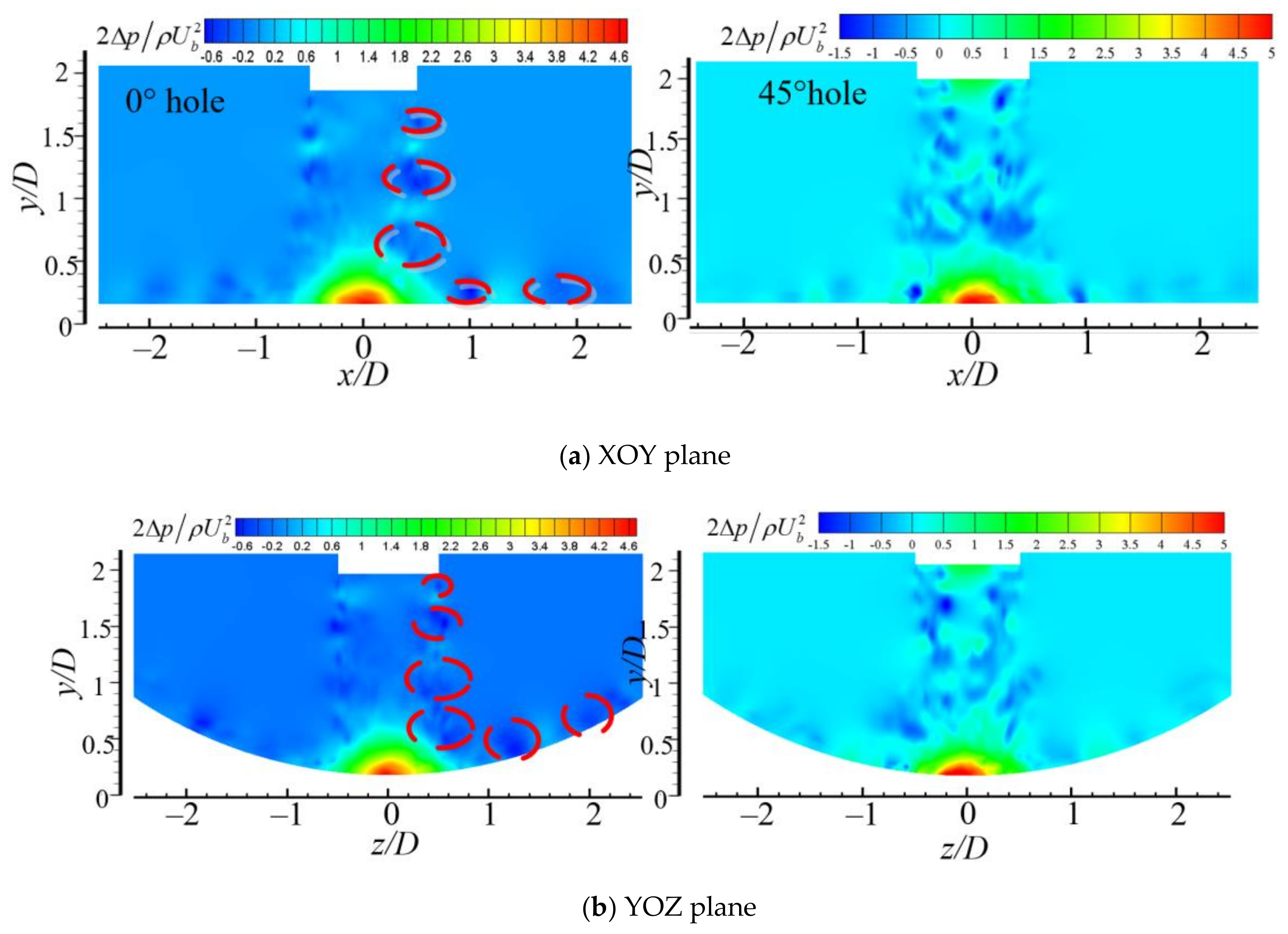
Figure 7 shows the distribution of pressure in the XOY and YOZ planes. For the MCIJ, there are a series of blue regions with negative pressure (marked in red circle) around the potential flow, which are generated from Kelvin–Helmholtz instability in the shear layer, resulting in a series of vortex pairs. Under the entrainment effect of the airflow in the free shear layer, the jet in the stagnation zone deflects quickly, escapes outward in the radial direction, forms wall free jet at about x/D = 1 with the negative pressure in the blue region near the wall, and tends to gradually entrain the low-speed ambient gas above the wall. The secondary blue region near the wall occurs at x/D = 1.8, where the escaped airflow with the dominant radial velocity meets with the entrained ambient gas from the outlet. For the SIJ, there are not any vortex pairs in the jet space, and many blue regions of high negative pressure with a small scale are distributed disorderly throughout the whole downstream flow of the nozzle. It indicates that the addition of tangential velocity resulted in a more complex entrainment mixing jet. Accordingly, many small-scale complex vortices form and distribute anywhere around the central-jet impinging zone. A peak of high negative pressure near the wall at x/D = 0.8 can be seen in the XOY plane, which indicates that the wall-free jet at that position is more intense than that of the non-swirling jet. Compared with the MCIJ, the red region of high positive pressure in the stagnation zone for the SIJ is bigger, which is attributed to the potential flow in the central region developing closer to the target surface. It is worth noting that the range of legend values in Figure 7 is the actual range of solution values. Even though the color is the same, the value is not the same.
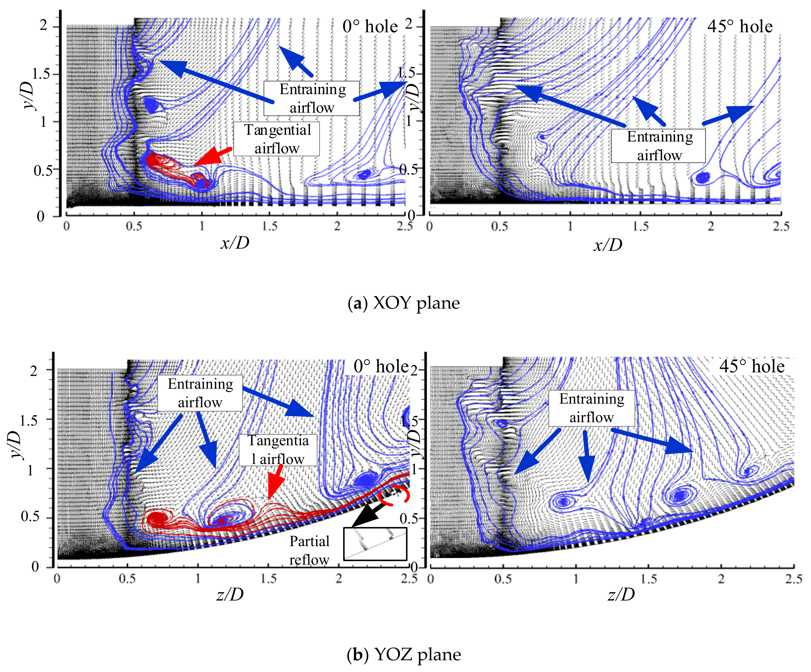
Figure 8 shows the streamlines and velocity vectors in the XOY and YOZ planes. For the MCIJ, the surrounding airflow from the top of jet space is carried by the free shear layer, moving downstream to the target surface with some vortex pairs, and deflecting to the radial direction at x/D = 0.5–0.8 with a similar corner vortex. When the jet impinges the stagnation point, the rebounded airflow near the wall also deflects to the radial direction and meets the shear tangential flow (marked red curves), which results in a large-scale recirculation vortex at about x/D = 1 in the XOY plane. A similar vortex occurs at z/D = 1.25 in the YOZ plane due to the hamper effect of the curved cylinder concave target on the rebounded tangential airflow. It should be noted that the recirculation vortices produce a certain suppression on the deflected airflow in the stagnation zone to escape along the radial direction, which would weaken the heat transfer in this region to some extent. In the range of x/D = 1–1.5, the escaped velocity near the wall gradually increases and the entrainment effect of shear flow above the wall also gradually enhances. In the range of x/D = 1.5 away from the stagnation point, the escaped airflow near the wall would hold steady. However, shear flow meets the entrained airflow from the outlet, resulting in a large-scale recirculation vortex at x/D = 2.3 near the exit of jet space. Indeed, the discharge capacity of axial flow along the wall would be suppressed by the vortex, and heat transfer would be the same. For the SIJ, the potential flow in the central region has a bigger axial velocity, and the airflow of the free shear layer around the potential flow has a stronger entrainment effect on the surrounding gas. It can be seen that lots of marked blue oblique curves of entrainment flow come from the top of jet space. Compared with the non-swirling case, these curves are denser without any large-scale vortex. At the same time, there is no obvious flow structure of vortex pairs around the potential flow, and no complicated similar corner vortex in the range of x/D = 0.5–0.8 in the XOY plane. These disappeared large-scale vortices may be attributed to tangential velocity of the swirl jet. The escaped airflow near the wall in the XOY plane has a higher radial velocity, resulting in a stronger shear flow. It shows that the whole recirculation vortex appears earlier at x/D = 2 and a large-scale semi-vortex follows downstream near the exit. Three obvious vortices above the concave wall form in the YOZ plane as shear flow meets with the entrained airflow from the top of jet space. It can be seen that the positions of vortex center are at z/D = 0.7, 1.2, and 2.3 for the MCIJ, while these positions are at z/D = 0.9, 1.8, and 2.3 for SIJ. Two upstream vortices for the SIJ are not only further from the stagnation point, but also higher above the wall compared with the MCIJ. Moreover, for the MCIJ, one more unformed recirculation vortex appears near the exit except three vortices. It should be pointed out that these different flow structures for the SIJ would be beneficial to improve heat transfer on the semi-cylinder concave surface.
Figure 9 shows the instantaneous Q-criterion. Jeong et al. [28] proposed the Q-criterion based on the positive second invariant of velocity gradient or the complex eigenvalues of velocity gradient; their definition can accurately identify the vortex core in flows where the vortex geometry is intuitively clear. The value of Q is the second invariant and is defined as
Q = Ω i j Ω i j S i j S i j / 2
where S i j   and   Ω i j are the symmetric and antisymmetric components of velocity gradient, i.e., S i j = 1 2 u i x j + u j x i ,   Ω i j = 1 2 u i x j u j x i . Thus, Q represents the local balance between shear strain rate and vorticity magnitude. Then, Q is dimensionless as:
Q c = Q D 2 / U b 2
The flow in the free shear layer gradually forms lots of small-scale vortices, and some of these vortices develop, grow up, and come together, and at last the vortex rings form. The vortex ring may also continue growing and linking up into a large-scale vortex ring. For the MCIJ, small-scale vortex rings in the green region around the potential flow have a small diffusion area, and four large-scale blue vortex rings near the wall distribute in four directions, corresponding to the corners of four straight grooves. As the target is a semi-cylinder concave surface, the discharge capacity for the MCIJ is different. It can be seen that two of the four large-scale blue vortex rings are big, and the other two are small. Small-scale vortex rings are relatively sparse among these large vortex rings. For the SIJ, many moderate-scale vortex rings in the green region around the potential flow have a big diffusion area, and large-scale blue vortex rings near the wall evenly distribute and link into a circle. It can be inferred that the airflow near the wall escapes mainly along four corners for the MCIJ, while the airflow escapes evenly all around for the SIJ.
Jet flow enters the region of vortex agglomeration around a dimensionless height y/D = 0.6–0.8, and then at the downstream area at about y/D = 0.25, the escaped flow enters the region of vortex stretching and deformation near the target surface, and the large vortex ring appears. 
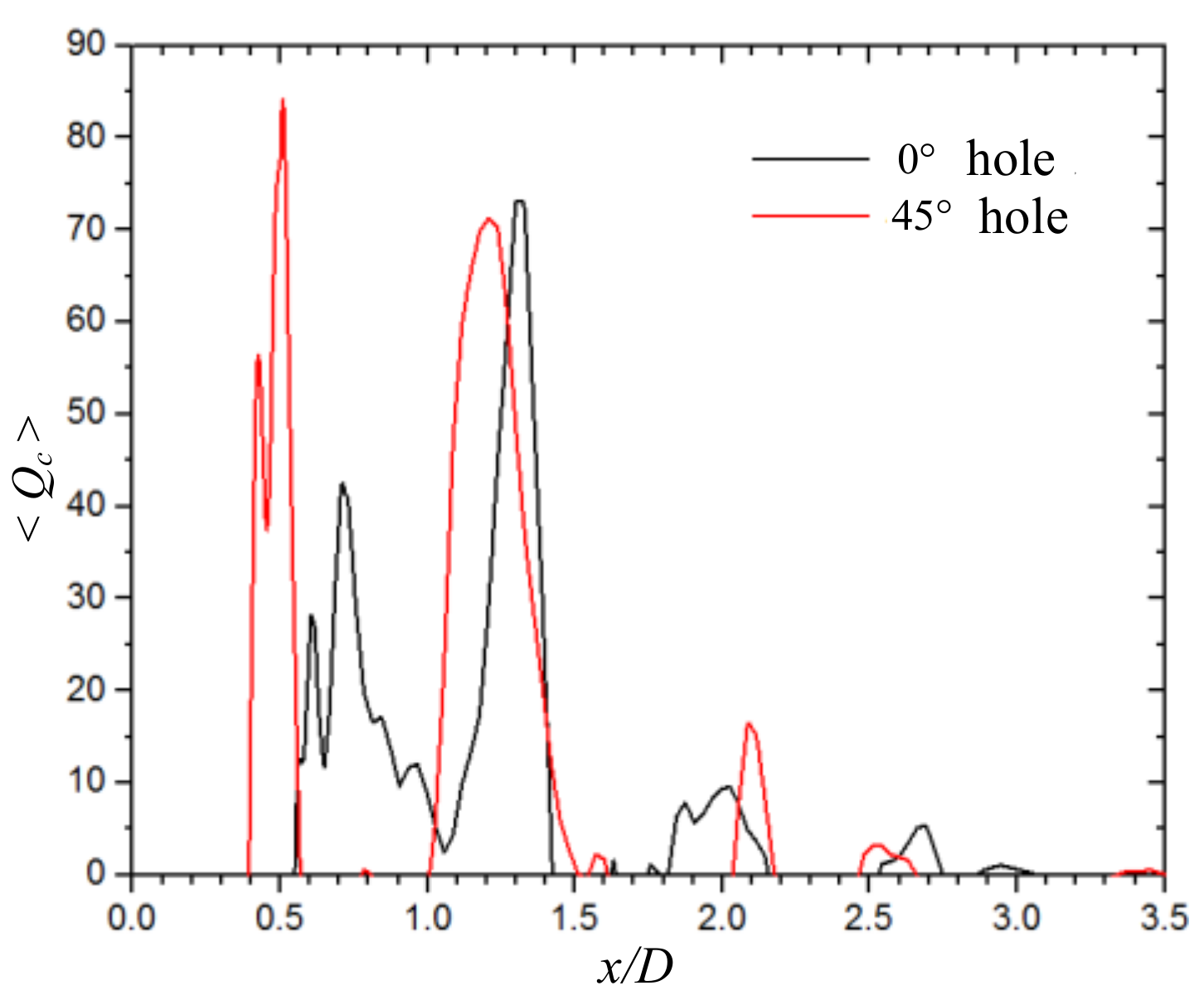
Figure 10 shows the mean second invariant in the jet space at y/D = 0.05 along the x direction. For the MCIJ, the connected vortices are prevalent in the range of x/D = 0.5~1.5; two large vortex rings appear at the locations of x/D = 0.7 and x/D = 1.3. For the SIJ, only two large vortex rings appear at the locations of x/D = 0.5 and x/D = 1.3 due to the significant entrainment and aggregation effects for the swirling jet. Compared to the MCIJ, the first large vortex ring from the jet free shear layer has a bigger intensity, while the second large vortex covers a much wider area; hence, the unconnected vortex region occurs. There are several recirculation vortices with weak intensity in the range of the flow acceleration zone due to the entrained recirculation flow; the generated locations and number of these vortices are also different for the MCIJ and SIJ due to the swirl effect.

4.2. Spectral Characteristics of Jet Space and Near Wall

The spectrum analysis of the jet space and near wall is expected to obtain an intrinsic evolution mechanism of the coherent structure. The dimensionless parameter of the frequency (f) is the Strouhal number (St), which can be represented as
S t = f × D / U b
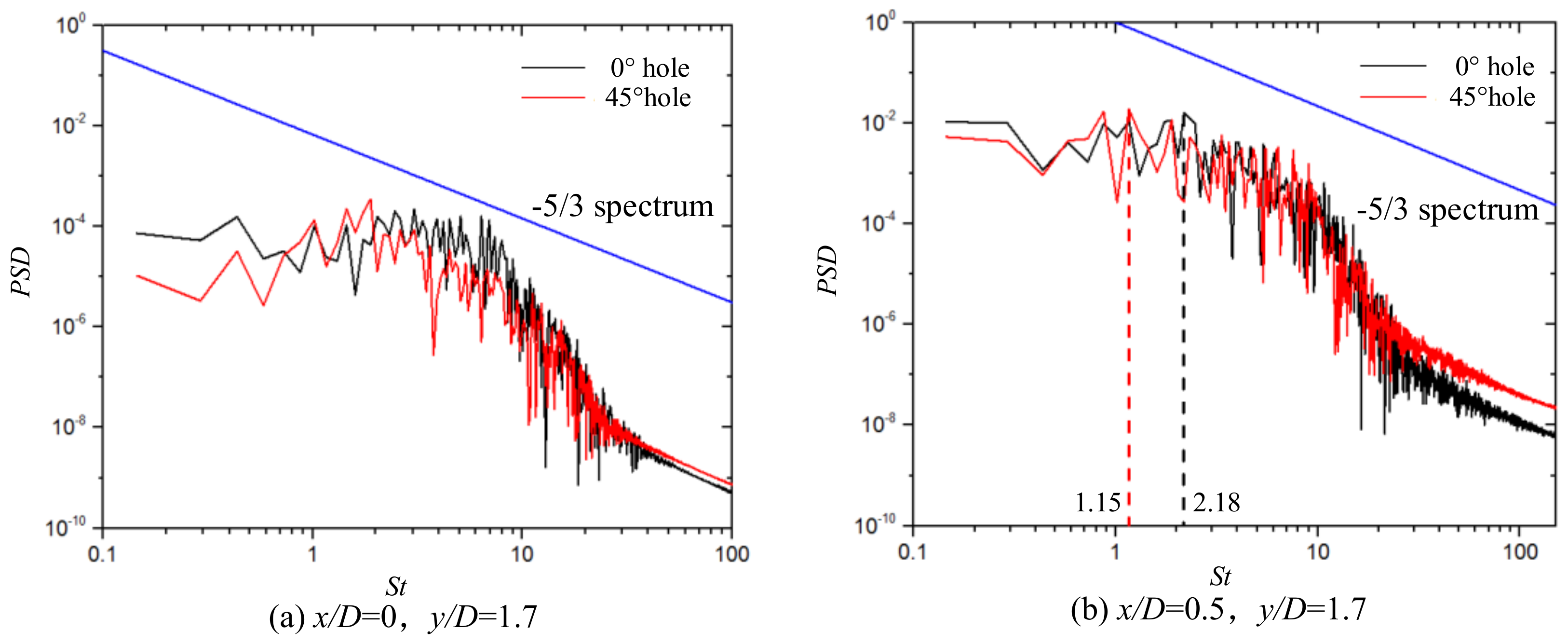
Figure 11 shows the power spectral density of the axial fluctuating velocity in jet space at x/D = 0, y/D = 1.7 and x/D = 0.5, y/D = 1.7. Two positions are located in the potential flow core region and axial shear layer, respectively. It can be seen that frequency attenuation in these regions contains a −5/3 energy spectrum region for the jets issuing from the 0° straight hole and 45° spiral hole. Due to the action of the vortices in the shear layer of the jet, the magnitude of the power spectral density in the shear layer is higher than that in the potential flow core region. It is indicated that there is an inertia sub-region in the simulation of turbulent flow field, but the interval length of the region is relatively short. Following the inertia sub-region, the power spectral density decays rapidly, which may be related to the truncation effect of the filter in the turbulent model. A common characteristic for non-swirling jets is the distinct formation of periodic structures in the axial shear layer. The natural frequency corresponds to the axi-symmetric vortex rolling up in the vicinity of the nozzle outlet, and primary vortices are alternatingly shed with the sub-harmonic frequency in the vortex pairing process. The swirling flow issuing from the 45° spiral hole is weak with a swirling number of about 0.18, and the power spectra for the u-velocity component for the non-swirling and swirling issue from the differences of two holes exit in the sub-harmonic frequency. For the non-swirling and swirling impinging jets, both of the natural frequencies are about 1, and the sub-harmonic frequencies are 2.18 and 1.15, respectively. It can be noted that as swirl is applied, the sub-harmonic and fundamental frequencies become less distinct, which may be due to the interaction of the azimuthal mode instability with the base flow instabilities at the common actions of azimuthal and axial shears.
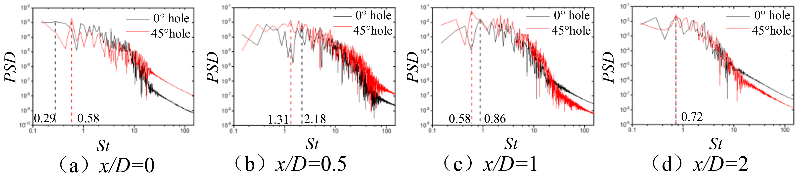
Figure 12 shows the power spectral density of radial fluctuating velocity at different locations of y/D = 0.05 near the target surface. Overall, both of the change trends are consistent for the non-swirling and swirling jets. As swirl is applied, power spectral densities become slightly higher at the downstream region. In Figure 12a, the radial velocity fluctuating at the stagnation point is quite weak, the power spectrum is lower in two orders of magnitude compared to the downstream region of other positions, and the sub-harmonic frequency is not distinct. In Figure 12b, for the jet of the 45° spiral hole, the wall jet occurs earlier along the wall and the radial fluctuating velocity is larger at x/D = 0.5; that is, the power spectrum peak of the radial fluctuating velocity has a smaller frequency. For the jet of the 0 ° straight hole, airflow near the wall at x/D = 0.5 begins to deflect gradually and enters the wall-free region. The scale of the airflow vortex is smaller and unstable, which results in two distinct frequencies of the power spectrum. In Figure 12c, airflow near the wall enters the region of the wall free jet for the jets of the 0° straight hole and the 45° spiral hole; these are two distinct frequencies of the power spectrum. In Figure 12d, only the natural frequency of the power spectrum exists. After the development of the wall free jet, the radial velocity near the wall dominates the wall boundary layer and gradually stablises.

4.3. Average Flow Characteristics

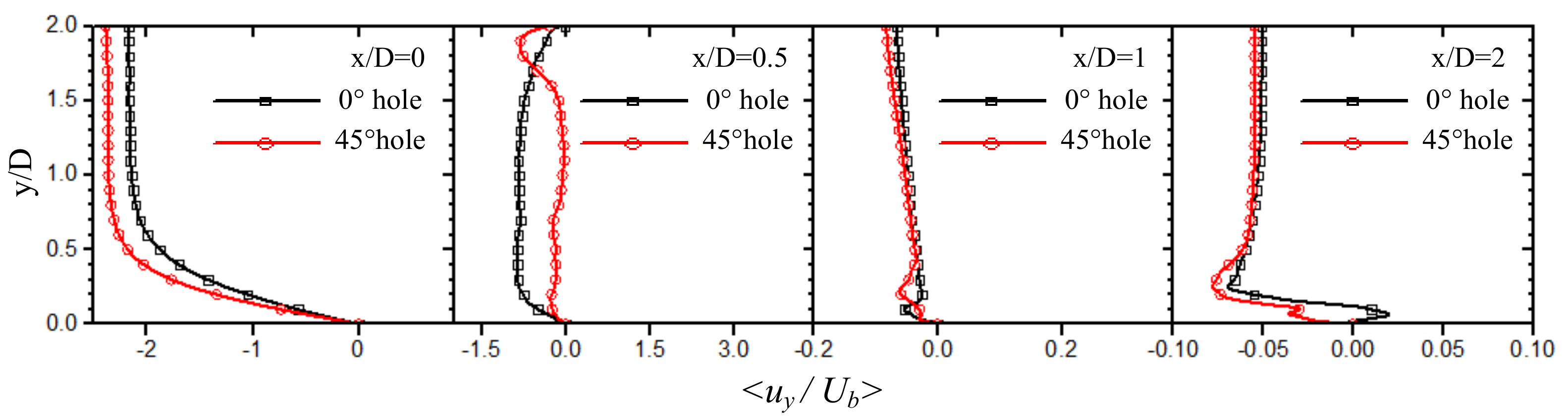
In order to obtain the steady-state distribution characteristics of the jet space velocity, Figure 13 shows the time-averaged distribution of axial velocity. When x/D = 0, the direction of the axial velocity of the jet coincides with the direction of the negative y-axis. Compared with the 0° straight hole, the obstruction of the rotation spiral groove of the 45° spiral hole makes the absolute value of time-averaged axial velocity in the center hole large. However, the length of the jet core with them is relatively close. In the region of the jet space at x/D = 0.5, the exit airflow of the jet in the spiral groove contains a tangential velocity component, and the axial velocity of the jet rotates and spreads to the periphery, leading to a relatively small absolute value of the axial time-averaged velocity of the 45° spiral hole. In the case of x/D = 1 and x/D = 2, the axial time-averaged velocities of the 0° straight hole and 45° spiral hole in most areas of the jet space are close, but in the jet region of the wall, it can be seen that after the airflow of the 45° spiral hole hits the wall, the axial time-averaged velocity of the rebounding escape airflow is large, which is more conducive to the low-speed recirculation of the stagnation zone.
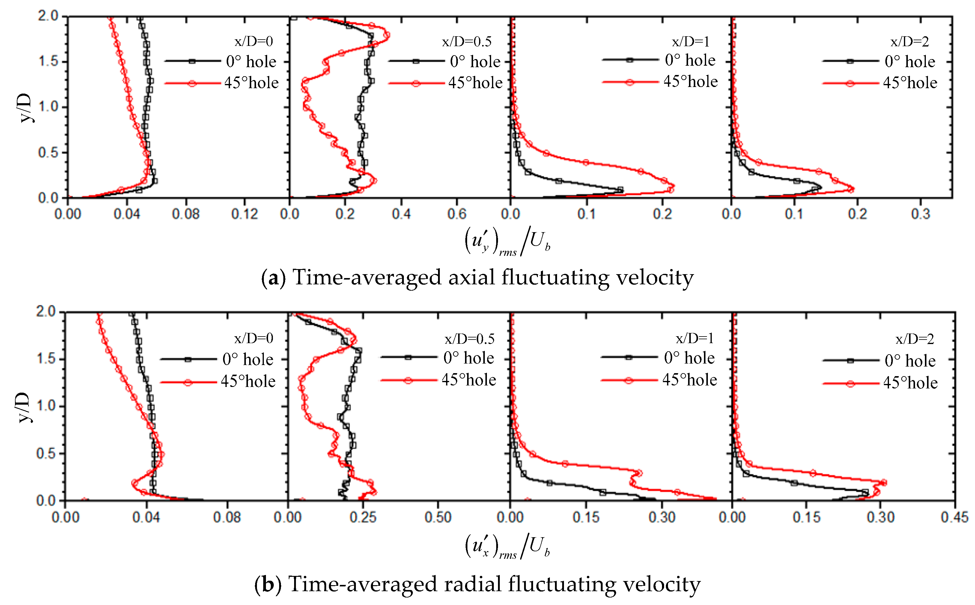
Figure 14 shows the distribution of the root mean square of the fluctuating velocity in the axial and radial directions. There is less disturbance in the core area of the jet hole with a 0° straight hole, and the fluctuating velocity in the jet space basically maintains constant. The fluctuating velocity exhibits a complex change trend of increase–decrease–increase–decrease in the periphery region of the potential flow of x/D = 0.5, due to the addition of the swirling tangential velocity with a 45° spiral hole. In the region where the potential flow is far from x/D ≥ 1, the fluctuating velocity caused by the jet entraining the surrounding low-speed airflow is almost zero. In the area near the wall, due to the deflection of the velocity, it can be seen that the fluctuating velocity of the 45° spiral hole is larger than that of the 0° straight hole, and the turbulence on the wall with the 45° spiral hole is higher than that on the jet region on the wall. The flow transport capacity of the 45° spiral hole in the jet region of the wall is higher than that of the 0° straight hole, and the heat exchange capacity also becomes stronger.

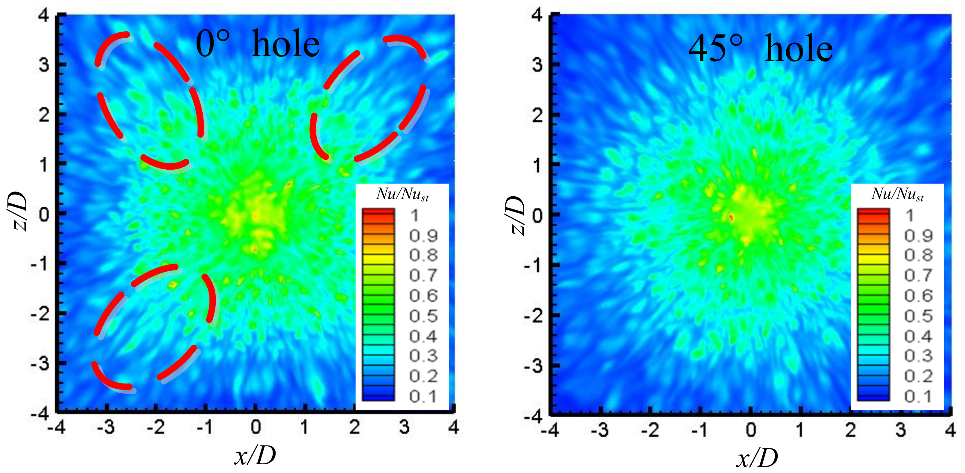
4.4. Heat Transfer Characteristics of Target Surface

Figure 15 shows the distribution of the Nu number ratio (Nu/Nust) on the target surface of the two flow guiding elements. Here, Nu is local Nusselt number, and Nust is local Nusselt number at the stagnation point. The distribution of Nu ratio on the target surface with 0° and 45° flow guiding elements shows a random distribution due to the randomness of the jet impact, and the effective area of heat transfer is roughly equivalent. Heat transfer enhances at the four corners of the jet (dashed box in the figure) with the 0° straight hole. The 0° straight hole makes the velocity at the boundary of the channel smaller than that at the boundary of the central circular hole, and the velocity in the radial direction of the groove decays faster, resulting in a difference in heat transfer at the four corners of the target surface (red dotted frame dashed box in the figure).
In Figure 15, the swirling action of the spiral groove of the 45° spiral hole increases the dispersion of the jet medium at the boundary of the spiral groove and eliminates the difference of heat transfer caused by the speed decay of the boundary between the spiral groove and the central circular hole.
To further study the difference in heat transfer characteristics between two holes, Figure 16 shows the distribution of Nu/Nust in the x direction. It can be seen that Nu maintains a high value with two flow guiding elements in the range of x/D = 0–0.5, and decays rapidly in the range of x/D = 0.5–0.75. In the range of x/D = 0.75–1.75, the decrease rate of Nu slows down and fluctuates within a certain range. At x/D = 1.75, the instantaneous Nu decreases again greatly, and then the value decreases linearly along the direction of increasing the radius in the range of x/D = 1.75–3.5. The changing trend of the instantaneous Nu is in accordance with the variation law of the Nu of the target surface with the general impinging jet. It should be pointed out that the fluctuation of instantaneous Nu in different ranges is not the same. It can be seen that the fluctuation peaks appear in the A and B regions with the 45° spiral hole in the range of x/D = 0–0.5, and the peak appears in the B region with the 0° straight hole near x/D = 0.5. In the range of x/D = 0.75–1.75, there are two peaks with large spacing in the C region with the 45° spiral hole, while the instantaneous Nu of the 0° straight hole has four peaks with different fluctuation amplitudes in the C region. In the range of x/D = 1.75–2.6 of the D region, there are two peaks of approximately “sinusoidal” change with the 0° straight hole. Although there are two peaks with the 45° spiral hole, the corresponding Nu peak is greater than that of the 0° straight hole. In general, the Nu number of the jet impacting target surface with the 45° spiral hole is about 5–10% higher than that of the 0° straight hole, and the fluctuation is more severe in each sub-area.
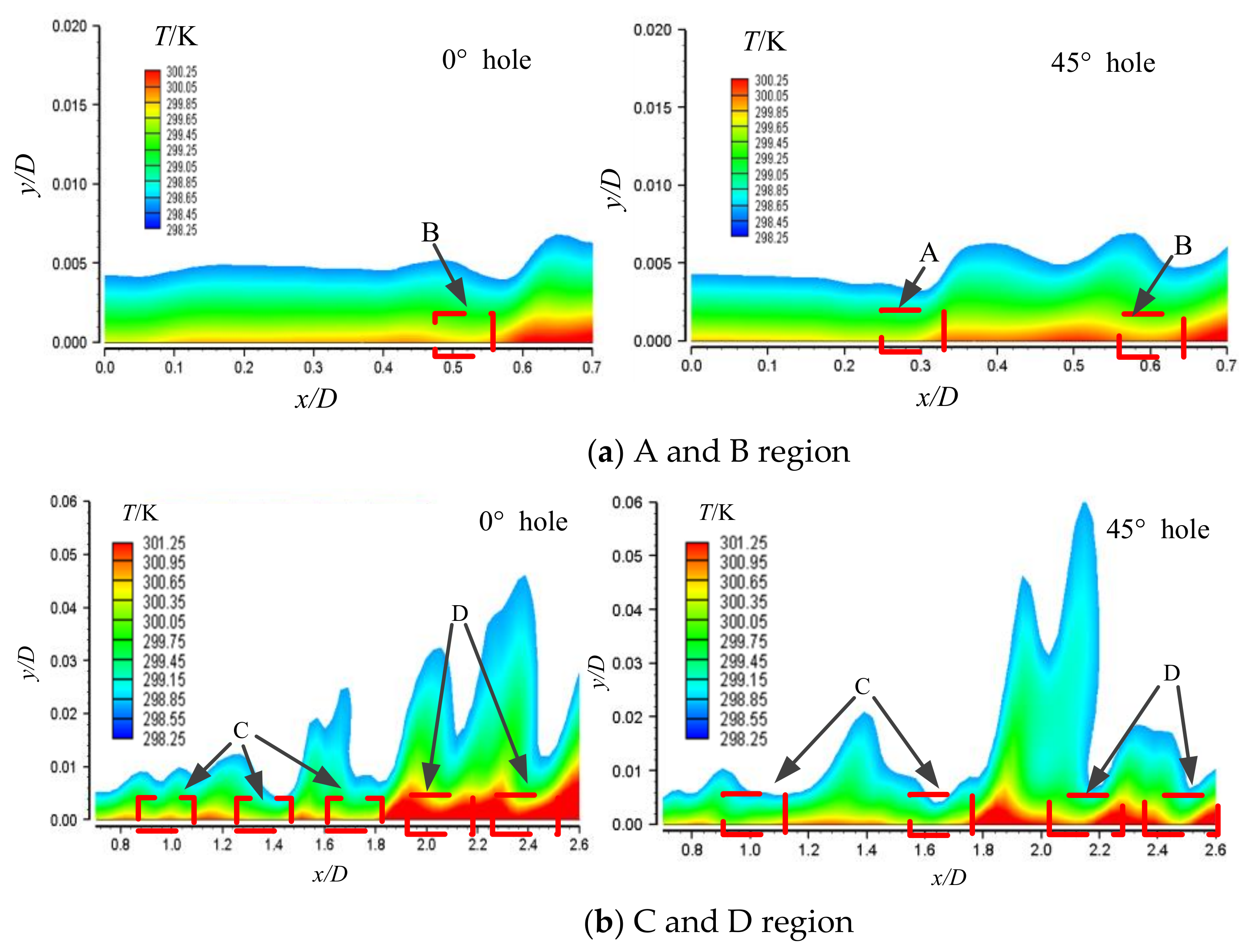
Figure 17 shows the temperature distribution of near wall in the jet core and wall jet region. In Figure 17a, the temperature boundary layer of the 0° straight hole is suddenly thickened at x/D = 0.1, so that the effective erosion of the jet core region is weakened, resulting in a sharp decrease in Nu in the corresponding position. In the range of x/D = 0.1–0.5, as the jet core region impacts the target surface and deflects into the adherent flow, the temperature boundary layer is slowly thickened, so that the Nu of the target surface decreases. In the range of x/D = 0.5–0.6 in the B region, the vortex of the free shear boundary layer in the jet space disturbs the adherent flow, resulting in the suddenly thinning of the temperature boundary layer in this interval, causing a Nu peak, and then the jet enters the jet region of the wall. The temperature boundary thickness increases rapidly, resulting in a rapid decay of the instantaneous Nu along the direction of increasing x. In Figure 17a, the flow of the 45° spiral hole is similar to that of the 0° straight hole in the range of x/D = 0–0.2. Near x/D = 0.2, the wave peak of Nu appears in the A region because of the influence of the shear boundary layer with a center hole area of 45° spiral hole. Then, under the action of the tangential airflow of the spiral groove, the jet begins to fluctuate gradually near the temperature boundary layer at x/D = 0.3. At x/D = 0.6, tilt and scour of the tangential flow of the spiral groove (B region of 45° spiral hole) causes the boundary layer to become thinner, corresponding to the instantaneous Nu peak in the position. In Figure 17b, the turbulent flow gradually forms after the 0° straight hole enters the jet region of the wall, causing small pitch fluctuation in the temperature boundary layer in the range of x/D=0.7–1.2, corresponding to the first and the second Nu peaks in the C interval. The fluctuation of the temperature boundary layer increases in the range of x/D = 1.4–1.8, resulting in two Nu peaks at x/D = 1.4 and x/D = 1.8, corresponding to the two larger Nu peaks behind the C interval. In the range of x/D = 1.8–2.6, the temperature boundary layer of the near wall is sharply thickened, and the fluctuation amplitude of the boundary layer increases, resulting in two distinct Nu peaks in the D region. In Figure 17b, the boundary layer of the wall of the C and D regions with a 45° spiral hole is obviously thinner, and the place where the Nu peak appears is the thinner part of the temperature boundary layer. It can be seen that the thickness of the temperature boundary layer and its change directly determine the strength of the heat transfer of the target surface, and both are strongly correlated.

4.5. Frequency Characteristics of Temperature Fluctuation on the Target Surface

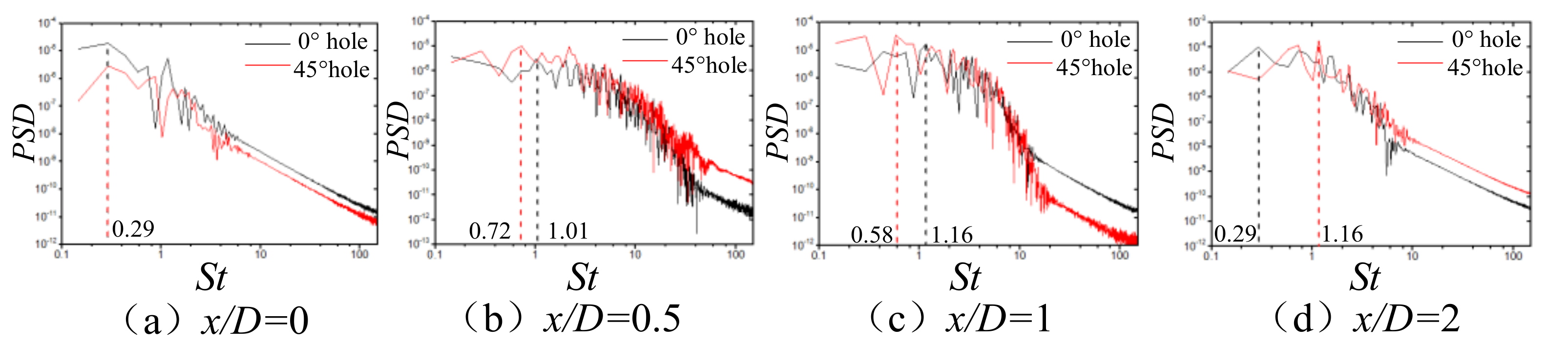
Figure 18 shows the distribution of the power density spectrum of the fluctuating temperature on the target surface of x/D = 0, x/D = 0.5, x/D = 1, and x/D = 2.
In Figure 18a, the temperature fluctuating degree of the 0° straight hole is larger than that of the 45° spiral hole, and the frequency characteristic values at the peak of the temperature fluctuation are consistent, and St is 0.29. At this position, the corresponding frequencies of the peaks of the radial fluctuating velocity are 0.29 and 0.58, and the frequency at the peak of the velocity fluctuation with the 0° straight hole is consistent with the frequency at the peak of the temperature fluctuation, but the frequency at the peak of the temperature fluctuation with the 45° spiral hole is behind the frequency at the peak of the velocity fluctuation. In Figure 18b, the spectrum energy value of temperature fluctuation with the 45° spiral hole is higher, and the frequency corresponding to the fluctuating peak of both changes, and the St are 1.01 and 0.72. Since the airflow on the wall 45° spiral hole enters the position of turbulent flow earlier, the distance between adjacent temperature peaks is larger at x/D = 0.5. The peak frequencies of the radial fluctuating velocity are 2.18 and 1.31, indicating that the scale of temperature fluctuation does not correspond to the spatial scale of velocity fluctuation, and its scale is larger than the scale of velocity fluctuation. In Figure 18c, the frequencies at the peaks of the temperature fluctuation are 1.16 and 0.58, and there is little change for the frequency at the peak of the temperature fluctuation with the 0° straight hole and 45° spiral hole compared with the position of x/D = 0.5. There is little displacement for the frequencies at the peaks of fluctuations of the spiral hole to some sides. However, the frequencies at the peaks of the radial fluctuating velocity of both are 0.86 and 0.58 and greatly reduce, which is related to the growth of the vortex of the boundary layer of the wall, and the larger vortex of the boundary layer of the wall causes the frequency of velocity fluctuation to decrease. In Figure 18d, the frequencies at the peak of temperature fluctuation of the 0° straight hole and the 45° spiral hole are 1.16 and 0.29, respectively. This is because the distance of two fluctuation peaks of the temperature boundary layer of the 45° spiral hole in the position suddenly becomes smaller, resulting in an increase in frequency when passing the position of x/D = 2. Due to the continued growth of the vortex in the velocity boundary layer of the wall, the peak frequency of the fluctuation of the radial fluctuating velocity of both also reduces.

5. Conclusions

In this work, The LES numerical calculation method is employed for the swirl nozzle with a spiral hole. WALEM is selected to study the relationship between structure and heat transfer characteristics of the 0° straight hole and 45° spiral hole under the conditions of Re = 16,000 and H/D = 2 for jet impingement cooling. The flow characteristics of the vortex structure and evolution of the nozzle in the jet space with two kinds of flow guiding elements are analyzed.
From the dynamics of the coherent structure of the jet, the differences of the coherent structure with two kinds of flow guiding elements are compared. The coherent structure is analyzed, which affects the spectrum characteristics of the turbulence in the jet space. On the other hand, the transient heat transfer characteristics of the impact target surface are studied. The transient heat transfer characteristics of the target surface and the causes are analyzed. The mutual coupling relationship between the airflow and heat transfer on the adherent surface is shown. The main conclusions are as follows:
(1)
Compared with experimental data, the LES numerical simulation method can accurately simulate the flow and heat transfer change of the rotating impinging jet of the flow guiding element. With the same grid scale and time step, the WALEM can better capture and predict the flow results near the wall than the DSM subgrid model.
(2)
For the jet with a 0° straight hole, it forms a “round table” region with a relatively small diffusion area around the center of the jet. The jet from the 45° spiral groove has a large tangential velocity component, and the blended airflow forms a “skirt-type” region with a larger diffusion area on the periphery of the central potential flow region.
(3)
In the area near the wall, due to the velocity deflection, the fluctuating velocity of the 45° spiral hole is larger than that of the 0° straight hole; that is, the turbulence degree of the jet of the wall with the 45° spiral hole is higher, and the ability of airflow transportation is higher. Compared with the MCIJ of the 0° straight angle, the heat transfer intensity of the target surface for the SIJ with a 45° spiral hole slightly increases, and the enhanced amplitude is within 5–10%. Excited swirl can enhance heat transfer on the concave surface at a small impact distance of H/D = 2.
(4)
The vortex distribution of the boundary layer of the jet region of the wall affects the fluctuation of the temperature boundary layer, and the fluctuation law of the temperature boundary layer is consistent with the change of the Nu number. The scale of temperature fluctuation on the wall is larger than the scale of radial velocity fluctuation near the wall, and there is no correspondence between them both.

Author Contributions

Conceptualization, L.X. (Liang Xu). and J.G.; methodology, L.X. (Lei Xi); validation, L.X. (Liang Xu), J.G. and L.X. (Lei Xi); formal analysis, Y.M.; investigation, X.Z.; resources, J.G.; data curation, X.Z.; writing—original draft preparation, Y.M.; writing—review and editing, X.Z.; visualization, Y.M.; supervision, Y.L. and L.X. (Lei Xi); project administration, Y.L. and L.X. (Liang Xu). All authors have read and agreed to the published version of the manuscript.

Funding

The research work is supported by Guangdong Basic and Applied Basic Research Foundation (2018A030313183), National Natural Science Foundation of China (51876157) and National Natural Science Foundation of Shannxi Province in China (2019JM-096).

Conflicts of Interest

No conflict of interest exists in the submission of this manuscript, and the manuscript is approved by all authors for publication. I would like to declare on behalf of my co-authors that the work described was original research that has not been published previously, and is not under consideration for publication elsewhere, in whole or in part. All the authors listed have approved the manuscript that is enclosed.

Nomenclature

C s Smagorinsky constant
c p specific heat
D1vane pack hub diameter
Dnozzle diameter
D/dsurface diameter-to-jet diameter
kVon Karman constant
<k>Turbulent kinetic energy
lDistance closest to the wall
LsMixing length for subgrid scales
LESIQνindex of quality criterion for LES
Glow pass filter
Hjet spacing
H/Djet spacing-to-jet diameter
ffrequency
NuNusselt number
PrPrandtl number
P r t sub-grid Prandtl number
PPressure
PSDPower spectral density
q j S G S turbulent sub-grid scale heat flux
Qthe second invariant of velocity gradient
r/Dlocal radial coordination-to-diameter
ReReynolds number
SijStrain rate tensor
S ¯ i j strain rate tensor for resolved scale
SSwirl number
StStrouhal number
Ttemperature
ttime
u i ¯ Filtered xi-velocity component
u x the radial fluctuating velocity
u y the axial fluctuating velocity
uyaxial velocity
UbInlet mean velocity
Urradial velocity
VVolume of the computational cell
x/Dflow distance-to-diameter
y/Daxial distance-to-diameter
Greek Symbols
μFluid dynamic viscosity
μ t sub-grid dynamic viscosity
νFluid kinematic viscosity
ν t sub-grid kinematic viscosity
λthermal conductivity
ρdensity
θhelix angle
δ i j   Kronecker delta
Γ thermal diffusivity of air
Γ t subgrid scale thermal diffusivity
Δ characteristic filter width
τ i j S G S subgrid stresses
φ ¯ resolved component
φ ˜ subgrid component
Subscript
i,jindex of coordinate direction
rmsroot mean square value of a variable
stthe stagnation point

References

  1. Harmon, W.V.; Wright, L.M.; Crites, D.C.; Morris, M.C.; Riahi, A. Combined Effects of Jet Plate Thickness and Fillet Radius on Leading Edge Jet Impingement with Round and Racetrack Shaped Jets. In Proceedings of the ASME Turbo Expo 2015: Turbine Technical Conference and Exposition, Montreal, QC, Canada, 15–19 June 2015; pp. 15–19. [Google Scholar]
  2. Liu, L.; Zhu, X.; Liu, H.; Du, Z. Effect of tangential jet impingement on blade leading edge impingement heat transfer. Appl. Therm. Eng. 2018, 130, 1380–1390. [Google Scholar] [CrossRef]
  3. Zhou, J.; Wang, X.; Li, J. Influences of effusion hole diameter on impingement/effusion cooling performance at turbine blade leading edge. Int. J. Heat Mass Transf. 2019, 134, 1101–1118. [Google Scholar] [CrossRef]
  4. Qiu, D.; Wang, C.; Luo, L.; Wang, S.; Zhao, Z.; Wang, Z. On heat transfer and flow characteristics of jets impinging onto a concave surface with varying jet arrangements. J. Therm. Anal. Calorim. 2020, 141, 57–68. [Google Scholar] [CrossRef]
  5. Singh, A.; Prasad, B. Influence of novel equilaterally staggered jet impingement over a concave surface at fixed pumping power. Appl. Therm. Eng. 2019, 148, 609–619. [Google Scholar] [CrossRef]
  6. Liu, Z.; Li, J.; Feng, Z. Numerical Study of Swirl Cooling in a Turbine Blade Leading-Edge Model. J. Thermophys. Heat Transf. 2015, 29, 166–178. [Google Scholar] [CrossRef]
  7. Lin, G.; Kusterer, K.; Bohn, D.; Sugimoto, T.; Tanaka, R.; Kazari, M. Impingement Cooling with Spent Flow in the Blade Leading Edge Using Double Swirl Chambers. In Proceedings of the 15th International Heat Transfer Conference, Kyoto, Japan, 10–15 August 2014; Volume 15, pp. 4291–4305. [Google Scholar]
  8. Zhou, J.; Wang, X.; Li, J.; Hou, W. Effects of Target Channel Shapes on Double Swirl Cooling Performance at Gas Turbine Blade Leading Edge. J. Eng. Gas Turbines Power 2019, 141, 071004. [Google Scholar] [CrossRef]
  9. Fénot, M.; Dorignac, E.; Lalizel, G. Heat transfer and flow structure of a multichannel impinging jet. Int. J. Therm. Sci. 2015, 90, 323–338. [Google Scholar] [CrossRef]
  10. Nanan, K.; Wongcharee, K.; Nuntadusit, C.; Eiamsa-Ard, S. Forced convective heat transfer by swirling impinging jets issuing from nozzles equipped with twisted tapes. Int. Commun. Heat Mass Transf. 2012, 39, 844–852. [Google Scholar] [CrossRef]
  11. Eiamsa-Ard, S.; Nanan, K.; Wongcharee, K. Heat transfer visualization of co/counter-dual swirling impinging jets by thermochromic liquid crystal method. Int. J. Heat Mass Transf. 2015, 86, 600–621. [Google Scholar] [CrossRef]
  12. Nuntadusit, C.; Wae-Hayee, M.; Bunyajitradulya, A.; Eiamsa-Ard, S. Visualization of flow and heat transfer characteristics for swirling impinging jet. Int. Commun. Heat Mass Transf. 2012, 39, 640–648. [Google Scholar] [CrossRef]
  13. Xu, L.; Lan, J.; Ma, Y.; Gao, J.; Li, Y. Numerical study on heat transfer by swirling impinging jets issuing from a screw-thread nozzle. Int. J. Heat Mass Transf. 2017, 115, 232–237. [Google Scholar] [CrossRef]
  14. Xu, L.; Xiong, Y.; Xi, L.; Gao, J.; Li, Y.; Zhao, Z. Numerical Simulation of Swirling Impinging Jet Issuing from a Threaded Hole under Inclined Condition. Entropy 2019, 22, 15. [Google Scholar] [CrossRef] [Green Version]
  15. Uddin, N.; Weigand, B.; Younis, B.A. Comparative study on heat transfer enhancement by turbulent impinging jet under conditions of swirl, active excitations and passive excitations. Int. Commun. Heat Mass Transf. 2019, 100, 35–41. [Google Scholar] [CrossRef] [Green Version]
  16. Erlebacher, G.; Hussaini, M.Y.; Speziale, C.G.; Zang, T.A. Toward the large-eddy simulation of compressible turbulent flows. J. Fluid Mech. 1992, 238, 155–185. [Google Scholar] [CrossRef] [Green Version]
  17. Le Ribault, C.; Sarkar, S.; Stanley, S.A. Large eddy simulation of a plane jet. Phys. Fluids 1999, 11, 3069–3083. [Google Scholar] [CrossRef] [Green Version]
  18. Dai, Y.; Kobayashi, T.; Taniguchi, N. Large Eddy Simulation of Plane Turbulent Jet Flow Using a New Outflow Velocity Boundary Condition. JSME Int. J. Ser. B 1994, 37, 242–253. [Google Scholar] [CrossRef] [Green Version]
  19. Beaubert, F.; Viazzo, S. Large eddy simulations of plane turbulent impinging jets at moderate Reynolds numbers. Int. J. Heat Fluid Flow 2003, 24, 512–519. [Google Scholar] [CrossRef]
  20. Germano, M.; Piomelli, U.; Moin, P.; Cabot, W.H. A dynamic subgrid-scale eddy viscosity model. Phys. Fluids A Fluid Dyn. 1991, 3, 1760–1765. [Google Scholar] [CrossRef] [Green Version]
  21. Lilly, D.K. A proposed modification of the Germano subgrid-scale closure method. Phys. Fluids A Fluid Dyn. 1992, 4, 633–635. [Google Scholar] [CrossRef]
  22. Nicoud, F.; Ducros, F. Subgrid-Scale Stress Modelling Based on the Square of the Velocity Gradient Tensor. Flow Turbul. Combust. 1999, 62, 183–200. [Google Scholar] [CrossRef]
  23. Dewan, A.; Dutta, R.; Srinivasan, B. Recent Trends in Computation of Turbulent Jet Impingement Heat Transfer. Heat Transf. Eng. 2012, 33, 447–460. [Google Scholar] [CrossRef]
  24. ANSYS Inc. Fluent User Guide and Fluent Theory Guide, Version 16.0; ANSYS Inc.: Canonsburg, PA, USA, 2016. [Google Scholar]
  25. Ianiro, A.; Cardone, G. Heat transfer rate and uniformity in multichannel swirling impinging jets. Appl. Therm. Eng. 2012, 49, 89–98. [Google Scholar] [CrossRef]
  26. Xu, L.; Yang, T.; Sun, Y.; Xi, L.; Gao, J.; Li, Y.; Li, J. Flow and heat transfer characteristics of a swirling impinging jet issuing from a threaded nozzle. Case Stud. Therm. Eng. 2021, 25, 100970. [Google Scholar] [CrossRef]
  27. Celik, I.B.; Cehreli, Z.N.; Yavuz, I. Index of Resolution Quality for Large Eddy Simulations. J. Fluids Eng. 2005, 127, 949–958. [Google Scholar] [CrossRef]
  28. Jeong, J.; Hussain, F. On the identification of a vortex. J. Fluid Mech. 1995, 285, 69–94. [Google Scholar] [CrossRef]
Figure 1. Computational domains and grid of a swirling impinging jet on a flat target: (a) computational domains, (b) computational grid.
Applsci 11 07167 g001
Figure 2. (a) Mean radial velocity and (b) turbulent kinetic energy at r/D = 2.
Applsci 11 07167 g002
Figure 3. The ratio of the sub-grid viscosity to the molecular viscosity at r/D = 0 and r/D = 1; (a) r/D = 0; (b) r/D = 1.
Applsci 11 07167 g003
Figure 4. Radial distribution of Nu at the flat target wall.
Applsci 11 07167 g004
Figure 5. Geometrical structure and computational domains.
Applsci 11 07167 g005
Figure 6. The contours of the instantaneous axial velocity in the XOY and YOZ planes.
Applsci 11 07167 g006
Figure 7. The distribution of pressure in the XOY and YOZ planes.
Applsci 11 07167 g007
Figure 8. Streamlines and velocity vectors in the XOY and YOZ planes.
Applsci 11 07167 g008
Figure 9. Instantaneous iso-Q-criterion surface for the MCIJ and SIJ.
Applsci 11 07167 g009
Figure 10. The mean second invariant in jet space at y/D = 0.05 along the x direction.
Applsci 11 07167 g010
Figure 11. Power spectral density of the axial fluctuating velocity in jet space.
Applsci 11 07167 g011
Figure 12. Power spectral density of radial fluctuating velocity near the target surface.
Applsci 11 07167 g012
Figure 13. The distribution of axial time-averaged velocity at different positions.
Applsci 11 07167 g013
Figure 14. Distribution of root mean square of the axial and radial fluctuating velocities.
Applsci 11 07167 g014
Figure 15. Cloud plot of the distribution of instantaneous Nu number ratio on the target surface.
Applsci 11 07167 g015
Figure 16. The distribution of Nu/Nust in the x direction.
Applsci 11 07167 g016
Figure 17. Temperature distribution of near-wall in the jet core and wall jet regions.
Applsci 11 07167 g017
Figure 18. Spectrum of temperature fluctuations at different positions on the impact target surface.
Applsci 11 07167 g018
Publisher’s Note: MDPI stays neutral with regard to jurisdictional claims in published maps and institutional affiliations.

