
An Economical and Precise Cooling Model and Its Application in a Single-Cylinder Diesel Engine


Abstract
:1. Introduction
2. Model of the Cooling System
2.1. Heat Rejection Model of Engine
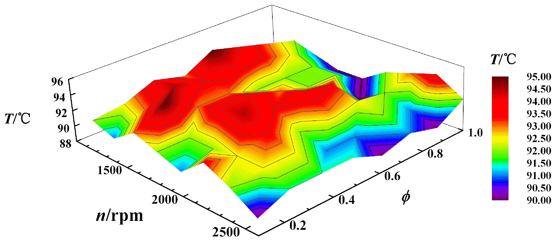
2.2. Target Temperature of the Water Jacket
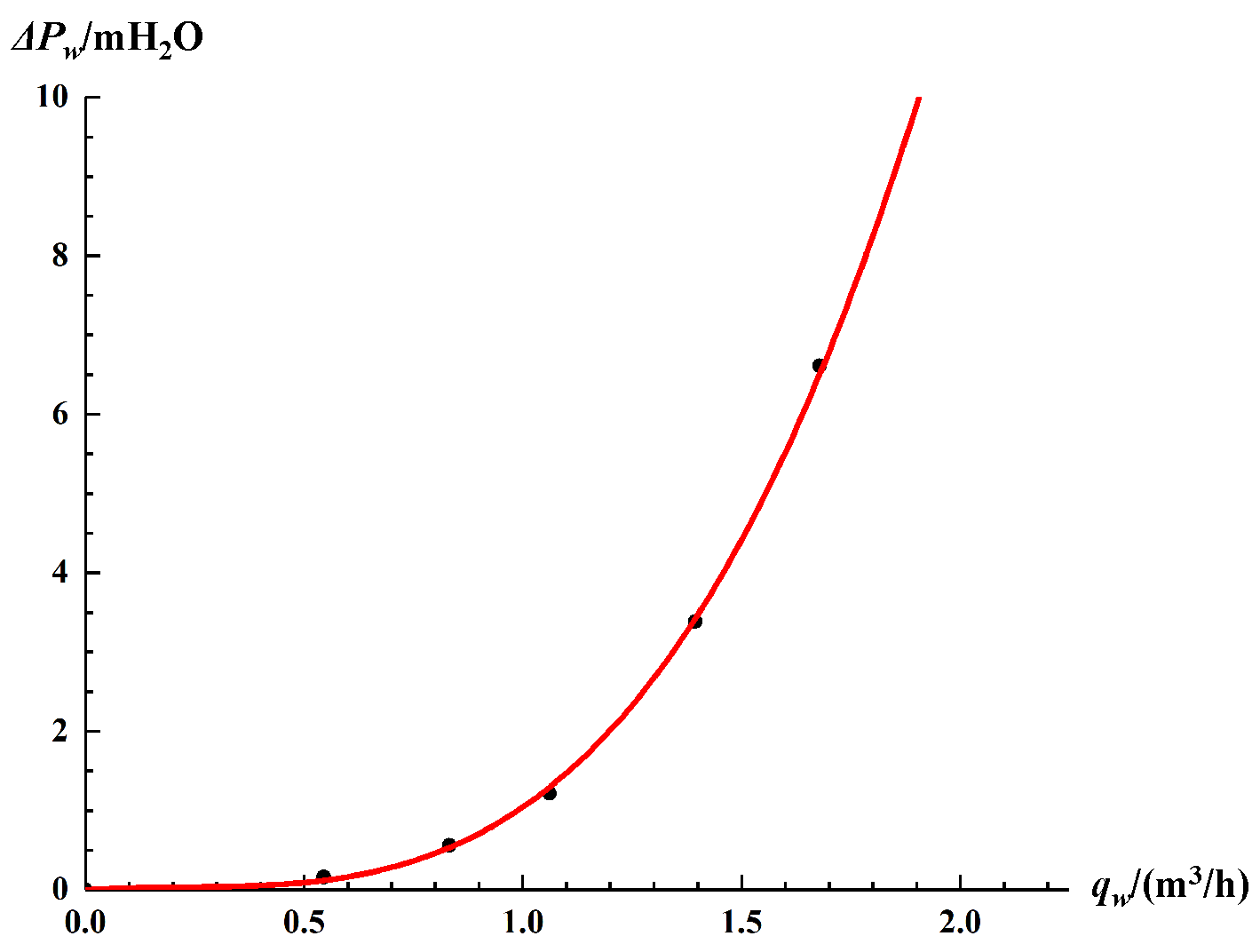
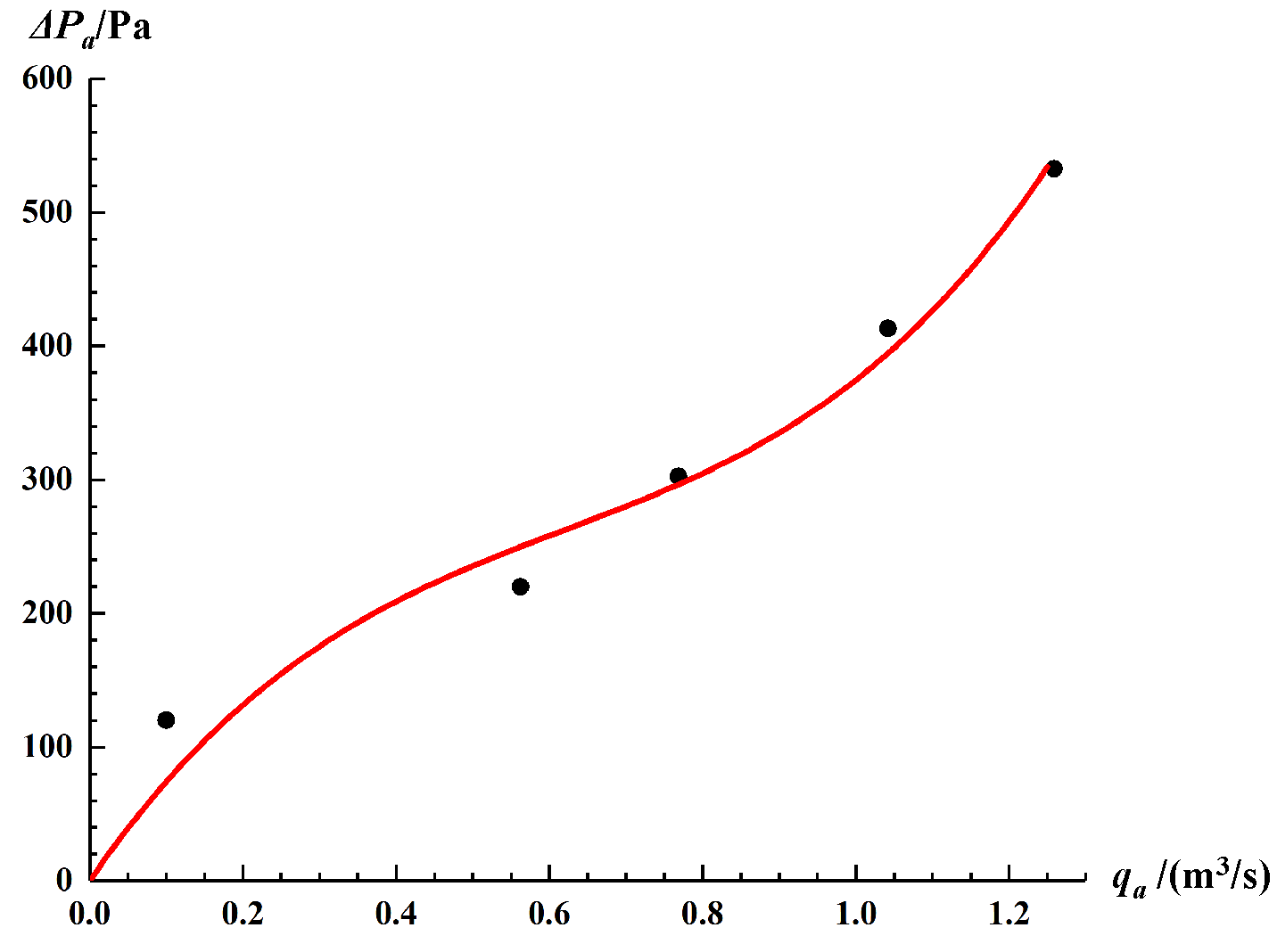
2.3. Model of the Radiator
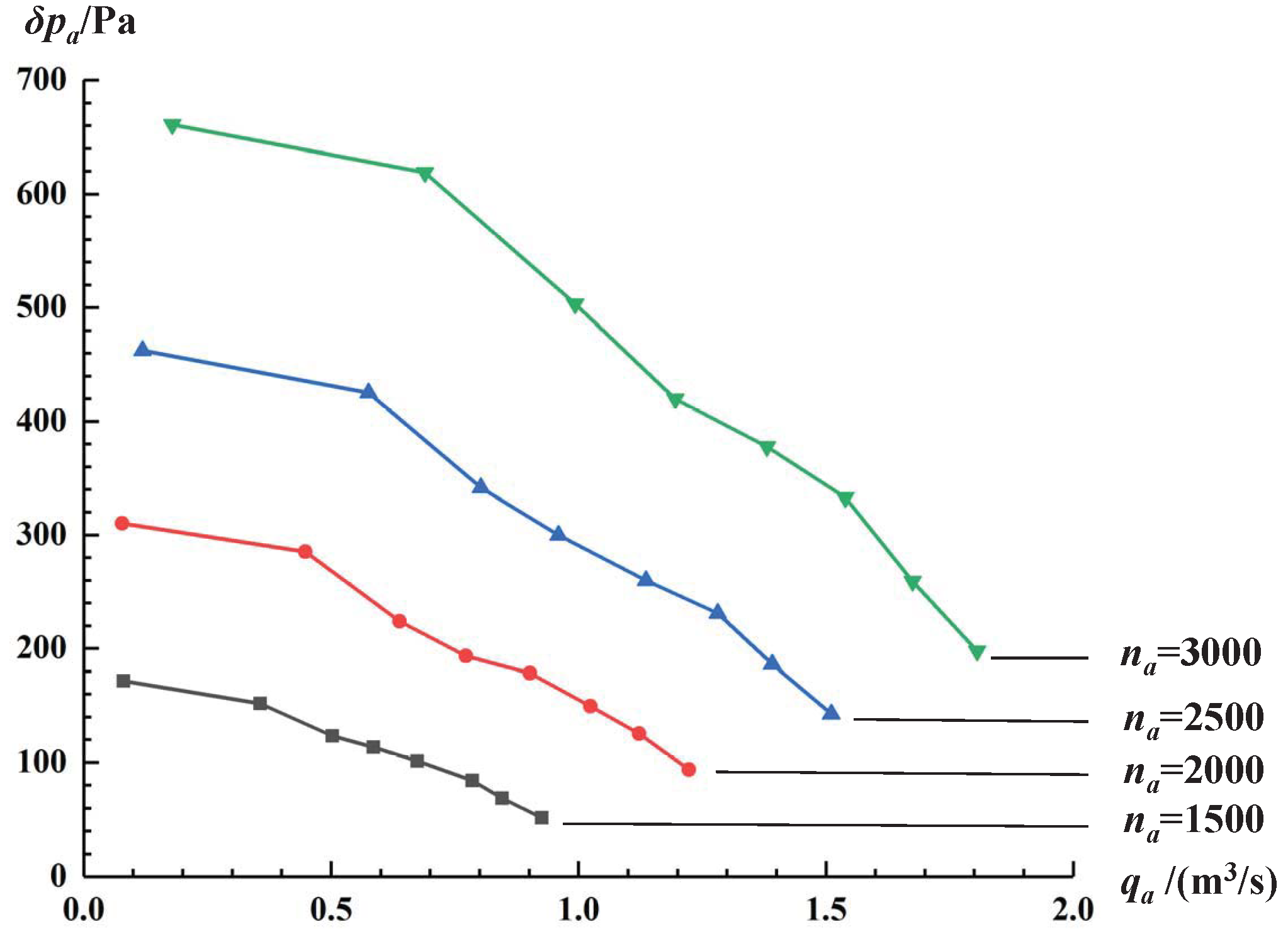
2.4. Model of the Fan and Pump
3. Model Solutions
3.1. Electric Cooling Model Solution
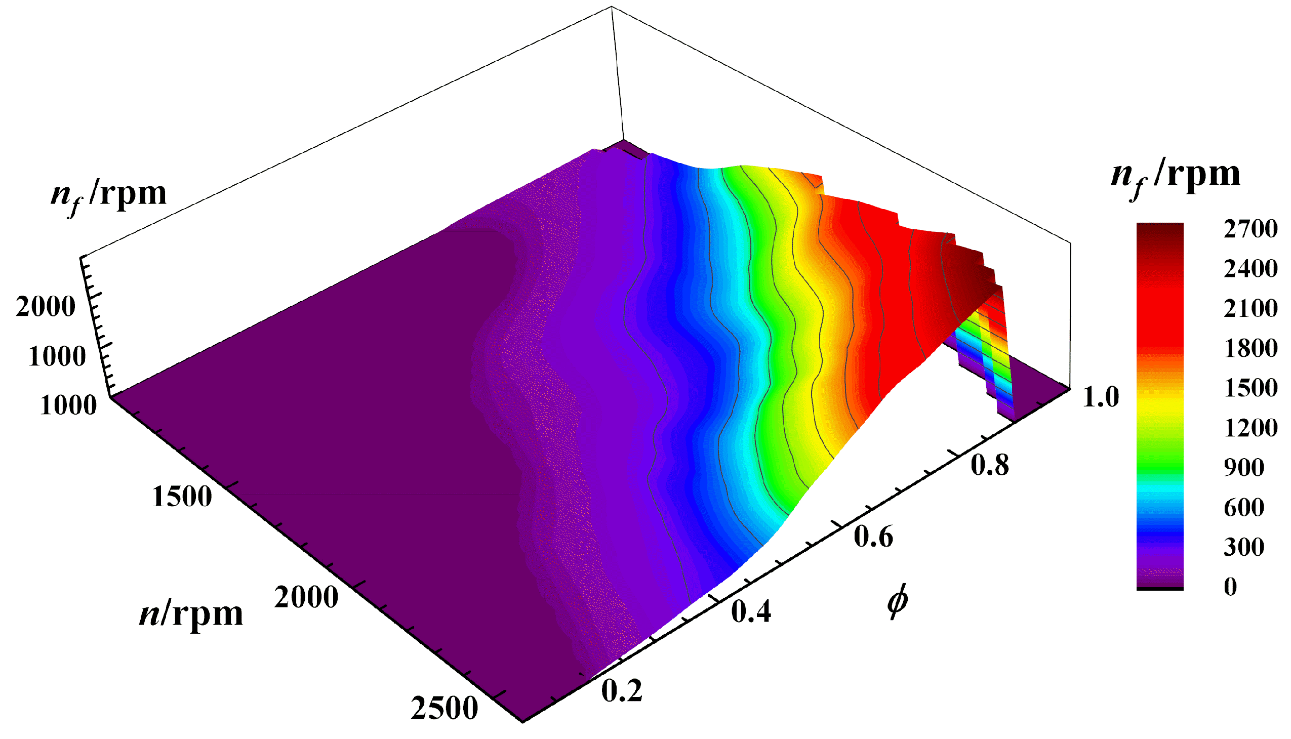
- Calculating the heat dissipation of the radiator: Plug in Equations (8) and (9) into Equation (3) to obtain,By assuming that the heat rejection in Equation (1) is equal to the heat dissipation of the radiator, one obtains:Recall that , where is the target temperature of the water jacket and is the atmospheric temperature. In Equation (11), only are unknown; thus, the fan speed can be expressed as a function of the water pump speed ,
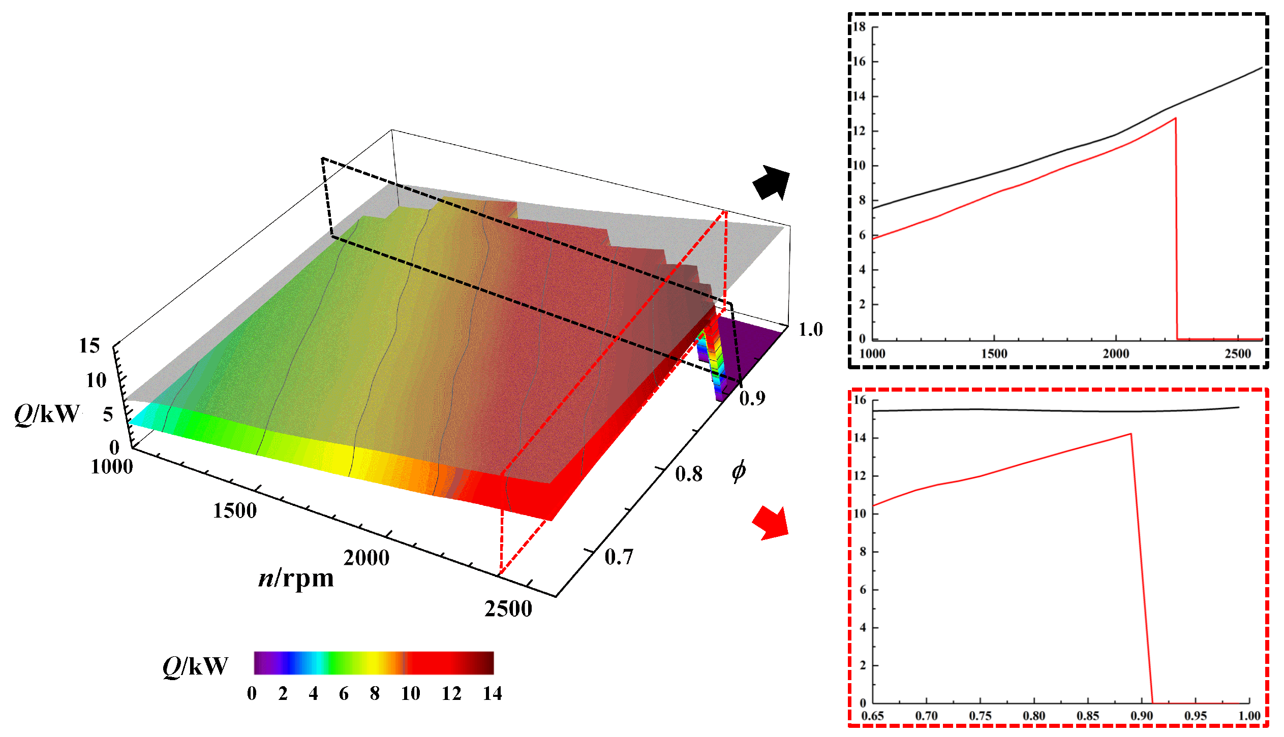
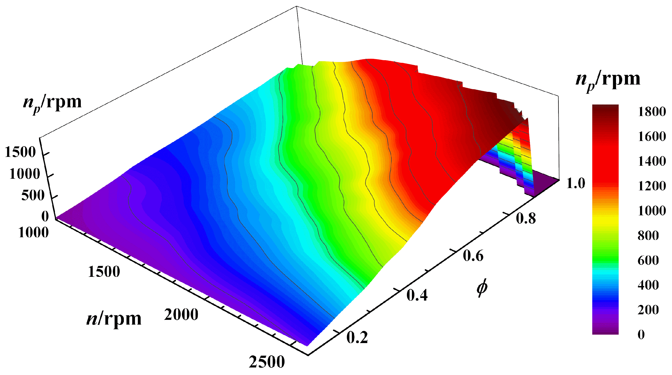
- Obtaining and the total power consumption P: P can be written as: and combined Equation (12), P can be rewritten as a single-variable function of , thus minimizing the total power consumption; therefore, P can be written as:Using this equation, and then can be solved, where P has a minimum value. At this point, the solution of the electric cooling model is complete.
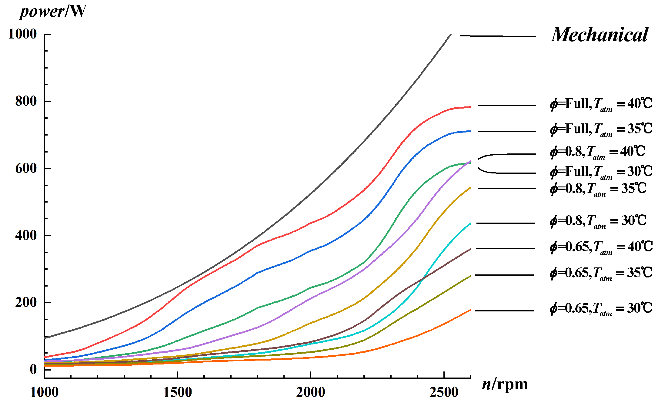
3.2. Mechanical Cooling Model Solution
4. Results and Discussion
5. Conclusions
Author Contributions
Funding
Institutional Review Board Statement
Informed Consent Statement
Data Availability Statement
Conflicts of Interest
References
- Liang, Y.; Yu, Z.; Li, W. A waste heat-driven cooling system based on combined organic Rankine and vapour compression refrigeration cycles. Appl. Sci. 2019, 9, 4242. [Google Scholar] [CrossRef] [Green Version]
- Xin, Q. Diesel Engine System Design; Elsevier: Amsterdam, The Netherlands, 2011. [Google Scholar]
- Brace, C.J.; Hawley, G.; Akehurst, S.; Piddock, M.; Pegg, I. Cooling system improvements-assessing the effects on emissions and fuel economy. Proc. Inst. Mech. Eng. Part D J. Automob. Eng. 2008, 222, 579–591. [Google Scholar] [CrossRef]
- Pang, H.; Brace, C. Review of engine cooling technologies for modern engines. Proc. Inst. Mech. Eng. Part D J. Automob. Eng. 2004, 218, 1209–1215. [Google Scholar] [CrossRef]
- Allen, D.; Lasecki, M. Thermal Management Evolution and Controlled Coolant Flow; SAE Technical Paper 2001-01-1732; SAE: Warrendale, PA, USA, 2001. [Google Scholar] [CrossRef]
- Wang, Y.; Gao, Q.; Zhang, T.; Wang, G.; Jiang, Z.; Li, Y. Advances in Integrated Vehicle Thermal Management and Numerical Simulation. Energies 2017, 10, 1636. [Google Scholar] [CrossRef]
- Katta, K.; Kim, M.; Taggett, M. Exhaust Heat Co-Generation System Using Phase Change Cooling for Heavy Duty Vehicles; SAE Technical Paper 2008-01-2450; SAE: Warrendale, PA, USA, 2008. [Google Scholar] [CrossRef]
- Burke, R.; Brace, C.; Hawley, J.; Pegg, I. Review of the systems analysis of interactions between the thermal, lubricant, and combustion processes of diesel engines. Proc. Inst. Mech. Eng. Part D J. Automob. Eng. 2010, 224, 681–704. [Google Scholar] [CrossRef]
- Haghighat, A.K.; Roumi, S.; Madani, N.; Bahmanpour, D.; Olsen, M.G. An intelligent cooling system and control model for improved engine thermal management. Appl. Therm. Eng. 2018, 128, 253–263. [Google Scholar] [CrossRef]
- Bova, S.; Castiglione, T.; Piccione, R.; Pizzonia, F. A dynamic nucleate-boiling model for CO2 reduction in internal combustion engines. Appl. Energy 2015, 143, 271–282. [Google Scholar] [CrossRef]
- Kim, H.Y.; Ge, J.C.; Choi, N.J. Effects of ethanol–diesel on the combustion and emissions from a diesel engine at a low idle speed. Appl. Sci. 2020, 10, 4153. [Google Scholar] [CrossRef]
- Benajes, J.; García, A.; Monsalve-Serrano, J.; Boronat, V. Dual-fuel combustion for future clean and efficient compression ignition engines. Appl. Sci. 2017, 7, 36. [Google Scholar] [CrossRef]
- Valencia, G.; Duarte, J.; Isaza-Roldan, C. Thermoeconomic analysis of different exhaust waste-heat recovery systems for natural gas engine based on ORC. Appl. Sci. 2019, 9, 4017. [Google Scholar] [CrossRef] [Green Version]
- Piano, A.; Millo, F.; Sapio, F.; Pesce, F.C. Multi-Objective Optimization of Fuel Injection Pattern for a Light Duty Diesel Engine through Numerical Simulation. SAE Int. J. Engines 2018, 11, 1093–1107. [Google Scholar] [CrossRef]
- Naruemon, I.; Liu, L.; Liu, D.; Ma, X.; Nishida, K. An Analysis on the Effects of the Fuel Injection Rate Shape of the Diesel Spray Mixing Process Using a Numerical Simulation. Appl. Sci. 2020, 10, 4983. [Google Scholar] [CrossRef]
- Chanfreau, M.; Gessier, B.; Farkh, A.; Geels, P.Y. The Need for an Electrical Water Valve in a THErmal Management Intelligent System (ThemisTM); SAE Technical Paper 2003-01-0274; SAE: Warrendale, PA, USA, 2003. [Google Scholar] [CrossRef]
- Pang, H.H.; Brace, C.; Akehurst, S. Potential of a Controllable Engine Cooling System to Reduce NOx Emissions in Diesel Engines; SAE Technical Paper 2004-01-0054; SAE: Warrendale, PA, USA, 2004. [Google Scholar] [CrossRef]
- Ogawa, H.; Raihan, K.A.; Raihanl, K.A.; IIizuka, K.I.; Miyamoto, N. Cycle-to-cycle transient characteristics of diesel emissions during starting. SAE Trans. 1999, 1999, 1450–1456. [Google Scholar]
- Torregrosa, A.; Olmeda, P.; Martin, J.; Degraeuwe, B. Experiments on the influence of inlet charge and coolant temperature on performance and emissions of a DI Diesel engine. Exp. Therm. Fluid Sci. 2006, 30, 633–641. [Google Scholar] [CrossRef]
- Sun, Y.; Dong, W.; Yu, X. Effects of coolant temperature coupled with controlling strategies on particulate number emissions in GDI engine under idle stage. Fuel 2018, 225, 1–9. [Google Scholar] [CrossRef]
- US-EPA. Nonroad Model (Nonroad Engines, Equipment, and Vehicles); US-EPA: Washington, DC, USA, 2009.
- Shi, B.; Zhu, Y.; Liu, Y.; Wu, J. Electronic Control Type High-Pressure Monoblock Pump Single-Cylinder Diesel Engine. China Patent CN201320483672.3, 5 February 2014. [Google Scholar]
- GB 20891. Limits and Measurement Methods for Exhaust Pollutants from Diesel Engines of Non-Road Mobile Machinery (CHINA III IV). 2014. Available online: http://english.mee.gov.cn/Resources/standards/Air_Environment/emission_mobile/201605/t20160511_337514.shtml (accessed on 12 July 2021).
- Wagner, J.R.; Srinivasan, V.; Dawson, D.M.; Marotta, E.E. Smart Thermostat and Coolant Pump Control for Engine Thermal Management Systems; SAE Technical Paper 2003-01-0272; SAE: Warrendale, PA, USA, 2003. [Google Scholar] [CrossRef]
- Durgun, O.; Şahin, Z. Theoretical investigation of heat balance in direct injection (DI) diesel engines for neat diesel fuel and gasoline fumigation. Energy Convers. Manag. 2009, 50, 43–51. [Google Scholar] [CrossRef]
- Penhalbel, L.T.B.; Ferreira, E.D.; de Araújo, J.P.D.; Sobral, M.R.S.; Moreira, F.B.B. Methodology of Thermal Balance Test for Diesel Engines; 2008-36-0205; SAE: Warrendale, PA, USA, 2008. [Google Scholar] [CrossRef]
- Lyu, M.S.; Doo, B.M.; Ku, Y.G. A Study of Vehicle Fuel Economy Improvement Potential by Optimization of the Cooling and Ancillary Systems of a Heavy Duty Engine; SAE Technical Paper 2007-01-1772; SAE: Warrendale, PA, USA, 2007. [Google Scholar] [CrossRef]
- Burke, R.; Brace, C. The Effects of Engine Thermal Conditions on Performance, Emissions and Fuel Consumption; SAE Technical Paper 2010-01-0802; SAE: Warrendale, PA, USA, 2010. [Google Scholar] [CrossRef]
- Griffiths, W.; Skorecki, J. Some aspects of vibration of a single cylinder diesel engine: A. Effects of cooling water on cylinder pressure and surface vibration B. Mechanics of piston slap. J. Sound Vib. 1964, 1, 345–364. [Google Scholar] [CrossRef]
- Pérez-Segarra, C.; Oliet, C.; Oliva, A. Thermal and fluid dynamic simulation of automotive fin-and-tube heat exchangers, Part 1: Mathematical model. Heat Transf. Eng. 2008, 29, 484–494. [Google Scholar] [CrossRef]
- Habibian, S.; Abolmaali, A.M.; Afshin, H. Numerical investigation of the effects of fin shape, antifreeze and nanoparticles on the performance of compact finned-tube heat exchangers for automobile radiator. Appl. Therm. Eng. 2018, 133, 248–260. [Google Scholar] [CrossRef]


Publisher’s Note: MDPI stays neutral with regard to jurisdictional claims in published maps and institutional affiliations. |
© 2021 by the authors. Licensee MDPI, Basel, Switzerland. This article is an open access article distributed under the terms and conditions of the Creative Commons Attribution (CC BY) license (https://creativecommons.org/licenses/by/4.0/).
Share and Cite
Xie, Z.; Wang, A.; Liu, Z. An Economical and Precise Cooling Model and Its Application in a Single-Cylinder Diesel Engine. Appl. Sci. 2021, 11, 6749. https://doi.org/10.3390/app11156749
Xie Z, Wang A, Liu Z. An Economical and Precise Cooling Model and Its Application in a Single-Cylinder Diesel Engine. Applied Sciences. 2021; 11(15):6749. https://doi.org/10.3390/app11156749
Chicago/Turabian StyleXie, Zhifeng, Ao Wang, and Zhuoran Liu. 2021. "An Economical and Precise Cooling Model and Its Application in a Single-Cylinder Diesel Engine" Applied Sciences 11, no. 15: 6749. https://doi.org/10.3390/app11156749
APA StyleXie, Z., Wang, A., & Liu, Z. (2021). An Economical and Precise Cooling Model and Its Application in a Single-Cylinder Diesel Engine. Applied Sciences, 11(15), 6749. https://doi.org/10.3390/app11156749