1. Introduction
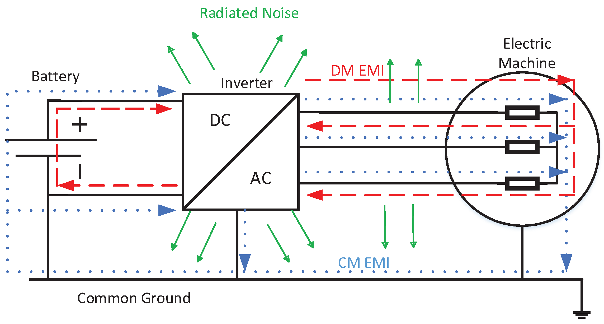
Typically, an electrical drive consists of a power source, an inverter that applies the desired voltage and frequency to the electrical machine, usually with Pulse Width Modulation (PWM) technique and the electrical motor, as shown in
Figure 1. The straight arrows indicate the radiated noise caused by the switching circuits of the converter.
The dashed line represents the differential-mode EMI, which is going through one phase and returns across the other phases to the DC bus of the power source. Finally, the dotted line is the common-mode EMI, which goes across the common ground, connecting all elements to the disturbance [
1].
Even if PWM technique is the most used control technique, its pulses generate a Common-mode voltage (CMV) in the output connection to the motor causing diverse problems such as leakage current, shaft voltage and bearing currents. The rapid voltage changes (high
) also deteriorate the winding insulation and can cause protection failures in the case of short-circuit or contact defects [
2,
3,
4]. Moreover, the generated EMI can affect the power source grid and the elements connected to it, for instance, sensors and safety systems in electric cars [
5].
Specifically, bearings are affected by the CMV variations, as leakage currents flow through them [
6,
7]. Those currents damage the bearings, and together with the winding insulation damage due to voltage stress, the reliability and lifetime of the complete electric drive are decreased.
Some solutions are proposed to mitigate this EMI in electric drives. Different inverter typologies and modulation algorithms are proposed to reduce CM voltage [
1,
6,
8]. Filters and other types of add-ons, such as shields or insulation are also widely used to avoid EMI flowing to the power grid as shown in [
6,
9,
10,
11], but they increase the cost of the drive, as well as the volume and the weight as they are bulky and heavy. Hence, those factors can reduce considerably the competitiveness of the final product on the market, for example, in the electric car.
Thus, to reduce the development cost of the product, an EMI strategy-based design should be added early in the product development cycle to reduce costs and achieve the best solution. Consequently, understanding and predicting EMI noise using high-frequency models during the design stage is essential to manage EMI problems.
According to the literature, the most extended modeling techniques for representing the behavior of electrical machines in high-frequency are based on electrical equivalent circuits or Lumped Parameter Models (LPM). These models consist of electrical circuits that comprise several resistances, inductances, and capacitances. The values of this electrical parameters can be obtained applying different procedures. For instance, by experimental measurements [
12,
13,
14,
15,
16,
17,
18,
19,
20,
21,
22,
23,
24,
25,
26,
27,
28,
29,
30,
31,
32,
33,
34,
35,
36], by analytical calculations considering the main design parameters [
11,
37,
38,
39,
40,
41,
42,
43,
44,
45,
46,
47,
48,
49,
50], by Finite Element Method (FEM) [
28,
39,
51,
52,
53,
54,
55,
56,
57,
58,
59,
60,
61,
62,
63,
64,
65,
66,
67,
68,
69,
70] or even by hybrid methods [
71,
72,
73]. The High-Frequncy LPM models are developed for many purposes in the literature. For example, to analyze the influence of the winding placement and the winding connection on the bearing currents [
32,
57], to analyze the common-mode currents [
73] or to analyze the over-voltages at motor terminals due to modulated supplying voltages [
61]. Although all LPM approaches share the same basis, there are many diversified proposals for accounting for different high-frequency phenomena. In addition, as aforementioned, the calculation of the LPM parameters can be faced in different manners. Therefore, it is identified a lack of a comprehensive review about the analysis tools and methodologies for the study of electrical motors in high frequency, identifying the advantages and drawbacks of the main proposals that can be found in the literature.
As stated before, the final objective is an EMI reduction strategy-based design for electrical machines. To reach that objective, in this paper a comprehensive review of high-frequency behavior of electrical motors is proposed, covering the high-frequency phenomena, the tools available to analyze them accurately and the different existing high-frequency models. Additionally, apart from modeling the machine behavior, it is important to know which design parameters affect the EMC behavior of the motor and how they impact on it, as this is the key to the EMC design optimization. Thus, a review of the influence of different design parameters on the high-frequency behavior of the electrical machine is also collected in this paper. It is concluded that the FEM is the most accurate tool to analyze the high-frequency phenomena in these devices. Nevertheless, there are some analytical methods that may be used, especially for capacitance calculation. It is also found that the most influential design parameter is the winding placement and the impregnation amount, at least for CM currents. However, more research is needed in this area to obtain a valid, broad conclusion for a global EMC optimization design.
The structure of the paper is the following. In
Section 2, the main high-frequency phenomena that arise in electrical machines are described. This paper is focused on conducted EMI, so the radiated EMI are out of the scope of this work. Then, in
Section 3, the three main analysis tools are described and the benefit of each method is outlined, presenting different cases found in the literature. In
Section 4, the modeling of electrical motors is discussed, showing the main models published up to date, with their particular details and differences. In
Section 5, the influence of some design parameters on the EMC performance of electrical machines is analyzed. Finally, in
Section 6, the main conclusions are outlined and the future challenges are pointed out for a proper EMC oriented design.
4. Modeling of Electrical Machines in High-Frequency
In the previous section, three different analysis tools are described for high-frequency electrical machine analysis. From that analysis, some electrical parameters are obtained (L, R, C), to introduce them in different models. In this section, the main models are classified based on their topology, parameter extraction methods and their main characteristics.
Concerning their complexity or size, the models can be classified into two categories. Distributed Parameter Models (DPM) and Lumped Parameter Models (LPM). DPM tend to be more accurate, but they may not be integrated with other system components, as they need intensive computation [
39,
51,
52,
56,
58,
61,
62,
86].
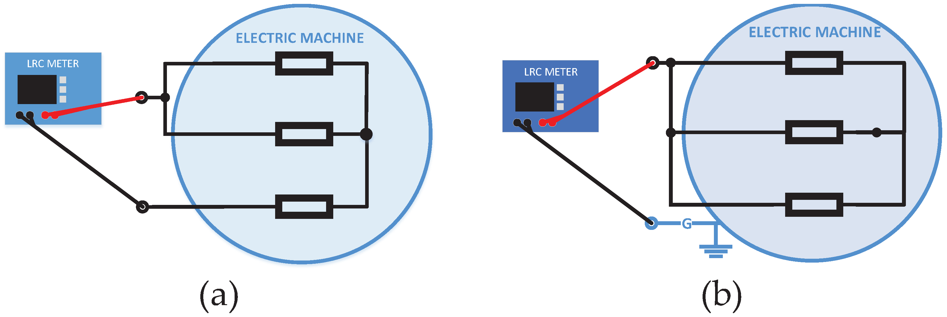
By contrast, LPM is more practical, as it can be introduced in a complete electrical drive model, and its parameters can be obtained from simple impedance measurements [
13,
17,
20,
21,
22,
23,
24,
26,
27,
31,
32,
35,
37,
54,
55,
73]. Some authors develop high accuracy DPM models and simplify it to LPM with matrix reduction methods [
52] or by grouping the RL parameters [
58]. A review of the different models is made in
Table 5.
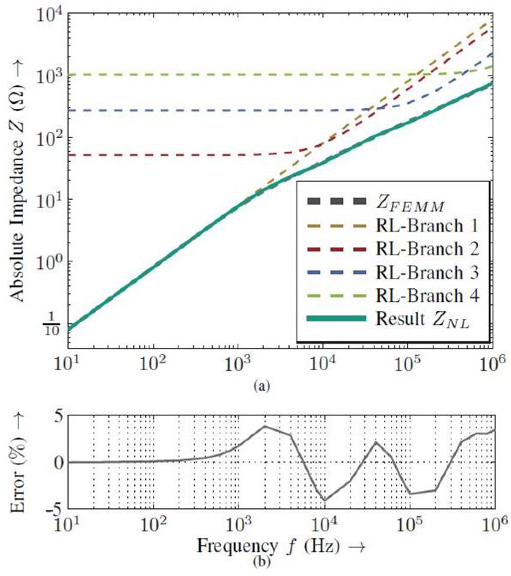
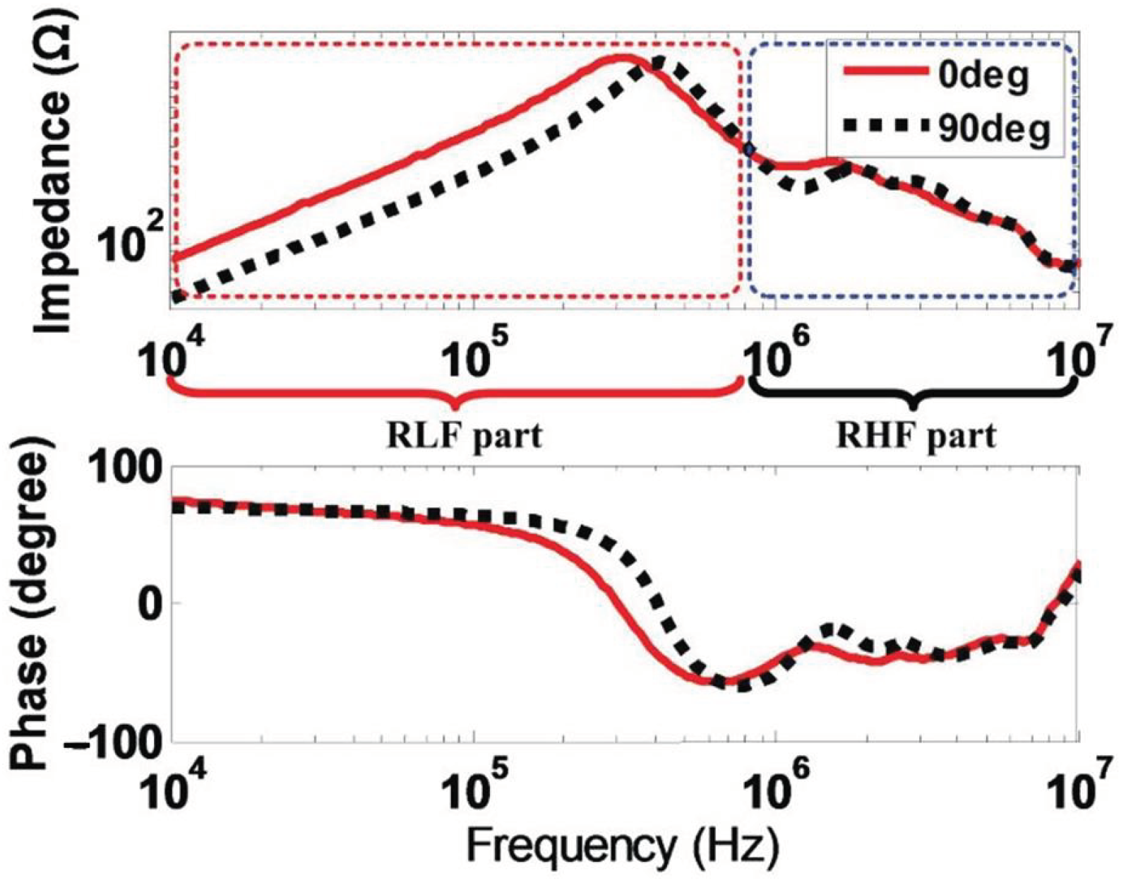
With respect to the simulation domain, some models are working in the frequency domain, for example, to obtain the CM and DM impedance versus frequency. However, to simulate the over-voltages and currents, the time domain is needed. In this domain, the frequency dependency of the parameters is usually considered using lumped parameter circuits, as varying the value for each frequency may not be practical. Two main methods are exposed here.
In [
58] four parallel RL branches are used to reproduce skin and proximity effects in the resistance and inductance values, where each branch represents a frequency range. The resistance of the first branch, representing the low-frequency range is received directly from FEM values whereas the following branch resistances are calculated by a frequency-dependent formula and the decrease of the inductance with the frequency is represented by two empirical factors obtained from [
95]. The resultant impedance is shown in
Figure 9.
Something similar is used in [
22,
26,
28] for taking into account the resistance and inductance variation with frequency. They use Foster’s network, adjusting their values with data fitting procedures. The models are validated obtaining accurate results.
Even if all models are based on LCR circuits, they refer to different parts of the machine and include different high-frequency phenomena:
Inter-turn effects: To make an accurate model in high frequency, the influence between conductors must be modeled. Most FEM-based models consider these effects in the analysis, and in measurement-based methods, this is implicitly included.
Bearing: Just a few models include the bearing in the model, as their capacitance is important when simulating bearing currents, but in the rest of the models they are neglected or calculated analytically [
41] or empirically [
53,
54]. Bearing capacitance can be neglected when using plastic bearings or when the machine is in stand-still as mentioned by [
43,
58]. In [
37] the rotor, the shaft and the bearing models are included, so it is very useful to analyze the motor’s behavior over a wide range of frequencies and it can be also suitable for the study of bearing currents and CM shaft voltage both in time and frequency domain.
Rotor: As
&
are
times smaller than
, the rotor does not affect DM impedance in high frequency, but when analyzing CM current paths, stator-to-rotor capacitance is essential, so modeling the rotor is needed [
37,
58]. A reduction of 16.4% of the maximum over-voltage is found in the case of the turn-to-ground voltage when including the rotor, so it is fundamental for insulation design too [
61]. Additionally, in [
21] a conventional dq Interior Permanent Motor model is improved by adding the ground capacitance, the iron loss resistance and a ground resistance. In this way, the values RL remain constant, regardless of the rotor position, like in the machine models used for control purposes.
Iron Loss: Considering the explained in
Section 2.2, Eddy currents are essential at high frequency. Some models include a loss resistance in parallel with the winding impedance, whereas others do not refer any specific parameter in the electrical circuit to account the losses, being implicit in the circuit values. In [
24], an R in parallel with L and a RC is proposed to account for the Eddy current effect in the iron in the mid-frequency range.
As an example, a distributed parameter turn-by-turn model is proposed in [
62]. The RLC-parameters are derived from 2-D FEM simulations and analytical expressions. It takes into account turn-to-turn capacitance and the capacitance of the iron core. An interesting point of this method is the fact that the circuit is defined in a matrix way, so the calculation of the CM impedance is really fast. It matches the measures until 4 MHz. A similar approach is used to model the resonances and the frequency response in transformer windings using inductance and capacitance matrices in [
96,
97].
It is remarkable that [
31] proposes a high-frequency model in the range of 100 kHz–500 MHz for PMSM in electric vehicles, being able to model the irradiated EMI frequency spectrum including Delta connected stators, but the accuracy of the impedance value at resonant frequencies is limited.
6. Conclusions
In this paper, a thorough review of high-frequency analysis and modeling tools for electrical machines is performed. In addition, the main design parameters that affect to the high-frequency behavior of electrical machines are identified. In this section, the main conclusions are outlined as the results of this review.
First, it should be mentioned that generally the models presented in the literature are not demonstrated to be accurate in the overall range of frequencies covered by EMC standards (from 0 Hz to 30 MHz). All proposals found in the literature show rather good accuracy up to 10 MHz, but not in the range of 10 MHz and 30 MHz. It would be convenient to extend the precision range up to 30 MHz. In addition, the technological development in electronic switching devices are leading to higher working frequencies. Due to the fact that higher precision range above 30 MHz is recommendable because the standard levels might increase as the working frequency of devices increases.
Next, the main conclusions related to every topic reviewed in this paper are summarized.
6.1. High-Frequency Phenomena
In the winding, the skin and proximity effects increase with frequency, affecting both the resistance and the inductance values of the coils. To model those effects correctly, a detailed geometry of the stator slot must be considered, and the location of the conductors inside the slot must be also roughly described. The skin effect depends on the wire diameter and frequency, so it can be eliminated using conductors smaller than the skin depth in parallel strands. However, a high number of strands is counterproductive after a point due to the proximity effect, being also more difficult to manufacture. Litz wires are used to reduce skin and proximity effects, with an especial transposition to reduce the proximity effect, but above a frequency, the proximity effect is not softened.
Regarding the capacitance couplings, the properties of dielectric insulation materials must be precisely known. Otherwise, the computation of the capacitances might differ from real values. It is remarkable than when manufacturing the electric machine, some conductors may vary their position from the theoretical one, making the capacitance calculation differ from the measures too.
Moreover, the end-winding must be also considered, including the skin and proximity effects in that region. Concerning the capacitive coupling, even if the end winding represents less than the 1% of winding-to-stator capacitance, it is up to 40% of the total winding-to-rotor capacitance and it influences the phase-to-phase capacitance, so it must be taken into consideration.
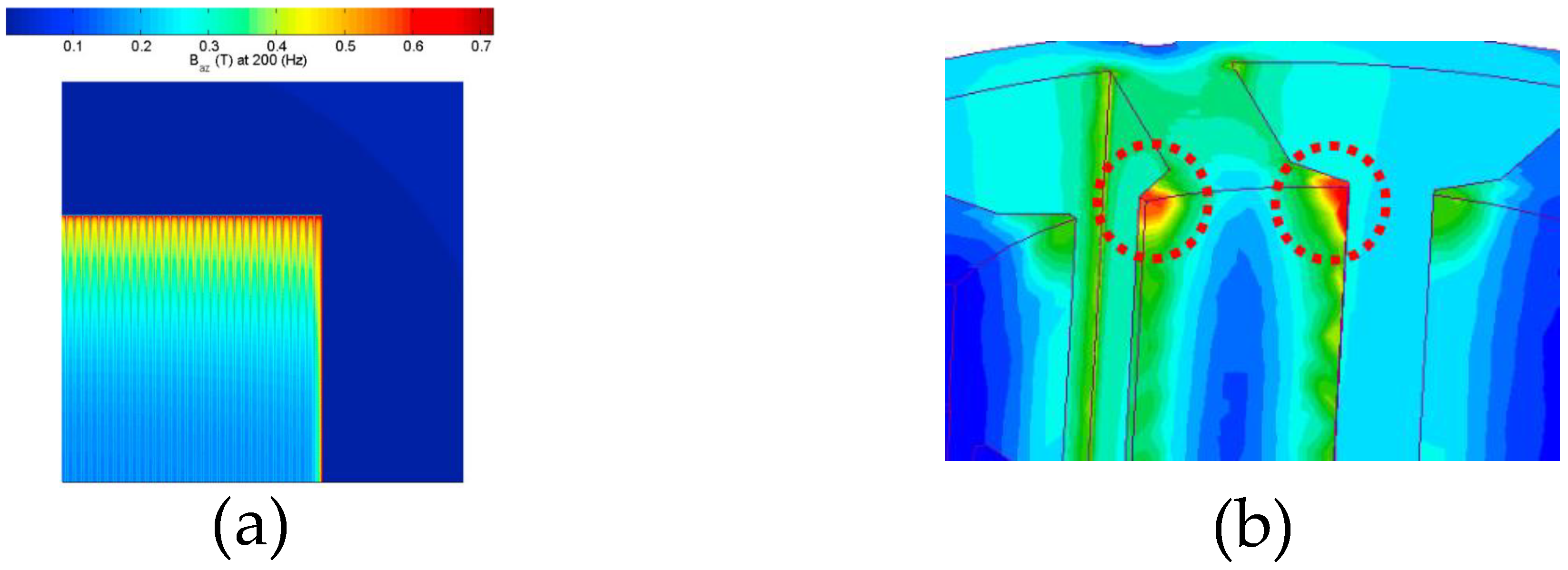
With respect to the magnetic core, Eddy currents are significant in high frequency. Not only due to the iron losses they create, but also due to the shielding effect they produce. Due to this shielding effect, the magnetic flux is pushed out from the magnetic core, decreasing the effective ferromagnetic material area and leading to a decrease in the value of the winding inductance. The frequency when the shielding effect starts depends on the thickness of the sheet and its resistivity. The lamination of the stator prevents the flux being totally pushed out of the core, leading to a higher winding inductance compared to a bulk stator. The effect of lamination also leads to a higher resistance of the winding compared to a bulk core because the surface area where Eddy currents flow is larger and the proximity effect between sheets increases the Eddy currents in the core.
6.2. Analysis Tools
Regarding the FEM analysis, the detailed geometry of an electric machine can be accurately modeled obtaining precise resistance and inductance values, taking into account the skin and proximity effects, as well as eddy current losses in the stator and the capacitive couplings. The mesh of the geometry is essential to obtain accurate results in FEM. When working in high frequency, the skin depth of the materials must be finely meshed, both in the conductors to consider skin and proximity effects, and in the core, as the Eddy currents flow along the skin depth of the iron sheets. Thus, the mesh size must be thinner than the skin depth. However, this meshing requirement leads to a higher time consumption and computational load. Thus, an equilibrium must be found between the model complexity and the accuracy. For the active length of the machine, 2-D simulations are usually used, even if the resistivity of the sheets must be calibrated to take into account the lamination effects, usually using 3-D models. It must be remarked that not all iron sheets comprising the magnetic core can be modeled in 3-D with a mesh size thinner than the skin depth, otherwise, the model will take ages to solve. Commonly, 2 or 3 sheets are simulated and the results are extrapolated to the whole length. Even if the 3-D FEM is the most complete simulation tool, it is the most computationally demanding too, so it is usually only used for the end-winding calculation, as it is the only way to calculate it accurately. Once a 3-D FEM simulation is done, some authors propose different coefficients to take into account this end winding, by using just 2-D FEM for successive simulations. With respect to the capacitance calculation in electrostatic FEM, the same applied to magnetic calculation is applied, needing 3-D models for the end winding, at least for the winding-to-rotor capacitance calculation, where it has a big impact. In this case, a 2 mesh layer must be defined between the conductors for turn-to-turn capacitance accuracy. Gauss Law method is recommended for the calculation of the capacitance matrix, as it requires fewer simulations.
In the case of analytical tools, commonly they require less computation time, as some assumptions and simplifications are considered for each specific case. The skin effect can be easily calculated analytically reducing the effective cross-section area of the conductors. Nonetheless, the computation of the proximity effect is not so simple due to the non-uniform distribution of the magnetic field in the slot. Bessel functions have been used to calculate the AC resistance of the winding, leading to 12% errors at 50 MHz. An analytical method is found to calculate the Joule losses taking into account the proximity losses, but an uniform conductor distribution is assumed in a rectangular slot, so it may not be applicable to all cases, and it is only tested until 1.5 kHz so it may need further development for using it in EMC analysis of electric machines. With respect to the capacitance values, geometric simplifications are done to simplify the calculations to plate capacitors in the case of the winding-to-rotor capacitance or cylindrical ones for the stator-to-rotor capacitance, and even if they converge to the same order of magnitude, they are not accurate enough. A novel approach is proposed for the determination of the winding-to-rotor capacitance using the method of image charges, validating the results with FEM. In the turn-to-turn capacitance, some methods can reach acceptable results. For the turn-to-turn capacitance calculations, the method must be chosen depending on the specific disposition of the winding, otherwise, large errors can appear.
Concerning measurement-based tools, rather good accuracy can be reached by adjusting the model behavior in the whole frequency range. Nevertheless, it is important to underline that this approach is not suitable for the design stage of the motor, as the prototype must be already built to perform the experimental impedance measurements, and then obtain the parameter values by curve fitting. For example, this approach should be suitable for analyzing the behavior of the overall electric drive in simulation, considering the high-frequency models of the motor, the inverter and the EMC filter, but not for predicting the behavior of the electrical machine during the design process. Inside the measured-based tools, there are two different ways of obtaining the electrical circuit model, by looking for the physical meaning of each parameter and relating it to the impedance curve, or just by parameter fitting procedures, obtaining even negative values. This model can obtain excellent accuracy in the whole frequency range.
All in all, FEM tools are recommended for a detailed high-frequency analysis of electrical machines during the design stage. They take into account all high-frequency phenomena and obtain very accurate results provided that the geometry and mesh are properly defined.
6.3. Modeling
The high-frequency models of electrical machines can be classified based on their topology, parameter extraction methods and their main characteristics as well as on their working domain. Distributed parameter models tend to be more accurate, but they are difficult to integrate in the whole electric drive due to the intensive computation required. Lumped parameter models are more used as they are more practical. The values of the LPM are usually calculated from measurements, but there are some DPM obtained from FEM values that are converted to LPM with matrix reduction techniques.
With respect to the simulation domain, some models are working in the frequency domain, for example, to obtain the CM and DM impedance versus frequency. However, to simulate the over-voltages and currents, the time domain is needed. In this domain, the frequency dependency of the parameters is usually considered using RL parallel branches or foster networks, as varying the value for each frequency may not be practical. If frequency-dependent values are obtained from FEM, the equivalent RL branches can be obtained using data fitting methods.
Finally, depending on the objective of the simulation, the developed model may highlight or neglect some parts of the machine. On the basis, all models are RLC circuits, with different number of segments and different physical meanings, but in origin, all refer to winding self and mutual inductances, resistance and parasitic coupling capacitances. The inter-turn effects in the winding are essential to obtain accurate results, whereas the bearing capacitance is just included when the bearing currents are analyzed. The iron losses produced by Eddy currents in the stator sometimes are included as a resistor in parallel with the winding, whereas other times the losses are just implicit in the circuit values.
Concerning the rotor, its influence may be only significant when analyzing bearing currents, shaft voltages, or terminal over-voltage. The rotor position is also important in the low-frequency range for salient pole permanent magnet machines as the inductance changes with the rotor position. Hence, if a full frequency range (0 Hz–30 MHz) model is required, the rotor should be considered.
6.4. Influence of Design Parameters
Different factors may affect the EMC behavior of electrical machines, such as design parameters, manufacturing materials, and fabrication processes and tolerances. To go into detail on the design parameters and tolerances, normally FEM analysis is used as the main option.
Concerning the winding connection, the first resonance frequency of the CM impedance is higher for a Delta connection, whereas the DM amplitude is higher for a star connection. The presence of parallel circuits increases the first resonance frequency to double.
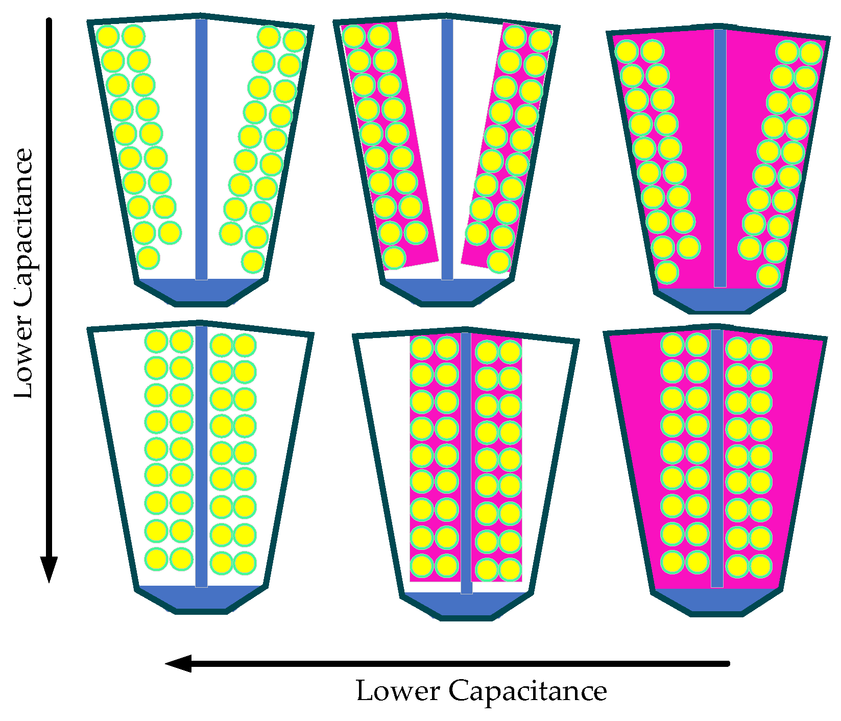
In relation to the conductor placement in the slot, their optimum position is furthest from the rotor, just in the middle of the slot. In this way, winding-to-rotor capacitance is reduced, decreasing the insulation stress, the CM current and the shaft voltage. The capacitances also depend on the impregnation amount. The less the impregnation quantity is, the lower the capacitance is. Moreover, if the strands are aligned with the flux lines, the copper losses will decrease.
Additionally, electrodes can be inserted in the slot wedge to reduce bearing current and the shaft voltage, and shields can be added to the end windings or to the whole machine to reduce the winding-to-rotor capacitance, but these solutions might increase the cost and weight of the machine.
The analysis found in the literature is mainly focused on reducing bearing currents and insulation stress, so a broader approach may be needed to make an EMI strategy-based design for electric machines.
6.5. Future Trends
All in all, a new design methodology should be developed for electrical machines, including electromagnetic, thermal, and EMC optimizing procedures. In this way, the electric drives would be more competitive at the design stage, reducing reworks to comply with EMC requirements. To do so, the explained analysis tools may be combined taking into account the mentioned considerations. First FEM tools must be used to obtain accurate results, then the existing analytical tools may be completed or improved to make faster calculations. Moreover, a more extensive analysis must be performed to identify and quantify the influence of the different design parameters on the EMC behavior of the electrical machines, as this is the key for the optimization.
The present review is the basis to continue developing high-frequency models of electric machines. It gives an overview of the different physical effects that occur at high frequency, together with the different tools to model this phenomenon. The influence of different design parameters in the machine behavior is also summarized. This review is considered to be a necessary contribution to establish a solid foundation for future work in the EMC optimization in electrical machines.


