Article

Compact Ultra-Wideband Series-Feed Microstrip Antenna Arrays for IoT Communications

1
Instituto de Telecomunicações, Campus Universitário de Santiago, 3810-193 Aveiro, Portugal
2
Department of Electronics Telecommunications and Informatics, Campus Universitário de Santiago, University of Aveiro, 3810-193 Aveiro, Portugal
*
Author to whom correspondence should be addressed.
Appl. Sci. 2021, 11(14), 6267; https://doi.org/10.3390/app11146267
Submission received: 18 June 2021 / Revised: 2 July 2021 / Accepted: 5 July 2021 / Published: 6 July 2021
(This article belongs to the Special Issue Design Optimization of Antennas)

Abstract

:
Modern communication systems require high bandwidth to meet the needs of the huge number of sensors and the growing amount of data consumed, and an exponential growth is expected in the future with the integration of internet of things networks. Spectrum regions in the millimeter waves have aroused new interests, mainly because of the contiguous bands available to meet these needs. In return, and to combat the high losses of propagation in these frequencies, higher gain antennas are needed. This paper describes the use of a logarithmic architecture in the design of microstrip antenna arrays, creating structures with high gain and ultra-wide bandwidth. Three different solutions are presented with five, seven, and nine elements, reaching about 25%, 30%, and 44% of bandwidth, achieving ultra-wideband behavior, efficient and with a compact structure operating at frequencies in around 28 GHz.

1. Introduction

The growing evolution of communication systems, culminating with the current deployment of the 5G system, connects the world and its people, being a powerful weapon to reduce inequalities and spread knowledge. Whether 5G or beyond 5G, new challenges are demanded of communication networks to integrate the immensity of users and connected sensors and to share information.
The need to deal with this large amount of data was the decisive factor for the scientific community to look for solutions that would provide free broadband spectrum for the establishment of these networks, which are in the millimeter wave band. These networks that allow people and thousands of sensors dispersed and connected to the Internet, sharing information, interconnected, are today commonly known as Internet of Things (IoT).
Therefore, it is essential that these mobile devices have the ability to handle (transmit and receive) large bandwidths of information, with antennas playing an important role in this context [1].
Antennas are a fundamental component of wireless systems, transmitting and receiving the electromagnetic waves. Microstrip antennas are very popular structures with features that fit modern communications, enabling compact, efficient, and versatile radiating elements with reduced costs. However, in its elementary format, microstrip antennas have features that do not meet the requirements of future communication networks and that must overcome, such as low gain and narrow bandwidth.
New architectures need to be explored so that it is possible to improve their performance, increasing the operating bandwidth, as well as boosting the gain. Microstrip antenna arrays with broadband characteristics have been investigated to address these needs, as well as being integrated into sensors/mobile terminals.
In the literature some works have been developed over the years to improve the bandwidth of an antenna array, some of the most relevant using log-periodic structures [2,3], differentiating in the elements used. Antenna arrays designed with the log-periodic principle present the ability to have wide bandwidth, as well as high directivity and gain. In [4,5,6,7,8,9,10] dipole antenna arrays are identified. For operating frequencies up to 6 GHz, planar structures with several dipoles printed on a dielectric substrate are proposed [4,5,6], typically with one of the dipole arms printed on the top of dielectric surface and the other on the bottom. Variants of this structure, allowing greater bandwidth and operating up to 18 GHz, are proposed in [7,8]. For high frequencies, in [9] an array of microstrip dipoles resonant at 28 GHz and with a compact structure is presented, with about 9 dBi of gain, while in [10] also with a structure printed on substrate, an array of dipoles covering frequencies between 10–40 GHz, with an average gain of 7 dBi, which features a soldered coaxial cable in the antenna structure. An array using bow-tie elements is proposed in [11] also printed on dielectric substrate, for C-band, operating between 6.12–6.58 GHz; however, the results of the radiation pattern and gain obtained were not mentioned.
With a different structure, but using a log-periodic architecture, arrays of printed monopoles are also proposed in [12,13,14]. In [12] authors propose a compact array operating between 8.4–14.6 GHz, with a gain between 6.5 dBi and 9.5 dBi. An array with 15 monopoles, also in a log-periodic structure, is presented in [13], with multiband characteristics, and using a low-cost dielectric substrate. This array covers a frequency band between 1.58–15 GHz with a maximum gain of 9.12 dBi. In [14] the proposed monopole array has an end-fire radiation operating in a band between 6–18 GHz with a gain that varies between 2 and 8 dBi. This antenna shows, however, considerable ground plane dimensions, when compared to the size of the radiating part. Some physical modifications to the typical array of dipoles with log-periodic architecture are presented in [15,16]. In [15] a Koch fractal structure is used in the development of the dipole array, allowing for an increase in the bandwidth and reduction of dimensions. This array was designed for the C and S bands, operating between 2.8 and 6.9 GHz, enabling a gain of up to 8 dBi. In [16] a new configuration is presented, using a helical structure in the design of the dipole arms, allowing the authors to reduce the size of the array about 40%, while still maintaining a broad band operation between 1.87–5.89 GHz with a gain ranging between 5.73 and 7.63 dBi.
These logarithmic structures can also be applied to microstrip patch elements [17,18,19,20]. In [17], a theoretical approach is presented for application of the transmission line model for the design of series fed arrays with log-periodic structure. The authors in [18] propose an array of five microstrip patches designed for a central frequency of 11 GHz, achieving only 11% of bandwidth despite the gain being around 12 dBi. In [19] two forms of feeding are presented, coplanar and microstrip, and two structures of arrays of five elements are compared using these methods and showing that microstrip feeding has a lower bandwidth when compared to the coplanar structure. Additionally, with five elements, an array of microstrip patches is proposed [20], operating between 3.3–4.5 GHz. This structure has the particularity of being reconfigurable, turning ON and OFF each element of the array using PIN diodes, and with that it can change between a broadband operation or tuning between four more restricted bands within this frequency range. The array gain varies between 3 and 6 dBi.
Other approaches have also been presented with application to series-fed arrays in order to increase bandwidth. In [21], a 4-element waveguide slot array for band X is presented, whose bandwidth reaches 12.3%. A series array using eight dielectric resonator elements is proposed in [22] designed to operate at 7.5 GHz. This array has a bandwidth of 38.1%, and a gain of 15.7 dBi, however it incorporates a more complex and bulky structure, using reflector plane. Using slow wave transmission lines, a series-fed architecture for a 10-element array is proposed in [23], achieving 10% bandwidth. A 12-element center-fed series antenna array using a novel coaxial feeding is proposed in [24], designed to operate at 4.9 GHz, for 5G applications. A maximum gain of 19 dBi is achieved, within an impedance bandwidth of 20.5%.
In [25], a patch antenna with symmetrical slits to operate at higher frequency, and then integrated into a 2 × 16 array is presented. Simulated results show that the array operates between 14.7–17.9 GHz, corresponding to an impedance bandwidth of 19.6%. A series-fed mm-wave microstrip array is proposed in [26] for 5G applications, by introducing a series of short stubs to one edge of a microstrip line. A 4 linear has been designed, presenting an impedance bandwidth of 21.40%, with a gain of 12.80 dBi. A 4 × 4 planar array has been also presented with a measured bandwidth of 19.15% and a gain of 18.30 dBi. A novel series-fed array working operating at 5.8 GHz has been proposed in [27] using a dual-band patch resulting from the superposition of two tapered patches with different lengths, specifically designed to solve the problems of reduced bandwidth. The designed antenna shows a fractional bandwidth of 5.92%.
There are other proposed non-series configurations [28,29] for 5G applications, which offer large bandwidths. In [28] a square patch designed for 27.5 GHz is proposed, inserted in metasurface that allows reaching 23.4% of bandwidth with a compact structure. In [29] a Fabry–Perot antenna using a half-wavelength spaced superstrate having a half-wavelength thickness, employed as a partially reflecting surface for high gain and wide impedance bandwidth is presented. Simulated and measured results show that the proposed antennas have a 27.6% bandwidth with a maximum gain of 14.1 dBi.
According to the reported works, it can be seen that log-periodic structures are occasionally used, using different radiating elements. However, they are rarely applied at high frequencies and appropriately designed to allow for high bandwidths, ensuring high gains and compact dimensions, which enable solutions suitable for the present and future of communications, namely in IoT networks.
In this paper three different log-periodic microstrip antenna arrays are designed to operate at a central frequency of 28 GHz but with wideband characteristics and with high gain. Besides the combination of these two properties, these solutions also have reduced dimensions, allowing them to be considered when integrating sensors in IoT networks.
This paper is divided into four sections. In Section 1, the work done in this paper is introduced. Section 2 explains the approaches and methods used in the design of the antenna arrays according to the proposed objectives. Section 3 presents the characterization of the designed structures, in terms of simulation and measured results. Lastly Section 4 and Section 5 present the discussion of the obtained results and reports the main conclusions, respectively.

2. Materials and Methods

In this section the design of the antenna array is explained. Microstrip technology consists of a dielectric material covered in both surfaces by a conductive layer, normally of copper. In one side, typically fully covered, working as a ground plane, while in the other, only partially filled, where the transmission lines and other structures are designed. Microstrip structures were used in this work, because of their low cost of manufacturing and high versatility, and because the antennas built in such technology are compact, lightweight, and highly compatible with simple printed circuit boards [30].
The substrate used was the Rogers RO4350B, with a dielectric constant εr of 3.48, loss tangent of tan δ = 0.0026 and thickness of h = 0.762 mm.

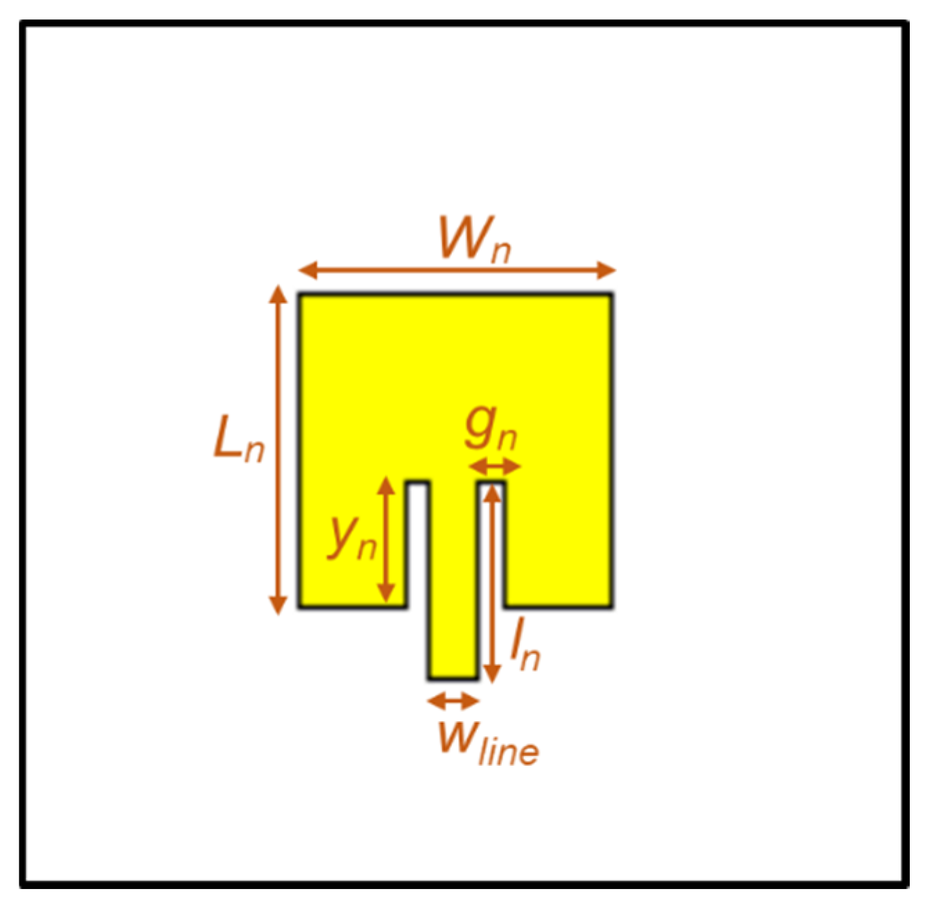
2.1. Design of the Antenna Element

The radiating element chosen is a rectangular microstrip patch for its simplicity of design, and because its resonant frequency is easily controllable by varying its length, L. In this work, in fact, it is a particular case of the rectangular patch, which is a square structure, i.e., W = L, as shown in Figure 1. Another advantage is that it allows the use of inset feeding technique [31], allowing the radiating element to be easily matched to any input impedance, changing the point (yn) where the microstrip line (wline) connects the patch, which will be a huge benefit in this work.
The different parameters that influence the operation of the microstrip patch are identified in Figure 1. They were determined based on theoretical concepts [30], optimized through simulation, and will be detailed later. The characteristic impedance Z0 = 90 Ω for the feeding line (of width wline) was chosen.

2.2. Log Periodic Antenna Arrays

The microstrip antenna elements in essence are not very directive, presenting low gain and very small bandwidth. In order to increase the gain, several microstrip elements were associated in arrays using a series feeding structure as it allows greater compactness. Additionally, a log-periodic configuration was applied in the construction of the array to greatly increase the bandwidth [32].
Antennas with a log-periodic configuration belong to the class of frequency-independent antennas, which theoretically have no bandwidth limitations [32]. In practice the behavior is not independent of the operating frequency, but rather dependent on the logarithm of the frequency. These structures can be seen as a set of adjacent cells, whose dimensions are progressively changed, scaled by a fixed scalability factor, τ.
Taking that into consideration the dimensions of the elementary patch antenna, namely its length (Ln), the width (Wn), the inset feed line and the reentrance (In and yn), the different sizes of the various elements of the array can be estimated through the scalability factor τ as:
τ = L n + 1 L n = W n + 1 W n = I n + 1 I n
These properties imply that the factor of τ relates all operating frequencies
f m + 1 = τ f m = τ 2 f m 1
Considering f1 as a starting frequency, the relationship is as follows, proving the existence of a logarithmic relationship between frequencies.
f 2 = τ × f 1     f 3 = τ 2 × f 1       ln f 2 f 1 = ln τ     ln f 3 f 1 = 2 × ln τ    

2.3. Design of the Antenna Array
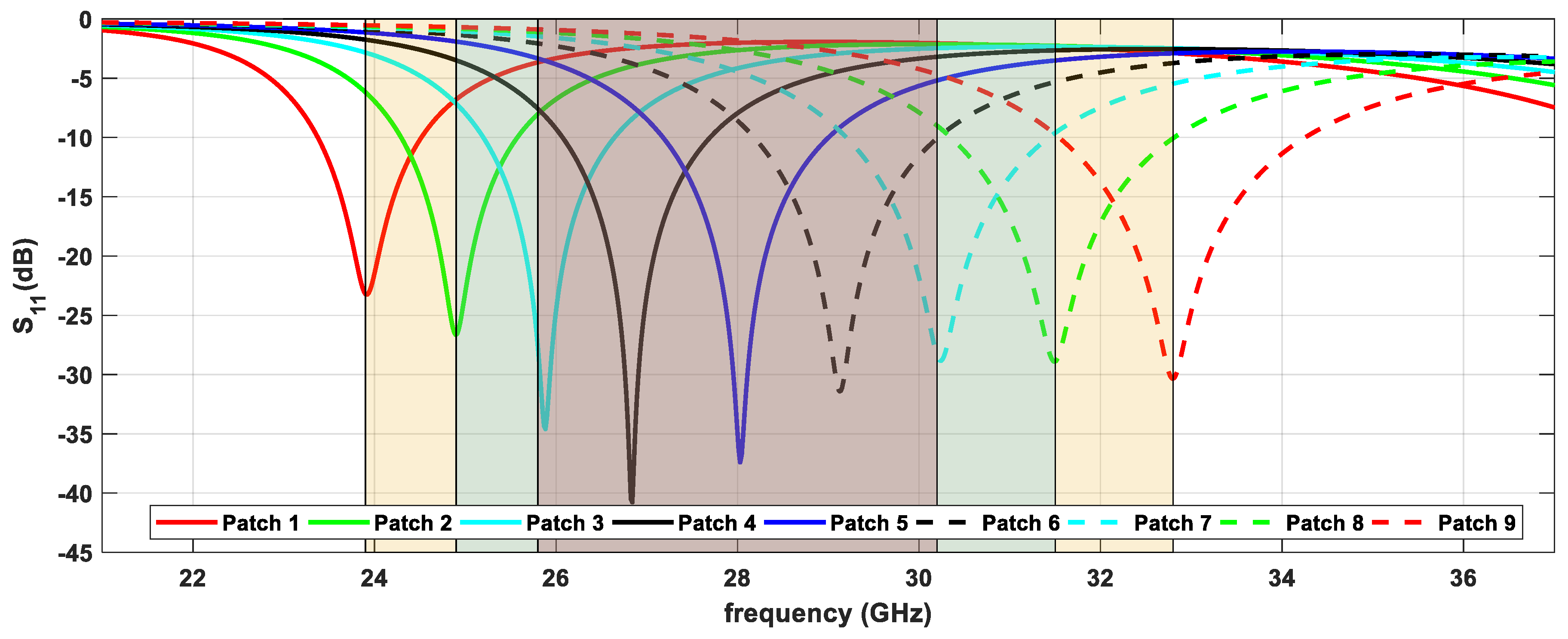
Using the microstrip element before designed, shown in Figure 1, and using the principles stated above about antenna arrays with log-periodic structure, the dimensions for a group of elements were estimated, for a central band of 28 GHz. In this sense, the crucial parameter to find was the scalability factor τ, to ensure a good relationship among the functionality of the antenna, the bandwidth obtained, and the overall size. In this work, bandwidth and size are of special importance, as already mentioned, because they are crucial aspects in emerging communication systems. The scalability factor obtained after some simulations was τ = 1.04. That said, the various dimensions Ln, Wn, In and yn were calculated, as well as the respective resonant frequencies.
Nine elements were considered (i.e., n = 1...9), of which the first four are resonant below 28 GHz, one exactly at this frequency, while the remaining four operate at above frequencies, in such a way that respect the relationship (2). The list of frequencies using this scalability factor is displayed in the second column of Table 1.
In the remaining columns of Table 1, the estimates of the various parameters for each element to operate at each referred frequency are presented, always respecting the relation in (1), and starting from the sizes of the element estimated to operate at 28 GHz (n = 5). Additionally, these dimensions were corrected through simulation and are also shown so that the respective element is resonant at that frequency, as well as the obtained fn.
Figure 2 shows the simulated S11 for each of the resonant elements present in Table 1, where it is possible to identify the respective operating frequency for each patch.
Considering the various elements identified above, designed according to a log-periodic structure, they were grouped into sets of 5, 7, and 9 elements, centered on (and including) patch 5 (fc = 28 GHz), and using them, three series-fed microstrip arrays were created. In Figure 2, it is possible to distinguish different areas shaded with different colors, theoretically limited by the elements that make up each of the three arrays.
Hanging on a transmission line with characteristic impedance identical to the respective impedances of each element (Z0 = 90 Ω), the various patches were arranged and intercalated on each side of the line. This characteristic impedance corresponds to a compromise between the dimensions of the microstrip line, and the impedances of all patches, in order to ensure the structure is small and efficient, as intended.
Regarding the different dimensions of the patches, In corresponds to a quarter-wavelength, the spacing of the gn feeding line does not follow any formula, but requires a minimum aperture that guarantees the proper functioning of the feeding structure. In this sense, it is usually adopted a value half of the feedline width wline.
The only non-periodic parameter is the distance between patches, Dn, illustrated in Figure 3a, and these separations were obtained through an optimization process so that all input impedances are properly associated along the central microstrip line, to obtain an input impedance equal to Z0.
To complete the design of the antenna array, and since the characteristic impedance of the main line is different from the standard 50 Ω, a quarter wavelength microstrip line was added to transform the 90 Ω characteristic impedance to 50 Ω. Although this matching step is essential, this solution in a wideband array is not ideal because only one frequency is fully adapted, instead of the entire band of frequencies. Nevertheless, the use of a quarter wavelength transformer is essential, and since this array has central frequency of operation of 28 GHz, it was designed for that frequency, as shown in Figure 3b.
The different arrays with five, seven, and nine elements were designed following the above conditions, and their final layouts are shown in Figure 3a–c, respectively.
The entire design, simulation and optimization process of the array was performed using the Computer Simulation Technology (CST) software, and the final dimensions of the three arrays are provided into Table 1 and Table 2.

3. Results

The three arrays were fabricated, and the images of the prototypes are shown in Figure 4. In this section their measurement results are presented and compared with simulations.

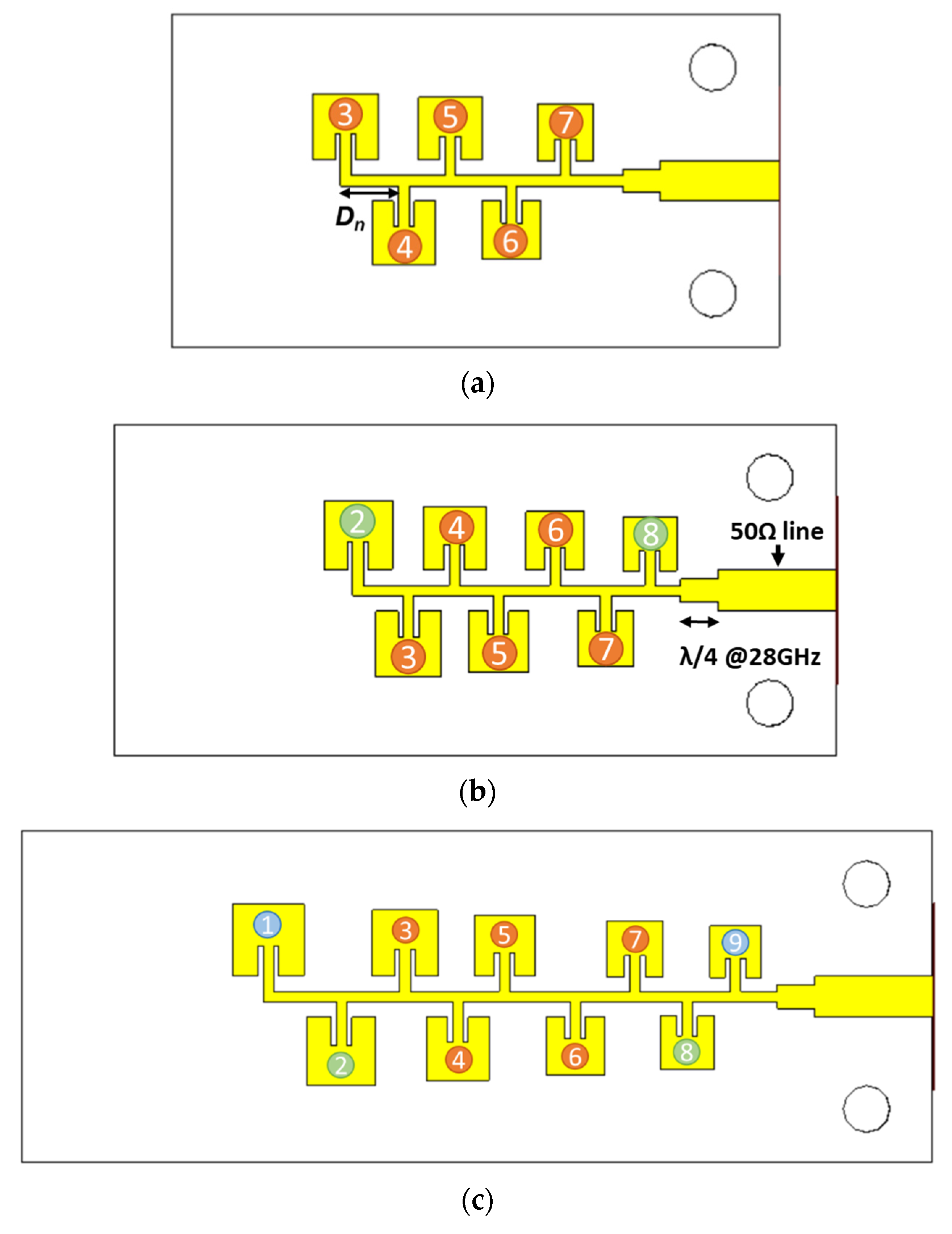
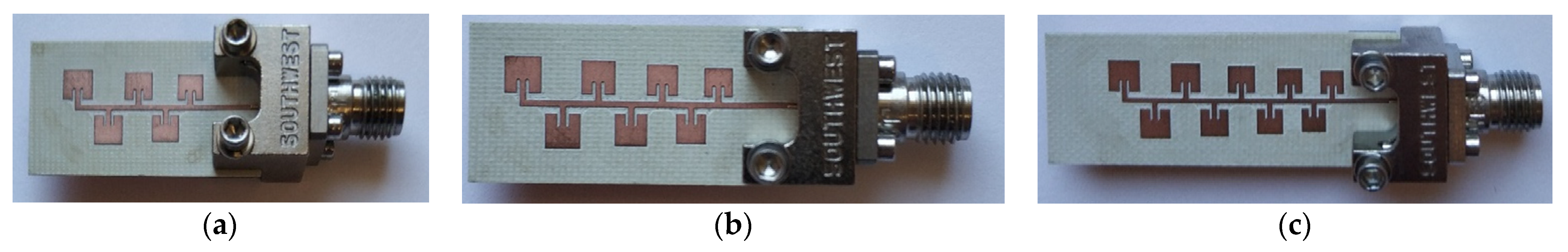
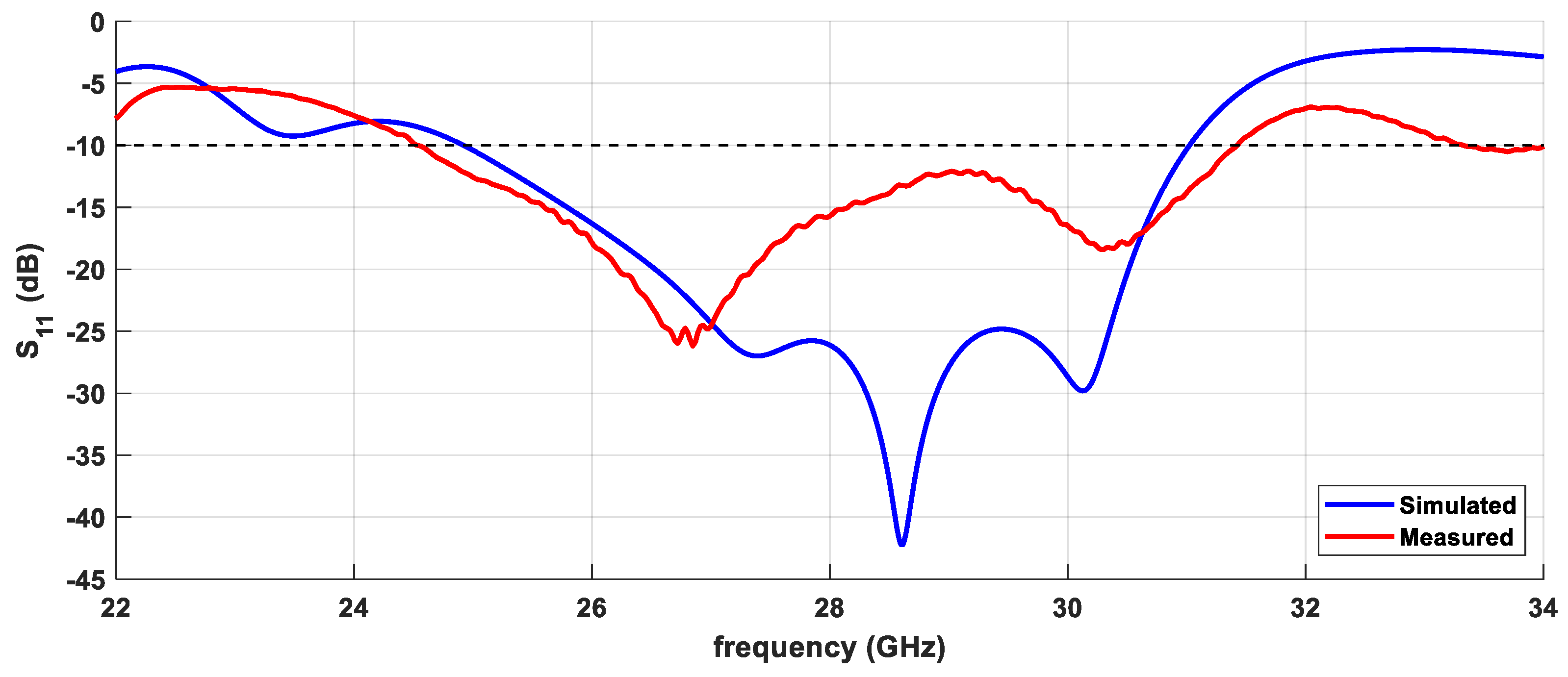
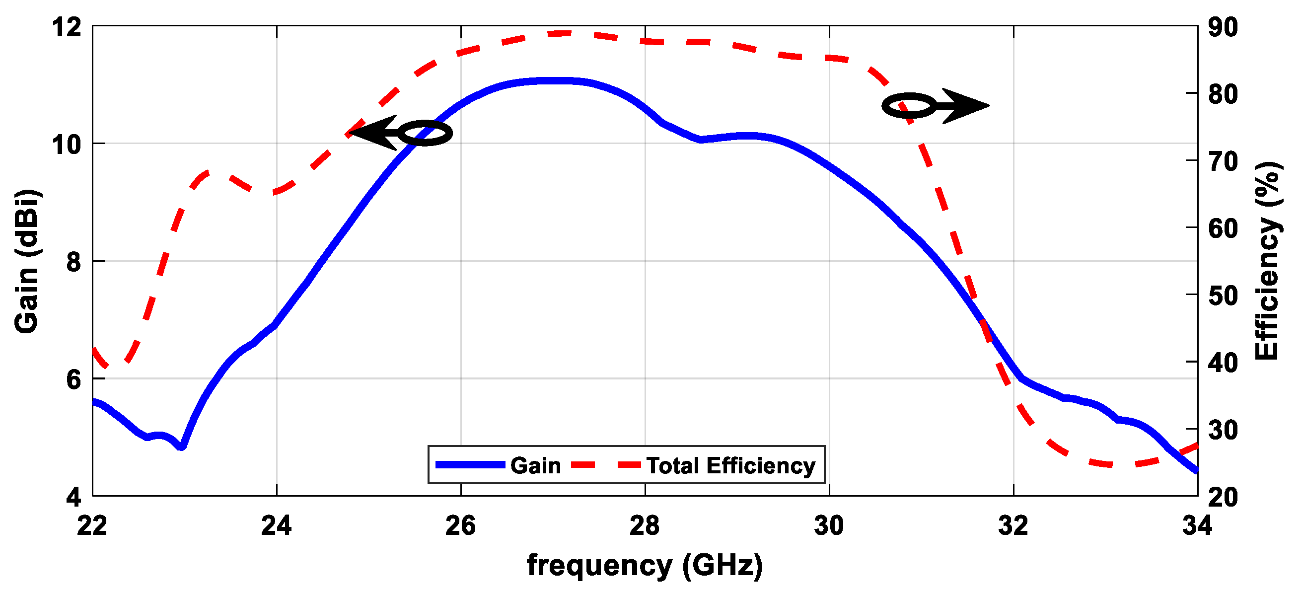
3.1. Five Elements Array

The five-element microstrip array with log-periodic configuration, shown in Figure 4a has global dimensions of 14 × 25.5 mm2, and was characterized in regarding to its main operating parameters, reflection coefficient and radiation pattern.
Figure 5 shows the comparison between the simulated and measured curves of the reflection coefficient (parameter S11). Assuming the common rule of S11 < −10 dB for a good impedance matching, and consequently for considering the operation bandwidth, it is possible to observe that the antenna is well adapted in a 6.91 GHz band, from 24.52 GHz to 31.43 GHz, a little higher than the simulated value (6.1 GHz).
Figure 6 shows the different radiation patterns of the antenna array, simulated and measured, for the two main and orthogonal planes, at three different frequencies within the band, 27 GHz, 28 GHz, and 29 GHz. Despite the reduced size of the antenna, which makes its connector relevant in this type of measurements (and impossible to be removed from them), it is possible to verify that both simulated and measured curves present a similar behavior, practically coincident, allowing to prove the correct functioning of the array in terms of radiation.
The evolution of the simulated gain of the antenna as well as its total efficiency, along the frequency are shown in Figure 7. Regarding the gain, it is possible to verify that it is always higher than 8 dBi in the entire operating band of the antenna, although there is a band from 25.5 GHz to 29.5 GHz where the gain is always greater than 10 dBi, reaching its maximum point around 11 dBi. In terms of efficiency, the antenna has a total efficiency always above 70% in its operating band, mostly between 80% and 90% in the band, which demonstrates that the structure is well designed to operate at these frequencies.

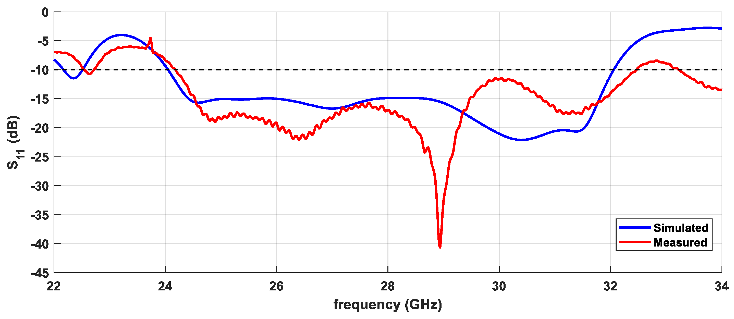
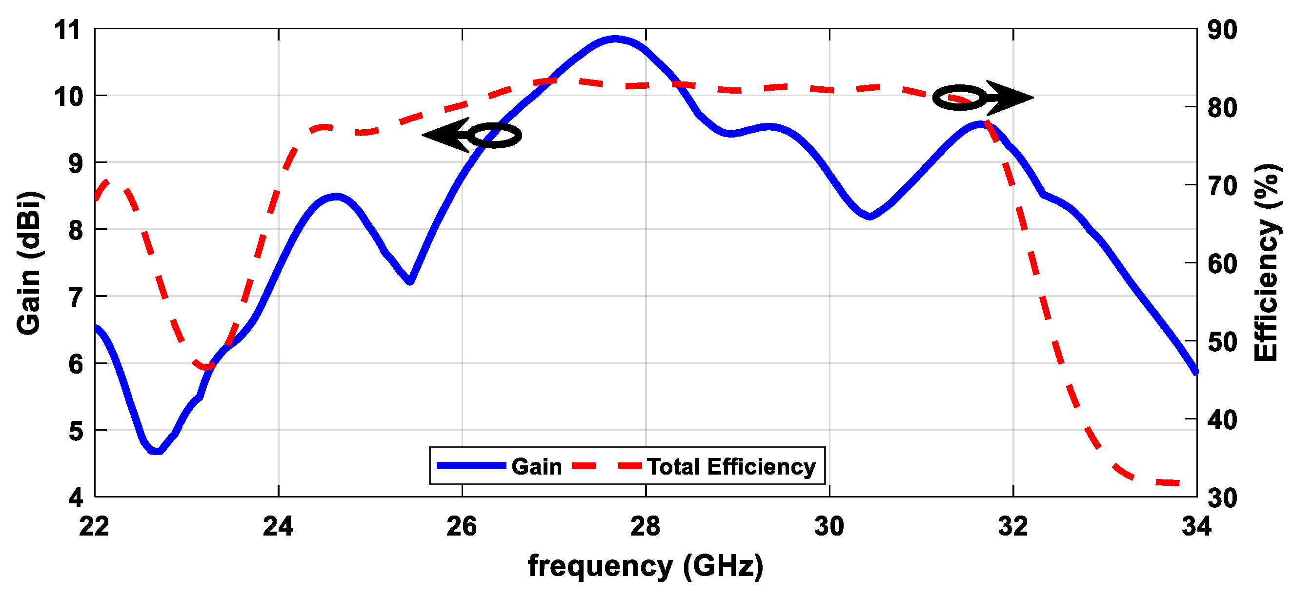
3.2. Seven Elements Array

The seven-element array shown in Figure 4b has total dimensions of 14 × 30.5 mm2, and was also subjected to a set of measurements, with the results being shown below.
The comparison between the simulated and measured S11 curves is shown in Figure 8. It is possible to verify that the array has a measured bandwidth (S11< −10 dB) of approximately 8.3 GHz, from 24.48 GHz to 32.48 GHz, slightly lower than the simulation, centered in the 28 GHz region. In this respect, both curves are similar, and practically across the entire band it is possible to find a value of S11 below −15 dB.
Regarding the radiation patterns, these are shown in Figure 9, for different frequencies. It is possible to verify that in the ϕ = 0° plane, both curves are very close, allowing to clearly identify the main radiation lobe, whereas in the ϕ = 90° plane there are more differences, but it is still possible to define the main lobe clearly on two of the three frequencies. Possibly the impact of the connector on this structure is more evident, functioning as a reflector element.
Figure 10 shows the evolution of both gain and total efficiency over frequency for the seven-element array. It is possible to verify that in terms of the efficiency, it remains relatively stable throughout the band, with a value slightly higher than 80%. Concerning the gain, it already presents more visible variations over the frequency, however being around 9 dBi, in some points rising a little almost reaching 11 dBi, and in others falling slightly; however, in general, results are good, given the reduced dimensions and high operating frequencies.

3.3. Nine Elements Array

In this part, the nine-element array shown in Figure 4c, will be characterized according to its main properties. This array features total dimensions of 14 × 38.5 mm2.
A comparison between simulation and measurements of the reflection coefficient of this antenna is presented in Figure 11. In this figure both curves have a good agreement, and assuming the already defined convention of S11 < −10 dB, this array has an operating bandwidth of 12.2 GHz, from 21.71 GHz to 33.91 GHz, corresponding to almost 44% of the design center frequency.
The radiation pattern at different frequencies, 27 GHz, 28 GHz and 29 GHz is shown in Figure 12. As with the other structures, it maintains a good agreement between simulations and measurements, clearly identifying and defining the main radiation lobe.
Regarding the evolution of gain and efficiency with frequency, the curves are shown in Figure 13. Efficiency has a well-defined and stable behavior between approximately 22 GHz and 33 GHz, always with values above 75%, in some zones on the way to 90%. Relating to the gain, it presents a minimum of 6 dBi in the beginning of the band, but mostly it is better than 9 dBi, reaching very close to 12 dBi around 28 GHz.

4. Discussion

The main results taken from the previous section are compiled in Table 3, for the three developed microstrip arrays with log-periodic structure with five, seven, and nine elements. Regarding the total efficiency parameter, provided at three different frequencies, it is possible to conclude that all arrays are properly designed, using materials with good behavior at high frequencies, since it is possible to observe always high efficiency values, well above the 80%. Likewise, the gain is presented at the same three frequencies. It is possible to observe that the developed antennas have gains mostly in the 10–12 dBi range, which are values considerably higher than those of the typical known elementary antennas; therefore, allowing us to combat propagation issues typical in these frequency bands, improving communications.
Finally, the results regarding bandwidth are shown, as absolute values and also as a fractional value using the fc of 28 GHz considered in the design. The results reveal that with the increase of the number of elements in the array, the bandwidth obtained also increases, reaching almost 44% of bandwidth for the nine-elements prototype. Both antennas, according to [33] are considered ultra-wideband structures.
Table 4 compiles a set of characteristics from a group of selected state-of-the-art papers, which better represent different approaches proposed to enable wider bandwidths using antenna arrays with series configurations. Although it is not possible to make a linear comparison, as they are all distinct and composed of different number of elements, it is possible to find out that the nine-element array proposed in this paper is clearly the solution with the greatest bandwidth, keeping a compact structure.
Lastly, it is also important comparing the results in terms of bandwidth of the proposed arrays with typical series-fed patch antenna arrays. In [34] a 4 × 4 array of microstrip patches operating at 28 GHz is presented, composed of four-element patch series-fed arrays which have an approximate bandwidth of 1.5 GHz, corresponding to 5.35%. In both solutions proposed in this article using log-periodic architecture, it is possible to substantially exceed these values, allowing to achieve bandwidths of 25%, 30% and 44%, respectively, evidencing the advantage of this approach when compared to conventional techniques.

5. Conclusions

In this paper three ultra-wideband log-periodic antenna arrays are presented for IoT communications, combining high gain and efficiencies to the ultra-wideband. The array uses microstrip technology and log-periodic structures, scaled from a central 28 GHz inset-fed patch element. The bandwidths obtained are 6.91 GHz, 8.3 GHz and 12.2 GHz for the five, seven, and nine elements, respectively. The simulated and measured values of the array were compared, and overall, they present a good agreement. Their small and compact structures together with the high gains and efficiencies, makes these arrays good solutions to be incorporated in IoT sensors.

Author Contributions

Conceptualization, T.V., J.C., and J.N.M.; methodology, T.V. and J.C.; software, J.C.; validation, T.V., J.C., and J.N.M.; formal analysis, J.C.; investigation, J.C.; resources, T.V. and J.N.M.; data curation, T.V. and J.C.; writing—original draft preparation, T.V.; writing—review and editing, T.V. and J.N.M.; visualization, T.V.; supervision, T.V. and J.N.M.; project administration, J.N.M.; funding acquisition, J.N.M. All authors have read and agreed to the published version of the manuscript.

Funding

This work is funded by FCT/MCTES through national funds and when applicable co-funded EU funds under the project UIDB/50008/2020-UIDP/50008/2020.

Institutional Review Board Statement

Not applicable.

Informed Consent Statement

Not applicable.

Data Availability Statement

Data sharing not applicable.

Conflicts of Interest

The authors declare no conflict of interest.

References

  1. Iffat Naqvi, S.; Hussain, N.; Iqbal, A.; Rahman, M.; Forsat, M.; Mirjavadi, S.S.; Amin, Y. Integrated LTE and Millimeter-Wave 5G MIMO Antenna System for 4G/5G Wireless Terminals. Sensors 2020, 20, 3926. [Google Scholar] [CrossRef] [PubMed]
  2. Romodin, V.B.; Oznobikhin, V.I.; Kopylov, V.V. Log periodic microstrip array. In Proceedings of the IEEE—Russia Conference. 1999 High Power Microwave Electronics: Measurements, Identification, Applications. MIA-ME’99 (Cat. No.99EX289), Novosibirsk, Russia, 23 September 1999; pp. IV4–IV6. [Google Scholar] [CrossRef]
  3. Rahim, M.K.A.; Gardner, P. Microstrip log periodic antenna using circuit simulator. In Proceedings of the 6th International SYmposium on Antennas, Propagation and EM Theory, Beijing, China, 28 October–1 November 2003; pp. 202–205. [Google Scholar] [CrossRef]
  4. Zengin, F. The Effects of the Trapezoidal Dipole Array Elements on Planar Log Periodic Antenna. In Proceedings of the 2019 IEEE-APS Topical Conference on Antennas and Propagation in Wireless Communications (APWC), Granada, Spain, 9–13 September 2019; pp. 333–336. [Google Scholar] [CrossRef]
  5. Sepdiansah, T.; Mukhlis, Y.; Salam, M.F.A. A Printed Log-Periodic Dipole Array (LPDA) Antenna for 5G Application. In Proceedings of the 2019 Fourth International Conference on Informatics and Computing (ICIC), Semarang, Indonesia, 16–17 October 2019; pp. 1–5. [Google Scholar] [CrossRef]
  6. Tapia-Rodríguez, R.E.; García-Juárez, A.; Noriega-Luna, J.R.; García-Delgado, L.A.; Gómez-Colin, R.; Zaldívar-Huerta, I.E.; Olvera-Cervantes, J.L. Design of Log-Periodic Dipole Array Antenna with Implemmented Extra Dipole. In Proceedings of the 2018 15th International Conference on Electrical Engineering, Computing Science and Automatic Control (CCE), Mexico City, Mexico, 5–7 September 2018; pp. 1–5. [Google Scholar] [CrossRef]
  7. Wang, Z.; Fu, J. A design of miniaturization LPDA antenna with ultra wideband. In Proceedings of the 2015 IEEE 6th International Symposium on Microwave, Antenna, Propagation, and EMC Technologies (MAPE), Shanghai, China, 28–30 October 2015; pp. 819–821. [Google Scholar] [CrossRef]
  8. Kubacki, R.; Czyżewski, M.; Laskowski, D. Enlarged Frequency Bandwidth of Truncated Log-Periodic Dipole Array Antenna. Electronics 2020, 9, 1300. [Google Scholar] [CrossRef]
  9. Sari, P.; Firdausi, A.; Hakim, G.P.N. The Design of Log Periodic Dipole Array Microstrip Antenna at Frequency 28 GHz. In Proceedings of the 2020 2nd International Conference on Broadband Communications, Wireless Sensors and Powering (BCWSP), Yogyakarta, Indonesia, 28–30 September 2020; pp. 140–143. [Google Scholar] [CrossRef]
  10. Benedix, W.; Brandenburg, D.; Dong, X.; Plettemeier, D. Broadband Printed Log-Periodic Antenna with Coaxial Feed. In Proceedings of the 2018 IEEE International Symposium on Antennas and Propagation & USNC/URSI National Radio Science Meeting, Boston, MA, USA, 8–13 July 2018; pp. 841–842. [Google Scholar] [CrossRef]
  11. Didouh, S.; Abri, M.; Badaoui, H.A. A novel design of bow-tie antennas array for uplink C-band applications based on fast and efficient computational equivalent model. In Proceedings of the 2017 Seminar on Detection Systems Architectures and Technologies (DAT), Algiers, Algeria, 20–22 February 2017; pp. 1–6. [Google Scholar] [CrossRef]
  12. Wei, X.; Liu, J.; Long, Y. Printed Log-Periodic Monopole Array Antenna with a Simple Feeding Structure. IEEE Antennas Wirel. Propag. Lett. 2018, 17, 58–61. [Google Scholar] [CrossRef]
  13. Gowda, E.D.; Prasad, V.N. Design of Log-Periodic Monopole Array Patch Antenna for UWB Applications using Alphabetic Slots on Partial Ground Plane. In Proceedings of the 2020 IEEE International Conference on Electronics, Computing and Communication Technologies (CONECCT), Bangalore, India, 2–4 July 2020; pp. 1–5. [Google Scholar] [CrossRef]
  14. Sun, Y.; Liu, Y.; Tang, N.; Xu, D.; Li, Y.; Yu, Y.; Dai, W.; Gou, Q.; Du, Z. The design of wideband end-fire monopole antenna array. In Proceedings of the 2018 International Workshop on Antenna Technology (iWAT), Nanjing, China, 5–7 March 2018; pp. 1–3. [Google Scholar] [CrossRef]
  15. Luong, X.T.; Nguyen, C.T.; Tran, M.T.; Truong, V.B.G. Design a log periodic fractal Koch microstrip antenna for S band and C band applications. In Proceedings of the 2015 International Conference on Advanced Technologies for Communications (ATC), Ho Chi Minh City, Vietnam, 14–16 October 2015; pp. 556–560. [Google Scholar] [CrossRef]
  16. Chen, Q.; Wu, W.; Di, Y.; Hu, Z. A Planar Compact Helical Log-Periodic Array. In Proceedings of the 2018 IEEE International Symposium on Antennas and Propagation & USNC/URSI National Radio Science Meeting, Boston, MA, USA, 8–13 July 2018; pp. 845–846. [Google Scholar] [CrossRef]
  17. Muduli, A.; Mishra, R.K. Transmission Line Model for a Series fed Log-periodic Microstrip Antenna array. In Proceedings of the 2017 14th IEEE India Council International Conference (INDICON), Roorkee, India, 15–17 December 2017; pp. 1–3. [Google Scholar] [CrossRef]
  18. Sharma, D.; Kumar, R. Design and analysis of five element microstrip log-periodic antenna. In Proceedings of the 2010 International Conference on Applications of Electromagnetism and Student Innovation Competition Awards (AEM2C), Taipei, Taiwan, 11–13 August 2010; pp. 210–214. [Google Scholar] [CrossRef]
  19. Veeramani, A.; Dwivedi, R.P. Compartive study of coplanar waveguide feed and microstrip feed for log periodic antennas. In Proceedings of the 2015 2nd International Conference on Signal Processing and Integrated Networks (SPIN), Noida, India, 19–20 February 2015; pp. 10–14. [Google Scholar] [CrossRef]
  20. Ismail, M.F.; Rahim, M.K.A.; Zubir, F.; Ayop, O. Log-Periodic patch antenna with tunable frequency. In Proceedings of the 5th European Conference on Antennas and Propagation (EUCAP), Rome, Italy, 11–15 April 2011; pp. 2165–2169. [Google Scholar]
  21. He, J.; Wu, Y.; Chen, D.; Zhang, M.; Hirokawa, J.; Liu, Q. Realization of a Wideband Series-Fed 4 W 4-Element Waveguide Slot Array in the X-band. IEEE Access 2021, 9, 83666–83675. [Google Scholar] [CrossRef]
  22. Lin, J.; Shen, W.; Yang, K. A Low-Sidelobe and Wideband Series-Fed Linear Dielectric Resonator Antenna Array. IEEE Antennas Wirel. Propag. Lett. 2016, 16, 513–516. [Google Scholar] [CrossRef]
  23. Li, M.; Zhang, Z.; Tang, M.-C.; Yi, D.; Ziolkowski, R.W. Compact Series-Fed Microstrip Patch Arrays Excited with Dolph–Chebyshev Distributions Realized with Slow Wave Transmission Line Feed Networks. IEEE Trans. Antennas Propag. 2020, 68, 7905–7915. [Google Scholar] [CrossRef]
  24. Chu, H.; Li, P.; Zhu, X.-H.; Hong, H.; Guo, Y. Bandwidth Improvement of Center-Fed Series Antenna Array Targeting for Base Stations in Offshore 5G Communications. IEEE Access 2019, 7, 33537–33543. [Google Scholar] [CrossRef]
  25. Boskovic, N.; Jokanovic, B.; Radovanovic, M.; Doncov, N.S. Novel Ku-Band Series-Fed Patch Antenna Array with Enhanced Impedance and Radiation Bandwidth. IEEE Trans. Antennas Propag. 2018, 66, 7041–7048. [Google Scholar] [CrossRef]
  26. Guo, Y.Q.; Pan, Y.M.; Zheng, S.Y. Design of Series-Fed, Single-Layer, and Wideband Millimeter-Wave Microstrip Arrays. IEEE Trans. Antennas Propag. 2020, 68, 7017–7026. [Google Scholar] [CrossRef]
  27. Sacco, G.; Datanasio, P.; Pisa, S. A Wideband and Low-Sidelobe Series-Fed Patch Array at 5.8 GHz for Radar Applications. IEEE Antennas Wirel. Propag. Lett. 2019, 19, 9–13. [Google Scholar] [CrossRef]
  28. Hussain, N.; Jeong, M.-J.; Abbas, A.; Kim, N. Metasurface-Based Single-Layer Wideband Circularly Polarized MIMO Antenna for 5G Millimeter-Wave Systems. IEEE Access 2020, 8, 130293–130304. [Google Scholar] [CrossRef]
  29. Hussain, N.; Jeong, M.-J.; Park, J.; Kim, N. A Broadband Circularly Polarized Fabry-Perot Resonant Antenna Using a Single-Layered PRS for 5G MIMO Applications. IEEE Access 2019, 7, 42897–42907. [Google Scholar] [CrossRef]
  30. Varum, T.; Matos, J.N.; Pinho, P.; Abreu, R. Nonuniform Broadband Circularly Polarized Antenna Array for Vehicular Communications. IEEE Trans. Veh. Technol. 2015, 65, 7219–7227. [Google Scholar] [CrossRef]
  31. Balanis, C.A. Antenna Theory Analysis and Design, 4th ed.; John Wiley & Sons: New York, NY, USA, 2005. [Google Scholar]
  32. Mayes, P.E. Frequency-Independent Antennas. In Antenna Handbook; Lo, Y.T., Lee, S.W., Eds.; Springer: Boston, MA, USA, 1988. [Google Scholar]
  33. Sabath, F.; Mokole, E.L.; Samaddar, S.N. Definition and classification of ultra-wideband signals and devices. URSI Radio Sci. Bull. 2005, 2005, 12–26. [Google Scholar]
  34. Varum, T.; Ramos, A.; Matos, J.N. Planar microstrip series-fed array for 5G applications with beamforming capabilities. In Proceedings of the 2018 IEEE MTT-S International Microwave Workshop Series on 5G Hardware and System Technologies (IMWS-5G), Dublin, Ireland, 30–31 August 2018; pp. 1–3. [Google Scholar] [CrossRef]
Figure 1. Structure layout of an inset-fed microstrip patch antenna with its design parameters.
Applsci 11 06267 g001
Figure 2. Reflection coefficients of the optimized microstrip patch antennas using practical design parameters in Table 1, and frequency zones defined by 5, 7, and 9 elements.
Applsci 11 06267 g002
Figure 3. Designed microstrip antenna arrays using a log periodic structure with (a) n = 5 elements (b) n = 7 elements and (c) n= 9 elements.
Applsci 11 06267 g003
Figure 4. Fabricated prototypes of the log-periodic microstrip arrays: (a) 5 elements, (b) 7 elements, and (c) 9 elements.
Applsci 11 06267 g004
Figure 5. Simulated and measured reflection coefficient of the 5 elements antenna array.
Applsci 11 06267 g005
Figure 6. Radiation pattern of the 5-element log-periodic microstrip antenna array in the two main planes ϕ = 0° and ϕ = 90° for different frequencies: (a) f = 27 GHz, (b) f = 28 GHz, and (c) f = 29 GHz.
Applsci 11 06267 g006
Figure 7. Variation of the Gain and Efficiency of the 5-element array over the frequency.
Applsci 11 06267 g007
Figure 8. Simulated and measured reflection coefficient of the 7 elements antenna array.
Applsci 11 06267 g008
Figure 9. Radiation pattern of the 7-element log-periodic microstrip antenna array in the two main planes ϕ = 0° and ϕ = 90° for different frequencies: (a) f = 27 GHz, (b) f = 28 GHz, and (c) f = 29 GHz.
Applsci 11 06267 g009aApplsci 11 06267 g009b
Figure 10. Variation of the Gain and Efficiency of the 7-element array over the frequency.
Applsci 11 06267 g010
Figure 11. Simulated and measured reflection coefficient of the 9 elements antenna array.
Applsci 11 06267 g011
Figure 12. Radiation pattern of the 9-element log-periodic microstrip antenna array in the two main planes ϕ = 0° and ϕ = 90°, for different frequencies: (a) f = 27 GHz; (b) f = 28 GHz; and (c) f = 29 GHz.
Applsci 11 06267 g012
Figure 13. Variation of the Gain and Efficiency of the 9-element array over the frequency.
Applsci 11 06267 g013
Table 1. Inset-fed microstrip antenna design parameters for a log-periodic structure with τ = 1.04.
nfn (GHz)Ln = Wn (mm)yn (mm)In (mm)Ln = Wn (mm)yn (mm)fn (GHz)
123.932.930.891.923.031.2523.92
224.892.830.831.842.901.1824.89
325.882.700.791.772.781.1125.88
426.922.580.761.702.671.0426.84
5282.460.731.632.560.9828.03
629.122.340.711.562.460.9329.13
730.282.230.681.502.360.8830.24
831.492.130.651.442.270.8431.49
932.752.030.611.382.180.832.81
theoreticalpractical/CST
Table 2. Final optimized distances Dn between elements in the array with 5, 7, and 9 elements.
Dn (mm)D1D2D3D4D5D6D7D8D9
Array 52.441.952.592.272.63
Array 72.141.941.862.402.141.861.52
Array 93.082.662.231.982.992.522.202.051.98
Table 3. Comparison between the main results from the three designed arrays.
Bandwidth (GHz)Fractional BW Bw/fcGain (27 GHz)Gain (28 GHz)Gain (29 GHz)Efficiency (27 GHz)Efficiency (28 GHz)Efficiency (29 GHz)
Array 56.9124.7%11.0 dBi10.6 dBi10.1 dBi88.8%87.7%87.0%
Array 78.3029.6%10.3 dBi10.7 dBi9.40 dBi83.3%82.7%82.0%
Array 912.243.6%11.3 dBi11.7 dBi11.6 dBi84.1%86.8%86.6%
Table 4. Comparison between the different series-fed array approaches.
Ref.N° ElementsFrequency (GHz)Bandwidth (%)Gain (dBi)Size(in wavelengths)
[21]4 × 49.512.3%20.03.8 λ0 × 3.52 λ0
[22]1 × 87.538.1%15.7Not mentioned
[23]1 × 104.510.0%11.03.15 λ0 × 0.6 λ0
[24]1 × 124.920.5%19.09.1 λ0 × 1.3 λ0
[25]2 × 1616.519.6%20.311 λ0 × 1.76 λ0
[26]1 × 427.021.4%12.82.7 λ0 × 0.9 λ0
[27]1 × 65.85.9%14.3Not mentioned
This work1 × 92844.0%12.03.59 λ0 × 1.3 λ0
Publisher’s Note: MDPI stays neutral with regard to jurisdictional claims in published maps and institutional affiliations.

