Article

Use of Granulated Rubber Tyre Waste as Lightweight Backfill Material for Retaining Walls

by
Elizabeth Contreras-Marín
1,
María Anguita-García
1,
Elia Mercedes Alonso-Guzmán
2,
Antonio Jaramillo-Morilla
1,
Emilio J. Mascort-Albea
1,*,
Rocío Romero-Hernández
1 and
Cristina Soriano-Cuesta
1
1
Departamento de Estructuras de Edificación e Ingeniería del Terreno, Escuela Técnica Superior de Arquitectura, Instituto Universitario de Arquitectura y Ciencias de la Construcción, Universidad de Sevilla, 41012 Sevilla, Spain
2
Cuerpo Académico Consolidado CAC-UMSNH-147, Departamento de Materiales de la, Facultad de Ingeniería Civil de la, Universidad Michoacana de San Nicolás de Hidalgo, Morelia 58000, Mexico
*
Author to whom correspondence should be addressed.
Appl. Sci. 2021, 11(13), 6159; https://doi.org/10.3390/app11136159
Submission received: 25 May 2021 / Revised: 24 June 2021 / Accepted: 28 June 2021 / Published: 2 July 2021
(This article belongs to the Special Issue Green Materials and Strategies for an Efficient Building System)

Abstract

:

Featured Application

Applications of recycled rubber tyre granulates as a lightweight fill material in geotechnical work.

Abstract

The use of industrial waste in civil engineering applications constitutes a potential innovative effort to reduce environmental degradation and enable a sustainable use of natural resources. This paper reports a comprehensive laboratory study that was performed to evaluate the rubber granulates from End-of-Life Tyres (ELTs) as a lightweight backfill material in retaining walls. Various tests have been performed to provide specific information on the mechanical and physical properties of a detailed range of particle sizes smaller than 12 mm, with six different particle size distributions (S1: 0.0–0.8 mm/S2: 0.6–2.0 mm/S3: 2.0–4.0 mm/S4: 2.0–7.0 mm/S5: 90% 2.0–7.0 mm + 10% 0.6–2.0 mm/S6: 50% 2.0–7.0 mm + 50% 0.6–2.0 mm). The density and unit weight, compaction energy, compressibility, shear strength, and deformability have been evaluated to determine their performance. As a main conclusion, the research confirms that rubber granulates from ELTs possess great potential as backfill material behind retaining walls. The characteristic values of the geotechnical parameters have been estimated according to Eurocode 7. The friction angle results range from 18.27 to 23.21 degrees, and the cohesion results are wide-ranging, with values from 9.35 to 17.83 kPa. For this reason, two cantilever L-shaped retaining walls, selected as representative case studies, have been tested with these sample properties. The results of the geotechnical verifications are presented together with a comparison of the safety factors in accordance with the Spanish standard design (CTE-DB-SE-C) and the European (EC7-1) regulations. The calculations indicate that the overdesign factors (ODF) achieved in the verifications using the material properties of the S4, S5, and S6 combination improve the calculation results obtained if a conventional filler material such as sand is considered.

1. Introduction

We live in a system where the incompatibility between economic growth and ecological balance is becoming increasingly evident. Aggregates are the second most consumed raw material after water. According to Eurostat [1], 6917 million tonnes of materials were used in Europe in 2019 (14.22 tonnes per capita), with the construction and maintenance of buildings consuming a large part thereof. In general, it can be said that southern European countries tend to recycle relatively little, due to the abundant supply of natural aggregates with suitable quality at low prices [2,3]. There are serious negative consequences of mineral extraction for the environment, such as changes in terrain morphology, surface water, and in air pollution, groundwater contamination, and serious consequences for flora and fauna [4]. Nevertheless, it has been demonstrated that the substitution of recycled aggregates for conventional materials leads to reductions in CO2 emissions. In large-scale projects, reductions can reach more than 50%, obtaining environmental benefits [5].
Nowadays, the USA, the European Union, Japan, and India produce almost 88% of End-of-Life Tyres (ELTs) worldwide [6]. End-of-Life Tyres account for approximately 6.7 million tonnes of waste in the European Union (EU) annually. France, the United Kingdom, Italy, and Spain are responsible for approximately 80% of the European waste production generated by ELTs [7,8]. Considering that 70% of the tyre is rubber [8], it can be stated that around 4.7 million tonnes of rubber granulate is generated annually in the European Union. This makes it important to develop new applications and new markets for this waste.
The ELT Directive (2000/53/EC) [9] is in charge of the management of ELTs in the European Union. Within its regulations, it indicates the selective collection of tyres for their proper management. The directive encourages recycling and, in recent years, has made drastic changes in order to render the management of tyre waste more sustainable. The problems of over-accumulation of industrial waste have become a global problem, especially regarding waste that takes up such large storage spaces as ELTs do [10]. The major issue related to the large areas of tyre storage involves their high flammability and potential risks for the environment and human health [11,12,13]. Disease-carrying mosquitoes can find a breeding ground [14] in the storage of tyres. In order to find solutions to the environmental problems and health threats caused by tyre waste, those countries with the largest industries have a legal framework for its management. Regulations to date have focused on the general characteristics that ELTs must have in the treatment plants. Over the last decades, there has been a marked increase regarding the interest shown in international research into the properties and potential uses for ELTs in sustainable applications [15]. In this sense, ELTs present attractive characteristics in the implementation of civil engineering work and their application has been studied for more than 40 years.
It is well known that the use of industrial waste in geotechnical work produces benefits to the environment, along with the benefits of the particle characteristics and optimal use of each type of waste [6,16,17,18]. Many types of industrial waste are available in large quantities; whether they are used or not generally depends on the lack of proper testing methodology and standards to ensure good performance. Furthermore, there is little experience and diffusion of the implementation and also a lack of financial means, technical equipment, time to develop research work, adequate training, and legislation.
Within this line of work, the use of ELTs has favoured the appearance of research focused on their application as lightweight filling of retaining walls [19,20,21,22]. For such applications, the behaviour of the retaining wall is conditioned by the lateral earth pressure, which is defined by the characteristics of the material (angle of internal friction and unit weight). Cecich et al. [16] used only tyre chips (12 and 50 mm) as a lightweight retaining wall fill and achieved higher safety levels against sliding and overturning compared to those from using sand as a filler. Lee et al. [23] observed that the horizontal pressure on a retaining wall is lower when it is filled with a mixture of tyre shreds (50 and 305 mm) and sand than with a gravel backfill. However, these proposals used ELTs waste containing large size particles.
The following research proposes a new revaluation of rubber granulate in an application that allows a greater impact per cubic metre used, carried out with a detailed range of particle sizes smaller than 12 mm. This approach aims to provide a solution to the problem of over-storage of this particle size in treatment plants. This line of work also enables new uses for granular ELT materials with small particle sizes through a protocol based on the characterisation of mechanical properties in the laboratory of different material combinations and their verification by means of internationally validated calculation methods.
Subsequently, this paper presents the results of the experimental survey for the characterisation of the main properties of granulated rubber. Several samples have been prepared in the laboratory and a variety of tests have been performed in order to quantify their geotechnical properties. First, the tests performed are illustrated and discussed separately Secondly, the characteristic values of the proposed combinations have been obtained by using statistical methods. Finally, safety factors based on EC7-Part 1 (UNE-EN 1997-1:2016) [24] and CTE-DB-SE-C (v2019) [25] are discussed using recycled tyre rubber granulates as lightweight fill and a top layer of half a metre of sand material at the back of a cantilever retaining wall.

2. Properties of Rubber Aggregates

Industrial waste has a completely different composition to conventional soils used as backfill behind a retaining wall, which is why it must be characterised geotechnically in terms of unit weight, angle of friction, and cohesion; the interaction between soil and rubber granulates must also be assessed.

2.1. Classification of ELTs

Traditional soils are usually classified according to the size range of the particles present in the soil, generally referred to as follows: clays < 0.002 mm; silts 0.002–0.06 mm; sands 0.06–2.00 mm; gravels 2.0–60.0 mm. Nevertheless, rubber granulates are classified by the shredding process of the ELTs. In most cases, this is carried out by two or more parallel shafts of blades rotating at different speeds to enable the incorporation of the tyre. The size of the resulting pieces is defined by the separation of the shafts. During the grinding process stages, steel and textile are separated, and the granulated rubber is obtained as a result [8].
The particle size and distribution of shredded tyres can differ, and these materials are called Scrap Tyre Derived (STD) or Tyre-Derived Aggregate (TDA). Rubber shredding systems are established according to the current market demand. The materials produced in the various stages of the treatment processes, mainly through the size reduction of ELTs, can be largely classified in terms of their dimension(s). These are described in ASTM D6270 [26] and presented in Table 1, while Figure 1 shows the particle sizes typically produced for civil engineering applications. Given the limited number of investigations using rubber particles smaller than 12 mm in diameter as a lightweight backfill material for retaining walls, this research is focused on the study of the properties of this class of material, classified as granulated rubber (C).

2.2. Typical Properties of Rubber Tyre Waste

According to Yadav et al., the most interesting properties of TDA include: low material density (1/3 fine-grained soil [6], low lateral earth pressure when it is used as backfill behind a retaining wall (1/2 sand) [27], high permeability for efficient drainage [17,28], and greater thermal insulation than that of gravel (eight times better) [8]. Due to this set of properties and its low unit weight, rubber tyre waste can be considered as a lightweight aggregate [29]. The typical properties of rubber tyre waste are summarised in Table 2 as established in various research studies.
The investigations from Table 2 show an extensive range of particle sizes (0.8 mm to 400 mm). A very limited number of studies have focused on the geotechnical characterization of particle sizes smaller than 12 mm [16,32], making their physical properties and mechanical behavior largely unknown. Additionally, there is no appreciable difference between the results regarding specific gravity. The behaviour against shear strength shows a variation in the results in the samples analysed. The acceptable values of the friction angle are highlighted, but there is low cohesion in the samples, especially in the sand/tyre-chip mixtures. Finally, it can be observed that TDAs show high compressibility: vertical deformations of up to 45% have been observed in the edometric parameters under a tension of 400 kPa [36].

2.3. Rubber Granulate Application

Currently, the European Union possesses no regulations related to the implementation of this type of material. However, in the United States, the ASTM D 6270 standard (“Standard practice for use of scrap tyres in civil engineering applications”) [26] has existed since 1998 and has been updated over time and provides information on geotechnical properties, testing methodologies, and construction recommendations. The ASTM D 6270 addresses the following restrictions: (1) on the fine material that appears with the tyre shreds; (2) the free and exposed steel; (3) the maximum thickness of the shred layer; and (4) limitations on the exposure of tyre shreds to air and water [12].
In 2004, 60 million tyres were used in civil engineering applications, one of the fastest-growing valorisation activities. There are many successful stories, such as that in the state of Oregon (USA) in 2016 in whereby 580,000 shredded scrap tyres were employed in a landslide correction project [30]. Certain research claims that there are cost savings in using shredded tyres (12 and 50 mm) as backfill material: these savings can range from 52 to 67% [16] and depend on the location of project, the demand for natural aggregates, and on other factors, which all have to be evaluated in their implementation.
The advantages of using tyre chips instead of conventional building materials include: reduced density, improved drainage properties, and better thermal insulation [15]. One of the requirements in the assessment of retaining wall fillings involves the horizontal thrust they cause to the wall itself. Considering rubber granulates as a lightweight aggregate could help to reduce the thrust thanks to their low specific weight [29].
It should be mentioned that the ideal backfill material should have high hydraulic conductivity in order to allow free drainage and to prevent any increase of hydrostatic pressures [16].
The addition of crumb rubber to modify bitumen has been utilised to satisfy two needs: on the one hand, to develop high-quality, hot-mixed asphalts; and on the other hand, to reduce the pollution generated by tyre waste [15].
The properties of concrete with rubber granulate mixtures increase compressive and flexural strengths. Research indicates that the toughness of concrete increases with the increase in rubber substitution, whereby 50% and 100% rubber tyre aggregate substitutions exhibit equal values of toughness [37]. Eldin and Senouci [38] reported that when the coarse aggregate is completely replaced by coarse crumb rubber, the strength of the mix decreases drastically: an 85% reduction in compressive strength, and a 50% reduction in tensile strength are observed.
For civil engineering applications, scrap tyres are usually reduced to particle sizes ranging from 12 to 305 mm. Tyre shreds and tyre chips are collectively referred to as tyre-derived aggregates (TDA). From the successful stories in civil engineering applications, the most relevant include retaining walls, lightweight fill for embankments, leachate drainage material for landfills, and layers of insulation under roads.
The need for further research is stressed in order to solidify the conclusions drawn by the researchers [6]. In general, research has focused on the study of crushed sizes between 76 mm to 305 mm, and chips typically ranging from 12 mm to 76 mm. In this sense, this research aims to expose a detailed range of particles smaller than 12 mm, which are generally not detailed in the literature. This will provide a solution to the problem of over-storage of this particle size in treatment plants.

2.4. Conventional Material Mixtures

The main reason for soil modification is for the improvement of the properties of the soil, such as raising its bearing capacity and reducing settlement and lateral deformations. Moreover, the addition of rubber granulates must ensure the correct performance of the mixture, based on the requirements and characteristics needed. Certain studies focus on the behaviour of conventional rubber/arid mixtures in the quest to improve the resulting properties.
Studies on rubber/sand mixtures show that the compressibility of the mixtures rises with the increasing rubber content [39]. The compressibility properties are the same for tests performed under drained or undrained conditions. It should be borne in mind that the grading and type of rubber fail to affect the compression or swelling ratios of the mixtures [40]. Moreover, the void ratio decreases with an increasing tyre-chip content up to a maximum of 30–40%, at which point it then starts to increase [41].
The results obtained in the unconfined compressive strength (UCS) test indicate that the total compression and plastic deformations undergo an increase as the rubber content increases in the rubber/sand mixtures by up to 50%; above this percentage, no significant results are appreciated [27]. It can be observed that the compressibility characteristics remain the same for the tests performed under drained and undrained conditions [28].
According to the analysis of the samples for the parameters of shear strength (friction angle) and deformability (void ratio), the rubber/sand mixtures show optimum substitution percentages of approximately 28 to 30% [41]. Edil and Bosscher [35] characterised mixtures of shredded tyres and sand by varying tyre-chip contents using large-scale direct shear tests; the results highlight the improvement in shear strength. The best performance was obtained at low to intermediate confining pressures.
Mixtures of rubber and clay, whereby clay is substituted with rubber in small amounts (less than 30%), have been shown to decrease the maximum dry unit weight and the corresponding optimum moisture content. Positive dilatancy has been observed during shearing, especially at low vertical pressures [42].
The substitution of conventional aggregates with rubber granulates in brick manufacturing yields benefits in the insulating properties of these elements. Percentages fluctuate between 5% and 11%, depending on the amount of rubber used [43]. The average values of compressive, flexural, and ultimate stresses are inversely proportional to the percentage of rubber crumb substitution. The strengths decrease drastically when the level of rubber replacement increases.

2.5. Assumptions and Limitations

In relation to the costs of production, crushing, and management of ELTs granulate, at a national level, the Spanish Royal Decree 1619/2005 on the management of End-of-Life Tyres (ELTs) indicates that tyre producers will be in charge of the management process, to the extent that the costs attributable to this task are covered. In Spain, these management costs are included in the final selling price of tyres. Consequently, it follows that the costs attributable to the processing of tyre granulate have already been socially assumed compared to the costs of extracting conventional materials.
The most noticeable problem associated with large tire storage areas is the potential fire hazards they present [14]. With regard to the use of this material in geotechnical works, the ASTM D6270 standard provides recommendations on the thickness of the ELTs layers depending on the physical characteristics of the particle used. According to ASTM D6270, this backfill should have on top a layer of granular soil, which prevents the exposure of the rubber granulate to the weather and thus avoiding flammability problems.
Granulated rubber tyre waste has the European Waste Code (EWC) 160103 and is classified as non-hazardous waste. Several investigations carried out in USA since 1989 about the long-term safety of the implementation of ELTs in engineering works, included in the ASTM D 6270 standard [26], have shown that most of the components present in the field study show lower percentages than required by the standards. In addition, most of the substances that could potentially leach from ELTs are naturally present in low percentages in the groundwater [14,44].

3. Materials and Methods

The study was carried out in two stages. For the first stage, the geotechnical properties of granulated rubber were determined, with different nominal sizes, density and unit weight, compaction energy, compressibility, shear strength, and deformability. The results of these geotechnical tests were employed to determine the main mechanical parameters (shear strength modulus and deformability), which are applied in the verification of the stability of retaining walls. The second part of this article presents the analysis of the safety factors based on the EC7-1 standard (UNE-EN 1997-1:2016) and the CTE-DB-SE-C (v2019) with the use of recycled rubber tyre granulates as a lightweight backfill and a top layer of half a metre of sand behind a cantilever retaining wall.

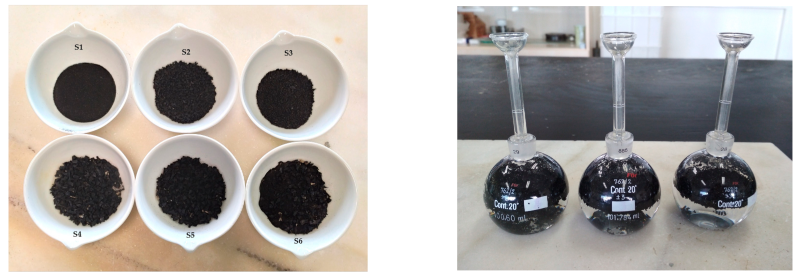
3.1. Preparation of Samples

For the characterisation of the material, a test was carried out in the Soil Mechanics laboratory of the School of Architecture of the University of Seville (US). The equipment had hitherto been used for the characterisation of conventional soils, and no adaptations were made for the tests with rubber granulates. The grain size distribution of the mixtures is defined by the maximum specifications of each piece of equipment. The tests aim to provide specific information on the mechanical and physical properties of six rubber distributions of particle sizes below 12 mm. The evaluated samples of tyre rubber granulate are found to be free of steel and with textile percentages of less than 2%, which is considered to be negligible. Thus, the methodology of fragmentation of the samples and the selection of a homogeneous particle size has been in accordance with the criteria specified in Section 2.1. Classification of ELTs.
According to the research of Strenk et al., tests on small-scale samples can be considered representative of larger TDA particles [12]. This enables a comparison to be made with the studied literature. Hitherto, there has been little information on rubber granulates in the backfill implementation of retaining walls.
Regarding the verified samples, the combinations of 90% 2.0–7.0 mm with 10% 0.6–2.0 mm, and of 50% 2.0–7.0 mm with 50% 0.6–2.0 mm have been proposed in order to evaluate the granulometric influence on mixtures containing rubber granulate sizes below 12 mm.

3.2. Calculation Analysis for the Case Study

In this paper, the evaluation of the case study of a retaining wall is approached, and a comparison is made of the safety factor using tyre granulates as a lightweight backfill and that of conventional material. The main objective is to determine its structural stability and validate the model using the safety factors obtained. The main regulations at national and European level, based on the study of the geotechnical projects, are first briefly analysed in a similar fashion to that of other authors [45,46]. This study assesses and validates various safety factors obtained through each regulation.
The documents considered for this purpose include the Structural Safety Foundation Code from the Spanish Technical Building Code (CTE DB SE-C, v2019) at national level, and the EN 1990-7-2 Eurocode 7: Geotechnical design—Part 1: Geotechnical Project (EC7-1) at the European level. The relevance of this analysis lies in the fact that the Spanish standardisation organism (AENOR) issued the Spanish version of Part 1 of EC7 as a UNE standard in 2010 in order to include the European methodology in the current regulations.

Lateral Earth Pressure

Rankine’s theory has been employed to calculate lateral pressures. This theory analyses the difference in stresses that a soil mass undergoes in its horizontal stress with respect to the vertical stress. The assumptions for this theory are that the horizontal ground surface, the vertical back of the retaining wall, and the backfill are all homogeneous and semi-infinite. For this study, the wall may tilt away from the soil that is retained, and hence the active earth pressure is also considered herein.
According to CTE-DB SE C, and in contrast with EC-7, in the ultimate limit state analysis by means of limit equilibrium methods, the minimum value of the lateral earth pressure considered on the retaining element must be at least 0.25 times the vertical effective stress. This limit mainly affects calculations, since the rubber granulates have a lower specific weight than does conventional material (1/3), and they also present a certain cohesion. For these initial calculations, neither wind overload nor seismic loads have been taken into account.

4. Results and Discussion

The results of the experimental process proposed for the implementation of the research methodology are presented below. In this sense, the two main phases consist of the mechanical characterisation by means of laboratory tests and the verification of the safety coefficients obtained in containment situations using the properties of the proposed material combinations.

4.1. Mechanical Properties

4.1.1. Sieve Analysis and Density

The particle size distribution of the different samples is used in accordance with the UNE-EN ISO 17892-4 [47] to determine the uniformity coefficient Cu (Figure 2). The bulk density measurement is performed in accordance with UNE-EN 1097-6 Annex C [48] in the same way as carried out by other authors for lightweight aggregates with a grain size greater than 4 mm. [49,50,51]. Furthermore, the particle density of the rubber granulates is determined in UNE-EN 17 892-3 [52] by hydrometer analysis. The results are shown in Table 3.
All samples are considered to have a uniform particle-size distribution. The uniformity coefficients are all below three, even for the combined mixtures (S5 and S6), meaning the particles are nearly the same size. The gradation of the different samples is comparable to the gradation of sandy soils commonly used as backfill materials. Smaller rubber granulates result in a lower density compared to that of larger granulates. The results obtained for the density of the tested samples range from 9.79 kN/m3 to 10.32 kN/m3; these values indicate low lateral earth pressure behind the retaining elements using lightweight fillers.

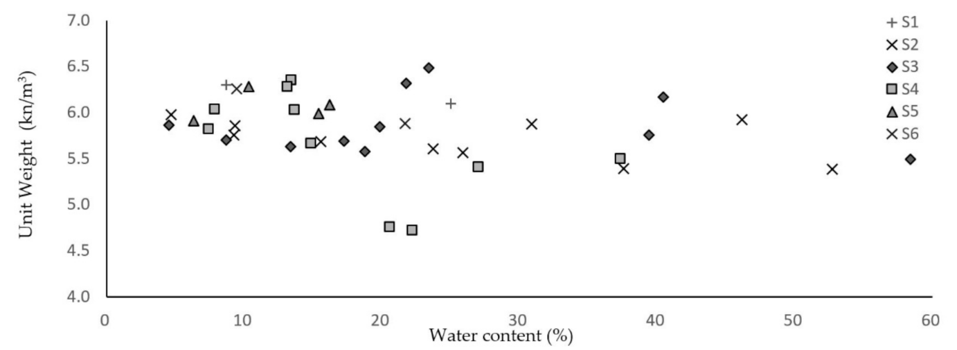
4.1.2. Unit Weight Test

In order to determine the optimum moisture content of the mix and to prepare the samples for unconfined compression and direct shear tests, Standard Proctor tests are performed in accordance with Spanish code UNE-EN 13286-2 [53]. With the results obtained, shown in Table 4, compaction curves are plotted in order to find the maximum dry unit weight and the optimum water content. Nine 5% increments of water content are studied, which are introduced with between 10% and 50% weight of the rubber granulates. The compaction energy (Ee) is difficult to determine due to the high deformability of the rubber granulates.
It can be observed in Figure 3 that increases in water content do not increase the dry unit weight. In none of the six rubber granulate mixtures is a clear trend line observed in the moisture curve, nor can one be found in the drying curve. The different percentages of particles that have been verified and compared reveal similar values, thus establishing a range of values from 5.39 kN/m3 as minimum to 6.03 kN/m3 as maximum. In verifying the retaining wall, 6.03 kN/m3 has been considered.
It is observed that up to a 20% water content helps workability; however, for higher values, the water drains out of the test mould.
The unit weight of soils ranges from 17.55 to 26.77 kN/m3 [16,28,43,54]. Therefore, the unit weight of rubber granulates is less than one third of the unit weight of soils, and hence rubber granulates are considered as a lightweight backfill material in retaining walls.

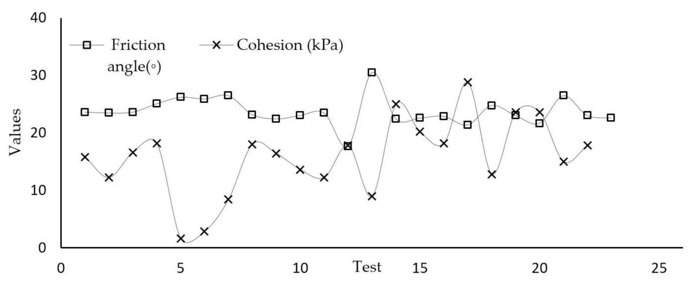
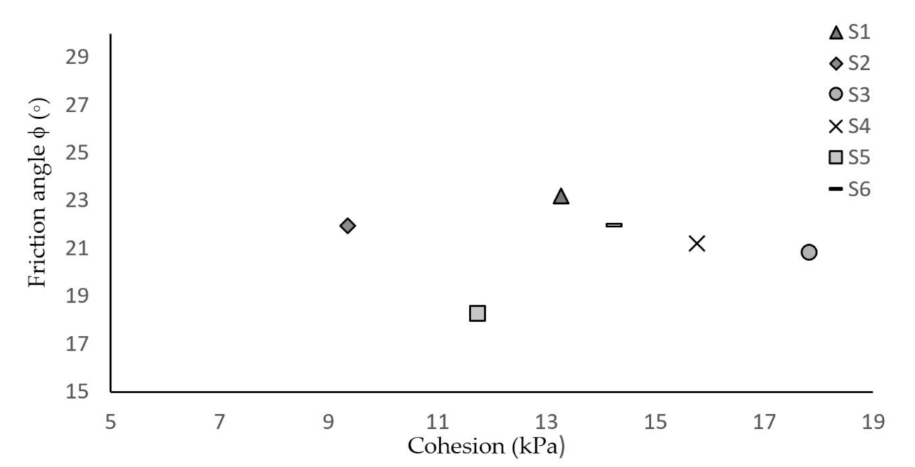
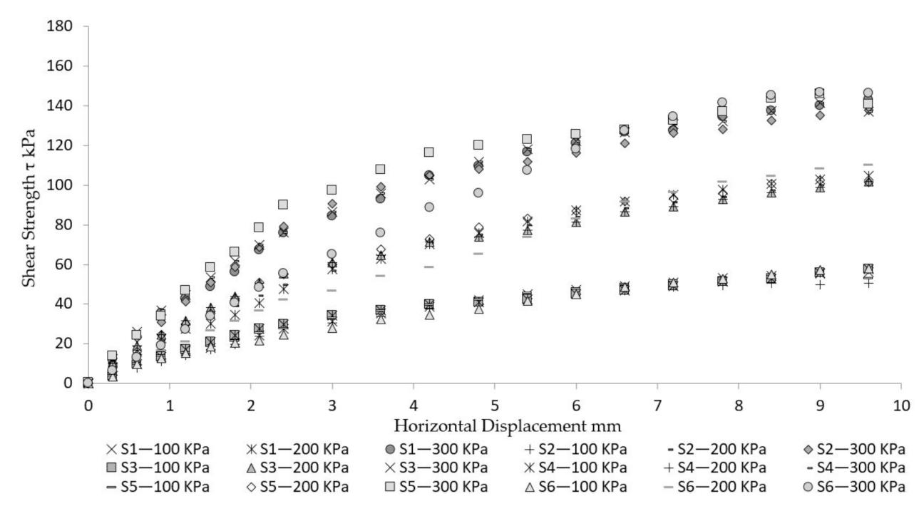
4.1.3. Direct Shear Testing

In order to determine the shear strength of the rubber granulates, direct shear tests are performed in accordance with UNE-EN ISO 17892-10:2018 [55]. Direct shear equipment is employed with circular shear boxes of 50 mm in diameter and of 25 mm in height. Six rubber particle size distributions were tested, for three specimens with different vertical normal stresses: 100, 200, and 300 kPa. Using the Mohr–Coulomb failure criterion, the maximum shear stress that the rubber granulates can withstand is obtained. Since no shear stress peak can be observed, failure is defined as a horizontal deformation equal to 15% of the sample diameter (7.5 mm).
Table 5 shows all the results obtained in these tests, as well as the process of obtaining the characteristic values of each combination of rubber granulates. In this sense, when statistical methods are used, Eurocode 7 (geotechnical design) [24] proposes to calculate the characteristic values of the geotechnical parameters by applying on the mean value of the sample. A normal function is proposed for each of the six samples and the confidence level 1-α = 90% is chosen (α being a value depending on the interval). This results in “conservative estimates” of the population mean value from the mean value with a reliability of 95%. The results of this test are plotted below (Figure 4 and Figure 5).
The characteristic values of the geotechnical parameters have been estimated according to Eurocode 7 [24] (geotechnical design), with a 95% confidence level of the population mean value. The friction angle results range from 18.27 to 23.21 degrees and the cohesion results are wide-ranging, with values from 9.35 to 17.83 kPa.
Figure 6 shows the typical graph of the maximum shear stress versus horizontal displacements with the different percentages of granulated rubber at three normal stresses: 100, 200, and 300 kPa.
The shear strength behaviour shows no variation in the samples analysed. There are no relevant differences between the shear stress curves. It is also observed that, when the normal stresses are increased, there is an increase in shear strength. However, no maximum peak shear strength is observed, and the behaviour is independent of the grain size distribution (Figure 6).

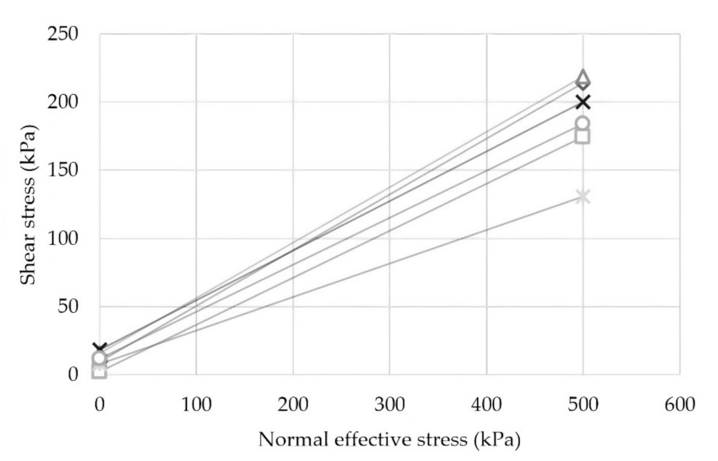
4.1.4. Shear Stress-to-Normal Effective Stress Ratio

Based on the values obtained, the characterisation carried out allows the relationship between the stress parameters of the material to be determined using the Coulomb’s formulation. This question is of great interest in order to achieve a complete mechanical characterisation of the material.
Thus, Figure 7 shows the relationships between the shear stress and the effective normal stress of the selected combinations through the relationships established by Equation (1), where τ is the shear stress, c is the cohesion, σ is the effective normal stress, and ϕ phi is the value of the friction angle:
τ =   c + σ × t g ϕ
The lines in Figure 7 represent the relationship between shear and normal effective stress, shows a higher failure envelope in specimen S3, while specimen S5 has the lowest failure envelope with shear stress values of 218 and 130 kPa, respectively.

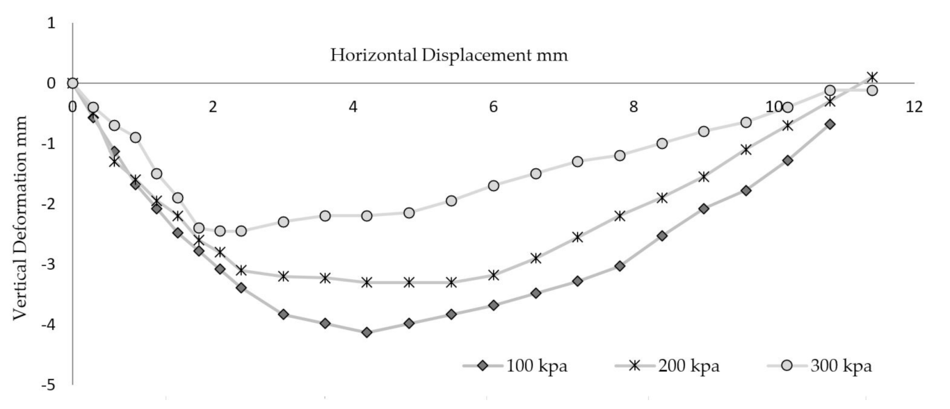
4.1.5. Dilatancy in Rubber Granulates

Complementarily, the analysis of stress/strain behaviour in rubber granulates, can be useful towards understanding the influences of volumetric deformations. It has been found that granular specimens of ELTs exhibit more dilatant behaviour than a soil at peak deviatoric stress, especially at low vertical stresses [56]. Dilatancy decreases with increasing effective confining pressure [18]. The direct shear test fails to allow the quantitative evaluation of the dilatancy, since the unit deformations in the rupture zone remain unknown. However, it is possible to analyse all the deformations in order to ascertain their behaviour. The deformations produced in the direct shear test of the sample S6 are evaluated below (Figure 8).
Shear stresses tend to produce a decrease in volume (negative dilatancy) up to a value of tangential deformation between 1.60% (0.4 mm) and 16.80% (4.2 mm) from where shear stress produces an increase in volume (positive dilatancy). It is found that specimens with low confining compression have high deformations. The specimens with 100 kPa normal stresses deform up to 16.80%, while the specimens subjected to 300 kPa normal stresses have a maximum deformation of 9.60%. Similar behaviour was also reported by R. Fu in 2018 [56].

4.2. Design Criteria of Retaining Walls

The case study that has been the focus of this paper compares the safety factors obtained from an L-shaped cantilever retaining wall. The backfill is a mix of tyre granulates with a top layer of sand as shown below (Figure 9). For geotechnical verifications, the following actions are considered: the weight of the structure itself, the lateral earth pressure, the cohesion, and a surcharge (Q) of 5 kN/m2.
The retaining wall calculations for samples S4, S5, and S6 are developed below, due to how they present greater workability advantages than mixtures with lower granulometry. This will make it possible to determine the degree of influence of the geotechnical parameters obtained on the structural behaviour of the scheme.
Only the drained conditions have been considered for geotechnical verifications. The properties of the materials considered are summarised in Table 6.

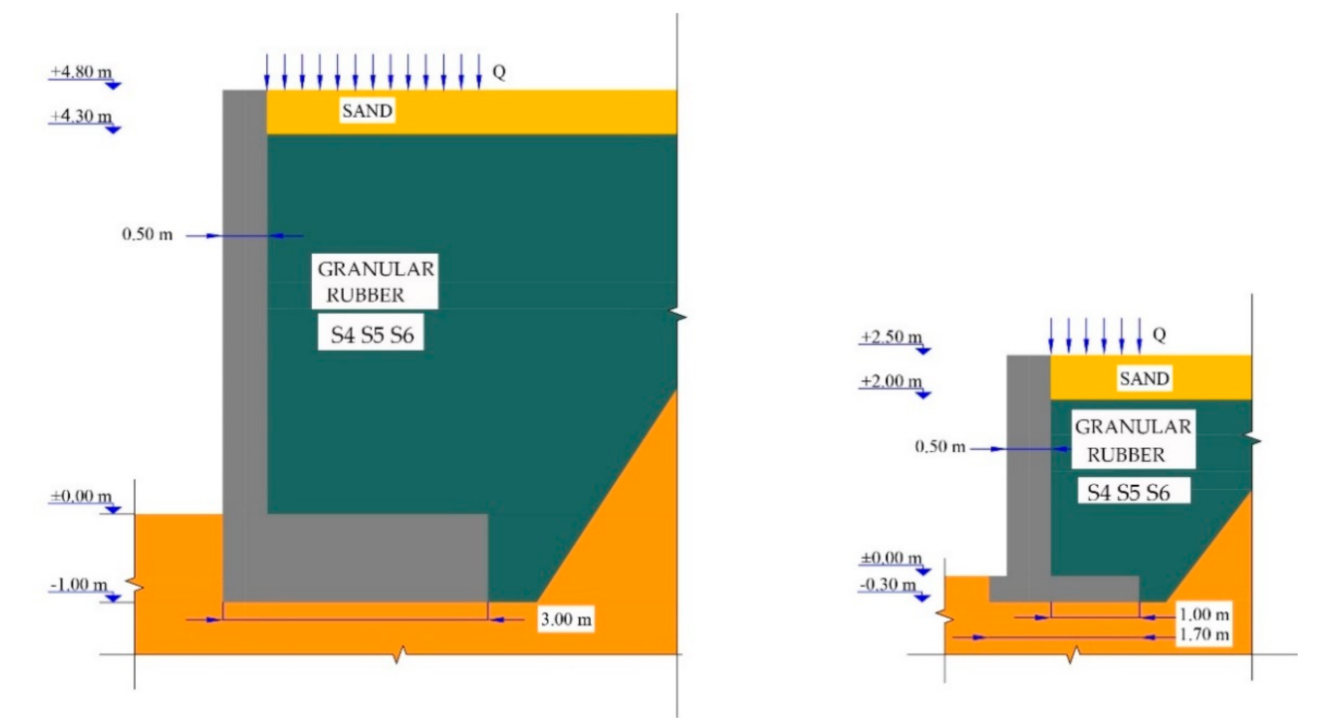
Design Situation and Loads

Resistance to sliding, overturning, and bearing constitute the main geotechnical tests usually carried out on a retaining wall by means of safety factors in accordance with current regulations. For this study case, geotechnical verifications are exclusively considered for a persistent situation, which corresponds to the main condition of use. The safety factors for overturning and sliding are analysed through their evaluation in accordance with CTE-DB-SE-C (v2019) and Eurocode EC7-1 (v2015).
EC7-1 addresses the geotechnical project from the definition of “Limit States” through the use of partial safety factors, which affects the actions, materials referred to as geotechnical parameters, and finally, ground resistance. In this regard, it reveals various “Project Approaches”, which constitute alternative ways of quantifying the uncertainty in the calculation of the limit states by adopting the different partial safety coefficients.
The analysis of the various Project Approaches has led the Spanish National Annex to initially opt for Project Approach 2 for geotechnical actions, except for the calculation of stability and slopes, for which Project Approach 3 is selected.
Project Approach 2 does not undermine geotechnical parameters and is therefore more similar to the usual practices in Spain. However, the major difference between the method used in Spain and that developed in the Spanish National Annex involves the treatment of the actions where they are increased. The disparity of the results obtained, according to Project Approach 2, has led to the development in this test of all Project Approaches with the aim of verifying the ODF factors obtained.
The hypothesis developed determines the overdesign factors (ODF) obtained based on all the EC7-1 Project Approaches and in accordance with the CTE-DB-SE-C for the study of a section of the cantilever retaining wall, as shown in Table 7 and Figure 10. In addition, for a lower section, the same verifications are carried out, as shown in Table 8 and Figure 11.
For the retaining wall of 5.80 m in height, the safety factor for overturning shows an increase between 74.80% and 78.55% in accordance with EC7-1 and 29.82% in accordance with CTE-DB-SE-C with regard to the limit value. As for sliding, a difference between 58.11% and 69.25% is observed between the average of the coefficients obtained in accordance with the design approaches and the limit value for EC7-1, while the coefficient obtained in accordance with CTE-DB-SE-C represents a difference of 25%.
For the retaining wall of 5.80 m in height with sand as conventional material in the backfill, a factor greater than 1.50 is not reached for the sliding safety in accordance with CTE-DB-SE-C, so this solution is not valid. It is observed that the safety factor of 1.00 is not equally reached according to EC7-1, so the section of the retaining wall should be modified.
For the retaining wall of 2.80 m in height, the overturning safety coefficients show an increase with respect to the limit value of approximately between 70.84% and 87.12% in accordance with EC7-1, while, in accordance with the CTE-DB-SE-C, the difference is up to 34.64%. As for sliding, a difference between 47.98% and 57.80% is observed between the average of the coefficients obtained in accordance with the design approaches and the limit value for EC7-1, while the coefficient obtained in accordance with CTE-DB-SE-C shows a difference of 21.87%. For the retaining wall of 2.80 m in height with conventional material in the backfill, a factor greater than 1.50 is not reached for the sliding safety, so this solution is not valid.
In general, the tests show that the properties of the “Sand + S4”, “Sand + S5”, and “Sand + S6” materials are better than those of conventional sand in the case of the tests carried out, as can be seen in the following figures. Consequently, the results show that it is possible to obtain a material with acceptable mechanical and physical characteristics for use in civil constructions.
For the 5.80 m elevation wall, these results show a difference between 58.11% and 69.25% with respect to the ODF limit, while according to the CTE-DB-SE-C the difference is 29.82% with respect to the ODF limit sliding, at least 25% of the vertical stresses are considered to be acting on the back of the wall. In a similar way, it is observed in the values obtained for the ODF for the overturning and for the 2.80 m elevation wall.

5. Conclusions

This paper presents studies on the use of granulated rubber mixtures for their applications in retaining walls. Experimental work is performed in order to determine the geotechnical properties of granulated rubber as a lightweight backfill soil; these properties are subsequently verified in two retaining walls of different dimensions. From this study, the following conclusions can be drawn based on the results obtained:
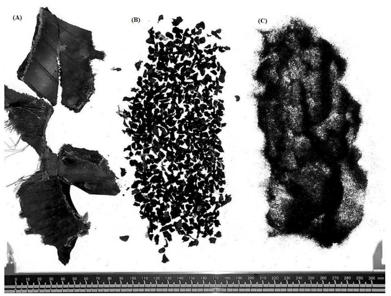
  • Research concerning the use of ELTs as a material in geotechnical works has focused on tyre shreds in a wide range of sizes, ranging from 76 mm to 12 mm. This document provides specific information on the characteristic values of the geotechnical parameters of a detailed range of particle sizes smaller than 12 mm.
  • The results show uniformity coefficients lower than three, even in the combinations of S5: 90% 2.0–7.0 + 10% 0.6–2.0 mm and S6: 50% 2.0–7.0 + 50% 0.6–2.0 mm. These are described as uniform particle sizes. They represent samples where the particle size trend tends to equalise.
  • The density of the samples tested ranged from 9.79 kN/m3 to 10.32 kN/m3.
  • The Proctor Compaction Test was performed on the rubber granulate samples and the maximum dry unit weight obtained was 6.03 kN/m3, which is less than one third of the maximum dry unit weight of a conventional soil.
  • The characteristic values of the geotechnical parameters have been estimated according to Eurocode 7. The friction angle results range from 18.27 to 23.21 degrees and the cohesion results are wide-ranging, with values from 9.35 to 17.83 kPa. According to the values provided by the Table 2, the results obtained are in agreement with the results of the literature reviewed, with values of 3 to 57 degrees and 7.6 to 39 kPa, respectively.
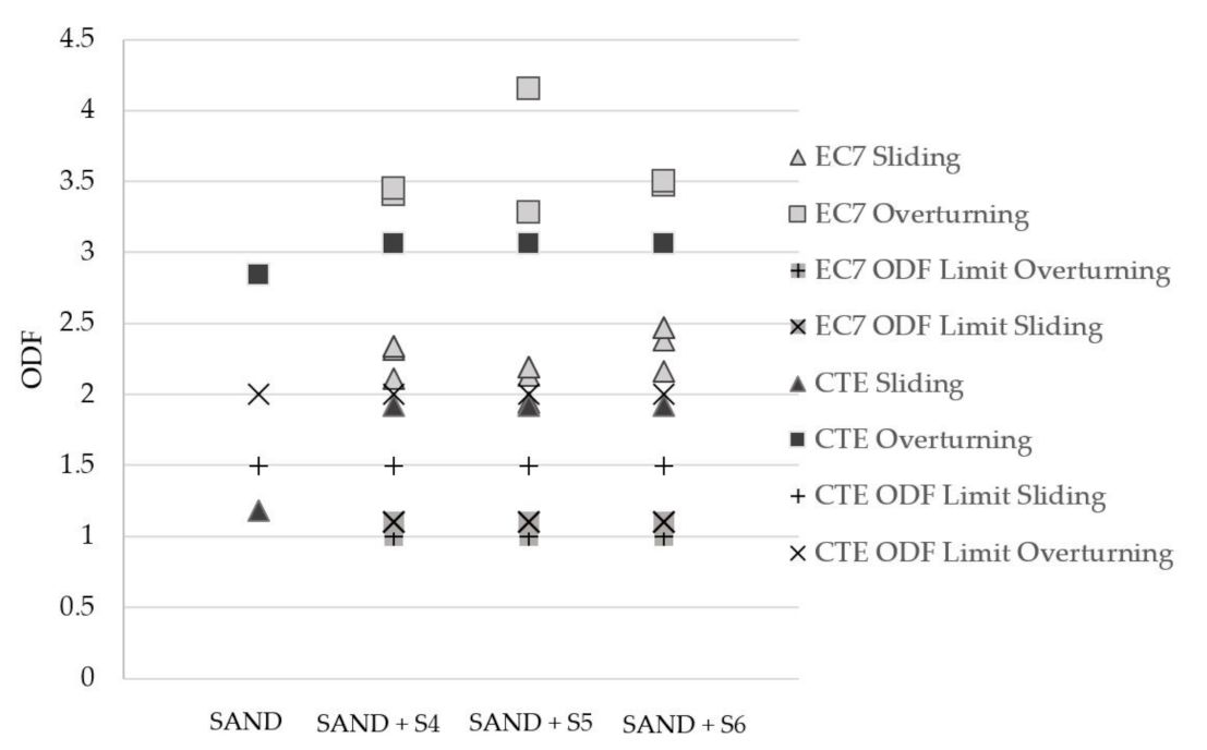
  • The walls of lower height show a greater increase in partial safety coefficients regarding the limit values in accordance with EC7-Part 1, mainly due to the decrease in lateral earth pressure at the back, as a result of the low unit weight and lack of cohesion of the tyre granulates.
  • The comparison between the coefficients obtained in accordance with the various Project Approaches and with the CTE-DB-SE-C shows that the executed procedures fail to provide similar results and that, therefore, the effect that cohesion exerts on the safety coefficients obtained in the calculation should be evaluated, such that they are not so obviously oversized as in the case of EC7-1.
  • No effective differences are observed in the ODF obtained based on the different performing mixes analysed for both the elevation of 5.80 m and 2.80 m in length. Therefore, the choice of performing mix should not be made on the basis of the granulometry.
  • The constructive solutions using granular rubber as filling in the back of the containment walls allow for the optimization of the section of the concrete wall, and therefore, a greater saving in the execution. For the sand type filling, the sliding safety coefficients do not exceed the limit values.

Author Contributions

Conceptualization, E.C.-M., M.A.-G., E.M.A.-G. and E.J.M.-A.; Formal analysis, E.J.M.-A. and R.R.-H.; Investigation, E.C.-M. and M.A.-G.; Methodology, E.C.-M., M.A.-G., E.J.M.-A. and R.R.-H.; Project administration, A.J.-M.; Resources, A.J.-M., E.J.M.-A. and C.S.-C.; Supervision, E.M.A.-G. and A.J.-M.; Validation, E.J.M.-A., R.R.-H. and C.S.-C.; Writing—original draft, E.C.-M., M.A.-G., E.M.A.-G., E.J.M.-A., R.R.-H. and C.S.-C.; Writing—review & editing, E.J.M.-A., R.R.-H. and C.S.-C. All authors have read and agreed to the published version of the manuscript.

Funding

This research has been carried out within the framework of the specific collaboration agreement between the University of Seville and the company SIGNUS. Additionally, the development of this paper has been funded by the Grants for the Internationalisation of Research IUACC 2021 of the VI Own Research and Transfer Plan of the University of Seville (Ayudas a la Internacionalización de la Investigación IUACC 2021 del VI Plan Propio de Investigación y Transferencia de la Universidad de Sevilla).

Institutional Review Board Statement

Not applicable.

Informed Consent Statement

Not applicable.

Data Availability Statement

Data sharing not applicable.

Conflicts of Interest

The authors declare there to be no conflict of interest. The funders played no role: in the design of the study; in the collection, analyses, or interpretation of data; in the writing of the manuscript; or in the decision to publish the results.

References

  1. European Statistical System—Eurostat Domestic Material Consumption Per Capita. Last Update: 05/03/2021. Available online: https://ec.europa.eu/eurostat/databrowser/view/t2020_rl110/default/table?lang=en (accessed on 20 May 2021).
  2. Tam, V.W.Y.; Soomro, M.; Evangelista, A.C.J. A review of recycled aggregate in concrete applications (2000–2017). Constr. Build. Mater. 2018, 172, 272–292. [Google Scholar] [CrossRef]
  3. Söderholm, P. Taxing virgin natural resources: Lessons from aggregates taxation in Europe. In Resources, Conservation and Recycling; Elsevier: Amsterdam, The Netherlands, 2011; pp. 911–922. [Google Scholar]
  4. Stock, J.H.; Bradt, J.T. Analysis of proposed 20-year mineral leasing withdrawal in Superior National Forest. Ecol. Econ. 2020, 174, 106663. [Google Scholar] [CrossRef]
  5. Agrela, F.; González-Gallardo, F.; Rosales, J.; Tavira, J.; Ayuso, J.; Cabrera, M. Complete real-scale application of recycled aggregates in a port loading platform in Huelva, Spain. Materials 2020, 13, 2651. [Google Scholar] [CrossRef]
  6. Yadav, J.S.; Tiwari, S.K. The impact of end-of-life tires on the mechanical properties of fine-grained soil: A Review. Environ. Dev. Sustain. 2019, 21, 485–568. [Google Scholar] [CrossRef]
  7. European Statistical System—Eurostat End-of-life Vehicles: Reuse, Recycling and Recovery. Last Update: 08/02/2021. Available online: https://ec.europa.eu/eurostat/databrowser/view/env_waselvt/default/bar?lang=en (accessed on 16 March 2021).
  8. Grammelis, P.; Margaritis, N.; Dallas, P.; Rakopoulos, D.; Mavrias, G. A Review on Management of End of Life Tires (ELTs) and Alternative Uses of Textile Fibers. Energies 2021, 14, 571. [Google Scholar] [CrossRef]
  9. Parlamento Europeo El Consejo De La Unión EuropeaParlamento Europeo. Directiva 2000/53/CE del Parlamento Europeo y Del Consejo de 18 de Septiembre de 2000 Relativa a los Vehículos al Final de su Vida Útil; EU: Brussels, Belgium, 2000. [Google Scholar]
  10. Boletín Oficial del Estado. Real Decreto 1619/2005, de 30 de Diciembre, Sobre la Gestión de Neumáticos Fuera de uso; BOE: Madrid, Spain, 2006; pp. 352–357. [Google Scholar]
  11. European Tyre and Rubber Manufacturers’ Association ETRMA. End-of-Life Tyre Report 2015; ETRMA: Brussels, Belgium, 2015. [Google Scholar]
  12. Strenk, P.M.; Wartman, J.; Grubb, D.G.; Humphrey, D.N.; Natale, M.F. Variability and Scale-Dependency of Tire-Derived Aggregate. J. Mater. Civ. Eng. 2007, 19, 233–241. [Google Scholar] [CrossRef] [Green Version]
  13. Arroyo, M.; San Martin, I.; Olivella, S.; Saaltink, M.W. Evaluation of self-combustion risk in tire derived aggregate fills. Waste Manag. 2011, 31, 2133–2141. [Google Scholar] [CrossRef]
  14. Cerminara, G.; Cossu, R. Waste Input to Landfills. In Solid Waste Landfilling; Elsevier: Amsterdam, The Netherlands, 2018; pp. 15–39. [Google Scholar]
  15. Topçu, İ.B.; Unverdi, A. Scrap tires/crumb rubber. In Waste and Supplementary Cementitious Materials in Concrete: Characterisation, Properties and Applications; Elsevier: Amsterdam, The Netherlands, 2018; pp. 51–77. ISBN 9780081021569. [Google Scholar]
  16. Cecich, V.; Gonzales, L.; Hoisaeter, A.; Williams, J.; Reddy, K. Use of Shredded tires as Lightweight Backfill material for Retaining Structures. Waste Manag. Res. 1996, 14, 433–451. [Google Scholar] [CrossRef]
  17. Cetin, H.; Fener, M.; Gunaydin, O. Geotechnical properties of tire-cohesive clayey soil mixtures as a fill material. Eng. Geol. 2006, 88, 110–120. [Google Scholar] [CrossRef]
  18. Mashiri, M.S.; Vinod, J.S.; Sheikh, M.N.; Tsang, H.-H. Shear strength and dilatancy behaviour of sand–tyre chip mixtures. Soils Found. 2015, 55, 517–528. [Google Scholar] [CrossRef] [Green Version]
  19. Edil, T.B.; Bosscher, P.J.; Eldin, N.N. Development of Engineering Criteria for Shredded or Whole Tires in Highway Applications; University of Wisconsin-Madison: Madison, WI, USA, 1990. [Google Scholar]
  20. Tweedie, J.J.; Humphrey, D.N.; Sandford, T.C. Tire Chips as Lightweight Backfill for Retaining Walls—Phase II; University of Maine: Maine, Orono, 1998. [Google Scholar]
  21. Anvari, M.; Shooshpasha, I. Fine-grained sand reinforced with granulated tire. Int. J. Recent Innov. Trends Comput. Commun. 2014, 2, 2879–2882. [Google Scholar]
  22. Meguid, M.A.; Youssef, T.A. Experimental investigation of the earth pressure distribution on buried pipes backfilled with tire-derived aggregate. Transp. Geotech. 2018, 14, 117–125. [Google Scholar] [CrossRef]
  23. Lee, J.H.; Salgado, R.; Bernal, A.; Lovell, C.W. Shredded Tires and Rubber-Sand as Lightweight Backfill. J. Geotech. Geoenvironmental Eng. 1999, 125, 132–141. [Google Scholar] [CrossRef]
  24. UNE. UNE-EN 1997-1- Eurocódigo 7: Proyecto Geotécnico Parte 1: Reglas Generales; UNE: Madrid, Spain, 2016; p. 196. [Google Scholar]
  25. Ministerio de Fomento. Documento Básico SE-C CTE-Seguridad Estructural y Cimientos; Ministerio de Fomento: Madrid, Spain, 2019. [Google Scholar]
  26. ASTM. D 6270 Standard Practice for Use of Scrap Tires in Civil Engineering Applications; ASTM: West Conshohocken, PA, USA, 2004. [Google Scholar]
  27. Lopera Perez, J.C.; Kwok, C.Y.; Senetakis, K. Effect of rubber size on the behaviour of sand-rubber mixtures: A numerical investigation. Comput. Geotech. 2016, 80, 199–214. [Google Scholar] [CrossRef]
  28. Madhusudhan, B.R.; Boominathan, A.; Banerjee, S. Engineering properties of sand–rubber tire shred mixtures. Int. J. Geotech. Eng. 2019, 1–17. [Google Scholar] [CrossRef]
  29. Pierce, C.E.; Blackwell, M.C. Potential of scrap tire rubber as lightweight aggregate in flowable fill. Waste Manag. 2003, 23, 197–208. [Google Scholar] [CrossRef]
  30. Federal Highway Administration—Department of Transportation. User Guidelines for Waste and Byproduct Materials in Pavement Construction; FHWA-RD-97-148. Available online: https://www.https://www.fhwa.dot.gov/publications/research%20/infrastructure/structures/97148/st4.cfm (accessed on 16 February 2021).
  31. Jamshidi, R.; Behzad, C.; Mohammad, F.; Akhavan, A.; Alaie, M.R.; Jamshidi Chenari, R.; Maroufi, M.A.A.; Alaie, Á.R.; Fatahi, B. An Experimental and Numerical Investigation into the Compressibility and Settlement of Sand Mixed with TDA Drained constraint modulus H Height of model K 0 “‘At-rest’” coefficient of lateral earth pressure L Width of model. Geotech. Geol. Eng. 2017, 35, 2401–2420. [Google Scholar] [CrossRef]
  32. Tasalloti, A.; Chiaro, G.; Murali, A.; Banasiak, L. Physical and mechanical properties of granulated rubber mixed with granular soils—A literature review. Sustainability 2021, 13, 4309. [Google Scholar] [CrossRef]
  33. Wu, W.Y.; Benda, C.C.; Cauley, R.F. Triaxial Determination of Shear Strength of Tire Chips. J. Geotech. Geoenviron. Eng. 1997, 123. [Google Scholar] [CrossRef]
  34. Rodríguez-Abad, R.; Estaire, J. Geotechnical and environmental properties of tire-used shreds for use in civil construction. In Proceedings of the 6th International Congress on Environmental Geotechnics, New Delhi, India, 8–12 November 2010; pp. 986–991. [Google Scholar]
  35. Edil, T.E. Mechanical properties and mass behavior of shredded tire-soil mixtures. In Proceedings of the International Workshop on Lightweight Geo-Materials (IW-LGM2002), Tokyo, Japan, 26–27 March 2002; pp. 17–32. [Google Scholar]
  36. Li, Z.H.; Zhang, H.Y. Compression Properties of Granulated Rubber-Loess Mixtures as a Fill Materials. Appl. Mech. Mater. 2011, 71–78, 673–676. [Google Scholar] [CrossRef]
  37. Toutanji, H.A. The use of rubber tire particles in concrete to replace mineral aggregates. Cem. Concr. Compos. 1996, 18, 135–139. [Google Scholar] [CrossRef]
  38. Eldin, N.N.; Senouci, A.B. Rubber-Tire Particles as Concrete Aggregate. J. Mater. Civ. Eng. 1993, 5, 478–496. [Google Scholar] [CrossRef]
  39. Kalkan, E. Preparation of scrap tire rubber fiber-silica fume mixtures for modification of clayey soils. Appl. Clay Sci. 2013, 80–81, 117–125. [Google Scholar] [CrossRef]
  40. Fu, R.; Coop, M.R.; Li, X.Q. Influence of Particle Type on the Mechanics of Sand-Rubber Mixtures. J. Geotech. Geoenviron. Eng. 2017, 143, 04017059. [Google Scholar] [CrossRef] [Green Version]
  41. Reddy, S.B.; Krishna, A.M.; Reddy, K.R. Sustainable Utilization of Scrap Tire Derived Geomaterials for Geotechnical Applications. Indian Geotech. J. 2018, 48, 251–266. [Google Scholar] [CrossRef]
  42. Li, S.; Li, D. Mechanical Properties of Scrap Tire Crumbs-Clayey Soil Mixtures Determined by Laboratory Tests. Adv. Mater. Sci. Eng. 2018, 2018, 1742676. [Google Scholar] [CrossRef] [Green Version]
  43. Turgut, P.; Yesilata, B. Physico-mechanical and thermal performances of newly developed rubber-added bricks. Energy Build. 2008, 40, 679–688. [Google Scholar] [CrossRef]
  44. CEDEX. Utilización de Materiales Marginales en Terraplenes en el Sur de España y Norte de Marruecos, y Metodologías para su Aplicación; Ministerio de Transportes; Gobierno de España: Madrid, Spain, 2013. [Google Scholar]
  45. Serrano-Chacón, Á.R.; Mascort-Albea, E.J.; Canivell, J.; Romero-Hernández, R.; Jaramillo-Morilla, A. Multi-Criteria Parametric Verifications for Stability Diagnosis of Rammed-Earth Historic Urban Ramparts Working as Retaining Walls. Appl. Sci. 2021, 11, 2744. [Google Scholar] [CrossRef]
  46. Estaire, J.; Pardo, F.; Santayana, D.; Perucho, Á. Anejo Nacional Español del Eurocódigo 7; CEDEX: Madrid, Spain, 2016. [Google Scholar]
  47. UNE. UNE-EN ISO 17892-4:2019 Investigación y Ensayos Geotécnicos. Ensayos de Laboratorio de Suelos. Parte 4: Determinación de la Distribución Granulométrica; UNE: Madrid, Spain, 2019; pp. 1–31. [Google Scholar]
  48. UNE. UNE-EN 1097-6:2014. Ensayos para Determinar las Propiedades Mecánicas y Físicas de los Áridos. Parte 6: Determinación de la Densidad de Partículas y la Absorción de Agua; UNE: Madrid, Spain, 2014. [Google Scholar]
  49. Concepción, M.; Menor, P. Materiales Sostenibles. Refugo de Corcho como Árido Ligero en Piezas de Hormigón Para Fábrica de Albañilería. Ph.D. Thesis, Universidad de Extremadura, Extremadura, Spain, 2016. [Google Scholar]
  50. Kyser, D.; Ravichandran, N. Properties of chipped rubber roofing membrane and sand mixtures for civil engineering applications. J. Build. Eng. 2016, 7, 103–113. [Google Scholar] [CrossRef]
  51. Contreras-Marín, E.; Anguita-García, M.; Alonso-Guzmán, E.M.; Jaramillo-Morilla, A.; Mascort-Albea, E.J.; Romero-Hernández, R. Mechanical properties of scrap tyre derived-aggregates: Standard and modified proctor tests. In REHABEND 2020 on Construction Pathology, Rehabilitation Technology and Heritage Management; Universidad de Granada: Granada, Spain, 2020; pp. 1523–1534. ISBN 9788409178735. [Google Scholar]
  52. UNE. UNE-EN ISO 17892-3:2018 Investigación y Ensayos Geotécnicos. Ensayos de Laboratorio de Suelos. Parte 3: Determinación de la Densidad de las Partículas; UNE: Madrid, Spain, 2018; pp. 1–22. [Google Scholar]
  53. UNE. UNE-EN 13286-2 Métodos de Ensayo para la Determinación en Laboratorio de la Densidad de Referencia y el Contenido o en Agua. Compactación Proctor; UNE: Madrid, Spain, 2011. [Google Scholar]
  54. Edil, T.B. Use of Scrap Tires in Civil and Environmental Construction; Department of Civil and Environmental Engineering University of Wisconsin-Madison: Madison, WI, USA, 2008. [Google Scholar]
  55. UNE. UNE-EN ISO 17892-10:2019 Investigación y Ensayos Geotécnicos. Ensayos de Laboratorio de Suelos. Parte 10: Ensayos de Corte Directo; UNE: Madrid, Spain, 2019; pp. 1–23. [Google Scholar]
  56. Fu, R.; Baudet, B.A.; Madhusudhan, B.N.; Coop, M.R. A comparison of the performances of polypropylene and rubber fibers in completely decomposed granite. Geotext. Geomembr. 2018, 46, 22–28. [Google Scholar] [CrossRef]
Figure 1. Examples of TDA used. The letters used in the designation correspond to the classification provided by ASTM D6270: Tyre chips (A), granulated rubber (B), powdered rubber (C).
Applsci 11 06159 g001
Figure 2. Left-hand side. Distribution of the samples. S1: 0.0–0.8 mm/S2: 0.6–2.0 mm/S3: 2.0–4.0 mm/S4: 2.0–7.0 mm/S5: 90% 2.0–7.0 mm + 10% 0.6–2.0 mm/S6: 50% 2.0–7.0 mm + 50% 0.6–2.0 mm. Right-hand side. The particle-density analysis of the rubber granulates.
Applsci 11 06159 g002
Figure 3. Optimum water content and maximum dry unit weight.
Applsci 11 06159 g003
Figure 4. The influence of the rubber granulate size on the strength parameters.
Applsci 11 06159 g004
Figure 5. Relationship between cohesion and friction angle of the granulated rubber.
Applsci 11 06159 g005
Figure 6. Variation of shear stress with horizontal displacement of various rubber granulometries.
Applsci 11 06159 g006
Figure 7. Relationship between the shear stress and the effective normal stress of the granulated rubber.
Applsci 11 06159 g007
Figure 8. Vertical deformation curves for S6.
Applsci 11 06159 g008
Figure 9. Schema of the case study: (1) L = 5.80 m; (2) L = 2.80 m.
Applsci 11 06159 g009
Figure 10. ODF sliding and overturning versus schemas of the case study in the 5.80 m retaining wall.
Applsci 11 06159 g010
Figure 11. ODF sliding and overturning versus schemas of the case study in the 2.80 m retaining wall.
Applsci 11 06159 g011
Table 1. ELTs classification by size in accordance with ASTM D6270 [26].
ProductSize
Whole tyreUnprocessed
Tyre shreds (A)Between 50 and 305 mm
Tyre chips (B)Between 12 and 50 mm
Granulated rubber (C)Between 425 μm (40 mesh) and 12 mm
Powdered rubber (D)Below 425 μm (40 mesh)
Table 2. Summary of properties of rubber tyre waste.
Nominal Sizes/Particle
Range (mm)
Specific
Gravity
Unit Weight
(kN/m3)
Mohr–Coulomb ParametersYoung’s
Modulus E (kPa)
References
Cohesion (kPa)Friction
Angle ϕ (°)
25–501.1–1.33.2–7.17.6–11.519–25770–1250[30]
≤12-5.687.0427-[16]
201.25.8---[31]
≤101.1–1.34–9032-[32]
5.742
8.145
21.1--44450–820[33]
9.51.250350–600
191.154430–580
381.157580–690
251.3-15.026.5200–1400[34]
507.034
10010.029
0.8–20-4.9–5.96–3221.6-[12]
10–505.1–6.411–383.3–25.4253–485
20–4004.7–6.319–394.3–13.2130–373
12–50-5.90.030-[35]
Sand—10% 12–5015.62.046
Sand—20% 12–5014.52.050
Sand—30% 12–5013.32.052
Table 3. D10, D60, Coefficient of uniformity (Cu); apparent density (ρLa); solid particle density (ρs) of the rubber granulates.
SamplesS1S2S3S4S5S6
Particle size (mm)0.0–0.80.6–2.02.0–4.02.0–7.090% 2.0–7.0 + 10% 0.6–2.050% 2.0–7.0 + 50% 0.6–2.0
D10-1.151.202.352.352.05
D60-1.503.005.205.203.00
Cu-1.302.502.212.211.46
ρLa (kN/m3)---10.0510.02-
ρs (kN/m3)-9.7910.2010.3010.8010.32
Table 4. Values for water content (%) and unit weight (Kn/m3) for the rubber granulate combinations tested.
S1S2S3S4S5S6
%Unit Weight (Kn/m3)Water Content (%)Unit Weight (Kn/m3)Water Content (%)Unit Weight (Kn/m3)Water Content (%)Unit Weight (Kn/m3)Water Content (%)Unit Weight (Kn/m3)Water Content (%)Unit Weight (Kn/m3)Water Content (%)
5--5.984.685.874.545.827.39----
106.308.705.869.335.708.676.047.865.926.306.269.45
15--5.769.245.6313.385.6714.836.2810.34--
20--5.5725.905.5818.766.0313.666.0916.22--
25--5.6915.555.6917.246.3613.405.9915.395.8821.67
30--5.8730.895.8519.846.2813.10----
35--5.6123.706.3221.764.7222.21----
40--5.3952.736.4923.395.5037.33----
45--5.3937.555.7639.384.7620.57----
506.1025.005.9346.176.1740.465.4127.02----
Table 5. Characteristic values of cohesion and friction angle for the rubber granulate combinations tested. Note: (*) Data excluded for the derivation of characteristic values.
S1S2:S3S4S5S6
TestCohesion (kPa)Friction
Angle ϕ (°)
Cohesion (kPa)Friction
Angle ϕ (°)
Cohesion (kPa)Friction
Angle ϕ (°)
Cohesion (kPa)Friction
Angle ϕ (°)
Cohesion (kPa)Friction
Angle ϕ (°)
Cohesion (kPa)Friction
Angle ϕ (°)
115.823.601.6 (*)26.19 (*)8.9930.528.821.413.623.0115.026.5
212.223.452.8 (*)25.91 (*)24.9822.412.824.812.223.4517.823.0
316.623.608.426.4720.222.623.623.017.817.6314.822.6
418.225.0518.023.1618.222.923.621.7 --
5--16.422.41---- --
Characteristic Geotechnical Parameters
Lower9.7622.172.2518.9615.8815.346.4819.077.7213.7911.9419.01
Mean13.2723.219.3521.9517.8320.8115.7721.2111.7418.2714.2521.97
Table 6. Material properties selected for the verification.
Backfillingγ (kN/m3)C’ (kN/m2)ϕ’ (°)
Sand26.76-30.00
Sand + S46.3615.7721.21
Sand + S56.2811.7418.27
Sand + S66.2614.2521.97
Table 7. ODF for a persistent design situation in the 5.80 m retaining wall (i): load imposed on the banquette as the leading variable action.
L580 CTEProject
Approach 1.1
Project
Approach 1.2
Project
Approach 2
Project
Approach 3
ODF LimitDifference (%)
SandSlidingCTE1.08----1.5-
OverturningCTE2.24----2-
SlidingEC7---0.75-1.00/1.10-
OverturningEC7---5.44-1-
Sand + S4SlidingCTE2----1.525%
EC7-3.993.323.623.321.00/1.1069.17%
Dif.-49.87%39.75%44.75%39.75%26.66%-
OverturningCTE2.85----229.82%
EC7-4.664.64.664.6178.40%
Dif.-38.84%38.04%38.84%38.04%50.00%-
Sand + S5SlidingCTE2----1.525%
EC7-3.142.272.812.271.00/1.1058.11%
Dif.-36.30%11.89%28.82%11.89%26.66%-
OverturningCTE2.85----229.82%
EC7-4.173.644.173.64174.48%
Dif.-31.65%21.70%31.65%21.70%50.00%-
Sand + S6SlidingCTE2----1,525.00%
EC7-4.093.243.723.241.00/1.1069.25%
Dif. 51.10%38.27%46.23%38.27%43.46%-
OverturningCTE2.85----229.82%
EC7-4.774.524.774.52178.55%
Dif.-40.25%36.94%40.25%36.94%38.59%-
Table 8. ODF for persistent design situation in the 2.80 m retaining wall (i): load imposed on the banquette as the leading variable action.
L280 CTEProject
Approach 1.1
Project
Approach 1.2
Project
Approach 2
Project
Approach 3
ODF LimitDifference (%)
SandSlidingCTE1.18----1.5-
OverturningCTE2.84----234.64%
SlidingEC7---0.74-1.00/1.10-
OverturningEC7---1.84-1-
Sand + S4SlidingCTE1.92----1.521.87%
EC7-2.322.342.112.341.00/1.1055.94%
Dif.-17.24%17.94%10.69%17.94%26.66%-
OverturningCTE3.06----234.64%
EC7-3.413.453.413.45110.78%
Dif.-10.26%11.30%10.26%11.30%50.00%-
Sand + S5SlidingCTE1.92----1.521.87%
EC7-2.132.191.942.191.00/1.1047.98%
Dif-9.85%12.32%1.00%12.32%26.66%-
OverturningCTE3.06----229.82%
EC7-4.153.284.153.28173.18%
Dif.-26.26%6.70%26.26%6.70%50.00%-
Sand + S6SlidingCTE1.92----1,525.00%
EC7-2.382.472.162.471.00/1.1057.80%
Dif.-19.32%22.26%11.11%22.26%18.73%-
OverturningCTE3.06 234.64%
EC7-3.473.53.473.5187.12%
Dif.-9.31%8.18%9.31%8.18%50.00%-
Publisher’s Note: MDPI stays neutral with regard to jurisdictional claims in published maps and institutional affiliations.

