Abstract
This paper analyzes the power stability of the hybrid dual-infeed high-voltage direct-current (HVDC) system containing a line commutated converter-based HVDC (LCC-HVDC) and a voltage source converter-based HVDC (VSC-HVDC). First, the concept and the calculation method of power stability for the hybrid dual-infeed HVDC system are introduced. Second, the influence of VSC-HVDC on the power stability of the system is investigated. Third, the relationship between the power stability and the effective short circuit ratio (ESCR) is discussed under different system parameters. Then, the value range of the critical effective short circuit ratio is determined. Finally, the evaluation criteria of power stability are proposed. The results show that the evaluation criteria of the single-infeed LCC-HVDC system can still be used, if the VSC-HVDC is in constant AC voltage control mode; if the VSC-HVDC is in constant reactive power control mode, the hybrid dual-infeed HVDC system cannot operate stably when the ESCR is less than 2.0 and can operate stably with high power stability margin when the ESCR is greater than 3.0. The ESCR index can still be used to measure the power stability of the hybrid dual-infeed HVDC system.
1. Introduction
The conventional line-commutated converter-based high voltage direct current (LCC-HVDC) technology plays a key role in long-distance high-capacity power transmission [1,2,3]. Compared with LCC-HVDC, voltage source converter-based HVDC (VSC-HVDC) has the advantages of fast and decoupled active/reactive power control [4,5]. With the wide application of VSC-HVDC, it has formed a pattern with LCC-HVDC and VSC-HVDC feeding into the same load center in some areas of China [6,7,8]. The hybrid dual-infeed HVDC system is the most basic unit to study the hybrid multi-infeed HVDC system, and the research on its operating characteristics has important practical value.
For single-infeed LCC-HVDC systems, the effective short circuit ratio (ESCR) index was proposed to describe the strength of the receiving-end AC system [9]. Relevant references have pointed out that the index can reflect the power stability of HVDC systems to a certain extent [10,11,12,13]. References [10,11,12] analyzed the power stability of HVDC systems and revealed the relationship between the transmission power limit and the short-circuit ratio. The results show that the increase of ESCR can effectively improve the power transmission capacity of HVDC systems. References [12,13] pointed out that there is a clear quantitative relationship between the power stability of the HVDC system and the ESCR. Under typical converter station equipment parameters, the critical effective short circuit ratio (CESCR) is about 1.5. Therefore, it can be considered that the HVDC system cannot operate stably when ESCR is less than 1.5.
Two situations are considered for dual-infeed HVDC systems. One is dual-infeed LCC-HVDC systems. The other is hybrid dual-infeed HVDC systems. For dual-infeed LCC-HVDC systems, based on the concept of ESCR, CIGRE proposed the multi-infeed effective short circuit ratio (MIESCR) index considering the interaction between HVDCs [14]. The effectiveness and application scope of ESCR and MIESCR in the dual-infeed LCC-HVDC system are analyzed in [15]. The results show that the MIESCR index can be used to evaluate the power stability of the HVDC system in all DC current synchronous increase mode; while in the single DC current increase mode, the ESCR index should be used to evaluate the power stability of the HVDC system rather than the MIESCR index and its threshold value can follow the threshold in single-infeed LCC-HVDC systems.
For hybrid dual-infeed HVDC systems, a large number of references have studied the influence of VSC-HVDC on the operating characteristics of LCC-HVDC [16,17,18]. In [16], the receive-end-system voltage strength factor (RVSF) index was proposed based on the voltage sensitivity to evaluate the influence of VSC-HVDC on the strength of LCC-HVDC receiving end systems. In [17], the apparent increase in short circuit ratio (AISCR) index was proposed based on the concept of the maximum available power of LCC-HVDC, which was used to quantitatively evaluate the performance improvement of LCC-HVDC by VSC-HVDC. In [18], an equivalent single-infeed LCC-HVDC model of the hybrid dual-infeed HVDC system was derived to evaluate the voltage support capability of LCC-HVDC receiving-end systems.
However, little research has been carried out on the power stability of the hybrid dual-infeed HVDC system in the above literature. The power stability evaluation of the hybrid dual-infeed HVDC system still lacks a unified quantitative standard. Additionally, as mentioned above, the research on the effectiveness of ESCR is generally based on the power system with one or two LCC-HVDC links. Such research is insufficient in the hybrid dual-infeed HVDC situation. There is no effective research to verify whether the ESCR index can still be used to quantitatively evaluate the power stability of the HVDC system in the new situation. Therefore, it is imperative to study the effectiveness of ESCR in the hybrid dual-infeed HVDC system.
This paper establishes the mathematical model of the hybrid dual-infeed HVDC system. Based on the proposed mathematical model, the power stability of the HVDC system is analyzed from two aspects: the control mode and the transmission power of the VSC-HVDC. Furthermore, the relationship between the power stability and the effective short-circuit ratio is studied in the hybrid dual-infeed HVDC system. The contributions of this paper are summarized as follows:
- The concept of the maximum power curve for analyzing the power stability of the single-infeed LCC-HVDC system is extended to the hybrid dual-infeed HVDC situation. The calculation method of the power stability margin of the hybrid dual-infeed HVDC system is proposed.
- Based on the power stability index, the influence of VSC-HVDC on the power stability of the hybrid dual-infeed HVDC system is investigated. Furthermore, it is verified that there is a relatively clear quantitative relationship between the power stability and the ESCR in the hybrid dual-infeed HVDC system. This provides a theoretical basis for using the ESCR index to guide the planning and operation of the hybrid dual-infeed HVDC system.
- The influence of system parameters on the CESCR is discussed, and the value range of CESCR is determined. Then, the evaluation criteria of power stability applicable to the two VSC-HVDC control modes are, respectively, proposed. The effectiveness of the calculation results is verified based on the electromechanical transient simulation software.
This paper is organized as follows: the mathematical model of the hybrid dual-infeed HVDC system is described in Section 2. The power stability analysis of the hybrid dual-infeed HVDC system is presented in Section 3. The power stability evaluation criteria of the hybrid dual-infeed HVDC system are proposed in Section 4. The effectiveness of the calculation results is verified in Section 5. Finally, conclusions are drawn in Section 6.
2. Mathematical Model of Hybrid Dual-Infeed HVDC Systems
2.1. Description of the Mathematical Model
As illustrated in Figure 1, a simplified hybrid dual-infeed HVDC transmission system consists of one LCC-HVDC link and one VSC-HVDC link. The connected AC system is represented by the Thevenin equivalent circuit.
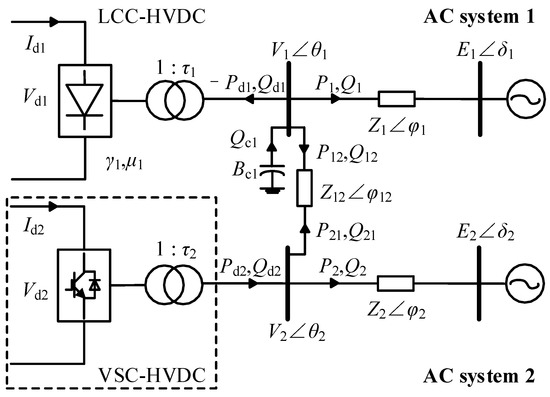
Figure 1.
Hybrid dual-infeed HVDC system model.
For the LCC-HVDC link, the quasi-steady-state DC model [12] is adopted, which can be expressed by the following algebraic equations:
For the VSC-HVDC link, it can realize flexible control of active and reactive power [19]. When the VSC converter operates in constant active power control mode, its characteristic equation can be described as:
Two kinds of control modes are considered for reactive power control. When the VSC converter operates in constant reactive power control mode, there is:
When the VSC converter operates in constant AC voltage control mode, there is:
For the AC network, the power flow equations can be described as follows:
At the converter bus, the following balance equations can be obtained:
where:
In Equations (1)–(15), Pd1, −Qd1, Pd2, Qd2 are the active power and reactive power injected into the AC system by LCC-HVDC and VSC-HVDC, respectively; Vd1, Id1 are the DC voltage and DC current of LCC-HVDC; μ1, γ1 are the commutation overlap angle and extinction angle of LCC-HVDC; τ1, Xt1 are the transformer turns ratio and leakage reactance of LCC-HVDC; Kb is the number of six-pulse bridges of LCC-HVDC; Pd2ref, Qd2ref and V2ref are the reference values of the VSC-HVDC constant active power control, constant reactive power control and constant AC voltage control, respectively; Vi θi is the converter bus voltage; Ei δi is the equivalent source voltage of the connected AC system; Pi and Qi are the active power and reactive power of the AC system i; Pij and Qij are the active power and reactive power flowing from the AC system i to j; Zi φi and Zij φij are the equivalent impedance of the AC system i and the coupling impedance between the AC system i and j, respectively; Bc1, Qc1 are the equivalent admittance and reactive power of the filters and compensators for LCC-HVDC; where i, j = 1, 2 and i ≠ j.
2.2. Model Solution
For the above-mentioned hybrid dual-infeed HVDC system, the solution of the mathematical model can be divided into two cases: rated operating condition and non-rated operating condition.
Under the rated operating condition, all variables of the AC/DC system are the nominal values, and the reactive power consumed by LCC-HVDC is completely provided by the filters and compensators connected at the converter bus. It satisfies:
where γN1, VN1, VdN1, and IdN1 are the extinction angle, AC bus voltage, DC voltage, and DC current of LCC-HVDC under the rated state, respectively.
For VSC-HVDC, its rated state has nothing to do with the control mode, and it satisfies:
where VN2, PdN2, and QdN2 are the AC bus voltage, active power, and reactive power of VSC-HVDC under the rated state, respectively. Normally, the VSC-HVDC does not deliver reactive power to the AC system under the rated state—that is, QdN2 = 0.
In addition, when the whole system is in the rated state, the active power exchange P12 between the AC system 1 and 2 is set to a certain planned value Ptie0 (usually 0). It satisfies:
If we assume that the parameters Zi φi, Zij φij and Xt1 are known and let δ1 = 0, then, according to Equations (1)–(4) and (8)–(18), the value of parameters Ei δi, τ1 and Bc1 under the rated state can be obtained by applying the Newton–Raphson method.
Under the non-rated operating condition, keeping the parameters Ei δi, τ1 and Bc1 constant, there are 21 unknown operating state variables in the whole system: μ1, γ1, Id1, Vd1, Vi, θi, Pdi, Qdi, Pi, Qi, Pij, Qij, Qc1 (i, j = 1, 2 and i ≠ j). According to Equations (1)–(15), it can be seen that the whole system contains 19 constraint equations. Therefore, only two operating state variables are independent. Select γ1 and Id1 as the independent variables of the system. Once the independent variables are determined, the remaining operating state variables will also be determined. It should be noted that when the VSC-HVDC operates in constant AC voltage control mode, the maximum allowable power limit S2max of the VSC converter should be considered. Under the premise that the connected AC bus voltage is V2ref, whether the actual reactive power Qd2act provided by VSC-HVDC exceeds its reactive power limit Q2limit should be calculated. When Qd2act exceeds the limit, its control mode is changed from constant AC voltage control to constant reactive power control, and its reactive power reference value is:
3. Power Stability Analysis of Hybrid Dual-Infeed HVDC Systems
3.1. Concept of Maximum Power Curve
According to the analysis in Section 2.2, once the selected independent variables γ1 and Id1 are determined, the remaining operating state variables will also be determined. Therefore, the active power Pd1 of LCC-HVDC can be represented by these two independent variables.
When γ1 = γ1N = γmin, the Pd1~Id1 curve is defined as the maximum power curve of LCC-HVDC [12,20]. Next, the shape of the Pd1~Id1 curve will be explained.
Substitute Equation (3) into Equation (1), and we can obtain:
where:
Therefore, the Pd1~Id1 curve approximates a downward opening parabola, as shown in Figure 2. Point N is the rated operating point, and point M is the maximum available power point of LCC-HVDC.
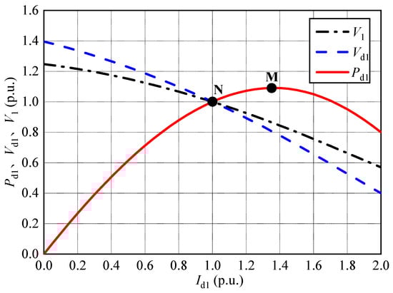
Figure 2.
Curves of V1, Vd1 and Pd1 versus Id1 of LCC-HVDC.
3.2. Power Stability Margin
The power stability of LCC-HVDC is the main factor restricting the normal and stable operation of HVDC systems [12,21]. For any operating point on the Pd1~Id1 curve, its slope is defined as the power stability index (PSI) of the HVDC system at this point [22]:
According to Figure 2, when the HVDC system operates on the left side of the maximum available power point M, Pd1 increases with the increase of Id1—that is, PSI > 0; When the system operates on the right side of point M, Pd1 decreases with the increase of Id1—that is, PSI < 0. Here, the small disturbance method can be used to test the power stability of the left and right sides of point M. For the left area of point M, it is assumed that there is a positive small disturbance ΔId1. According to the maximum power curve, the increase of Id1 will lead to the increase of Pd1. Under the action of the constant power controller of the HVDC system, the command value of Id1 will be reduced, so that the current will return to the initial point. Therefore, when PSI > 0, the HVDC system can maintain power stability. On the other hand, for the right area of point M, the existence of ΔId1 will lead to the decrease of Pd1. Under the action of the constant power controller, the command value of Id1 will be increased, so that the DC power Pd1 will further drop. The system cannot return to the initial equilibrium point. Therefore, when PSI < 0, the HVDC system is difficult to operate stably. Power stability is essentially a stability problem under small disturbances. Next, the main influencing factors of the PSI value are further analyzed.
When the inverter side of LCC-HVDC is in constant extinction angle control mode (γ1 = γ1N), according to Equations (21) and (22), Pd1 is a function of V1 and Id1. Then, we can obtain:
Equation (24) is the detailed analytical expression of PSI. For any operating point, as long as V1, Id1, and dV1/dId1 are known, the PSI value can be calculated. At the rated operating point, V1 = 1, Id1 = 1, the value of PSI is only related to dV1/dId1. The power stability of the HVDC system is related to the voltage support strength of the receiving end system. The greater the voltage support strength of the receiving end system, the smaller the decrease of V1 with the same increment of Id1, resulting in the greater value of dV1/dId1. Therefore, the value of PSI is greater, and the power stability of the HVDC system is better.
3.3. The Influence of VSC-HVDC Control Mode on the Power Stability of the System
The rated operating parameters of LCC-HVDC and the receiving end power grid parameters are given in Appendix A. The base power of the system is 1600 MW, and the base voltages at the AC side and DC side are 525 kV and 500 kV, respectively. Let PdN2 = 1.0 p.u., QdN2 = 0 p.u., VN2 = 1.0 p.u., and the other parameters remain unchanged. The maximum power curves of LCC-HVDC under different VSC-HVDC control modes are shown in Figure 3. In the figure, LCC, LCC + VSC (Q), and LCC + VSC (V), respectively, refer to three cases: no VSC-HVDC system, VSC-HVDC system with constant reactive power control mode, and VSC-HVDC system with constant AC voltage control mode. The power stability indexes of LCC-HVDC at the rated operating point under different control modes are calculated, as shown in Table 1.
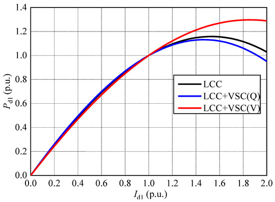
Figure 3.
Maximum power curves of LCC-HVDC under different control modes.

Table 1.
Power stability indexes of LCC-HVDC at the rated point under different control modes.
According to Figure 3 and Table 1, under different VSC-HVDC control modes, the PSI values at the rated operating point are different, and the order from high to low is: LCC + VSC (V) > LCC > LCC + VSC (Q). Compared with no VSC-HVDC, the VSC-HVDC constant reactive power control mode will deteriorate the power stability of the HVDC system at the rated operating point, while the constant voltage control mode will improve the power stability of the HVDC system.
3.4. The Influence of VSC-HVDC Transmission Power on the Power Stability of the System
In this section, the influence of VSC-HVDC transmission power on the power stability of the system is studied. Keep the AC power grid parameters unchanged. Considering the two control modes of VSC-HVDC, the maximum power curves of LCC-HVDC under different VSC-HVDC rated transmission power are shown in Figure 4.
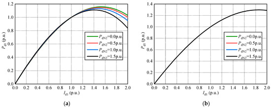
Figure 4.
Maximum power curves of LCC-HVDC under different VSC-HVDC transmission power: (a) Constant reactive power control mode; (b) constant AC voltage control mode.
According to Figure 4, when the VSC-HVDC is in constant reactive power control mode, the greater the rated transmission power PdN2 is, the worse the power stability of the system is. When the VSC-HVDC is in constant AC voltage control mode, the maximum power curves under different transmission power are coincident, which indicates that the transmission power of VSC-HVDC has almost no effect on the power stability of the system under this control mode.
4. Evaluation Criteria for the Power Stability of Hybrid Dual-Infeed HVDC Systems
4.1. Effective Short Circuit Ratio (ESCR)
For single-infeed LCC-HVDC systems, the ESCR index can be used to evaluate the power stability of HVDC systems [10,11,12]. Whether the ESCR index can still be used to quantitatively evaluate the power stability of hybrid dual-infeed HVDC systems is the focus of this paper. The ESCR is defined as:
where Sc is the three-phase short circuit capacity of the converter bus. QcN is the rated reactive power provided by the filters and compensators in the converter station, and PdN is the rated DC power of the converter station.
4.2. Study on the Effectiveness of Effective Short Circuit Ratio on the Power Stability of Hybrid Dual-Infeed HVDC Systems
The power stability margin of hybrid dual-infeed HVDC systems at the rated operating point is the most concerning issue in power grid planning and operation. Unlike the single-infeed LCC-HVDC system, the analytical expression of the critical effective short-circuit ratio cannot be derived theoretically for the hybrid dual-infeed HVDC system. Therefore, in the following analysis, the PSI~ESCR curves under different system parameters are compared to investigate whether there is a clear one-to-one correspondence between PSI and ESCR at the rated operating point. According to the analysis in Section 2.2, under the premise of clear system parameters, the maximum power curve Pd1~Id1 of LCC-HVDC can be obtained by adjusting the value of Id1, and then the PSI value at the rated operating point can be calculated. Furthermore, the relationship between PSI and ESCR can be obtained by adjusting the value of the impedance parameter Z1. The specific calculation process is shown in Figure 5, where ΔId1 and ΔZ1 denote the simulation step.
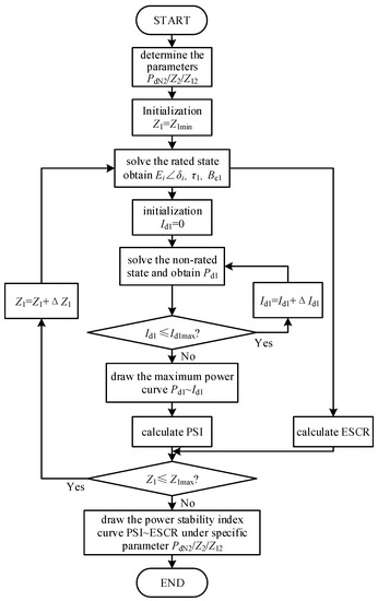
Figure 5.
Calculation process of power stability index curve PSI~ESCR.
4.2.1. Case 1: VSC-HVDC Constant Reactive Power Control Mode
According to the analysis in Section 3.4, when the VSC-HVDC is in constant reactive power control mode, the power stability of the system is different under different rated transmission power of VSC-HVDC. From Equations (5) and (6), it can be seen that the connection of VSC-HVDC is equivalent to that of a constant power load at the converter bus. In the following, the relationship between PSI and ESCR is investigated under different system parameters.
- The influence of parameter PdN2
Change the rated transmission power of VSC-HVDC, and investigate the relationship between PSI and ESCR under different PdN2. Figure 6 shows the curves of PSI versus ESCR when PdN2 is 0 p.u., 0.5 p.u., 1.0 p.u. and 1.5 p.u., respectively. It can be seen that: under the same PdN2, the greater the ESCR is, the greater the PSI is, and the better the power stability of the system is. The obtained ESCR when PSI = 0 is defined as the critical effective short circuit ratio (CESCR) of the system, which is the minimum requirement for the normal and stable operation of the HVDC system. Taking PdN2 = 0.5 p.u. as an example, the CESCR of the system is 1.64. It means that only when ESCR > 1.64 can the HVDC system operate normally and stably. Comparing the four curves in Figure 6, we can conclude that the value of CESCR increases with the increase of PdN2. When PdN2 increases from 0 p.u. to 1.5 p.u., the variable range of CESCR is 1.52~2.0.
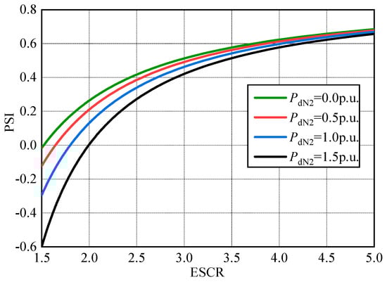
Figure 6.
Curves of PSI versus ESCR for different PdN2 under VSC-HVDC constant reactive power control mode.
- 2.
- The influence of parameter Z2
Change the equivalent impedance of the AC system corresponding to VSC-HVDC, and investigate the relationship between PSI and ESCR under different Z2. Figure 7 shows the curves of PSI versus ESCR when PdN2 = 0.5 p.u., Z2 is 0.2 p.u., 0.35 p.u., 0.55 p.u. and 0.75 p.u., respectively. It can be seen that under the same Z2, PSI increases with the increase of ESCR. The smaller Z2 is, the smaller the CESCR of the system is. The variable range of CESCR is 1.59~1.75.
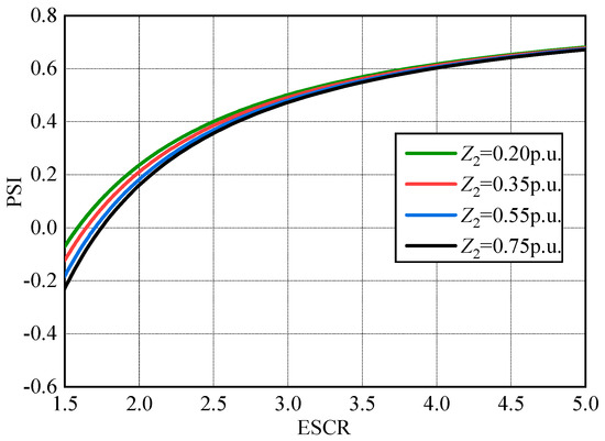
Figure 7.
Curves of PSI versus ESCR for different Z2 under VSC-HVDC constant reactive power control mode.
- 3.
- The influence of parameter Z12
Change the coupling impedance between AC system 1 and 2 and investigate the relationship between PSI and ESCR under different Z12. Figure 8 shows the curves of PSI versus ESCR when PdN2 = 0.5 p.u., Z12 is 0.15 p.u., 0.30 p.u., 0.50 p.u. and 0.70 p.u., respectively. It can be seen that under the same Z12, PSI increases with the increase of ESCR. The greater Z12 is, the smaller the CESCR of the system is. The variable range of CESCR is 1.57~1.72.
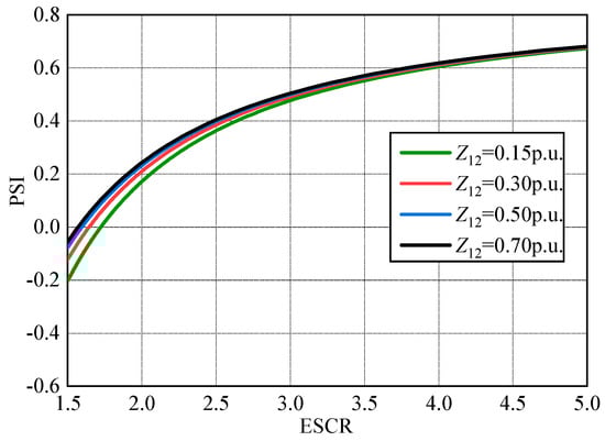
Figure 8.
Curves of PSI versus ESCR for different Z12 under VSC-HVDC constant reactive power control mode.
According to Figure 6, Figure 7 and Figure 8, when the VSC-HVDC is in constant reactive power control mode, the relationship between PSI and ESCR is summarized as follows:
- (1)
- ESCR has a clear indicative function on the power stability of the hybrid dual-infeed HVDC system. The greater the ESCR is, the better the power stability of the system is.
- (2)
- The value of CESCR is affected by system parameters. The greater PdN2 is, the greater the CESCR is; the greater Z2 is, the greater the CESCR is; the greater Z12 is, the smaller the CESCR is.
- (3)
- The greater the ESCR is, the smaller the influence of system parameters on the indicative function of ESCR is. Among the above three system parameters, PdN2 has the greatest influence on the quantitative relationship between PSI and ESCR, and the variable range of CESCR is 1.52~2.0.
4.2.2. Case 2: VSC-HVDC Constant AC Voltage Control Mode
According to the analysis in Section 3.4, when the VSC-HVDC is in constant AC voltage control mode, the power stability of the system is independent of the rated transmission power of VSC-HVDC. For the AC system, the VSC converter station is equivalent to a generator with reactive capacity constraints. The connection of VSC-HVDC shortens the electrical distance from the converter bus of LCC-HVDC to the constant voltage point. Therefore, the generator characteristics of VSC-HVDC should be considered when calculating the ESCR. In this case, the power stability of the system is mainly related to the parameter Z12. In the following, the relationship between PSI and ESCR is investigated under different Z12.
Figure 9 shows the curves of PSI versus ESCR when PdN2 = 0.5 p.u., Z12 is 0.6 p.u., 0.8 p.u., 1.0 p.u. and 1.2 p.u., respectively. It can be seen that under the same Z12, PSI increases with the increase of ESCR. The value of CESCR is slightly affected by the parameter Z12. The variable range of CESCR is 1.56~1.65.
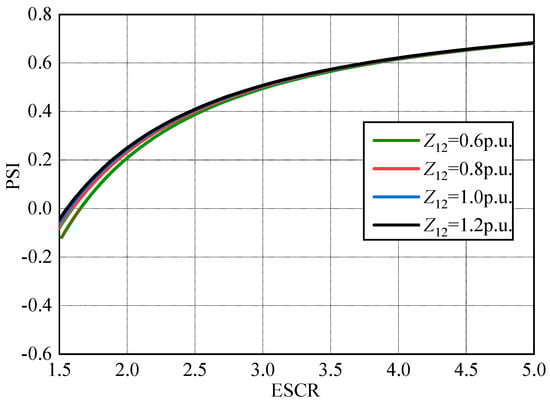
Figure 9.
Curves of PSI versus ESCR for different Z12 under VSC-HVDC constant AC voltage control mode.
4.3. Evaluation Criteria for the Stable Operation of Hybrid Dual-Infeed HVDC Systems
The evaluation criteria of power stability for the hybrid dual-infeed HVDC system can be divided into two cases: constant AC voltage control mode and constant reactive power control mode. The expert in [22] proposed that when PSI > 0.4, the HVDC system has a high stability margin.
Based on the above analysis, it can be seen that if the VSC-HVDC is in constant AC voltage control mode, the variable range of CESCR is 1.56~1.65, and when PSI = 0.4, the variable range of ESCR is 2.48~2.63. Therefore, the evaluation criteria of the single-infeed LCC-HVDC system can still be used.
If the VSC-HVDC is in constant reactive power control mode, the variable range of CESCR is 1.52~2.0, and when PSI = 0.4, the variable range of ESCR is 2.45~2.9. In order to ensure a sufficient stability margin, the evaluation criteria of power stability can be divided as follows:
- (1)
- When ESCR < 2.0, the HVDC system is difficult to operate stably.
- (2)
- When 2.0 < ESCR < 3.0, the HVDC system can operate stably, but the stability margin is low.
- (3)
- When ESCR > 3.0, the HVDC system can operate stably with high stability margin.
5. Simulation Verification
Generally, the electromechanical transient simulation is preferred to study the stability of actual AC/DC power systems [23,24]. As the most widely used tool for power system electromechanical transient simulations, PSS/E can meet various analysis needs of users. The performance of the HVDC model in PSS/E has been confirmed in [25].
Therefore, in order to verify the effectiveness of the above calculation results, based on PSS/E, this paper analyzes the power stability of the hybrid dual-infeed HVDC system shown in Figure 1. LCC-HVDC adopts the CDC6 quasi-steady-state model [26]. The rectifier side is in constant current control mode, and the inverter side is in constant extinction angle control mode. VSC-HVDC is replaced by a constant power load model and a generator model under constant reactive power control mode and constant AC voltage control mode, respectively. By applying a small current increment ΔId1 (about 0.01 p.u.) to Id1, the PSI value at the rated operating point can be obtained. Under different receiving-end system strengths, the calculation results of the two methods are compared, as shown in Table 2.
Table 2.
LCC-HVDC power stability index under different receiving-end system strengths.
According to Table 2, with the increase of ESCR, the PSI value increases, and the power stability of the HVDC system is better. Taking the VSC-HVDC constant reactive power control mode as an example, when ESCR = 2.18, the PSI value is only 0.12, and the power stability of the HVDC system is very weak; only when ESCR > 3.02 can the HVDC system operate stably with a high stability margin. In addition, the PSI calculation results under the two methods are basically consistent. Therefore, the aforementioned evaluation criteria are valid.
6. Conclusions
Based on the concepts of the maximum power curve and the power stability index, this paper has analyzed the influence of VSC-HVDC on the power stability of the hybrid dual-infeed HVDC system and further studied the quantitative relationship between the power stability and the effective short circuit ratio under different system parameters. The main conclusions are summarized as follows:
- (1)
- For the hybrid dual-infeed HVDC system, the strengthening effect of VSC-HVDC on the system is related to its control mode. When the VSC converter operates in constant AC voltage control mode, the system can be strengthened, while when it operates in constant reactive power control mode, the power stability of the system may be weakened.
- (2)
- If the VSC converter operates in constant AC voltage control mode, the transmission power of VSC-HVDC has almost no effect on the power stability of the system. If the VSC converter operates in constant reactive power control mode, the transmission power of VSC-HVDC has a significant effect on the stability of the system. The greater the transmission power is, the worse the power stability of the system is.
- (3)
- There is a relatively clear quantitative relationship between the power stability and the effective short circuit ratio in the hybrid dual-infeed HVDC system. The greater the ESCR is, the better the power stability of the system is. The ESCR index can still be used to evaluate the power stability of the hybrid dual-infeed HVDC system.
- (4)
- If the VSC-HVDC is in constant AC voltage control mode, the CESCR is slightly affected by system parameters, and its variable range is 1.56~1.65. Therefore, the power stability evaluation criteria of the single-infeed LCC-HVDC system can still be used in the hybrid dual-infeed HVDC system. It can be considered that the HVDC system cannot operate stably when ESCR is less than 1.5.
- (5)
- If the VSC-HVDC is in constant reactive power control mode, the CESCR is mainly affected by the transmission power of VSC-HVDC, and its variable range is 1.52~2.0. In order to ensure a sufficient stability margin, it can be considered that the HVDC system cannot operate stably when ESCR is less than 2.0 and can operate stably with a high power stability margin when ESCR is greater than 3.0.
These conclusions can be used to guide the planning and operation of the hybrid dual-infeed HVDC system. The proposed evaluation criteria of power stability can be used for the location determination of the HVDC system in the hybrid dual-infeed situation. It should be noted that although the ESCR index can still be used to evaluate the power stability of the HVDC system in the hybrid dual-infeed situation, its calculation and evaluation criteria need to consider two control modes, which will bring inconvenience to the analysis of the actual power system to a certain extent. In future works, new indexes of power stability for hybrid dual-infeed HVDC systems should be studied.
Author Contributions
Investigation, writing: X.W.; supervision: Z.X. and Z.Z. All authors have read and agreed to the published version of the manuscript.
Funding
This research was funded by the Science and Technology Project of State Grid Corporation of China ‘Research on Analysis Method and Structure Optimization Technology of Receiving-End Power Grid with Large Capacity Conventional/Flexible DC Transmission System Hybrid Infeed’, grant number 521532190003.
Institutional Review Board Statement
Not applicable.
Informed Consent Statement
Not applicable.
Data Availability Statement
The data presented in this study are available in the article.
Conflicts of Interest
The authors declare no conflict of interest.
Appendix A
The rated operating parameters of LCC-HVDC and the receiving end power grid parameters are given in Table A1 and Table A2, respectively.
Table A1.
Rated operating parameters of LCC-HVDC.
Table A1.
Rated operating parameters of LCC-HVDC.
| Item | Rated Value |
|---|---|
| Number of six-pulse bridges | 2 |
| Rated DC voltage (kV) | 500 |
| Rated DC current (kA) | 3.2 |
| Rated extinction angle (°) | 18 |
| Rated L-L RMS voltage of the AC system (kV) | 525 |
| Rated capacity of the single transformer (MVA) | 880 |
| Leakage reactance of transformer (%) | 18 |
Table A2.
Parameters of the receiving-end power grid.
Table A2.
Parameters of the receiving-end power grid.
| Impedance Parameter | Amplitude (p.u.) | Phase Angle (Rad) |
|---|---|---|
| Z1φ1 | 0.35 | π/2 |
| Z2φ2 | 0.35 | π/2 |
| Z12φ12 | 0.3 | π/2 |
References
- Prabna, K. Power System Stability and Control; McGraw-Hill: New York, NY, USA, 1994. [Google Scholar]
- Bahrman, M.P.; Johnson, B.K. The ABCs of HVDC Transmission Technologies. IEEE Power Energy Mag. 2007, 5, 32–44. [Google Scholar] [CrossRef]
- Huang, D.; Shu, Y.; Ruan, J.; Hu, Y. Ultra High Voltage Transmission in China: Developments, Current Status and Future Prospects. Proc. IEEE 2009, 97, 555–583. [Google Scholar] [CrossRef]
- Lu, S.; Xu, Z.; Xiao, L.; Jiang, W.; Bie, X. Evaluation and Enhancement of Control Strategies for VSC Stations Under Weak Grid Strengths. IEEE Trans. Power Syst. 2018, 33, 1836–1847. [Google Scholar] [CrossRef]
- Zhang, Z.; Lee, J.; Jang, G. Improved Control Strategy of MMC–HVDC to Improve Frequency Support of AC System. Appl. Sci. 2020, 10, 7282. [Google Scholar] [CrossRef]
- Jiang, B.; Wang, Z. The Key Technologies of VSC-MTDC and Its Application in China. Renew. Sustain. Energy Rev. 2016, 62, 297–304. [Google Scholar]
- Hu, K.; Peng, J.; Wang, Z. Research on the Interaction between Luxi Back-to-Back and Yongfu HVDe. In Proceedings of the 2018 China International Conference on Electricity Distribution (CICED), Tianjin, China, 17–19 September 2018; pp. 1127–1131. [Google Scholar]
- Zhu, Y.; Guo, Q.; Li, C.; Chang, D.; Chen, D.; Zhu, Y. Research on Power Modulation Strategy for MMC-HVDC and LCC-HVDC in Parallel HVDC System. In Proceedings of the 2019 IEEE 3rd Conference on Energy Internet and Energy System Integration (EI2), Changsha, China, 8–10 November 2019; pp. 1456–1461. [Google Scholar]
- IEEE Guide for Planning DC Links Terminating at AC Locations Having Low Short-Circuit Capacities. In IEEE Standard 1204–1997; IEEE: Manhattan, NY, USA, 1997.
- Aik, D.L.H.; Andersson, G. Power Stability Analysis of Multi-Infeed HVDC Systems. IEEE Trans. Power Deliv. 1998, 13, 923–931. [Google Scholar] [CrossRef]
- Zhou, B.; Rao, H.; Wu, W.; Wang, T.; Hong, C.; Huang, D.; Yao, W.; Su, X.; Mao, T. Principle and Application of Asynchronous Operation of China Southern Power Grid. IEEE J. Emerg. Sel. Top. Power Electron. 2018, 6, 1032–1040. [Google Scholar] [CrossRef]
- Xu, Z. Dynamic Behavior Analysis of AC-DC Power System; China Machine Press: Beijing, China, 2004. [Google Scholar]
- Zhang, X.; Chen, C. Maximum Available Power of Multi-infeed Hvdc System Analysed by Sensitivity Method. IET Gener. Transm. Distrib. 2014, 8, 473–479. [Google Scholar] [CrossRef]
- CIGRE Working Group B4.41. Systems with Multiple DC Infeed; CIGRE: Paris, France, 2008. [Google Scholar]
- Chen, X.; Guan, L. Research on Limitation of the Multi-Infeed Short Circuit Ratio. In Proceedings of the 2016 IEEE PES Asia-Pacific Power and Energy Engineering Conference (APPEEC), Xi’an, China, 25–28 October 2016; IEEE: Manhattan, NY, USA; pp. 712–715. [Google Scholar]
- Xia, C.; Wang, Z.; Zhou, B.; Nie, J.; Hong, C. Effects of VSC-HVDC on Receiving-end System Strength of LCC-HVDC. Power Syst. Technol. 2019, 43, 2031–2038. [Google Scholar]
- Guo, C.; Zhang, Y.; Gole, A.M.; Zhao, C. Analysis of Dual-Infeed HVDC with LCC–HVDC and VSC–HVDC. IEEE Trans. Power Deliv. 2012, 27, 1529–1537. [Google Scholar] [CrossRef]
- Tian, B.; Yuan, Z.; Yu, X.; Rao, H.; Zhou, B.; Li, H.; Nie, J. Influence of VSC-HVDC on the Strength of LCC-HVDC Receiving Power Grid in Hybrid Dual-infeed HVDC System. Proc. CSEE 2019, 39, 3443–3454. [Google Scholar]
- Liu, Y.; Chen, Z. Short Circuit Ratio Analysis of Multi-Infeed HVDC System with a VSC-HVDC Link. In Proceedings of the IECON 2011—37th Annual Conference of the IEEE Industrial Electronics Society, Melbourne, Australia, 7–10 November 2011; pp. 949–954. [Google Scholar]
- Xia, C.; Li, X.; Li, S.; Zhou, B. Definition and Analysis of Receiving System Voltage Support Strength Factor. IEEE Access 2019, 7, 134206–134214. [Google Scholar] [CrossRef]
- Ni, X.; Gole, A.M.; Zhao, C.; Guo, C. An Improved Measure of AC System Strength for Performance Analysis of Multi-Infeed HVdc Systems Including VSC and LCC Converters. IEEE Trans. Power Deliv. 2018, 33, 169–178. [Google Scholar] [CrossRef]
- Huang, H. AC/DC Power System Transient Stability Analysis and Control. Ph.D. Dissertation, Zhejiang University, Hangzhou, China, 2014. [Google Scholar]
- Liu, S.; Xu, Z.; Hua, W.; Tang, G.; Xue, Y. Electromechanical Transient Modeling of Modular Multilevel Converter Based Multi-Terminal HVDC Systems. IEEE Trans. Power Syst. 2014, 29, 72–83. [Google Scholar] [CrossRef]
- Xiao, L.; Li, Y.; Xiao, H.; Zhang, Z.; Xu, Z. Electromechanical Transient Modeling of Line Commutated Converter-Modular Multilevel Converter-Based Hybrid Multi-Terminal High Voltage Direct Current Transmission Systems. Energies 2018, 11, 2102. [Google Scholar] [CrossRef] [Green Version]
- Kwon, D.-H.; Moon, H.-J.; Kim, R.-G.; Kim, C.-G.; Moon, S.-I. Modeling of CIGRE Benchmark HVDC System Using PSS/E Compared with PSCAD. In Proceedings of the 2015 5th International Youth Conference on Energy (IYCE), Pisa, Italy, 27–30 May 2015; IEEE: Manhattan, NY, USA; pp. 1–8. [Google Scholar]
- Wu, X.; Xu, Z.; Yang, J. Simulation Research on Switching Process of Reactive Power Equipment in DC Converter Station. In Proceedings of the 2019 IEEE Innovative Smart Grid Technologies—Asia (ISGT Asia), Chengdu, China, 21–24 May 2019; pp. 2308–2313. [Google Scholar]
Publisher’s Note: MDPI stays neutral with regard to jurisdictional claims in published maps and institutional affiliations. |
© 2021 by the authors. Licensee MDPI, Basel, Switzerland. This article is an open access article distributed under the terms and conditions of the Creative Commons Attribution (CC BY) license (https://creativecommons.org/licenses/by/4.0/).