Article

Mechanics of Screw Joints Solved as Beams Placed in a Tangential Elastic Foundation

1
Faculty of Mechanical Engineering, VSB-Technical University of Ostrava, 17. Listopadu 15/2172, 708 00 Ostrava-Poruba, Czech Republic
2
Faculty of Medicine, University of Ostrava, Syllabova 19, 703 00 Ostrava-Vítkovice, Czech Republic
3
Trauma Center, University Hospital Ostrava, 17. listopadu 1790, 708 52 Ostrava-Poruba, Czech Republic
4
Medin, a.s, Vlachovicka 619, 592 31 Nové Město na Moravě, Czech Republic
5
Center of Advanced Innovation Technologies, VSB-Technical University of Ostrava, 17. Listopadu 15/2172, 708 00 Ostrava-Poruba, Czech Republic
6
V-NASS, a.s., Halasova 2938/1a, 703 00 Ostrava-Vítkovice, Czech Republic
7
Faculty of Mechanical Engineering, Slovak University of Technology in Bratislava, Námestie Slobody 17, 812 31 Bratislava 1, Slovakia
8
Faculty of Safety Engineering, VSB-Technical University of Ostrava, Lumírova 630/13, 700 30 Ostrava-Výškovice, Czech Republic
*
Author to whom correspondence should be addressed.
Appl. Sci. 2021, 11(12), 5616; https://doi.org/10.3390/app11125616
Submission received: 15 January 2021 / Revised: 10 February 2021 / Accepted: 2 March 2021 / Published: 17 June 2021

Abstract

:
This article deals with a new original analytical solution of deformation, force and stress states in wood screw joints up to the limit values of pulling out/breaking the screw. The screws are under tension. The wood-to-screw interaction is effectively simplified by introducing several physical model variants using a tangential elastic non-linear foundation. The experimental verification of the proposed models using pull-out tests (i.e., pulling out screws from dry spruce wood in laboratory conditions) confirms the correctness of the proposed models of the elastic linear/non-linear foundation. The validity of the model is also analytically and experimentally verified in the biomechanical model of pulling out screws from the femur of a bovine/human cadaver, which confirms and expands the validity of newly designed screw joint models outside the timber structure area.

1. Introduction

Screw joints of various types and designs are very common in general technical practice. These are, e.g., removable/permanent joints of wood or other materials (wooden structures, plastics, furniture, construction, automotive industry, etc.), dowel joints, thread-forming/self-tapping/self-drilling screws, foundation screws, ground screws, shrink rings, etc. (see Figure 1a–c and references [1,2,3,4,5,6,7,8,9]).
Screw joints are actually a variation of a bolted joint (see [5,10,11]).
Important applications of screws are also found in surgery and in the treatment of complicated fractures and deformities of humans/animals in traumatology/orthopaedics (external and internal fixations in osteosyntheses, etc.) (see Figure 1c and, for example, references [12,13,14,15,16,17,18,19,20,21]).
It is also surprising that screw joints even occur naturally in some biological tissues, e.g., coxa–trochanteral joints on the legs of the weevil Trigonopterus oblongus. The hips of weevils do not consist of the usual hinges, but of “unknown” joints based on a screw-and-nut system. This “unusual” biological screw thread is about half a millimeter in size (see references [22,23]).
Pull-out tests of screw joints are carried out mostly in orthopaedics/traumatology applications (see [16,24,25,26,27,28]). Orthopaedic/traumatology surgery often involves the use of bone screws to stabilize fractures via fixation techniques. Measured or calculated pull-out strength is commonly used to measure screw fixation strength and for the reliability assessment of screw fixation. However, “similar” applications are found in wooden structures (see [1,4]).
For the above reasons, it is advisable to deal with the screw joint mechanics. Therefore, this article deals with new and original material models of screw joints with a focus on the interaction between the screw and the material, including the evaluation of limit states. The purpose is to find the characteristics of a tangential elastic foundation that should simplify the solved task of mechanics.
Hence, theory, the derivation of analytical linear/non-linear solutions and first experiments are exposed and evaluated.
Unlike common, simplified orientation design procedures (see [1,2,3,5,6,11] and others) and calculations using the finite element method (FEM) (see [7,10,12,16,29,30] and others), a new approach to solving the problems of screw joints is proposed, applied and experimentally verified in this article. This new approach is based on the application of the proposed tangential elastic foundation as a sufficiently accurate and effective solution to the interaction between the screw and the material to be joined.
The results and procedures are valid for the axial tensile stress of the screw joints in the elastic and elasto-plastic areas, including the limit states of pulling the screw out of the material or the screw breakage.
Depending on the technical need and severity of the problem, it is possible to choose the proposed shape of the linear/non-linear model, including its analytical solution. Thus, in some cases, the use of new tangential foundation models eliminates the need for sophisticated/time-consuming FEM modeling, and it also offers various simplifications and acceleration of the calculation, or a rapid probability stochastic approach to the solution, for example, using the Monte Carlo method, SBRA method and others (see, e.g., [6,12,29,31,32,33]).
These may lead to improving the production of screws (i.e., machining and 3D printing technologies, material properties, etc.) (for example, see [20,34,35,36,37,38,39,40]).
Therefore, there is an alternative simplification of the calculation of the tangential elastic foundation applications, which is the subject of our article. Verification of the models of the screw and joint material interaction was performed on steel and titanium screws of various types placed not only in dry spruce wood but also in a bovine/human femur with a targeted future application in biomechanics in the field of implant attachment research for the treatment of complicated fractures in traumatology/orthopaedics. The criterion for evaluating the correctness of new models is the degree of consensus of the analytical solution with the pull-out test (i.e., experiments in the laboratory at VSB—Technical University of Ostrava, Faculty of Mechanical Engineering, Department of Applied Mechanics).
In some cases, it is generally accepted that the interaction (i.e., mechanical contact) between the body and the continuum can be most easily replaced by an elastic foundation. The basic principle and thus the known fact is the linear or non-linear dependence between the foundation reaction and the deformation of the foundation.
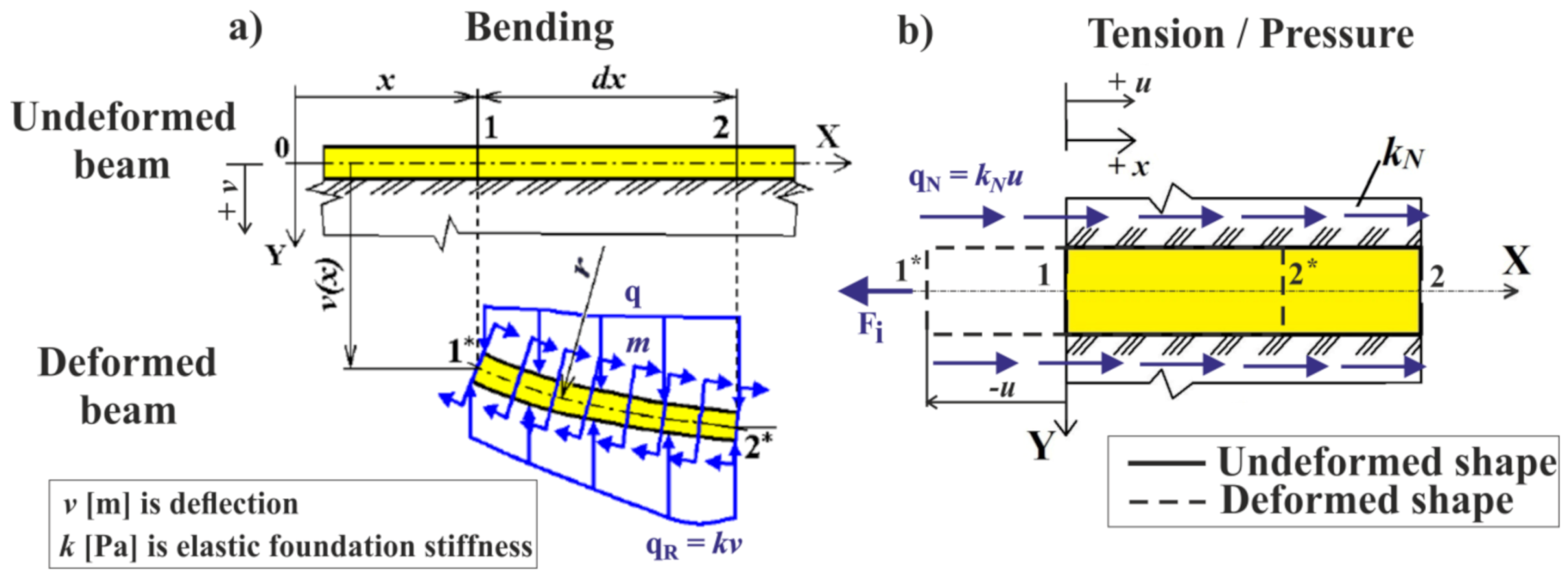
Usually, the elastic foundation is used for bending ([9,15,29,30,32,41]) (see Figure 2a), but here it is newly, unconventionally and originally used for the task of tension or pressure load (the so-called tangential elastic foundation) (see Figure 2b and different approaches presented in [42]).
In the following text, attention is focused only on the tangential elastic foundation (i.e., new type), with a more general non-linear model being considered.

2. The Tangential (Tensile) Elastic Foundation

In the case of a screw connection, it is assumed that the screw can be replaced by a beam and also that the screw is placed in the tangential elastic foundation over the length and circumference of the contact between the thread and the connected material. The screw (beam) is subjected to tension/pressure in this task.
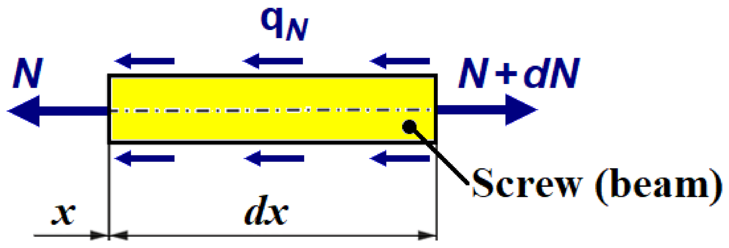
The proposed new model of elastic foundation assumes that the continuous tangent reaction in the foundation   q N = q N x ,   u ,   [Nm−1] is directly proportional to the axial displacement of the center line u = u x [m]. From equilibrium on the infinitesimal length section d x [m], the equation of equilibrium in the axial direction can be derived (see Figure 3).
N + q N d x N + d N = 0   ,   i . e . , d N d x = q N
Assuming small deformations in the screw (beam) and possible small/large deformations in the fasteners (e.g., thread tear, etc.), the relative deformation   ε [1] in tension/compression of the beam section is calculated as
ε = d u d x = N E A , ,   i . e . , d 2 u d x 2 = 1 E A d N d x ,
where A [m2] is the cross-section area of the beam (screw) and E [Pa] is the elastic modulus of the beam (screw). The relationship (2) is linear, however, the foundation and its deformation can generally be non-linear, which is a significant factor of the tangential elastic foundation.
By substituting Equations (1) to (2), the relationship for the second order homogeneous differential equation is obtained
d 2 u d x 2 = q N EA ,
which is generally non-linear.
If q N = 0 (i.e., the beam is not placed in the tangential foundation), it is a common simple tension/pressure task.
It is clear from the measurements that the dependence F = f u B and the reaction force of the tangential foundation q N are non-linear. However, despite this fact, the differential Equations (1) to (3) can be solved in an analytical way, which is advantageous and fast, since the use of numerical methods, such as the finite element method, is no longer necessary. The solution procedure is based on the best possible and most practical approximation of the experiment and is as follows.
It is assumed that q N = f u , or N = f u , as indicated by the results of the experiment. Appropriate adjustment is introduced:
d N d x = d u d u d N d x = d u d x d N d u = N E A d N d u ,
where Equation (2) is applied.
Equation (1) can be adjusted to the following form:
N d N d u = E A   q N ,
which is a separable first order differential equation. This equation is generally non-linear but can be directly solved by integration, as will be shown below. Thus, the advantage is a reduction in the order of the differential equation (i.e., reduction in the degree of derivation), which is apparent from the comparison of Equations (5) and (3).

3. Material and Methods

To solve the problem of pulling screws out of fasteners (see the previous text) it is advisable:
  • To prepare test samples for woodwork screw joints in the laboratory.
  • To determine experimentally the dependence of pulling force F = N = f u ,   in the laboratory (i.e., the pull-out test).
  • To determine the appropriate shapes of the reaction force q N (i.e., to design a physical model of the tangential foundation) based on the evaluation of the experiment (laboratory measurements, regression methods, etc.).
  • To solve differential Equation (3) based on the knowledge of the reaction force q N , i.e., to acquire the axial displacement u .
  • To compare the obtained results with experiments and to evaluate proposed models of the tangential foundation, including the correctness of theory and use.
  • To check dependencies on other materials such as bone (i.e., “similar” applications in biomechanics, traumatology and orthopaedics).
  • To conduct a discussion, draw conclusions and suggest future possible applications and other possible solutions.
The screws examined in this publication are made of two types of material, namely 1.4441 stainless steel (AISI 316L) and Ti6Al4V titanium alloy. The basic mechanical properties of these materials are given in Table 1 (see references [36,37,40]). Hence, screws are considered to be isotropic, homogeneous materials and biocompatible from a human perspective.
The screws are made using either a conventional machining method or metal powder 3D printing technology where machining is the finishing process (see [34,35,37,38,39]). However, the screw production technology is not dealt with in this article because the main objective is to verify the material models of the tangential elastic foundation. Since the screws are stiffer than wood (i.e., the screws have a greater modulus of elasticity than wood), the screw production technology does not have a significant impact on the results of the pull-out tests (see [13,24,37]).
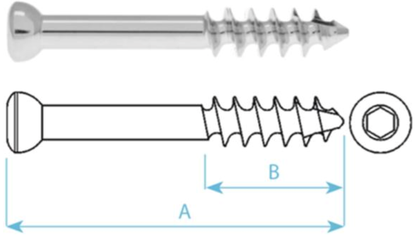
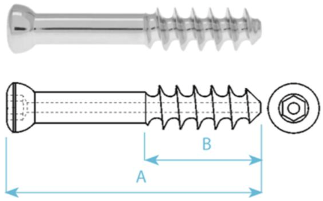
Two types of screws, HB 6.5 (full cross-section) and HB 7 (cannulated cross-section, i.e., hollow cross-section profile), are used for both computational and experimental measurements. Both screws have thread length L 2 = 0.09 m. The manufacturer of these screws is the Czech company MEDIN a.s. For more details, see Table 2 and the web page of MEDIN a.s. [20].
Thus, the tangential foundation simply replaces the effect of wood-screwed parts (i.e., simplifies mechanical contact), and this has a major impact on the practicality of the entire proposed model. Then, assuming that the functional dependency of q N is correctly determined, the model can be used for generally anisotropic and non-homogeneous and dry or moist materials, which is undoubtedly the case for wood. Therefore, the tangential foundation offers the possibility of significant and highly effective simplification in conventional timber structure calculations.
Wood is hygroscopic but “dry” wood of Picea abies was chosen for the first verification.

4. Experiment (Pull-Out Test for Screws) and Its Evaluation

The characteristics of the tangential elastic foundation (screw/wood interaction) are influenced by many factors, such as material properties, composition, age, external environment, moisture, wood degradation or biodegradation processes, etc., which affect the results of experiments.
The experiments have the possibility to verify the proposed theory of tangential elastic foundation and to verify the models of screw/wood interaction and to provide other valuable information.
Pull-out tests for screws in wooden parts were carried out on the universal testing machine TESTOMETRIC M500–50CT (laboratories of the Department of Applied Mechanics, Faculty of Mechanical Engineering, VSB—Technical University of Ostrava). TESTOMETRIC M500–50CT is a fully digital testing system with high-precision control and accuracy and high-speed data collection systems. It includes automated computer control of test methods, giving simplicity of operation. For more information, see [43].
The screws were attached in a special preparation and the pulling speed was 0.01 m/min.
For the solution, long threads (i.e., long thread areas of the contact between the thread and fasteners) were chosen, which leads to more interesting, more sophisticated research with more general use.
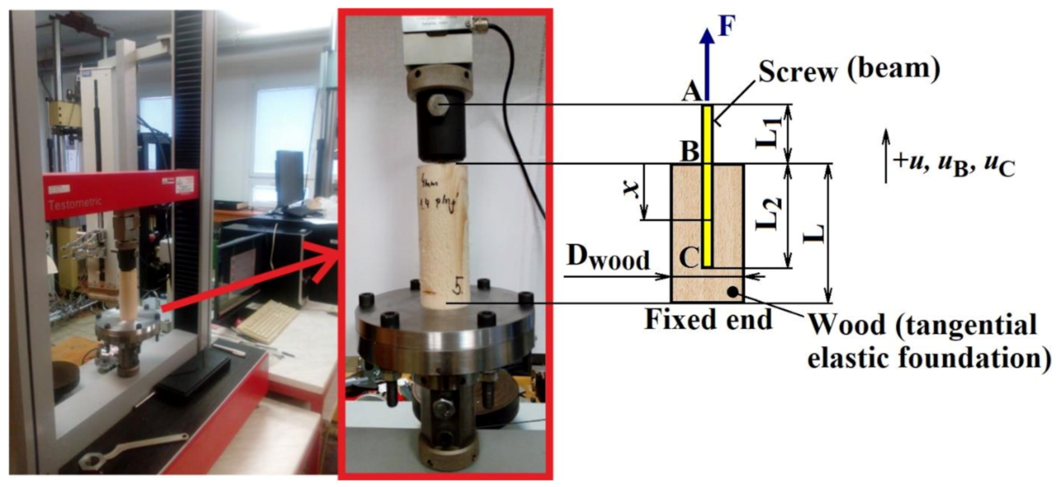
All screws were manually screwed into the pre-drilled wooden cylinder (diameter   D wood = 0.05 m, length L = 0.14 m) within the thread length, i.e., to a depth of L 2 = 0.09 m with shank length   L 1 = 0.025 m (see Figure 4).
Conventional dry spruce wood (Picea abies) of standard quality (i.e., moisture about 10%) purchased at a supermarket was used.
HB 6.5 and HB 7 screws were screwed into the wood in the grain/radial plane and in a direction perpendicular to the transversal plane (see Figure 4).
Place A in Figure 6 indicates the point where the screw in the test machine is attached in the holding device. The screw displacement u A [m] is measured at this point.
Place B in Figure 4 indicates the point where the shank ends and the thread begins. The displacement at B is, according to the general mechanics relations,   u B = u A   FL 1 E A [m] and F [N] is the measured tensile force.
“Fixed end” in Figure 4 indicates a combination of a glued joint and four small screw joints.
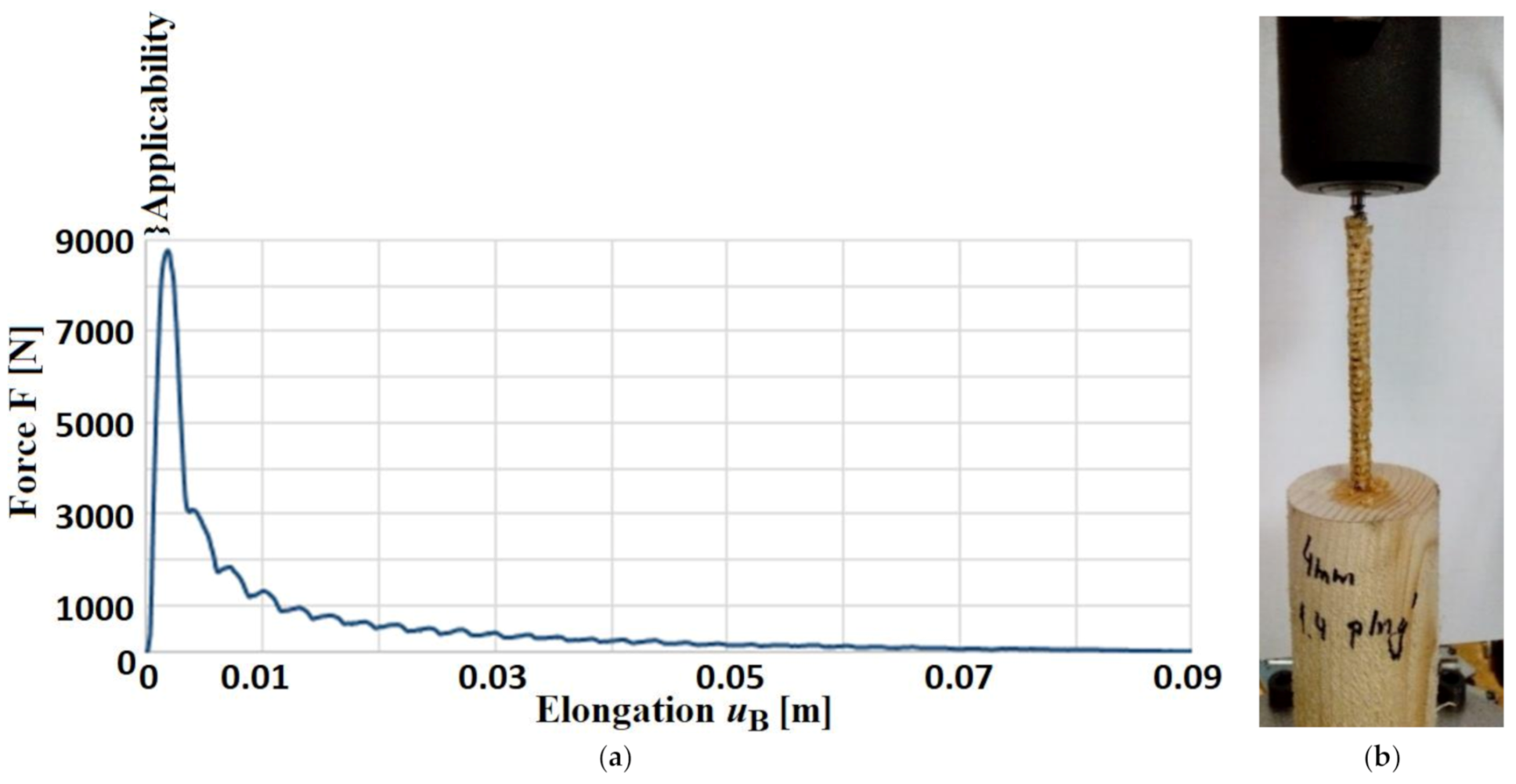
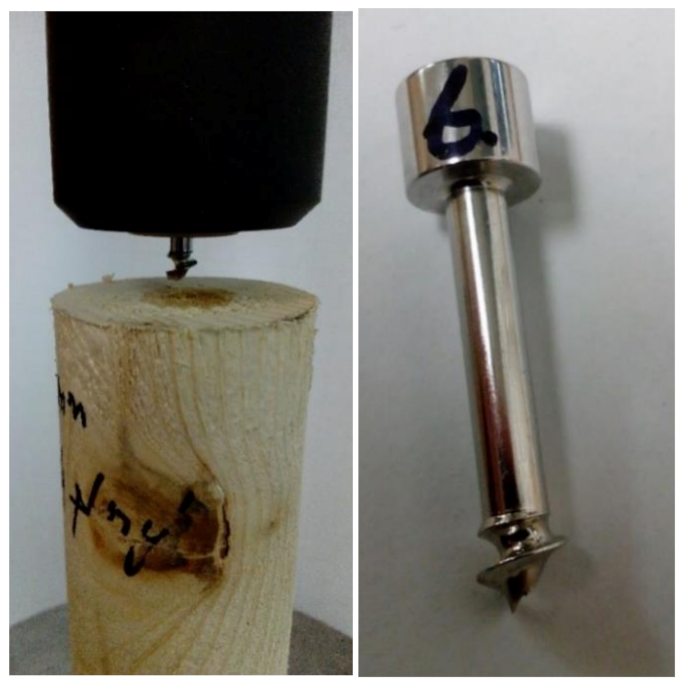
An example of the course of the experiment (i.e., the dependence   F = f u B ) and the termination of the experiment (pulling out the screw from the wood) is shown in Figure 5. It is obvious that the course of the experiment variables determines the boundary conditions for differential Equations (1) and (3).
The dependencies F = f u B , such as those presented in Figure 5, are similar to the results presented in references [16,24,25,26,27].
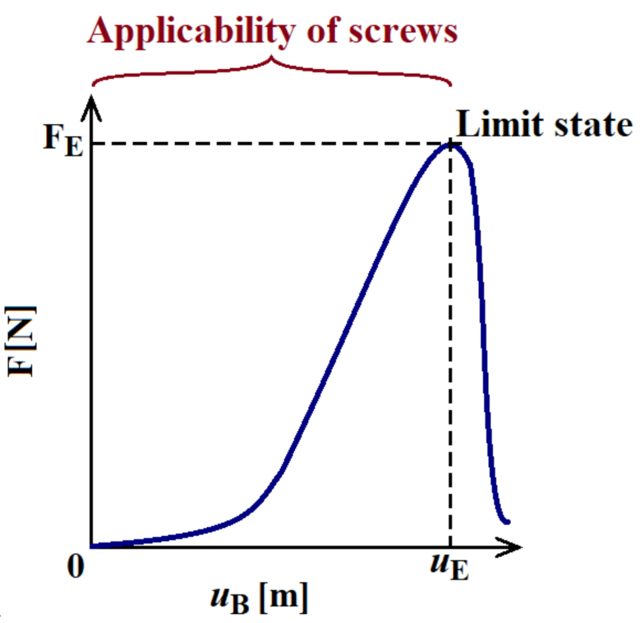
A continuous tangential reaction of the elastic foundation q N is searched only on the interval to the extreme u B   0 ; u E   and   F = N 0 ; F E , i.e., from the beginning of loading to the pulling out/breaking of the screw (see Figure 5 and Figure 6), where the displacement u E [m] and force F E [N] are values obtained from the experiment at the maximum measured tensile force F E (i.e., at the limit state). The other part of the dependence of the force on the displacement u B > u E is not examined because the entire screw is displaced and the joint is already destroyed (i.e., the limit failure state has been reached).
Hence, 13 successful measurements of pull-out tests for screws in the wood were performed (see Table 3). Most of the measurements ended with the screw pulling out (stripping thread) but some of them also ended with a screw breakage. For more details, see Figure 5b and Figure 7.
The variability of the results of measured variables F E , u E   given in Table 3 is therefore primarily due to a combination of material properties of dry spruce wood, screw materials, type of screws and pre-drilling and screwing operations. The aim was to have “diverse” results for more general verification options for the designed tangential elastic foundation models. According to the medical point of view, the variability of pre-drilled hole diameters (0.0032 to 0.0055 m) was chosen (i.e., connection to the future pull-out tests of bone joints in bovine and human femurs).
It is clear from the nature of the measured quantities and the knowledge of mechanics that the normal force at point B must be equal to the loading force, i.e., N B = F .
The presented results are similar to the work of other scientists, for example, see [3,24].
In the next step, it is necessary to propose a suitable dependency from the relationship (5), i.e.,
q N = N E A d N d u   .
This is possible by evaluating the pull-out test experiments (see Figure 5, Figure 6 and Table 3). For the solution, finding a suitable regression equation is possible on the interval u B 0 ; u E and F 0 ; F E , which should meet three conditions:
u B = 0   ,   F = 0 i . e . ,   n o   l o a d   c o n d i t i o n , u B = u E   ,   F = F E   i . e . ,   t h e   u l t i m a t e   l o a d   e x t r e m e , u B = u E   , dF d u B = 0     i . e . ,   t h e   u l t i m a t e   l o a d   e x t r e m e ,   ,
i.e., the dependency N B = F = f u B passes through the origin, passes through the extreme point and has the same extreme as the experiment.
Mathematical regression models were applied for the interval u B 0 ; u E (i.e., interval of applicability of a screw) (see Figure 5 and Figure 6).
Examples of mathematical regressions using sine series and square roots of power series (i.e., different regressions) are given in [18]. This paper only presents regressions using the “elegant” relationship N B = a 1 cos b u B m , where a [N], b [1/m] and m [1] are constants. This dependency must meet the conditions (7). Hence, after the application of Equation (7), the aim is to find only one parameter m by regression (i.e., a simple and easy method of regression). Then, the following is applied
N B = F E 2 m 1 cos π   u B u E m ,
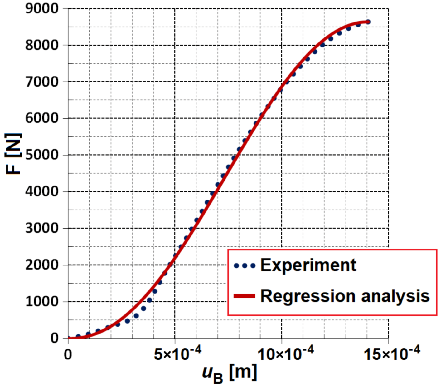
where the constant   m   is found by regression, e.g., in sw Matlab (Toolbox Curve Fitting) (see Table 4 and Figure 8).
Similar consensus to the experiment, as shown in Figure 8 (i.e., measurement No. 1), is also shown by other measurements from Table 3 and Table 4, which only confirms the correctness of the proposed model. Therefore, the introduction of a multi-parameter regression function does not seem to be necessary but is possible too.
From the knowledge of mechanics, relationship (8) can be generalized. Then, an important finding applies for the general value of the normal force N that
N = F E 2 m 1 cos   π   u u E m
Equation (9) applies for the entire length of the screwed thread L 2 = 0.09 m (see Figure 4), i.e., for the elongation u u B ;   u C , where points B and C are the ends of the screwed portion of the screw section and their displacements are u B and u C .
The relatively “simple” dependence ((8) or (9)) is encumbered by a minor error towards the experiment, and therefore is accurate enough.
For other needs, it is also appropriate to determine the derivative of the normal force
d N d u = π F E m u E 2 m sin π   u u E 1 cos π   u u E m 1 = π m F E sin π   u u E u E 1 cos π   u u E .  
Relationship (6) then results in the relationship for the continuously distributed reaction force
q N = N E A d N d u = π   m   N 2 sin π   u u E E A u E 1 cos π   u u E = π   m   F E 2 sin π   u u E 1 cos π   u u E 2 m 1 4 m E A u E .
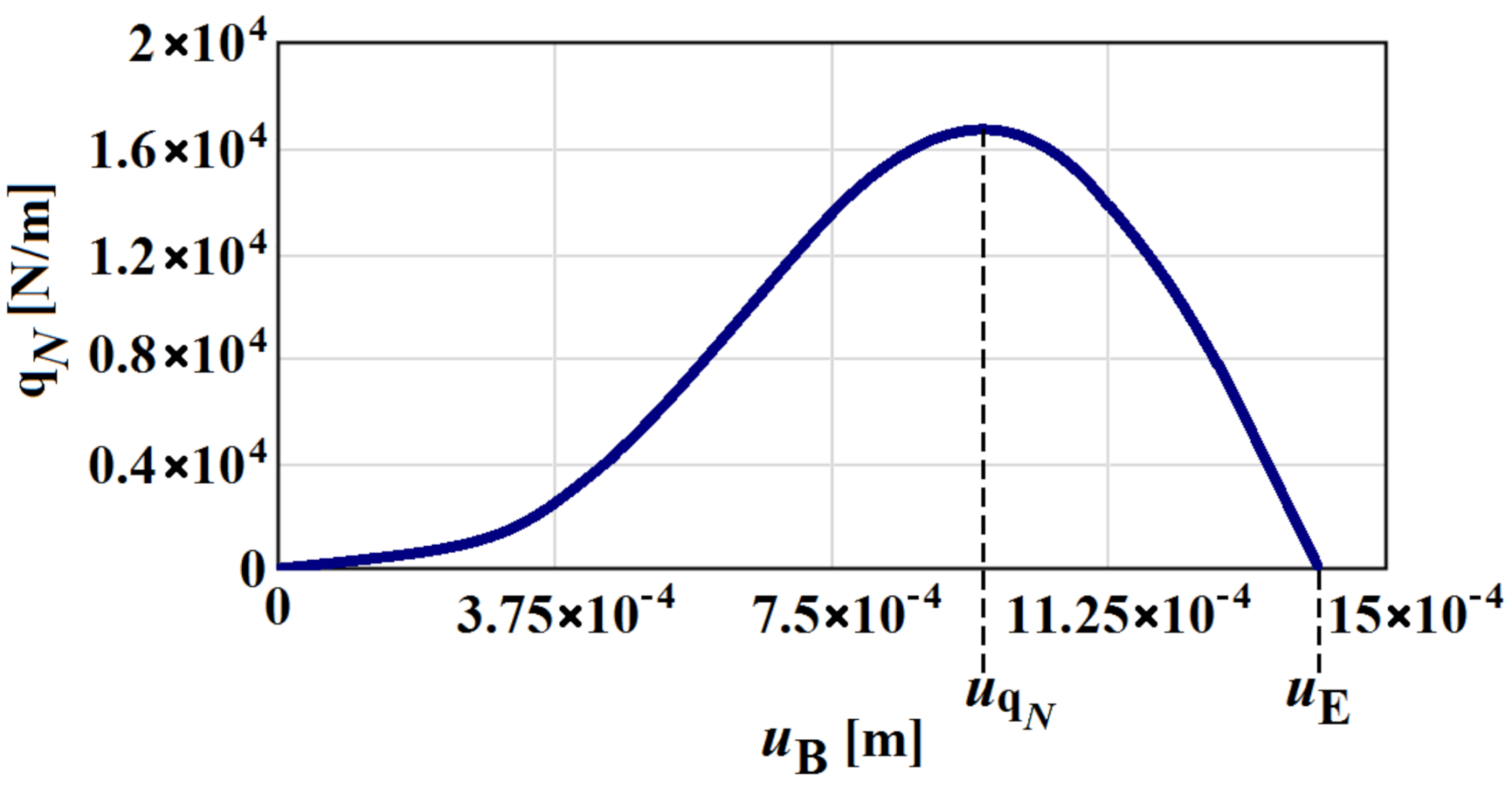
The determined dependence q N on the surface (in point B), i.e., the function q N = f u B , is shown in Figure 9. It is obvious that at the moment of the screw pulling, i.e., when u B = u E , the q N = 0 , which is in line with reality (disintegration of screw joints, confirmation of the theory of mechanics).
The position of the extreme value q N is given by the zero value of the first derivative (when d q N d x = 0), i.e., u q N =   u E π   acos 1 2 m 2 m (see Figure 9).

5. Determination of the Screw Elongation

It follows from Equations (2) and (9):
d u d x = F E E A 2 m 1 cos π   u u E m ,
i.e., with the solution d u 1 cos π   u u E m = F E E A 2 m   d x   + C , where C [m] is the integration constant, which is determined from the boundary condition x = 0 , u = u B 0 ; u E (see Figure 4).
The result obtained is valid for the selected value of the position of the threaded portion of the screw from the interval x 0 ; L 2 (see Figure 4) and, at the same time, according to the selected known value of the displacement measurement from the course of the pull-out test (i.e., according to the selected value u B ). Then, the displacement u in the general position can be determined and, therefore, u = f u B ,   x . A positive displacement direction (elongation), u and u B , is shown in Figure 4.
The solution of Equation (12) can also be done using a definite integral with a variable limit:
u B u d u 1 cos π   u u E m = F E E A 2 m 0 x d x   ,   where   x 0 ; L 2   and   u B 0 ; u E .
By determining the primitive function   G u [m]:
G u = d u 1 cos π   u u E m   ,
which is the higher transcendent function of elongation u (i.e., the solution of the integral exists, but can only be determined by numerical methods or by the development of infinite series), and relationship (13) can be rewritten as:
G u B G u = F E   x E A 2 m .
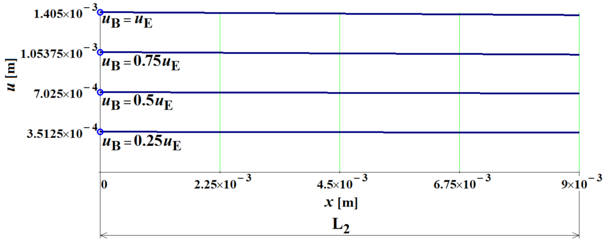
The searched displacement u = f u B ,   x is “hidden” in the implicit function G u and its determination is slightly more difficult but solvable. An example of the course of the dependence of u = f u B ,   x for measurement number 1 is shown in Figure 10.
From the course in Figure 10, it is clear that the dependencies u = f u B ,   x are approximately linear (practically constant) for the selected values of u B and decrease slowly with the distance x , which is not in conflict with numerical and other solutions in reference [25].

6. Discussion

The problem of several variants of the geometrical and material design of screw joints in the wood was solved in an analytical way by means of a newly designed tangential model of an elastic foundation (i.e., according to the authors Frydrýšek and Michenková). The results (see Equations (9), (11) and (15)) and, thus, the proposed elastic foundation model, are in very good correlation with the pull-out tests performed at our workplace (see Table 3, Table 4 and Figure 8). The validity of the tangential elastic foundation proposed by us is until the limit state is reached (pulling the screw out of the wood or screw breakage), while the anisotropic and inhomogeneous properties of the wood are also indirectly taken into account. The presented tangential foundation model applies to small screw deformations and small/large foundation deformations.
Thus, it is possible to replace the generally relatively complex 3D task of a screw joint (i.e., complicated mechanical contact with friction) using the tangential model of the elastic foundation we designed. This should lead to a substantial simplification and important acceleration of the calculation, e.g., the targeted replacement of the abovementioned non-linearity of the 3D screw joint task by a much simpler non-linearity of elastic foundation (introduction of non-linear springs according to (9), etc.). Therefore, the advantage of the elastic foundation is a significant and sufficiently precise simplification of the generally very complicated interaction of the screw and the fastener.
It is important to also verify the newly designed model on other (non-wood) joined materials. In fact, the tangential elastic foundation significantly simplifies the anisotropy or orthotropy and inhomogeneity of the joined material.
By utilizing the experience of biomechanics, which is also the main subject of research at our workplace, it is possible to apply it to bone screws used in medicine and veterinary (i.e., screws screwed into bones). Hence, the new tangential elastic foundation model is also used in biomechanics for verification and generalization.
In traumatology and orthopaedics, the pull-out tests of bone screws are mostly connected with the reliability assessment of screw joints. Bone screws are commonly used in implants for internal or external fracture fixation (see [12,13,15,16,19,24,25,27,28]). To date, works on bone screw pull-outs have focused mainly on cadaver, animal and artificial bones (healthy or osteoporotic) (see [14,17,26]). Osteoporosis means “porous bone”.
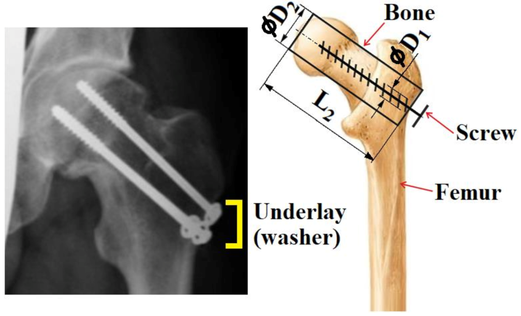
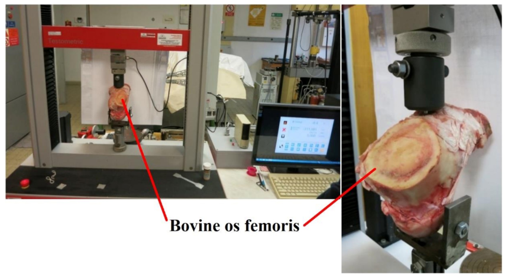
An analytical and experimental solution for pulling out bone screws from the proximal portions of human/bovine cadaveric bones (hip from caput femoris and collum femoris) is mentioned here (see Figure 11 and Figure 12 and references [15,18]). However, the issue of bones (although it has some resemblance to wood) is not the main subject of this article and therefore the results of bone screw joints are presented very briefly. In the future continuation of this work, the results of pull-out tests of bone screws will be published in connection to other similar biomechanical problems of screws.
The solution used the same type of tangential foundation model as in the previous section of this article, but for new measurements and a new regression (i.e., for new u B , F , u E , F E and m values). The same HB 6.5 (full cross section) and HB 7 (cannulated cross section) screws were also used, as above, and for various pre-drilling and tap selection options according to medical surgical procedures.
The screws were made by conventional machining or 3D printing with finishing operations using medical 1.4441 (AISI 316L) stainless steel and medical Ti6Al4V titanium alloy. For more details, see our references [15,18,27].
The findings (calculations and experiments) confirmed a very good consensus of the theory and practice of the tangential elastic foundation in the biomechanical role of the screw–bone interaction. Thus, it can be stated that the use of a tangential elastic foundation is suitable for general types of screw joints and general types of joined isotropic/orthotropic/anisotropic materials.
The mentioned biomechanical applications will be published in future.

7. Results

Since the abovementioned findings and analytical, experimental and numerical approaches have confirmed the theory and practice of the newly proposed tangential elastic foundation model, the following may be stated:
  • We have been able to derive the new theoretical solution of the differential equation of the screw joint using the tangential elastic foundation theory, including the determination of the boundary conditions and derivation of the analytical solution procedure.
  • The screw (beam on the elastic foundation) is subjected to tension/compression loading in this article.
  • Two types of screws (HB 6.5 and HB 7) were made of stainless steel 1.4441 (AISI 316L) and titanium alloy Ti6Al4V by machining technology and 3D printing + machining technology.
  • Experimental tests (pull-out tests) for joining dry spruce wood and bovine and human bones (i.e., three types of generally anisotropic and non-homogeneous materials) were carried out using pull-out tests up to limit states (screw breakage, pulling the screw out of the fasteners). The u B , F dependencies were obtained for 13 cases, and the limit failure states ( u E ,   F E ) were evaluated. Our experimental tests are in good agreement with different experiments with different materials (see [24,26,27,28]). However, it is advisable to perform more experiments.
  • A sufficient regression analysis of a sufficiently determined dependence of the normal force on the elongation (displacement) of the screw N =   F E 2 m   1 cos π   u u E m was performed, i.e., the determination of the m factor from the evaluation of the pull-out tests. Regression approximates the course of the experiment accurately enough for desired applicability (i.e., for interval u B 0 ; u E ).
  • Thus, the application of the tangential elastic foundation model can be generalized to the joining of diverse materials by different types of screws made of different materials (forming, 3D printing). The condition of such an application of the tangential foundation is the knowledge of the relationship N =   F E 2 m   1 cos π   u u E m for a given screw joint. However, this is only possible using the measurement evaluation.
  • The obtained results confirm the correctness of the proposed tangential elastic foundation as an alternative and simpler solution of the complex 3D task of mechanical contact with friction, which is undoubtedly the case of the screw joint. Instead of the task of strongly non-linear mechanical contact, the simpler use of a suitable number of non-linear springs satisfying the relationships N =   F E 2 m   1 cos π   u u E m or q N =   N E A d N d u can be applied. Such non-linear springs can be applied, for example, in nodes of the finite element mesh, etc. Thanks to the shortening of computational times, in addition to a simpler, more affordable and faster solution, it is also possible to apply the probabilistic approach very effectively in the design of the screw joint. Probabilistic approaches and probabilistic reliability assessments (based, e.g., on the Monte Carlo method and respecting the real variability of input and output variables) are in line with modern trends in science and technology (see [6,29,31,32,33]).
  • Other possible approximations of the dependencies N =   f u , for interval u B 0 ; u E , expressed by sine series, square roots of power series or other models, etc., are also other aspects of the research, but are not the subject of this article. For more details, see references [18,42].
  • Other applications of the tangential elastic foundation are also possible (shrink rings, earth screws, bone screws in traumatology and orthopaedics), and the biomechanical tasks (pulling screws out of the bone) are briefly mentioned in this article. For more information, see [12,15,29].
  • It is clear from the first results and applications that the new tangential foundation model, which is also characterized by continuously distributed reaction force q N = E A   d 2 u d x 2 , or q N =   N E A d N d u , offers a new alternative as a sufficiently accurate and relatively simple solution to the real complex interaction of the screw and the fasteners. It is also advantageous that large deformations, non-linearities, anisotropy or inhomogeneities can occur in this model of tangential foundation.
  • It is also appropriate to focus on the future. In other models of elastic foundations, the influence of self-weight and dynamics (see [21]) can also be taken into account (however, this would lead to solving partial differential equations in the most complex tasks). The application of large deformations (logarithmic strains ε l o g = ln ( 1 +   d u d x ) applied in Equation (1)), etc. is significant, as well as the combined bending + tension/pressure loads (see [15]) or torsion + bending + tension/pressure loads and impact loads [21], which are common, and not only in mechanical, building or biomechanical structures. This will be the subject of further research to follow up this article. Other complex biomechanical/mechanical applications are possible too, for example, see [12,14,26].
  • After further experiments, our model can be applied as an alternative method in design codes, for example, see [3], etc.

8. Conclusions

The problem of the solution of beams placed on an elastic foundation is very extensive and of great importance in the theoretical and practical field of science and technology. Typical applications are predominantly in bending tasks. However, this article focuses on new, original and highly efficient tension/pressure load applications.
A new model of a tangential foundation has been proposed (i.e., the differential equation and its solution) which is applicable to a beam (screw) drilled (placed) in this type of the foundation and subjected to tension/pressure. Properties of this foundation were investigated analytically (compilation and solution of a differential equation including boundary conditions), experimental execution of pull-out tests and finding a suitable simple and sufficiently accurate regression N =   F E 2 m   1 cos π   u u E m of the dependence of normal forces N on elongation (displacement) u of the screw.
The scope of application of the new tangential elastic foundation is up to the limit failure state of the screw joint (i.e., either screw breakage or the screw pulling out of the fastener).
HB 6.5 and HB 7 screws made of stainless steel 1.4441 (AISI 316L) and titanium alloy Ti6Al4V were chosen as testing tasks. These screws were made using conventional machining methods and also by 3D printing with machining as a finishing operation.
Dry spruce wood and human/bovine cadaveric bones were chosen as the fasteners.
A certain variability of the technological procedure of placing (screwing) the screw was selected (the size of the pre-drilled holes (0.0032 m; 0.0055 m) for the thread, the use of the screw taps in the bones according to the surgical procedures in orthopaedics and traumatology).
From the above, it is clear that the newly designed tangential foundation model can be used for anisotropic/orthotropic or isotropic materials and it depends on the knowledge of the course of pull-out tests of screws in the fasteners.
In all test cases, a high consensus with the experiment (pull-out tests) was achieved, and the proposed tangential elastic foundation model is suitable for both technical and biomechanical applications.
Uniaxial pull-out tests afford an accurate method of comparing and evaluating screw joints. Our acquired results (dependencies, limit states u E ;   F E , regressions, etc.) are in good agreements with other references. For example, see [10,16,24,25,27].
There are also other possible directions of development in theoretical and application areas, such as biomechanics (i.e., applications in traumatology and orthopaedics, see [12,13,14,15,17,19,24,25,26,28,29,30], etc.), wooden structures (see [1,2,6,8]), plastics and probabilistic reliability assessment of screw joints (see [3,6,29,31,32,33], etc).

Author Contributions

Conceptualization: K.F. and Š.M.; Investigation: Š.M., K.F. and L.P.; Formal analysis: J.K., K.P.D. and R.M.; Methodology: J.F. and K.F.; Resources: A.T.; Supervision: P.K., L.H. and L.B.; Validation: R.J., J.P. and T.H.; Writing—review & editing: T.H. and K.F. All authors have read and agreed to the published version of the manuscript.

Funding

This article was supported by Czech project SP2021/66 and by projects CZ.02.1.01/0.0/17_049/0008407 and CZ.02.1.01/0.0/0.0/17_049/0008441 within the Operational Programme Research, Development and Education financed by the European Union and from the state budget of the Czech Republic.

Data Availability Statement

Not available.

Conflicts of Interest

The authors declare no conflict of interest.

References

  1. Aicher, S.; Gustafsson, P.J.; Wolf, M. Load Displacement and Bond Strength of Glued-in Rods in Timber Influenced by Adhesive, Wood Density, Rod Slenderness and Diameter. In Proceedings of the 1st International RILEM Symposium on Timber Engineering, Stockholm, Sweden, 13–15 September 1999; pp. 369–379. [Google Scholar]
  2. Breyer, D.E. Design of Wood Structures; McGraw-Hill: New York, NY, USA, 1988; pp. 1–680. ISBN 978-0070076754. [Google Scholar]
  3. European Standard EN 1995-1-1 Eurocode 5, 2004: Design of Timber Structures, Authority: The European Union Per Regulation 305/2011, Directive 98/34/EC, Directive 2004/18/EC. Available online: http://www.phd.eng.br/wp-content/uploads/2015/12/en.1995.1.1.2004.pdf (accessed on 21 April 2021).
  4. Hicks, T.G. Civil Engineering Formulas; McGraw-Hill: New York, NY, USA, 2010; pp. 1–395. ISBN 978-0-07-161470-2. [Google Scholar]
  5. Khurmi, R.S.; Gupta, J.K. Machine Design; Eurasia Publishing House: Kolkata, India, 2005; pp. 1–1230. ISBN 978-8121925372. [Google Scholar]
  6. Lokaj, A.; Vavrušová, K.; Rykalová, E. Application of Laboratory Tests Results of Dowel Joints in Cement-Splinter Boards VELOX into the Fully Probabilistic Methods (SBRA Method). Appl. Mech. Mater. 2012, 137, 95–99. [Google Scholar] [CrossRef]
  7. Mackerle, J. Finite element analyses in wood research: A bibliography. Wood Sci. Technol. 2005, 39, 579–600. [Google Scholar] [CrossRef]
  8. Vavrušova, K.; Mikolášek, D.; Lokaj, A.; Klajmonová, K.; Sucharda, O.; Pařenica, P. Determination of Carrying Capacity of Steel-Timber Joints with Steel Rods Glued-In Parallel to Grain; Wood Research: Karlova Ves, Slovakia, 2016; Volume 61, pp. 733–740. [Google Scholar]
  9. Sucharda, O.; Smirakova, M.; Vaskova, J.; MatečkovÁ, P.; Kubosek, J.; Cajka, R. Punching Shear Failure of Concrete Ground Supported Slab. Int. J. Concr. Struct. Mater. 2018, 12, 36. [Google Scholar] [CrossRef]
  10. Hu, Y.; Shen, L.; Nie, S.; Yang, B.; Sha, W. FE simulation and experimental tests of high-strength structural bolts under tension. J. Constr. Steel Res. 2016, 126, 174–186. [Google Scholar] [CrossRef] [Green Version]
  11. Začal, J.; Jančar, L. Effect of Temperature on Bolt Working Load of Pressure Vessels. In Advances in Mechanical Engineering; Springer: Berlin/Heidelberg, Germany, 2019; pp. 433–441. [Google Scholar]
  12. Bajtek, V.; Frydrysek, K.; Pleva, L. Stochastic Strength Analysis of Compression Headless Screw. MM Sci. J. 2020, 2020, 3837–3840. [Google Scholar] [CrossRef]
  13. Čada, R.; Frydrýšek, K.; Sejda, F.; Demel, J.; Pleva, L. Analysis of Locking Self-Taping Bone Screws for Angularly Stable Plates. J. Med. Biol. Eng. 2017, 37, 612–625. [Google Scholar] [CrossRef] [PubMed] [Green Version]
  14. Catapano, S.; Ferrari, M.; Mobilio, N.; Montanari, M.; Corsalini, M.; Grande, F. Comparative Analysis of the Stability of Prosthetic Screws under Cyclic Loading in Implant Prosthodontics: An In Vitro Study. Appl. Sci. 2021, 11, 622. [Google Scholar] [CrossRef]
  15. Frydrýšek, K.; Šír, M.; Pleva, L. Strength Analyses of Screws for Femoral Neck Fractures. J. Med. Biol. Eng. 2018, 38, 816–834. [Google Scholar] [CrossRef] [Green Version]
  16. Kwon, J.; Ha, M.H.; Lee, M.G. Alternative Pedicle Screw Design via Biomechanical Evaluation. Appl. Sci. 2020, 10, 4746. [Google Scholar] [CrossRef]
  17. Loi, F.; Córdova, L.A.; Pajarinen, J.; Lin, T.-H.; Yao, Z.; Goodman, S.B. Inflammation, fracture and bone repair. Bone 2016, 86, 119–130. [Google Scholar] [CrossRef] [Green Version]
  18. Michenková, Š. Nonlinear Problems of the Beams on Elastic Foundation (Nelineární úlohy nosníků na pružném podkladu). Ph.D. Thesis, VSB—Technical University of Ostrava, Faculty of Mechanical Engineering, Department of Applied Mechanics, , Ostrava, Czechia, 2017; pp. 1–170. (In Czech). [Google Scholar]
  19. Niculescu, B.; Faur, C.I.; Tataru, T.; Diaconu, B.M.; Cruceru, M. Investigation of Biomechanical Characteristics of Orthopedic Implants for Tibial Plateau Fractures by Means of Deep Learning and Support Vector Machine Classification. Appl. Sci. 2020, 10, 4697. [Google Scholar] [CrossRef]
  20. Available online: https://www.medin.cz/ (accessed on 21 April 2021).
  21. Marasová, D., Jr. Experimental Research on Dynamic Impact Loading Using Impact Rods. Int. Multidiscip. Sci. Geoconf. Sgem 2020, 20, 103–110. [Google Scholar]
  22. Van De Kamp, T.; Vagovič, P.; Baumbach, T.; Riedel, A. A Biological Screw in a Beetle’s Leg. Science 2011, 333, 52. [Google Scholar] [CrossRef]
  23. Autoritatea Pentru Administrarea Activelor Statului (AAAS). Karlsruhe Institute of Technology: Nature Uses Screws and Nuts. Available online: https://www.eurekalert.org/pub_releases/2011-07/haog-kio070111.php (accessed on 21 April 2021).
  24. Costa, F.; Ortolina, A.; Galbusera, F.; Cardia, A.; Sala, G.; Ronchi, F.; Uccelli, C.; Grosso, R.; Fornari, M. Pedicle screw cement augmentation. A mechanical pullout study on different cement augmentation techniques. Med. Eng. Phys. 2016, 38, 181–186. [Google Scholar] [CrossRef]
  25. Foley, W.L.; Frost, D.E.; Paulin, W.B., Jr.; Tucker, M.R. Uniaxial pullout evaluation of internal screw fixation. J. Oral Maxillofac. Surg. 1989, 47, 277–280. [Google Scholar] [CrossRef]
  26. Patel, P.S.D.; Shepherd, D.E.T.; Hukins, D.W.L. Axial and angled pullout strength of bone screws in normal and osteoporotic bone material. In Proceedings of the 13th International Conference on Biomedical Engineering, Singapore, 3–6 December 2008; pp. 1619–1622. [Google Scholar]
  27. Varghese, V.; Krishnan, V.; Kumar, G.S. Comparison of pullout strength of pedicle screws following revision using larger diameter screws. Med. Eng. Phys. 2019, 74, 180–185. [Google Scholar] [CrossRef] [PubMed]
  28. Zdero, R.; Aziz, M.S.; Nicayenzi, B. Pullout Force Testing of Cortical and Cancellous Screws in Whole Bone. In Experimental Methods in Orthopaedic Biomechanics; Elsevier BV: Amsterdam, The Netherlands, 2017; pp. 117–132. [Google Scholar]
  29. Frydrýšek, K.; Tvrdá, K.; Jančo, R.; Čajka, R.; Fries, J.; Michenková, S.; Nikodvm, M.; Theisz, G.; Pleva, L.; Manas, P.; et al. Handbook of Structures on Elastic Foundation; VSB—Technical University of Ostrava: Ostrava, Czech Republic, 2013; ISBN 978-80-248-3238-8. [Google Scholar]
  30. Morávkova, Z.; Tomečková, I.; Frydrýšek, K. Beam rested on unilateral elastic foundation—(Theory, experiments and finite element approach). Eng. Mech. 2017, 670–673. [Google Scholar]
  31. Frydrýšek, K.; Václavek, L. Stochastic Computer Approach Applied in the Reliability Assessment of Engineering Structures. Adv. Hum. Factorsbus. Manag. Train. Educ. 2016, 451, 121–129. [Google Scholar] [CrossRef]
  32. Marek, P.; Brozzetti, J.; Gustar, M.; Elishakoff, I. Probabilistic Assessment of Structures using Monte Carlo Simulations. Appl. Mech. Rev. 2002, 55, B31–B32. [Google Scholar] [CrossRef]
  33. Tvrdá, K. Foundation plate on the elastic half-space, deterministic and probabilistic approach. MATEC Web Conf. 2017, 107, 58. [Google Scholar] [CrossRef] [Green Version]
  34. Cárach, J.; Hloch, S.; Petrů, J.; Muller, M.; Hromasová, M.; Nag, A.; Čuha, D.; Hlaváček, P.; Hatala, M.; Kratochvíl, J.; et al. Evaluation of physical phenomena and surface integrity during hydroabrasive disintegration of the rotating workpiece with feedback loop control. Measurement 2019, 134, 586–594. [Google Scholar] [CrossRef]
  35. Kratochvíl, J.; Sadílek, M.; Musil, V.; Pagáč, M.; Stančeková, D. The Effectiveness of Strategies Printing Printer Easy 3D Maker. Adv. Sci. Technol. Res. J. 2018, 12, 197–205. [Google Scholar] [CrossRef]
  36. Losertová, M.; Štamborská, M.; Lapin, J.; Mareš, V. Comparison of Deformation Behavior of 316L Stainless Steel and Ti6Al4V Alloy Applied in Traumatology. Metalurgija 2016, 55, 667–670. [Google Scholar]
  37. Petrů, J.; Zlámal, T.; Špalek, F.; Čep, R. Surface Microhardening Studies on Steels After High Feed Milling. Adv. Sci. Technol. Res. J. 2018, 12, 222–230. [Google Scholar] [CrossRef]
  38. Slíva, A.; Brázda, R.; Procházka, A.; Martynková, G.S.; Barabaszová, K. Čech Investigation of Geometric Properties of Modified Titanium White by Fluidisation for Use in the Process of Transport, Handling, Processing and Storage. J. Nanosci. Nanotechnol. 2019, 19, 2997–3001. [Google Scholar] [CrossRef] [PubMed]
  39. Václav, Š.; Sivtsev, N.S.; Senderská, K. Investigation of Stress-Strain State of the Workpiece at Gauge Burnishing of its Holes. Adv. Sci. Technol. Res. J. 2017, 11, 211–222. [Google Scholar] [CrossRef] [Green Version]
  40. Winczek, J.; Gawronska, E.; Murčinková, Z.; Hatala, M.; Pavlenko, S.; Makles, K. Analysis of thermomechanical states in single-pass GMAW surfaced steel element. In Proceedings of the AIP Conference Proceedings, Bydgoszcz, Poland, 9–11 May 2017; Volume 1822, p. 020015. [Google Scholar]
  41. Hetényi, M. Beams on Elastic Foundation, 2nd ed.; University of Michigan Press: Ann Arbor, MI, USA, 1964. [Google Scholar]
  42. Liu, Q.; Ma, J. Analytical Model for Beams on Elastic Foundations Considering the Coupling of Horizontal and Vertical Displacements. J. Eng. Mech. 2013, 139, 1757–1768. [Google Scholar] [CrossRef]
  43. 50 kN Machines. Available online: https://www.testometric.co.uk/50kn/ (accessed on 21 April 2021).
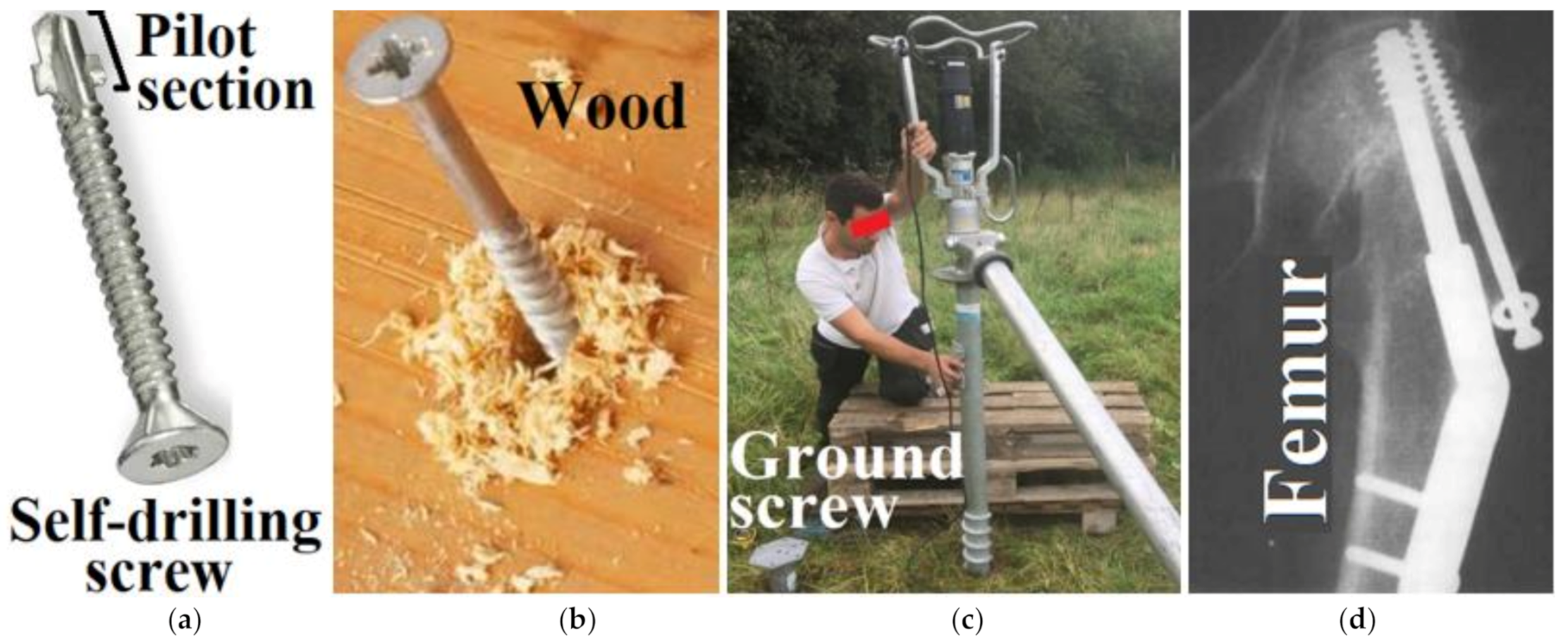
Figure 1. Common applications and design of engineering screw joints.
Applsci 11 05616 g001
Figure 2. Elastic foundation due to the loads (points 1 and 2 are moved to new positions 1* and 2*). (a) Bending according to Winkler (distributed reaction force in foundation q R = k v in linear cases); (b) Tension/pressure—new tangential model according to Frydrýšek and Michenková (distributed reaction force q N = k N u in linear cases, where k N [Pa] is elastic foundation stiffness, u [m] is axial displacement/elongation and F i [N] is a tensile/compression force).
Applsci 11 05616 g002
Figure 3. Section of the beam (screw) resting on a tangential elastic foundation, where N [N] is a normal (axial, internal) force.
Applsci 11 05616 g003
Figure 4. Measurements and testing specimen (the sketch not shown in actual scale).
Applsci 11 05616 g004
Figure 5. Pull-out test, measurement No. 1. (a) Dependence of tensile force F on screw elongation   u B ; (b) the pulled out screw (end of measurement).
Applsci 11 05616 g005
Figure 6. Pull-out test: A typical dependence of tensile force F on the screw elongation u B (determination of extreme values of the pull-out test for screws in the wood).
Applsci 11 05616 g006
Figure 7. Pull-out test, measurement No. 6 (screw breakage, end of measurement).
Applsci 11 05616 g007
Figure 8. Pull-out test, measurement No. 1: Dependence of tensile force F on screw elongation u B (the experiment and its approximation by regression function F = N B =   F E 2 m   1   cos π   u B u E m for interval u B 0 ; u E ).
Applsci 11 05616 g008
Figure 9. The course of the calculated continuous tangential reaction q N at the base at point B of the screw (measurement No. 1), see Figure 5.
Applsci 11 05616 g009
Figure 10. The course of the screw elongation dependence u = f u B ,   x for measurement No. 1 (i.e., the solution of Equation (15)).
Applsci 11 05616 g010
Figure 11. Biomechanics of human os femoris with factura collum femoris, osteosynthesis and application of a bone screw in connection with experiments.
Applsci 11 05616 g011
Figure 12. Biomechanics of bovine os femoris, bone screw application and the pull-out test.
Applsci 11 05616 g012
Table 1. Basic material information on the applied screws.
MaterialModulus of Elasticity E [Pa]Yield Limit [MPa]Fracture Limit [MPa]
1.44412.1 × 1011892977
Ti6Al4V1.06 × 10119191034
Table 2. Basic material information on the applied cancellous screws (see [20]).
Self-Tapping Cancellous Bone Screw HB6.5SStAB
Applsci 11 05616 i00112979691145 mm32 mm
12979692150 mm
12979693155 mm
12979694160 mm
12979695165 mm
12979696170 mm
12979697175 mm
12979698180 mm
12979699185 mm
Thread diameter 6.5 mm12979700190 mm
Shank diameter 4.5 mm12979701195 mm
Core diameter 3 mm129797021100 mm
Head diameter 8 mm129797031105 mm
Drill bit for threaded hole 3.2/3.75 mm129797041110 mm
Screwdriver Hex key 3.5 mm129797051115 mm
Material: Stainless steel AISI 316 L (DIN 1.4441/316 L medical) or titanium alloy (Ti6Al4V). Dimension “B” = L 2 .129797061120 mm
Cancellous Bone Screw HB7SStAB
Applsci 11 05616 i00212979821040 mm32 mm
12979822045 mm
12979823050 mm
12979824055 mm
12979825060 mm
12979826065 mm
12979827070 mm
12979828075 mm
12979829080 mm
12979830085 mm
12979831090 mm
Thread diameter 7 mm12979832095 mm
Shank diameter 5 mm129798330100 mm
Core diameter 3.5 mm129798340105 mm
Head diameter 8 mm129798350110 mm
Drill bit for threaded hole 4 mm129798360115 mm
Screwdriver Hex key 3.5 mm129798370120 mm
Cannulation 1.8 mm129798380125 mm
Material: Stainless steel AISI 316 L (DIN 1.4441/316 L medical) or titanium alloy (Ti6Al4V). Dimension “B” = L 2 .129798390130 mm
Table 3. Pull-out test results (Picea abies wood, moisture about 10%).
Measurement
Measurement NumberScrew TypeScrew MaterialPre-Drilled Hole Diameter [m]Limit StateDamage Limit State Description
F E   [ N ] u E   [ m ]
1HB 6.51.4441 (AISI 316L)0.003286340.001405Pulling the screw out of the wood
2HB 6.5Ti6Al4V0.00474750.001666
3HB 71.4441 (AISI 316L)0.00485410.001527Screw breakage
4HB 7Ti6Al4V0.004586490.001638Pulling the screw out of the wood
5HB 6.51.4441 (AISI 316L)0.00487700.001707
6HB 6.51.4441 (AISI 316L)0.00489420.001468Screw breakage
7HB 6.51.4441 (AISI 316L)0.00482790.00114Pulling the screw out of the wood
8HB 71.4441 (AISI 316L)0.00573900.001385
9HB 71.4441 (AISI 316L)0.00576060.001544
10HB 6.5Ti6Al4V0.00573220.001906
11HB 6.5Ti6Al4V0.00573810.001339
12HB 7Ti6Al4V0.005591050.001804
13HB 7Ti6Al4V0.005594810.002157Screw breakage
Table 4. The pull-out test results (a simple one-parameter approximation of measured data).
Measurement Number Approximation   N B = F E 2 m 1 c o s π   u B u E m
RegressionMeasurement (Limit States), See also Table 3
m [1] F E   [ N ] u E   [ m ]
11.07886340.001405
20.513974750.001666
30.787685410.001527
40.512886490.001638
50.673987700.001707
60.749989420.001468
70.62182790.00114
80.664873900.001385
90.750676060.001544
101.09573220.001906
110.512273810.001339
120.615891050.001804
130.534794810.002157
Publisher’s Note: MDPI stays neutral with regard to jurisdictional claims in published maps and institutional affiliations.