
Development of Modular Bio-Inspired Autonomous Underwater Vehicle for Close Subsea Asset Inspection

 ,
,  ,
,  , , ,
, , ,  , ,
, , 
Abstract
1. Introduction
2. Motivation and Background
3. Robofish Design
3.1. Vehicle Requirements
- University of York (Intelligent Systems and Nanoscience Group and Underwater Communication Group)
- University of Strathclyde (Computational Fluid Dynamics and Fluid Structure Interaction Research Group)
- Supergen ORE Hub
- PicSea Ltd. (Edinburgh, Scotland)
- EC-OG Ltd. (Bridge of Don, Scotland)
- Offshore Renewable Energy Catapult
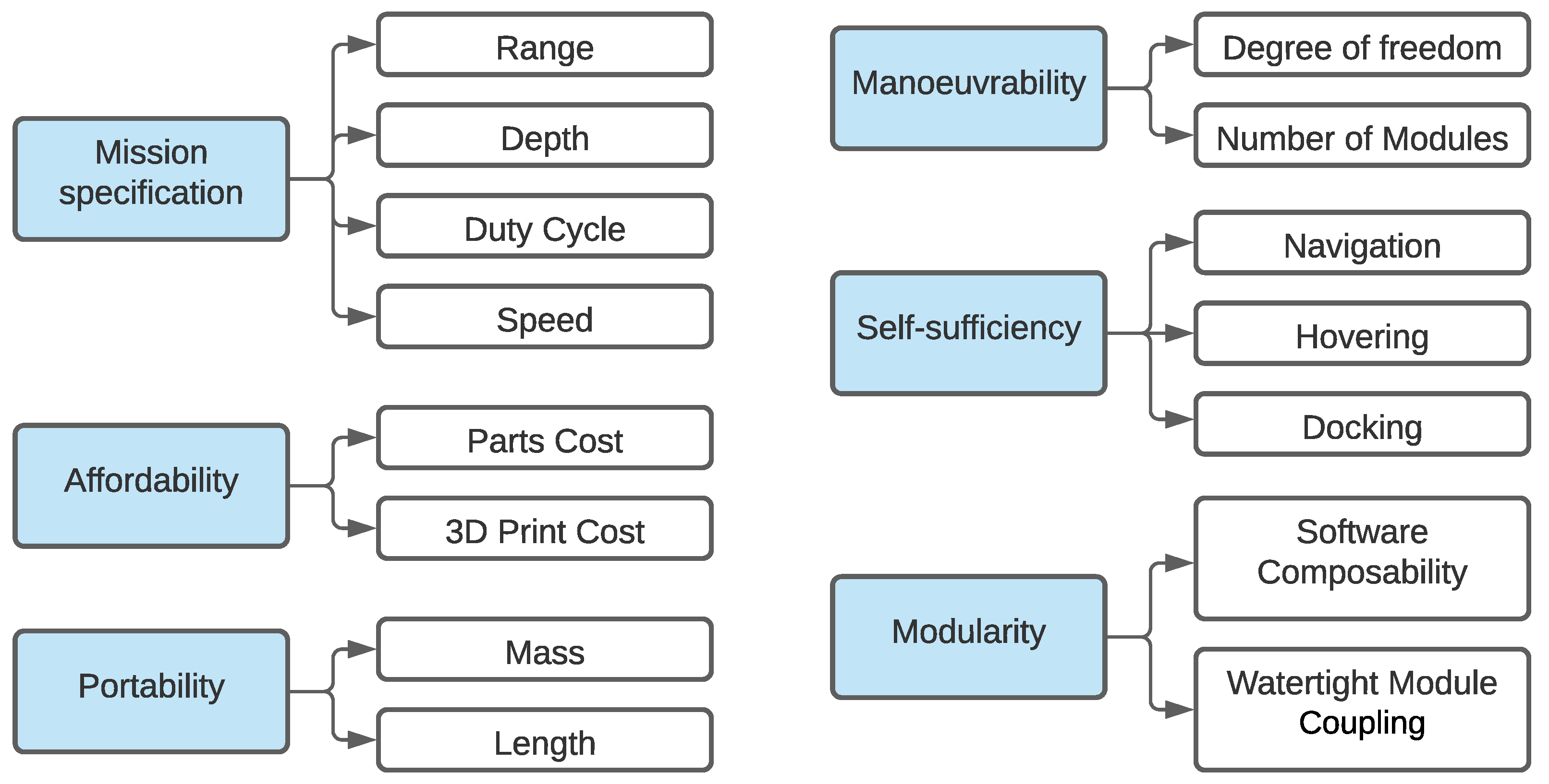
- Manoeuvrability
- Affordability
- Portability
- Modularity
- Self-sufficiency
3.2. Key Performance Attributes
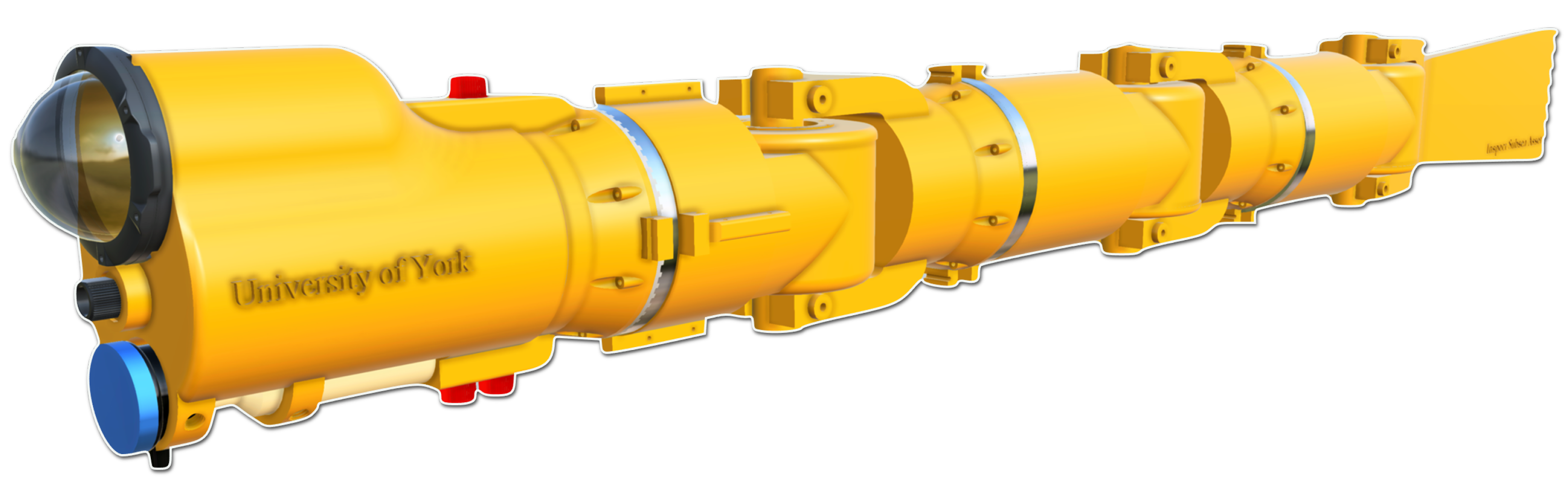
Design a low-cost, modular AUV to perform underwater inspection around complex structures. To keep costs at minimum, off-the-shelf parts and accessible additive manufacturing technologies will be used. The vehicle will be easy to launch, capture videos, recharge and return to a home location with minimum or no human intervention.
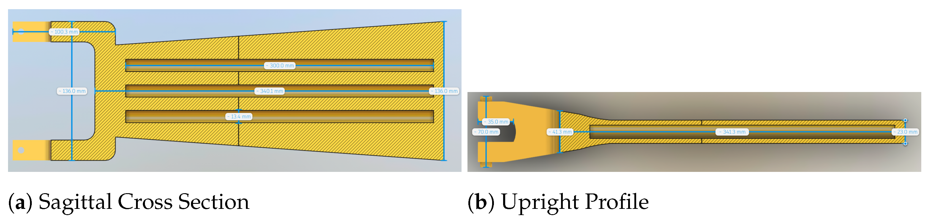
3.3. Mechanical Design
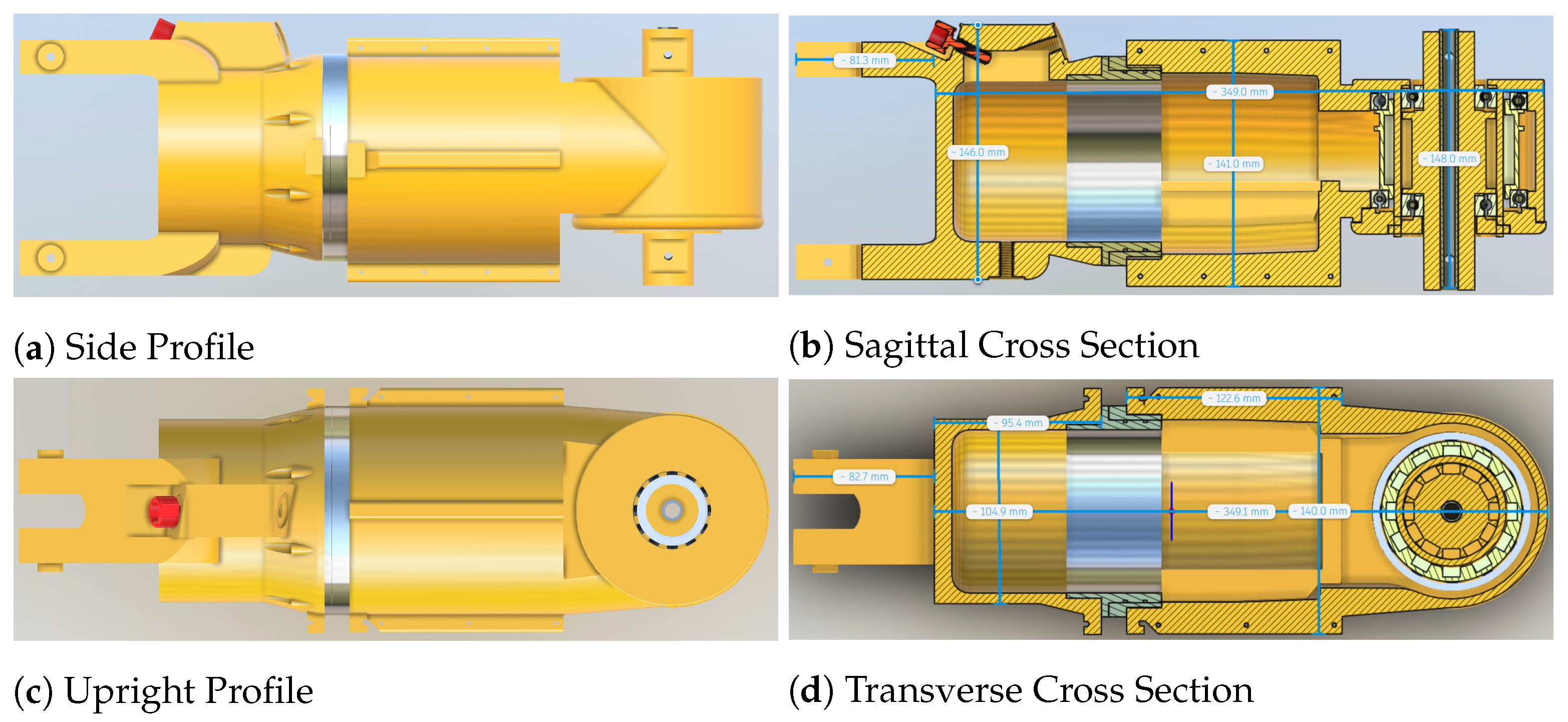
3.3.1. Body Segment
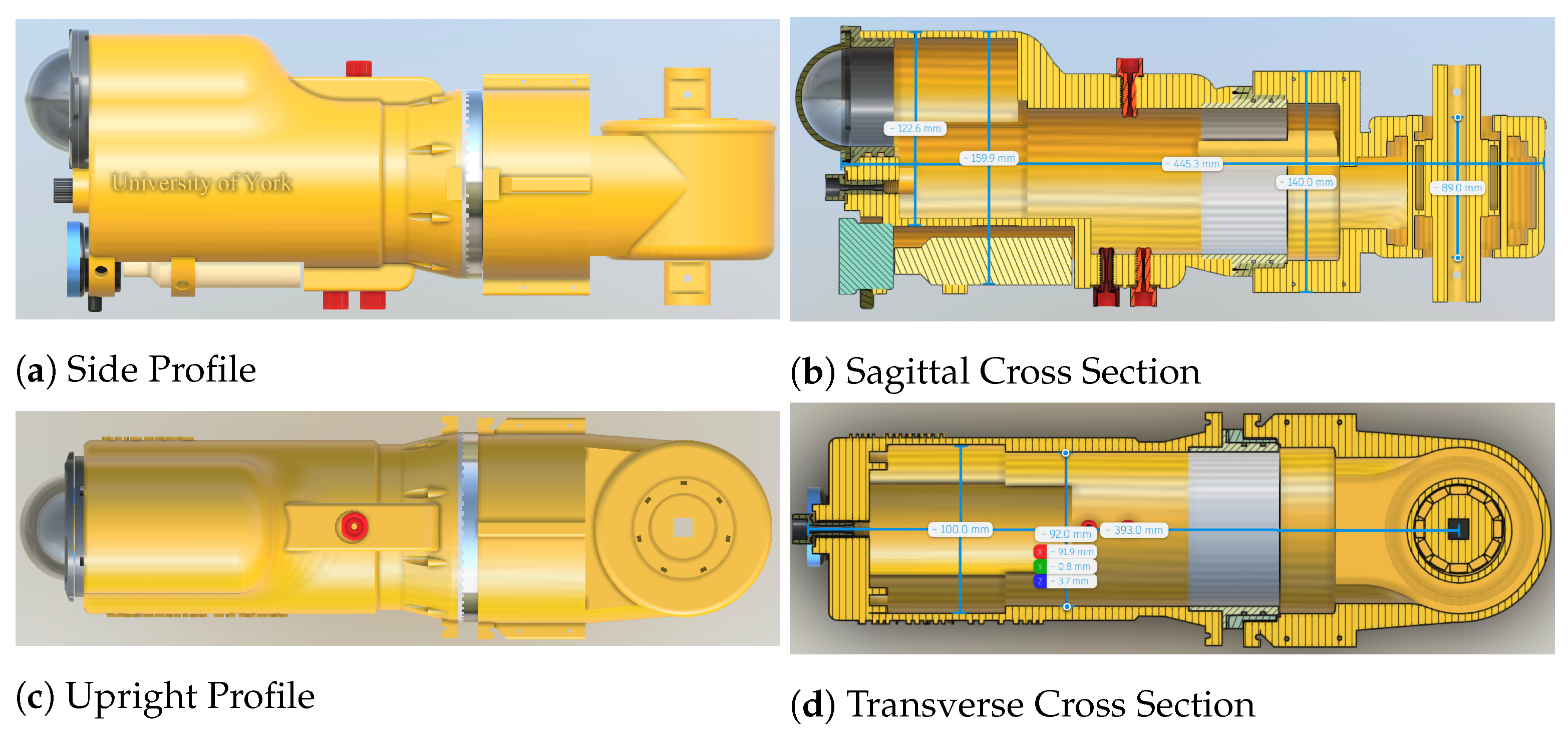
3.3.2. Head
3.3.3. Tail
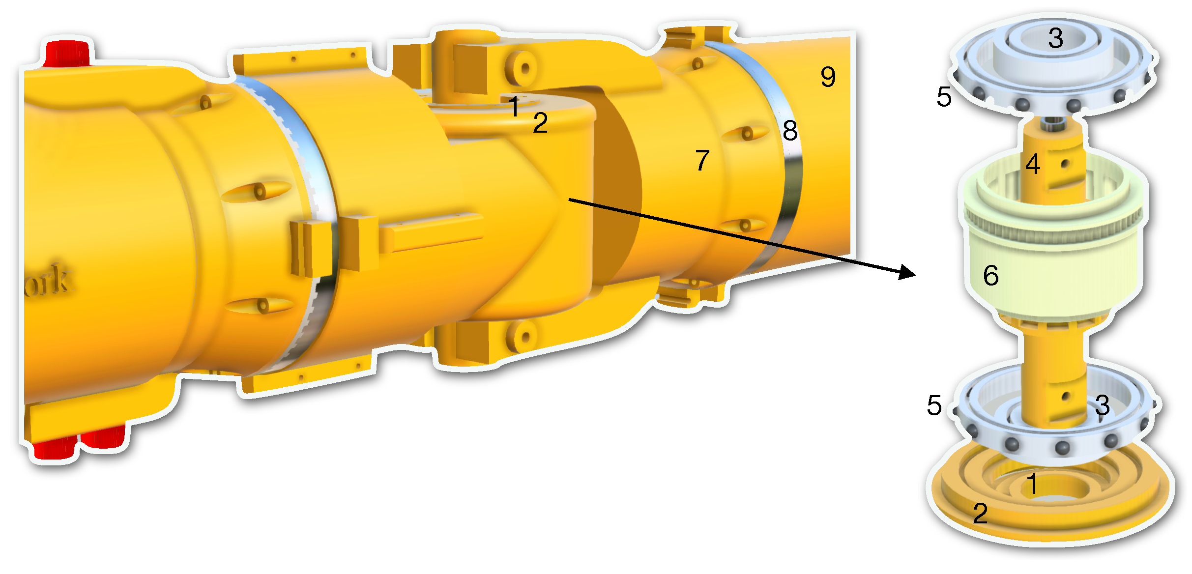
3.3.4. Magnetic Coupling Joint
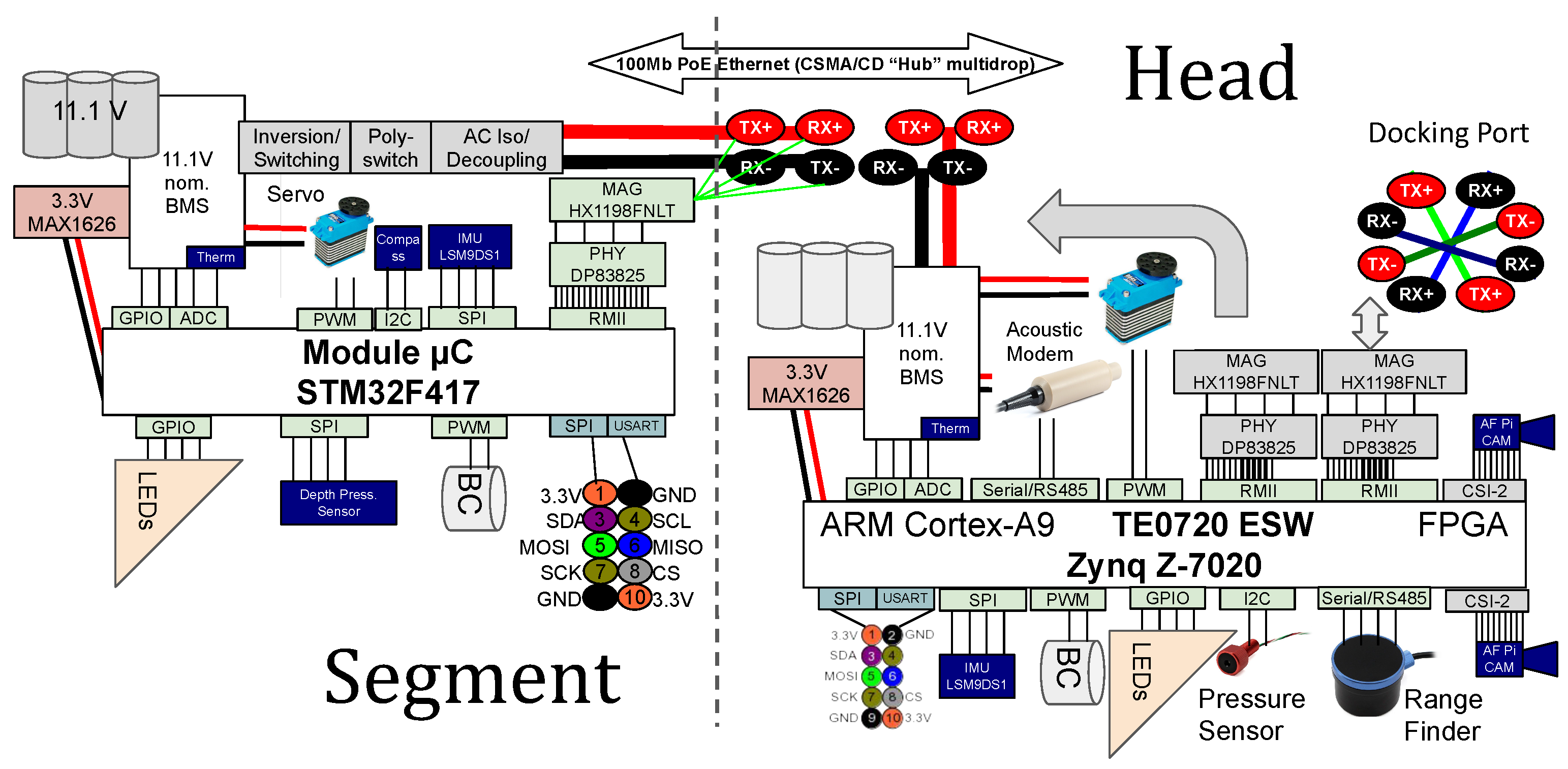
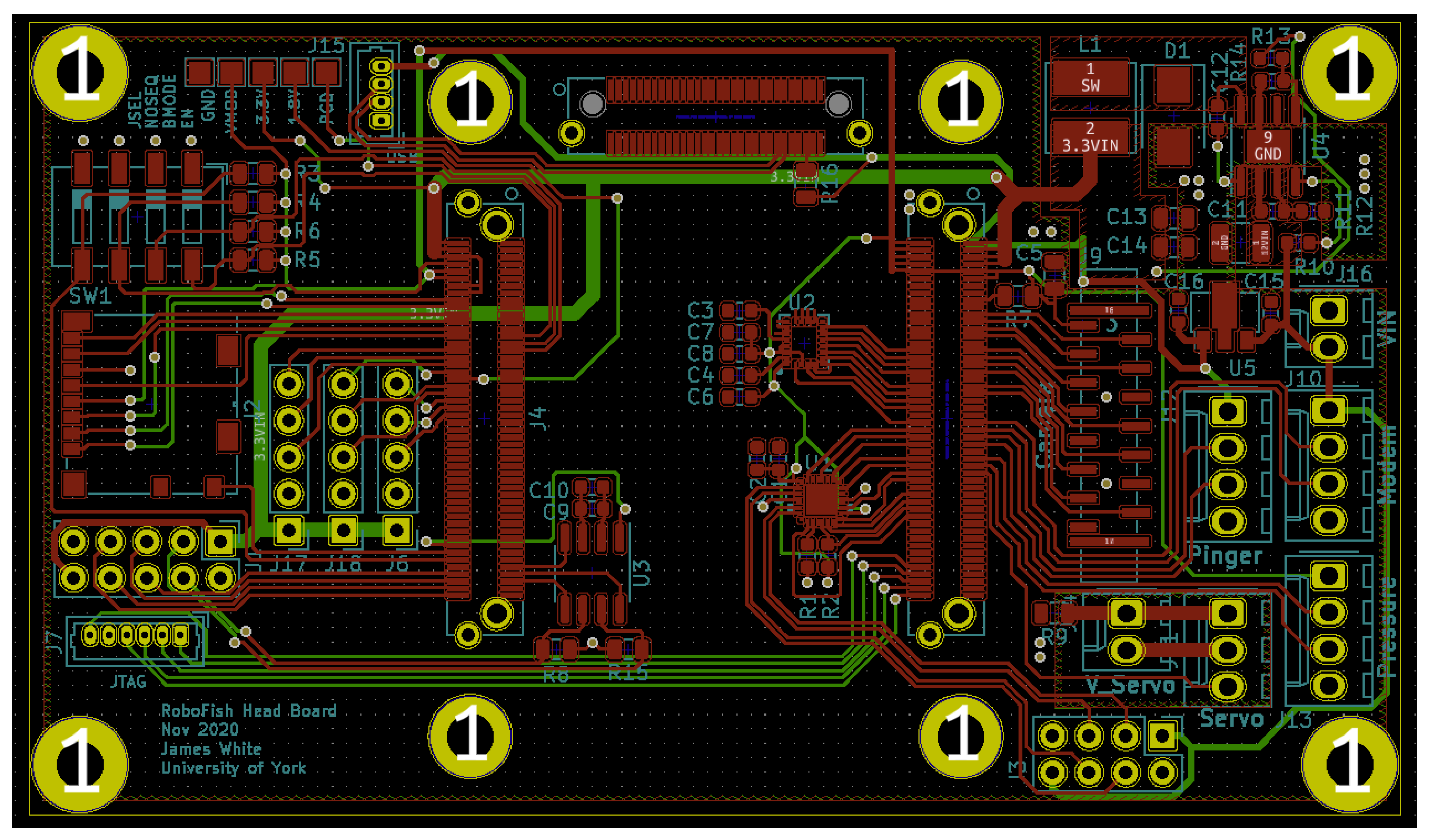
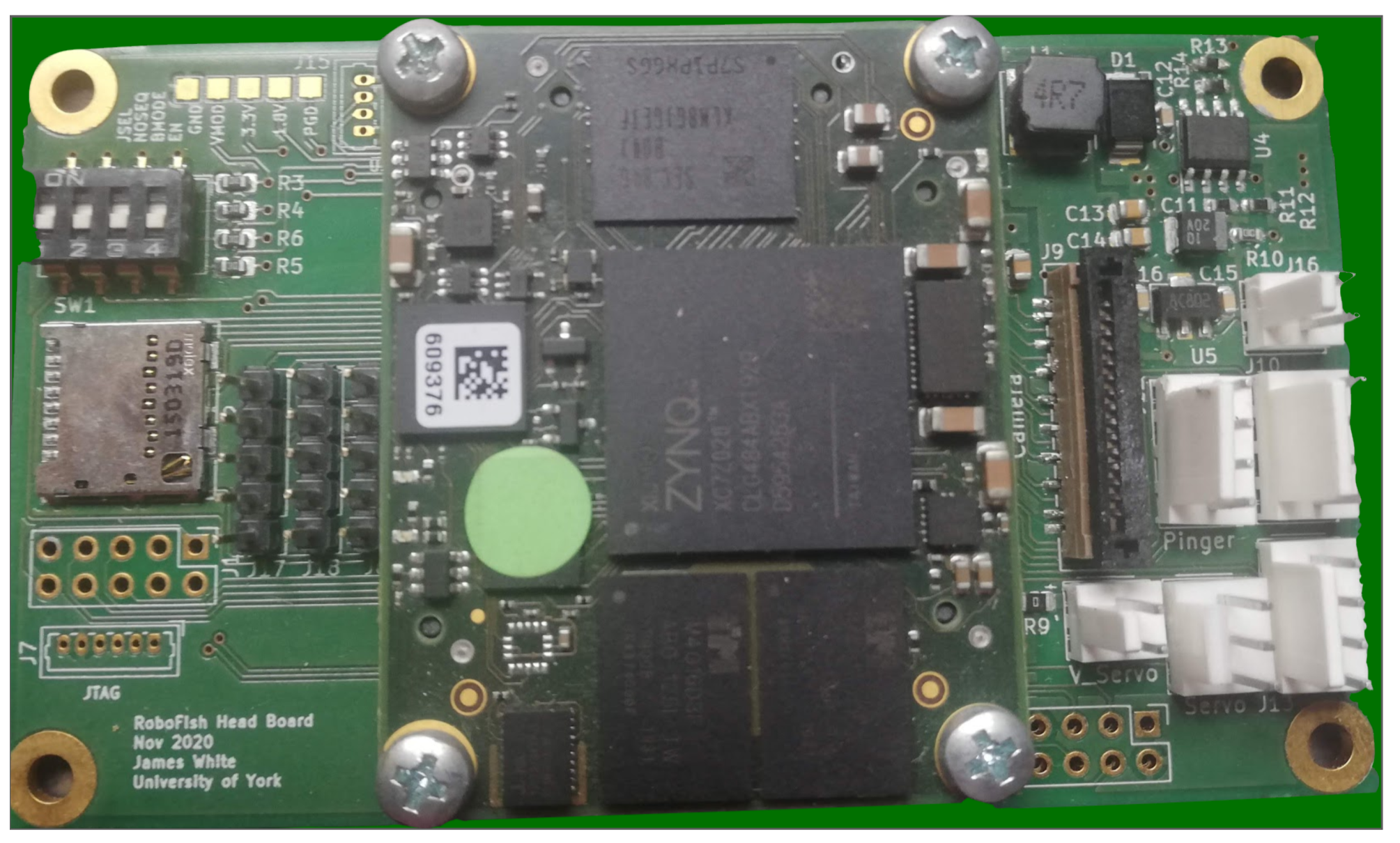
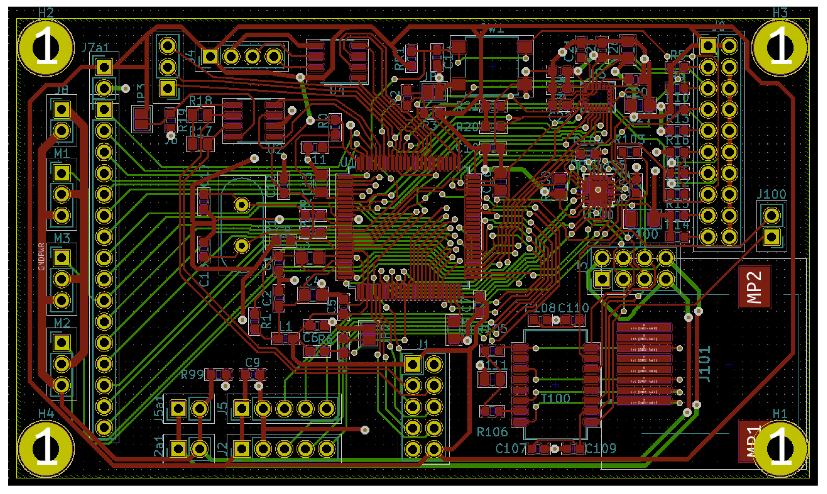
3.4. Electronic Design
3.4.1. Requirements
3.4.2. Hardware Choices
3.4.3. Hardware Implementation
4. Underwater Vision
5. Acoustic Communication
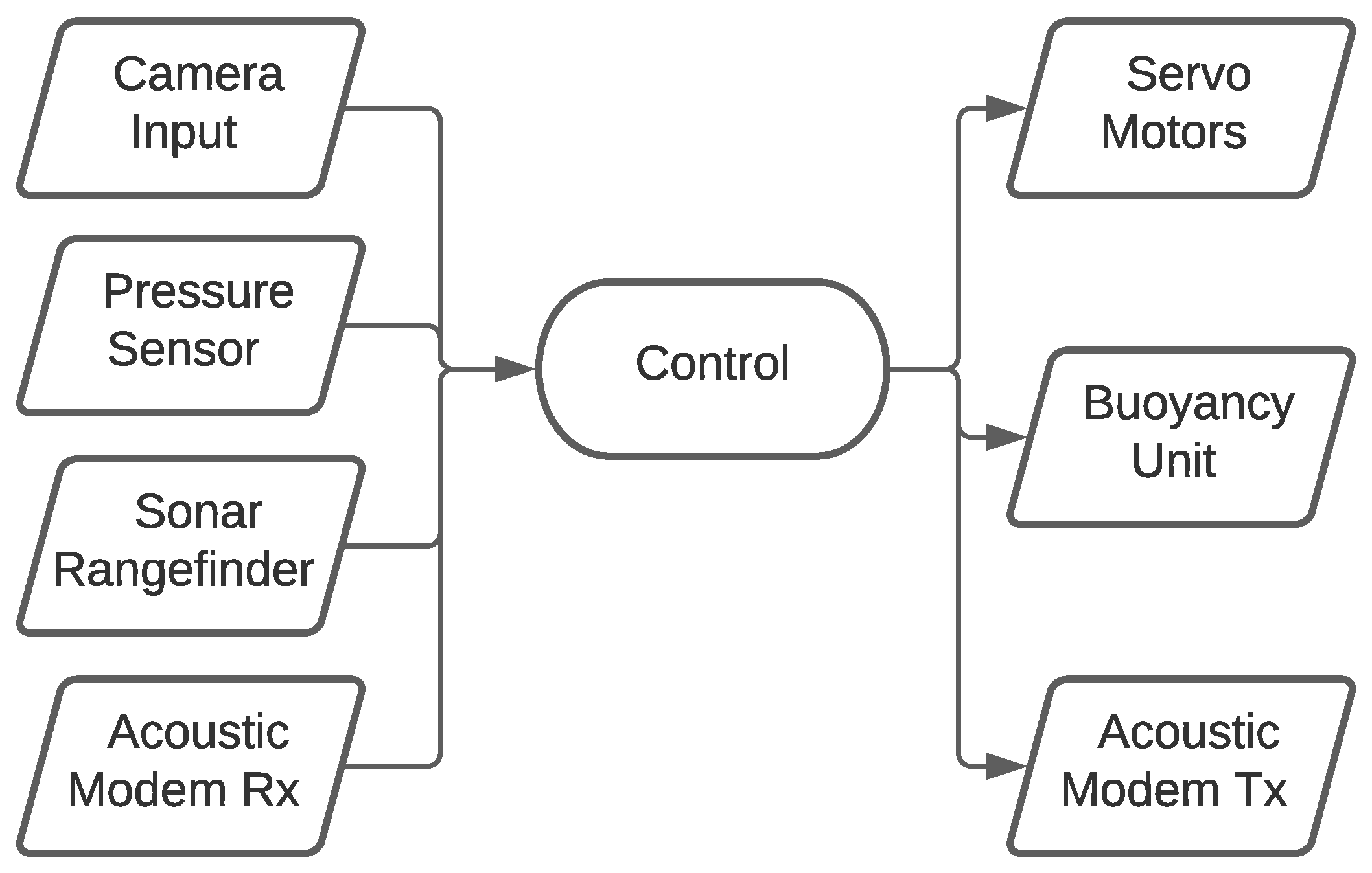
6. Locomotion Control
6.1. Conventional Control
6.2. CPG-Control
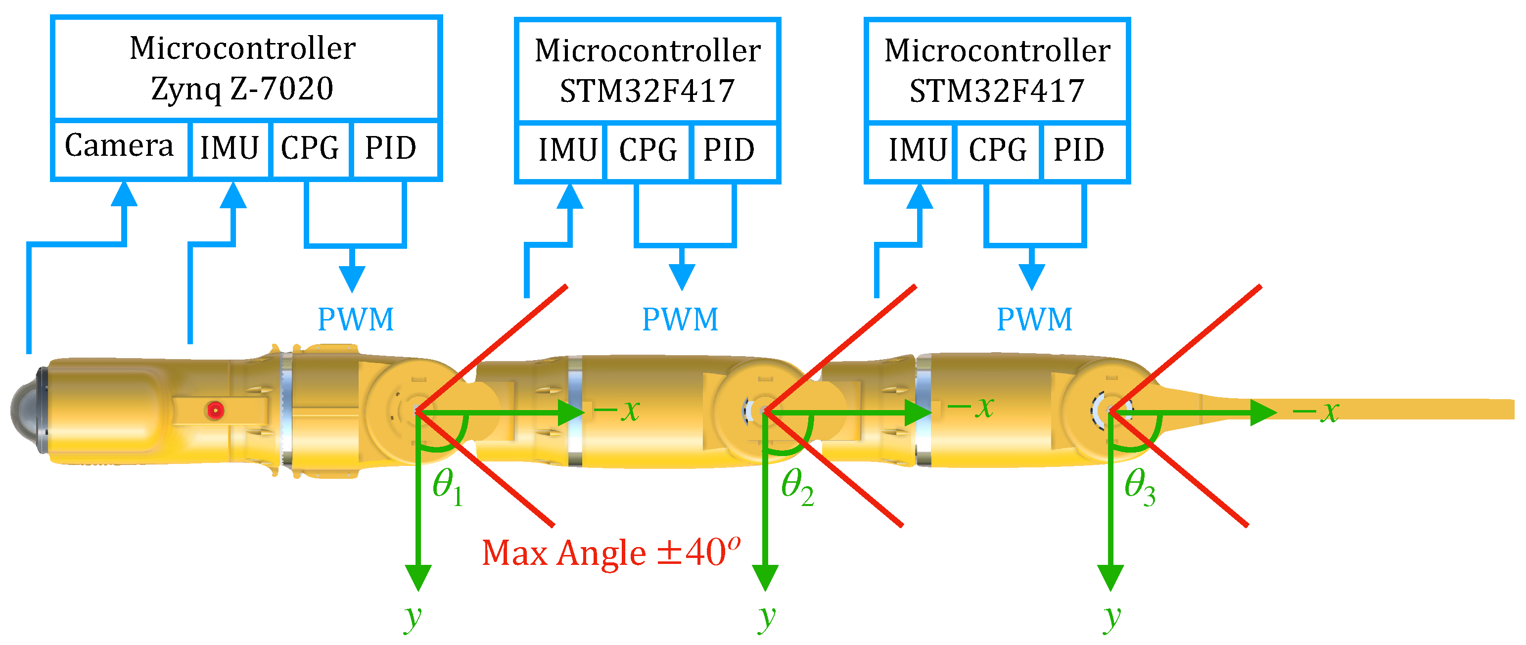
6.3. RoboFish Locomotion Control Architecture
7. Initial Testing and Lessons Learned
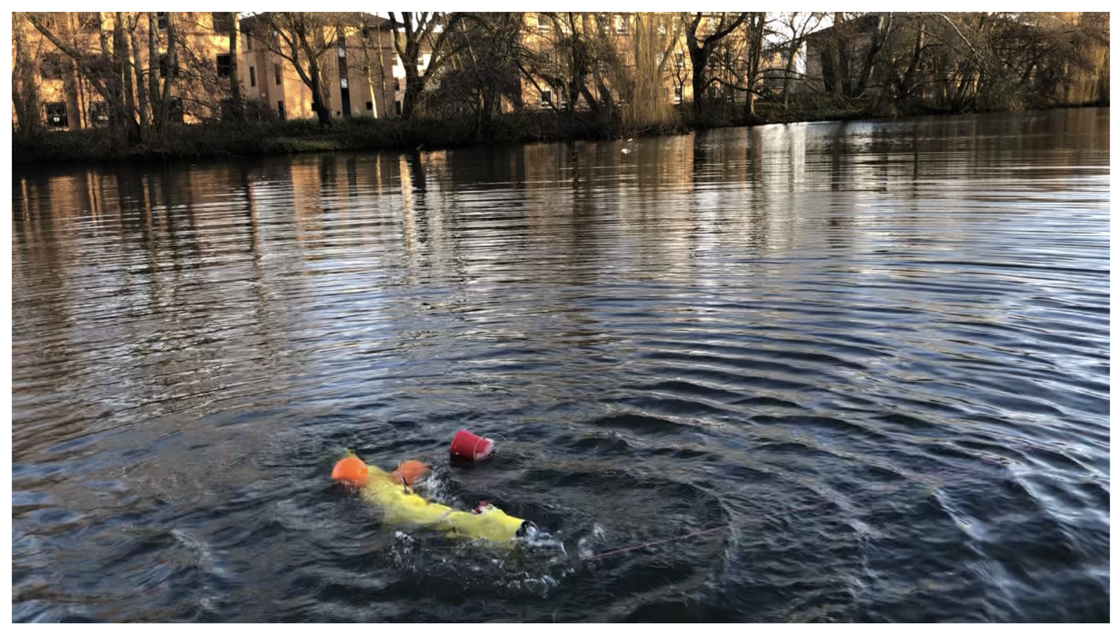
7.1. Testing Propulsion
- Testing water-tightness
- Testing the functionality of magnetic-coupling joints
- Testing propulsion
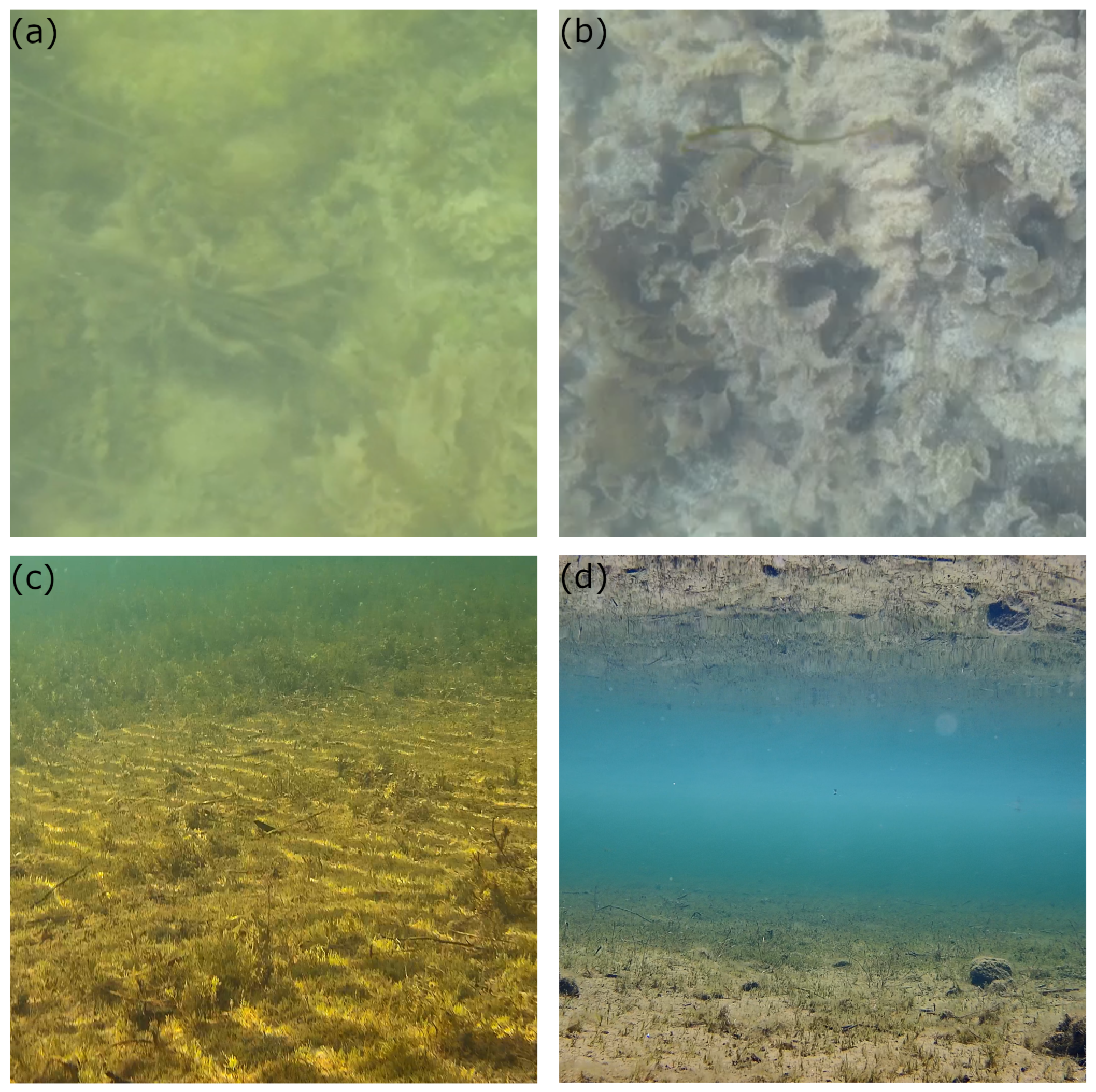
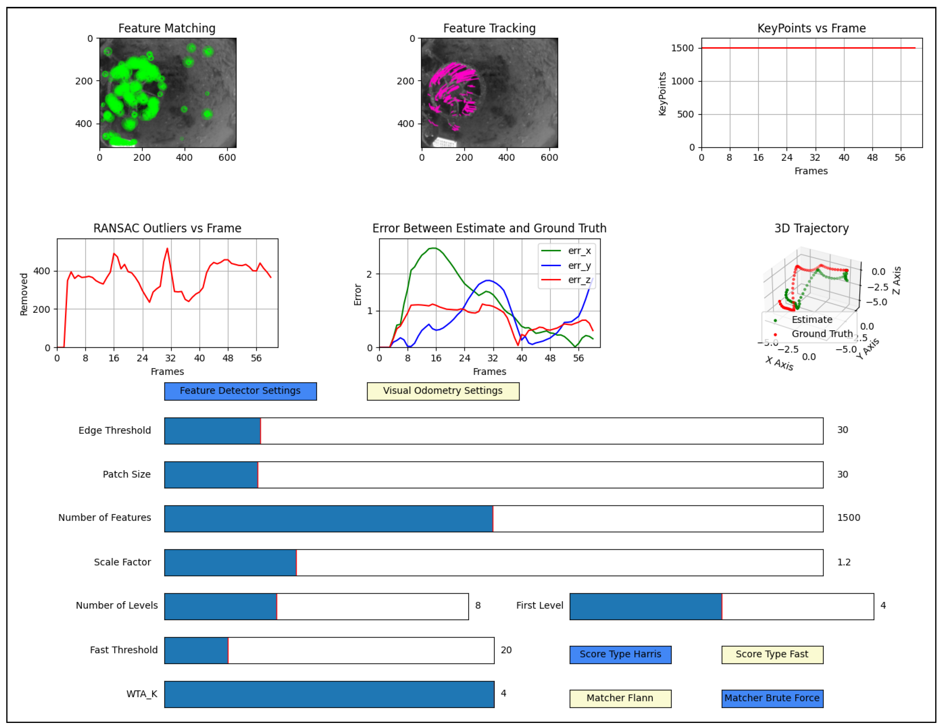
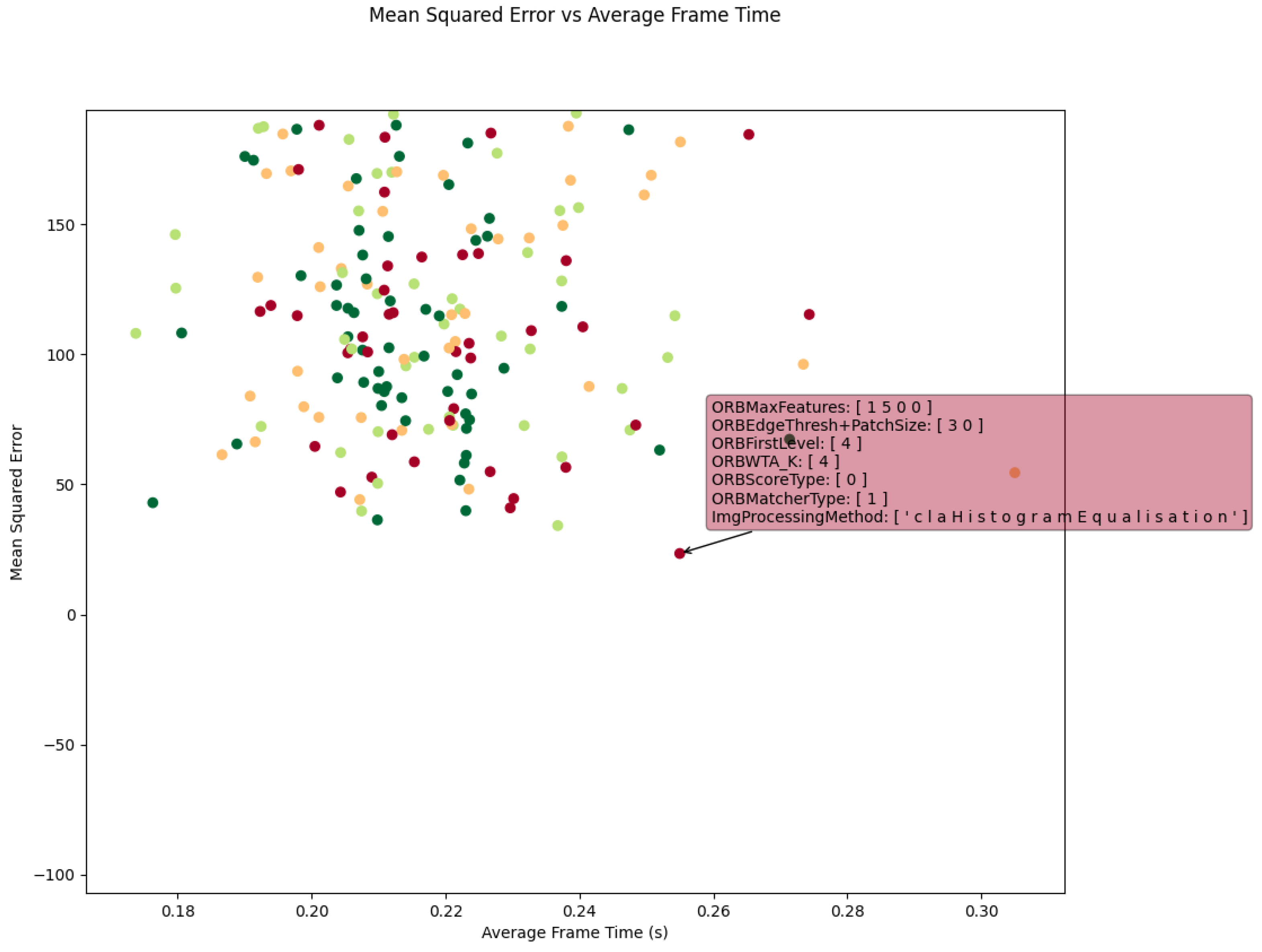
7.2. Testing Computer Vision
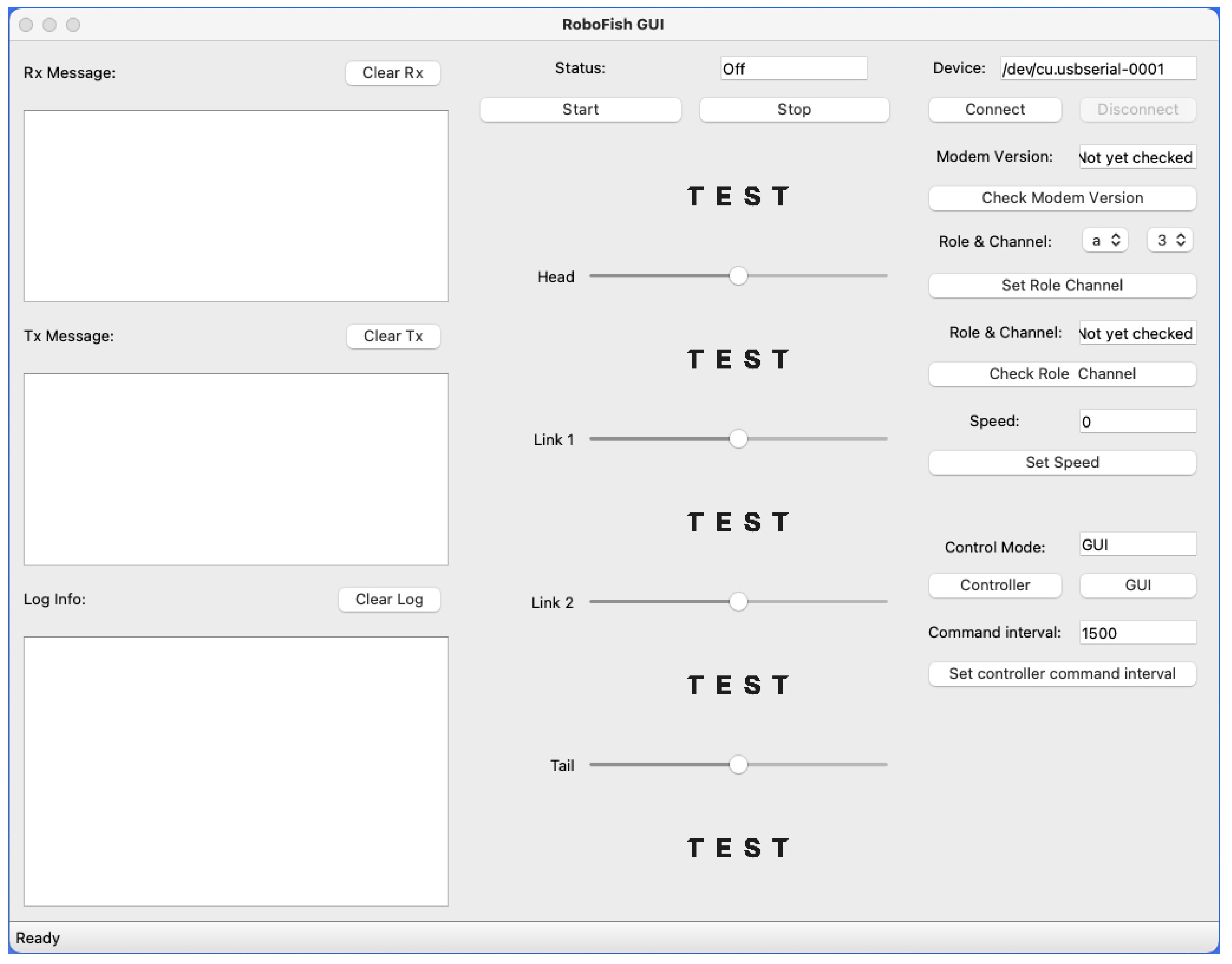
7.3. Testing Acoustic Communication and Rangefinding
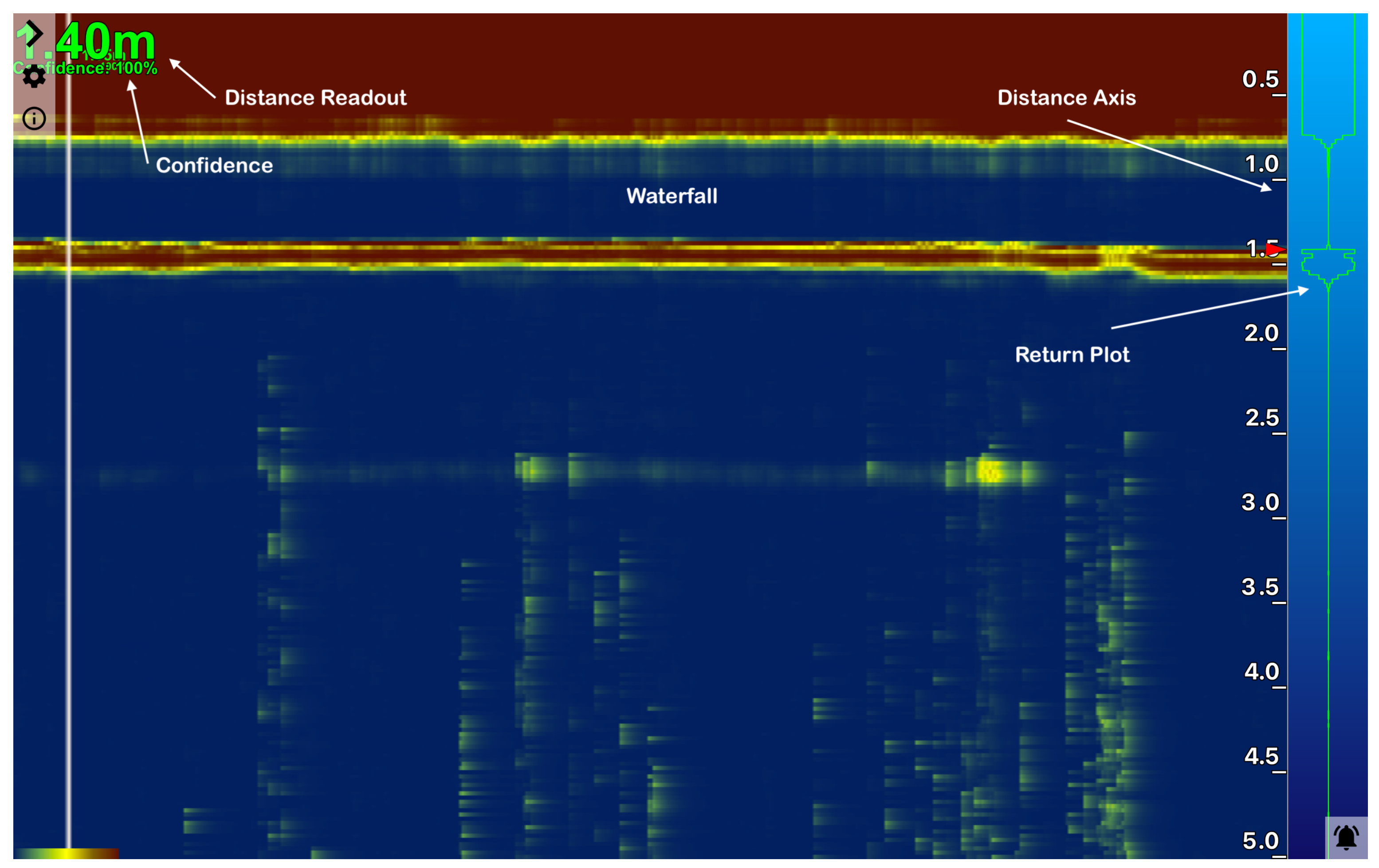
- Distance Readout: The Distance Readout presents the distance to the target in the latest measurement. The reading that is shown in Figure 19 was the distance to the floor in a testing tank during RoboFish’s initial trials. The confidence measurement for the newest range reading is presented below the distance reading and is colour-coded based on strength as follows: green = 100%, yellow = 50% and red = 0%.
- Distance Axis: This vertical axis represents the distance from the transducer built in the Echo-sounder. It starts from the top of the window, which represents zero distance from the face of the transducer and runs down vertically with the distance to the farthest object being at the bottom. Its scale automatically adjusts to indicate a live scanning range of the rangefinder.
- Return Plot: The Return Plot presents the echo strength against the distance of the newest profile sample. The stronger an echo is, the wider its trace appears.
- Waterfall: The Waterfall is a 3D trace presenting consecutive profile samples. The X axis is time; and Y axis is new distance reading shifting from right to left as a new echo arrives.
8. Future Work
9. Conclusions
Author Contributions
Funding
Institutional Review Board Statement
Informed Consent Statement
Data Availability Statement
Acknowledgments
Conflicts of Interest
Abbreviations
| AMBA | Advanced Microcontroller Bus Architecture |
| AUV | Autonomous Underwater Vehicles |
| ASA | Acrylonitrile Styrene Acrylate |
| AXI | Advanced eXtensible Interface |
| CAN | Controller Area Network |
| CFD | Computational Fluid Dynamics |
| CSI | Camera Serial Interface |
| CPG | Central pattern generators |
| FDM | Fused Deposition Modelling |
| FSI | Fluid–Structure interaction |
| FPGA | Field Programmable Gate Array |
| GPIO | General Purpose Input-Output |
| IC | Integrated Circuit |
| IMU | Inertial Measurement Unit |
| KPA | Key Performance Attributes |
| MIPI | Mobile Industry Processor Interface |
| ORE | Offshore renewable energy |
| PCB | Printed circuit board |
| PID | Proportional Integral Derivative |
| PWM | Pulse Width Modulation |
| ROV | Remotely Operated Vehicles |
| SoC | System-on-Chip |
| SoM | System-on-Module |
| SONAR | Sound Navigation and Ranging |
| SoC | System on a chip |
References
- Darwish, A.S.; Al-Dabbagh, R. Wind energy state of the art: Present and future technology advancements. Renew. Energy Environ. Sustain. 2020, 5, 7. [Google Scholar] [CrossRef]
- Liu, P.; Barlow, C.Y. Wind turbine blade waste in 2050. Waste Manag. 2017, 62, 229–240. [Google Scholar] [CrossRef]
- Pliego Marugan, A.; Garcia Marquez, F.P.; Pinar Perez, J.M. Optimal maintenance management of offshore wind farms. Energies 2016, 9, 46. [Google Scholar] [CrossRef]
- Shafiee, M.; Sørensen, J.D. Maintenance optimization and inspection planning of wind energy assets: Models, methods and strategies. Reliab. Eng. Syst. Saf. 2019, 192, 105993. [Google Scholar] [CrossRef]
- Mitchell, D.; Zaki, O.; Blanche, J.; Roe, J.; Kong, L.; Harper, S.; Robu, V.; Lim, T.; Flynn, D. Symbiotic System of Systems Design for Safe and Resilient Autonomous Robotics in Offshore Wind Farms. arXiv 2021, arXiv:2101.09491. [Google Scholar]
- Hegde, J.; Utne, I.B.; Schjølberg, I. Applicability of Current Remotely Operated Vehicle Standards and Guidelines to Autonomous Subsea IMR Operations. In Proceedings of the International Conference on Offshore Mechanics and Arctic Engineering, St. John’s, NL, Canada, 31 May–5 June 2015; pp. 1–10. [Google Scholar]
- Scaradozzi, D.; Palmieri, G.; Costa, D.; Pinelli, A. BCF swimming locomotion for autonomous underwater robots: A review and a novel solution to improve control and efficiency. Ocean. Eng. 2017, 130, 437–453. [Google Scholar] [CrossRef]
- Sfakiotakis, M.; Lane, D.M.; Davies, J.B.C. Review of fish swimming modes for aquatic locomotion. IEEE J. Ocean. Eng. 1999, 24, 237–252. [Google Scholar] [CrossRef]
- Fish, F.E. Advantages of aquatic animals as models for bio-inspired drones over present AUV technology. Bioinspiration Biomim. 2020, 15, 025001. [Google Scholar] [CrossRef] [PubMed]
- Blake, R. Fish functional design and swimming performance. J. Fish Biol. 2004, 65, 1193–1222. [Google Scholar] [CrossRef]
- Triantafyllou, M.S.; Triantafyllou, G.S. An efficient swimming machine. Sci. Am. 1995, 272, 64–70. [Google Scholar] [CrossRef]
- Tytell, E.D. The hydrodynamics of eel swimming II. Effect of swimming speed. J. Exp. Biol. 2004, 207, 3265–3279. [Google Scholar] [CrossRef]
- Weihs, D. Stability versus maneuverability in aquatic locomotion. Integr. Comp. Biol. 2002, 42, 127–134. [Google Scholar] [CrossRef] [PubMed]
- Christ, R.D.; Wernli, S.R.L. The ROV Manual: A User Guide for Observation Class Remotely Operated Vehicles; Elsevier: Amsterdam, The Netherlands, 2011. [Google Scholar]
- Macreadie, P.I.; McLean, D.L.; Thomson, P.G.; Partridge, J.C.; Jones, D.O.; Gates, A.R.; Benfield, M.C.; Collin, S.P.; Booth, D.J.; Smith, L.L.; et al. Eyes in the sea: Unlocking the mysteries of the ocean using industrial, remotely operated vehicles (ROVs). Sci. Total. Environ. 2018, 634, 1077–1091. [Google Scholar] [CrossRef]
- Owens, D. Rex 2: Design, Construction, and Operation of an Unmanned Underwater Vehicle. Master’s Thesis, Massachusetts Institute of Technology, Cambridge, MA, USA, 2009. [Google Scholar]
- Brege, E.D. Design and Construction of a Low Cost, Modular Autonomous Underwater Vehicle. Engineer’s Thesis, Massachusetts Institute of Technology, Cambridge, MA, USA, 2011. [Google Scholar]
- Furlong, M.E.; Paxton, D.; Stevenson, P.; Pebody, M.; McPhail, S.D.; Perrett, J. Autosub Long Range: A long range deep diving AUV for ocean monitoring. In Proceedings of the 2012 IEEE/OES Autonomous Underwater Vehicles (AUV), Southampton, UK, 24–27 September 2012; pp. 1–7. [Google Scholar]
- Marthiniussen, R.; Vestgard, K.; Klepaker, R.; Storkersen, N. HUGIN-AUV concept and operational experiences to date. In Proceedings of the Oceans ‘04 MTS/IEEE Techno-Ocean ’04 (IEEE Cat. No.04CH37600), Kobe, Japan, 9–12 November 2004; Volume 2, pp. 846–850. [Google Scholar]
- Liljebäck, P.; Mills, R. Eelume: A flexible and subsea resident IMR vehicle. In Proceedings of the OCEANS 2017—Aberdeen, Aberdeen, UK, 19–22 June 2017; pp. 1–4. [Google Scholar]
- Raj, A.; Thakur, A. Fish-inspired robots: Design, sensing, actuation, and autonomy—A review of research. Bioinspir. Biomim. 2016, 11, 031001. [Google Scholar] [CrossRef]
- Kruusmaa, M.; Toming, G.; Salumäe, T.; Ježov, J.; Ernits, A. Swimming speed control and on-board flow sensing of an artificial trout. In Proceedings of the 2011 IEEE International Conference on Robotics and Automation, Shanghai, China, 9–13 May 2011; pp. 1791–1796. [Google Scholar]
- Kelasidi, E.; Liljebäck, P.; Pettersen, K.Y.; Gravdahl, J.T. Experimental investigation of efficient locomotion of underwater snake robots for lateral undulation and eel-like motion patterns. Robot. Biomim. 2015, 2, 1–27. [Google Scholar] [CrossRef]
- Bayat, B.; Crespi, A.; Ijspeert, A. Envirobot: A bio-inspired environmental monitoring platform. In Proceedings of the 2016 IEEE/OES Autonomous Underwater Vehicles (AUV), Tokyo, Japan, 6–9 November 2016; pp. 381–386. [Google Scholar] [CrossRef]
- Yamada, H.; Chigisaki, S.; Mori, M.; Takita, K.; Ogami, K.; Hirose, S. Development of Amphibious Snake-like Robot ACM-R5. In Proceedings of the International Federation of Robotics International Symposium on Robotics, Tokyo, Japan, 29 November–1 December 2005; p. 133. [Google Scholar]
- Fierstine, H.L.; Walters, V. Studies in locomotion and anatomy of scombroid fishes. South Calif. Acad. Sci. 1968, 1–31. [Google Scholar]
- Luo, Y.; Xiao, Q.; Shi, G.; Pan, G.; Chen, D. The effect of variable stiffness of tuna-like fish body and fin on swimming performance. Bioinspir. Biomim. 2020, 16, 016003. [Google Scholar] [CrossRef] [PubMed]
- Luo, Y.; Xiao, Q.; Shi, G.; Wen, L.; Chen, D.; Pan, G. A fluid—Structure interaction solver for the study on a passively deformed fish fin with non-uniformly distributed stiffness. J. Fluids Struct. 2020, 92, 102778. [Google Scholar] [CrossRef]
- Wright, M.; Luo, Y.; Xiao, Q.; Post, M.; Gorma, W.; Durrant, A.; Yue, H. CFD-FSI Analysis on Motion Control of Bio-Inspired Underwater AUV System Utilizing PID Control. In Proceedings of the 2020 IEEE/OES Autonomous Underwater Vehicles Symposium (AUV), St. John’s, NL, Canada, 30 September–2 October 2020; pp. 1–6. [Google Scholar]
- Wright, M.; Gorma, W.; Luo, Y.; Post, M.; Xiao, Q.; Durrant, A. Multi-actuated AUV Body for Windfarm Inspection: Lessons from the Bio-inspired RoboFish Field Trials. In Proceedings of the 2020 IEEE/OES Autonomous Underwater Vehicles Symposium (AUV), St. John’s, NL, Canada, 30 September–2 October 2020; pp. 1–6. [Google Scholar]
- Mur-Artal, R.; Tardos, J.D. ORB-SLAM2: An Open-Source SLAM System for Monocular, Stereo and RGB-D Cameras. IEEE Trans. Robot. 2016, 33, 1255–1262. [Google Scholar] [CrossRef]
- Shang, Z.; Shen, Z. Real-time 3D Reconstruction on Construction Site using Visual SLAM and UAV. arXiv 2017, arXiv:1712.07122. [Google Scholar]
- Ferreira, F.; Veruggio, G.; Caccia, M.; Bruzzone, G. Real time optical SLAM based mosaickingfor unmanned underwater vehicles. Intell. Serv. Robot. 2012, 5, 55–71. [Google Scholar] [CrossRef]
- Akkaynak, D.; Treibitz, T. Sea-thru: A method for removing water from underwater images. In Proceedings of the IEEE/CVF Conference on Computer Vision and Pattern Recognition, Long Beach, CA, USA, 15–20 June 2019; pp. 1682–1691. [Google Scholar]
- Köser, K.; Frese, U. Challenges in Underwater Visual Navigation and SLAM. In AI Technology for Underwater Robots; Intelligent Systems, Control and Automation: Science and Engineering; Springer International Publishing: Cham, Switzerland, 2019; pp. 125–135. [Google Scholar]
- Culjak, I.; Abram, D.; Pribanic, T.; Dzapo, H.; Cifrek, M. A brief introduction to OpenCV. In Proceedings of the 35th International Convention MIPRO, Opatija, Croatia, 21–25 May 2012; pp. 1725–1730. [Google Scholar]
- Rublee, E.; Rabaud, V.; Konolige, K.; Bradski, G. ORB: An Efficient Alternative to SIFT or SURF. In Proceedings of the 2011 International Conference on Computer Vision, Barcelona, Spain, 6–13 November 2011; pp. 2564–2571. [Google Scholar]
- Leutenegger, S.; Chli, M.; Siegwart, R.Y. BRISK: Binary Robust Invariant Scalable Keypoints. In Proceedings of the 2011 International Conference on Computer Vision, Barcelona, Spain, 6–13 November 2011; pp. 2548–2555. [Google Scholar]
- Lowe, D.G. Distinctive image features from scale-invariant keypoints. Int. J. Comput. Vis. 2004, 60, 91–110. [Google Scholar] [CrossRef]
- Bay, H.; Tuytelaars, T.; Van Gool, L. SURF: Speeded Up Robust Features. In Computer Vision—ECCV 2006; Springer: Berlin/Heidelberg, Germany, 2006; pp. 404–417. [Google Scholar]
- Freda, L. PySLAM. Github. Available online: https://github.com/luigifreda/pyslam (accessed on 10 February 2020).
- Ferrera, M.; Creuze, V.; Moras, J.; Trouvé-Peloux, P. AQUALOC: An Underwater Dataset for Visual-Inertial-Pressure Localization. Int. J. Robot. Res. 2019, 38, 1549–1559. [Google Scholar] [CrossRef]
- BlueRobotics Water Linked M64 Acoustic Modem. Available online: https://bluerobotics.com/store/comm-control-power/acoustic-modems/wl-11003-1/ (accessed on 25 April 2021).
- Water Linked, Modem-M64 Serial Protocol. Available online: https://waterlinked.github.io/modems/modem-m64-protocol/ (accessed on 25 April 2021).
- BlueRobotics Ping Sonar Altimeter and Echosounder. Available online: https://bluerobotics.com/store/sensors-sonars-cameras/sonar/ping-sonar-r2-rp/ (accessed on 25 April 2021).
- Mathieu Porez, F.B.; Ijspeer, A.J. Improved Lighthill fish swimming model for bio-inspired robots: Modeling, computational aspects and experimental comparisons. Int. J. Robot. Res. 2014, 33, 1322–1341. [Google Scholar] [CrossRef]
- Graver, J.G.; Leonard, N.E. Underwater Glider Dynamics and Control. In Proceedings of the 12th International Symposium on Unmanned Untethered Submersible Technology, Durham, NH, USA, 27 August 2001; pp. 1710–1742. [Google Scholar]
- Slotine, J.J.E.; Karl Herdick, J. Robust input-output feedback linearization. Int. J. Control. 1993, 57, 1133–1139. [Google Scholar] [CrossRef]
- Lillicrap, T.P.; Hunt, J.J.; Pritzel, A.; Heess, N.; Erez, T.; Tassa, Y.; Silver, D.; Wierstra, D. Continuous Control with Deep Reinforcement Learning. arXiv 2015, arXiv:1509.02971. [Google Scholar]
- Argentim, L.M.; Rezende, W.C.; Santos, P.E.; Aguiar, R.A. PID, LQR and LQR-PID on a Quadcopter Platform. In Proceedings of the 2013 International Conference on Informatics, Electronics and Vision (ICIEV), Dhaka, Bangladesh, 17–18 May 2013; pp. 1–6. [Google Scholar]
- Yoo, J.; Jang, D.; Kim, H.J.; Johansson, K.H. Hybrid reinforcement learning control for a micro quadrotor flight. IEEE Control. Syst. Lett. 2020, 5, 505–510. [Google Scholar] [CrossRef]
- Fernandez, G.I.; Togashi, C.; Hong, D.; Yang, L. Deep Reinforcement Learning with Linear Quadratic Regulator Regions. arXiv 2020, arXiv:2002.09820. [Google Scholar]
- Jo, N.H.; Shim, H.; Son, Y.I. Disturbance observer for non-minimum phase linear systems. Int. J. Control. Autom. Syst. 2010, 8, 994–1002. [Google Scholar] [CrossRef]
- Kim, J.; Bates, D.G.; Postlethwaite, I. Robustness analysis of linear periodic time-varying systems subject to structured uncertainty. Syst. Control. Lett. 2006, 55, 719–725. [Google Scholar] [CrossRef]
- Melsaac, K.; Ostrowski, J. A Geometric Approach to Anguilliform Locomotion: Modelling of an Underwater Eel Robot. In Proceedings of the 1999 IEEE International Conference on Robotics and Automation, Detroit, MI, USA, 10–15 May 1999; Volume 4, pp. 2843–2848. [Google Scholar]
- Yu, J.; Tan, M.; Chen, J.; Zhang, J. A survey on CPG-inspried control mdels and system implementation. IEEE Trans. Neural Netw. Learn. Syst. 2014, 25, 441–455. [Google Scholar] [CrossRef] [PubMed]
- Crespi, A.; Lachat, D.; Pasquier, A.; Ijspeert, A. Controlling swimming and crawling in a fish robot using a central pattern generator. Auton. Robot. 2008, 25, 3–13. [Google Scholar] [CrossRef]
- Oleari, F.; Kallasi, F.; Rizzini, D.L.; Aleotti, J.; Caselli, S. An Underwater Stereo Vision System: From Design to Deployment and Dataset Acquisition. In Proceedings of the OCEANS 2015, Genova, Italy, 18–21 May 2015; pp. 1–6. [Google Scholar]
- BlueRobotics BLUART USB to TTL Serial and RS485 Adapter. Available online: https://bluerobotics.com/store/comm-control-power/tether-interface/bluart-r1-rp/ (accessed on 25 April 2021).


| Attribute | Objective |
|---|---|
| Depth [m] | 100 |
| Mission Duration [hrs] | 3 |
| Weight [kg] | 30 |
| Length [m] | 1.9 |
| Duty Cycle [%] | 75 |
| Modular | Yes |
| Speed [knot] | 0.5 |
| Parameter | Value | Comment |
|---|---|---|
| Layer height | 0.254 mm | Standard |
| extrusion width | 0.5 mm | Standard |
| Wall thickness | 2.032 mm | To print more perimeters per layer |
| Solid infill | Enabled | To help preventing water ingress |
| Variable width fill | Enabled | To fill any small gaps |
| Room temperature | Enclosure |
Publisher’s Note: MDPI stays neutral with regard to jurisdictional claims in published maps and institutional affiliations. |
© 2021 by the authors. Licensee MDPI, Basel, Switzerland. This article is an open access article distributed under the terms and conditions of the Creative Commons Attribution (CC BY) license (https://creativecommons.org/licenses/by/4.0/).
Share and Cite
Gorma, W.; Post, M.A.; White, J.; Gardner, J.; Luo, Y.; Kim, J.; Mitchell, P.D.; Morozs, N.; Wright, M.; Xiao, Q. Development of Modular Bio-Inspired Autonomous Underwater Vehicle for Close Subsea Asset Inspection. Appl. Sci. 2021, 11, 5401. https://doi.org/10.3390/app11125401
Gorma W, Post MA, White J, Gardner J, Luo Y, Kim J, Mitchell PD, Morozs N, Wright M, Xiao Q. Development of Modular Bio-Inspired Autonomous Underwater Vehicle for Close Subsea Asset Inspection. Applied Sciences. 2021; 11(12):5401. https://doi.org/10.3390/app11125401
Chicago/Turabian StyleGorma, Wael, Mark A. Post, James White, James Gardner, Yang Luo, Jongrae Kim, Paul D. Mitchell, Nils Morozs, Marvin Wright, and Qing Xiao. 2021. "Development of Modular Bio-Inspired Autonomous Underwater Vehicle for Close Subsea Asset Inspection" Applied Sciences 11, no. 12: 5401. https://doi.org/10.3390/app11125401
APA StyleGorma, W., Post, M. A., White, J., Gardner, J., Luo, Y., Kim, J., Mitchell, P. D., Morozs, N., Wright, M., & Xiao, Q. (2021). Development of Modular Bio-Inspired Autonomous Underwater Vehicle for Close Subsea Asset Inspection. Applied Sciences, 11(12), 5401. https://doi.org/10.3390/app11125401