1. Introduction
Electronic cigarettes (e-cigs) have been on the market for more than ten years. They have the same elements (
Figure 1): an atomiser screwed or welded to a power unit. Atomisers are metallic cylinders with a coil unit that are sold empty. They are filled by a user with an e-liquid. In their design, the air inflow and aerosol outflow allow air circulation during the inhalation. The coil unit is also a metallic cylinder containing a resistive wire and a porous media draining the e-liquid from the tank (initial empty volume that is designed to receive and to stock the e-liquid) to the wire.
In the beginning, they had the same design as classical cigarettes. They were mostly made as a closed unit. The power unit used to deliver a fixed power was sealed to the rest of the device. Then, power units began to be screw-off and rechargeable. Following this innovation, adjustable power units appeared in the market. The power regulation had paved the way for the development of a wide panel of atomisers and e-liquids. More than 33,000 e-liquids and 6000 electronic cigarettes and accessories have been declared between 2017 and 2020 to the French Agency for Food, Environmental and Occupational Health & Safety (ANSES) [
1].
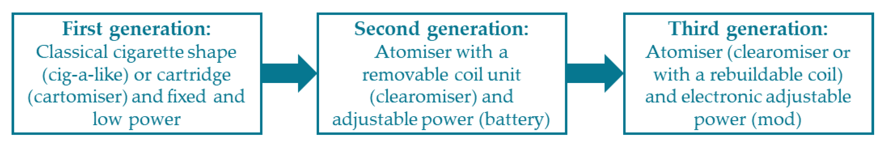
E-cigs are commonly classified by the generation of products mostly based on designed characteristics. Many descriptions are available but there are not standardized characteristics that allow an objective classification. In a publication, authors reviewed the current classifications available on the web [
2] describing each category of products (
Figure 2).
This classification mainly describes a story about the development of the devices since their apparition. Through this classification, there is not clear criteria allowing a strict classification of a device in a group.
Despite this wide market, the electronic cigarette function has not changed. As the user activates the power unit, an electrical current is delivered to the resistive wire. In response, the wire heats and vaporizes the surrounding e-liquid. The generated aerosol is finally inhaled by a consumer. So, e-cigs are devices using a thermal and thermodynamic phenomenon to generate an aerosol and depending on the e-liquid composition to deliver an active molecule such as nicotine. The variety of vaping products available (e-cigs and e-liquids) offers a large panel of configurations for a consumer.
The electronic cigarette functioning using standardized conditions was recently characterized [
3]. According to the supplied power, three vaporization regimens were identified and described. At low powers, no aerosol is generated. This vaporization regimen is called under-heating. Increasing the power leads to the optimal regimen. In this one, the mass of vaporized e-liquid (MVE) according to the supplied power shows a linear trend. Then, above a power limit, this linearity is broken, and an over-heating regimen is reached. Consequently, the optimal regimen was characterized by two power limits: minimal and maximal powers.
In a recent publication [
4], authors link these regimens to the produced aldehydes and highlight a significant increase in their productions using powers higher than the maximal power. They also suggest a link between the boiling process and vaping. The maximal limit would correspond to the critical heat flux. Consequently, wire surface is a key parameter that defines the limits of the optimal vaping regimen. By extension, knowing its value allow the determination of these limits and a requirement of power range with a lower chemical risk.
Additionally, we showed how vaping regimen (airflow rate) influenced the optimal vaporisation regimen [
5]. The inhalation through an e-cig is commonly separated into two main behaviours (
Figure 3): a mouth to lungs (MTL) or a direct lung (DL) inhalation. As illustrated, using MTL vaping regimen [
6] reduces significantly the optimal vaporisation limits (lower minimal and maximal powers) and devices efficiencies. So, the power ranges required by a manufacturer of a sub-ohm devices would partially or totally be in an overheating regimen. It would present a more important chemical risk for the user. Consequently, understanding the technical characteristics relative of MTL or DL group of devices will improve their requirements under reduced risks for users. Additionally, we suggested the needed to define a standardized direct lung vaping regimen. It should be supported by technical requirements. Current classification does not allow an objective definition of these requirements. An aim of this publication is to provide these requirements.
These two behaviours are identifiable through the respiratory organ filled by the generated aerosol. In MTL, users filled their mouth with the aerosol, stop vaping, and take a deeper inhalation in order to move the aerosol into the lungs. In DL, there is no stop, and the aerosol is directly moved into the lungs.
Additionally, in the inhalation mechanism, the inhalable or exhalable volumes by a human are linked to the pressure applied by the respiratory system. A typical pressure-volume diagram for a static human is presented in
Figure 4. At a low pressure, lungs could be filled with air. However, they present a pressure limit below which the lung’s capacities are close to zero. When a user inhales through a device, it generates a necessary pressure drop that decreases lung capacity.
A value of 10 kPa is medically accepted as a physical limit [
8] below which a human could not inhale. Consequently, the pressure drop generated by a device is an important parameter in the understanding of inhalation behaviour. The parameter linking the pressure drop generated and airflow rate is called air resistance. It should also be a key characteristic that will modulate the inhalation and by implication the heat exchange with the wire.
This publication aims to provide a classification inspired from heat exchanger analyses [
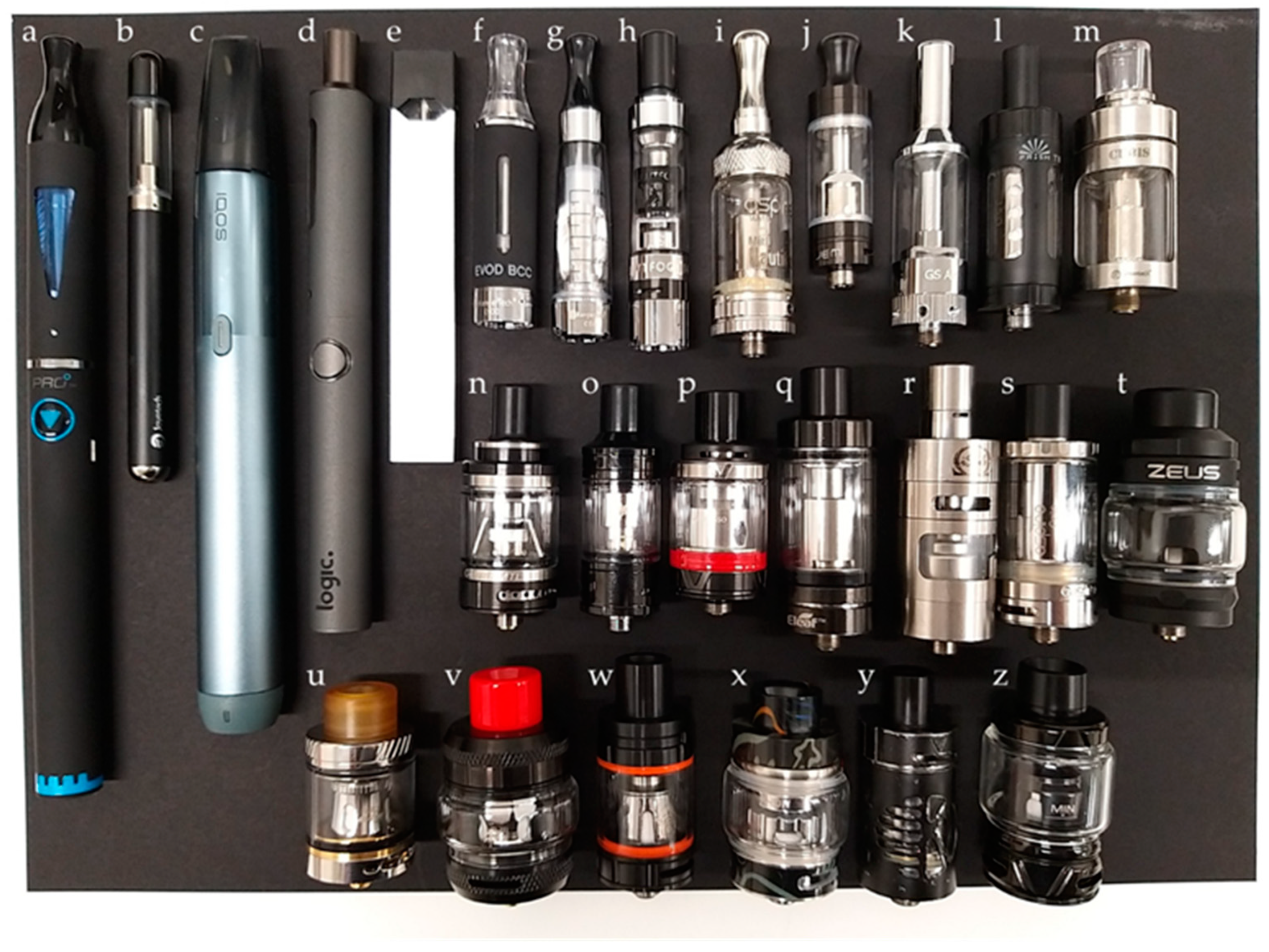
9,
10] and to provide the technical criteria between MTL and DL requirements and between standardized and direct lungs vaping regimens use. Twenty-six devices are characterized. As the wire surface is the most central property, it is consequently the first series of experiments carried. The second series of experiments aimed to determine the air resistance generated by each device.
3. Results
Results are presented following a list of parameters, the first of which is the recommended powers (fixed power or power ranges).
3.1. Power Ranges Analysis
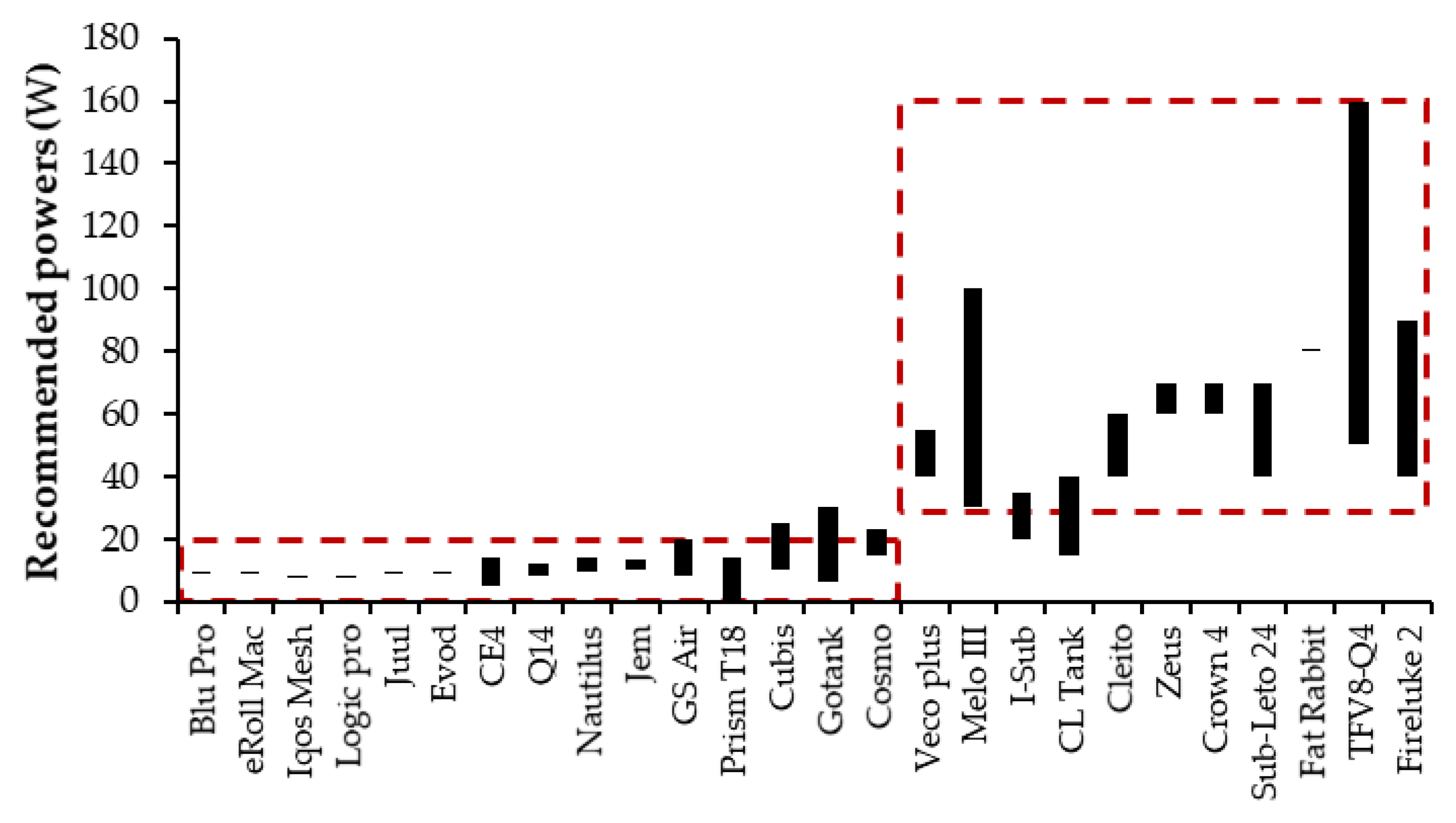
Figure 8 illustrates the recommended powers of the twenty-six e-cigs and atomisers.
Two main groups of devices emerge:
a low power group with recommended powers below 20 W regrouping most of the fixed power e-cigs.
a high-power group with recommended powers above 30 W. This second group could be used at higher powers and on a larger power range than devices of the first group.
However, some devices are recommended for powers mainly in one group and are able to go beyond these limits, such as Cubis, Gotank and Cosmo for the first group and I-Sub and CL Tank for the second one. Analysing more devices would allow a more precise determination between these two groups. Based on these devices, an average limit of 25 W will be used as a power limit. These two identified groups are systematically highlighted in the results in order to observe if they are identifiable with the mechanical characteristics.
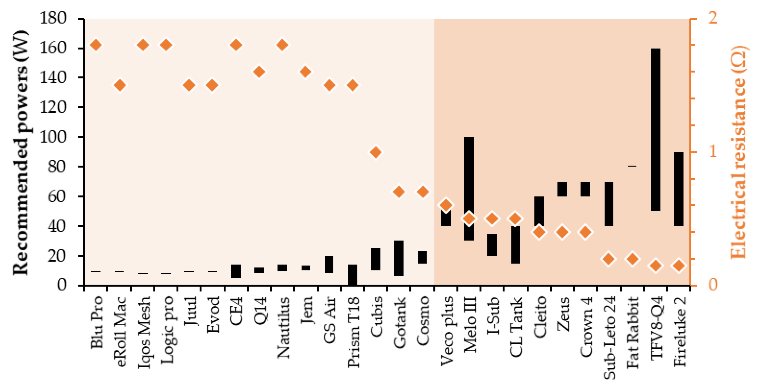
3.2. Electrical Resistance Analysis
Figure 9 provides a graphical representation of the recommended powers and the electrical resistance for each device.
The two groups are also identifiable, but the limit is not between Cosmo and Veco plus but rather between Prism T18 and Cubis. From Blu Pro and Prism T18, e-cigs are designed for low powers with an electrical resistance higher than 1.5 Ω. Cubis looks to be an intermediate between the two groups. From the Gotank, devices are designed for higher powers with electrical resistance below 0.7 Ω. A limit between these two groups is 1.1 Ω.
3.3. Wire Surface
The dimensions (diameter and length) measured for the twenty-six devices and their calculated surfaces according to Equation (1) are reported in
Table 5. However, Iqos mesh is not easily extractable without destroying its structure. Its dimensions could not be obtained correctly and are not provided. Zeus also has a mesh design, but the blades have a rectangular section.
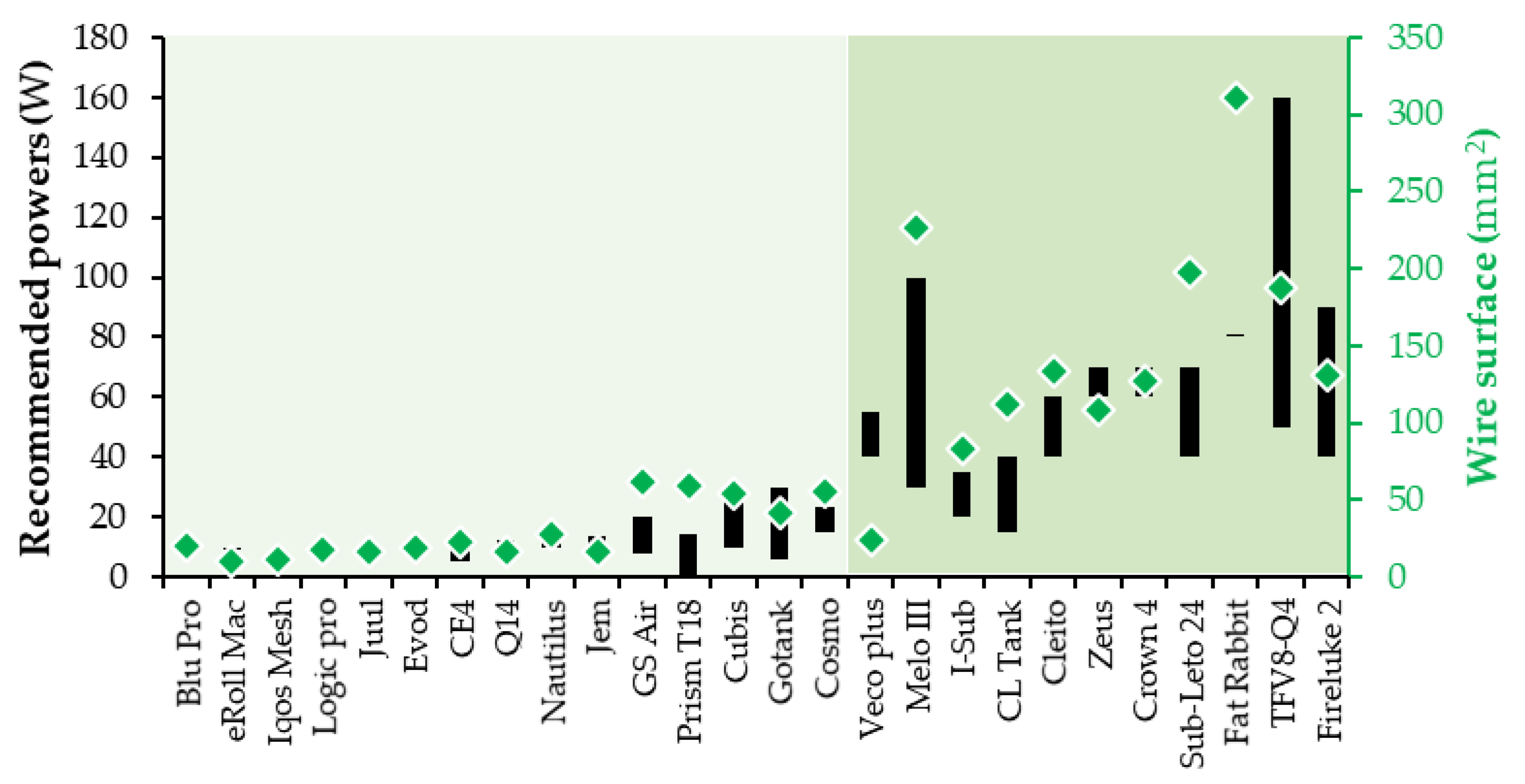
Wire diameters are lower than 0.20 mm for devices with electrical resistance upper of 1.5 Ω. Therefore, mesh devices that have electrical resistance below 0.5 Ω, also present wires with thin diameters, but the lengths are longer than previous wires. Due to their design, meshes have significantly higher surfaces. The wire surfaces are graphically represented in
Figure 10 in regard to the recommended powers.
The wire surface have a wide range of values (between 10 and 350 mm
2). Therefore, fifteen surfaces are between 10 and 62 mm
2 with nine values between 10 and 27 mm
2. In the other side, ten ones are upper than 80 mm
2 and are more dispersed. An average surface limit between 62 and 80 mm
2 is 71 mm
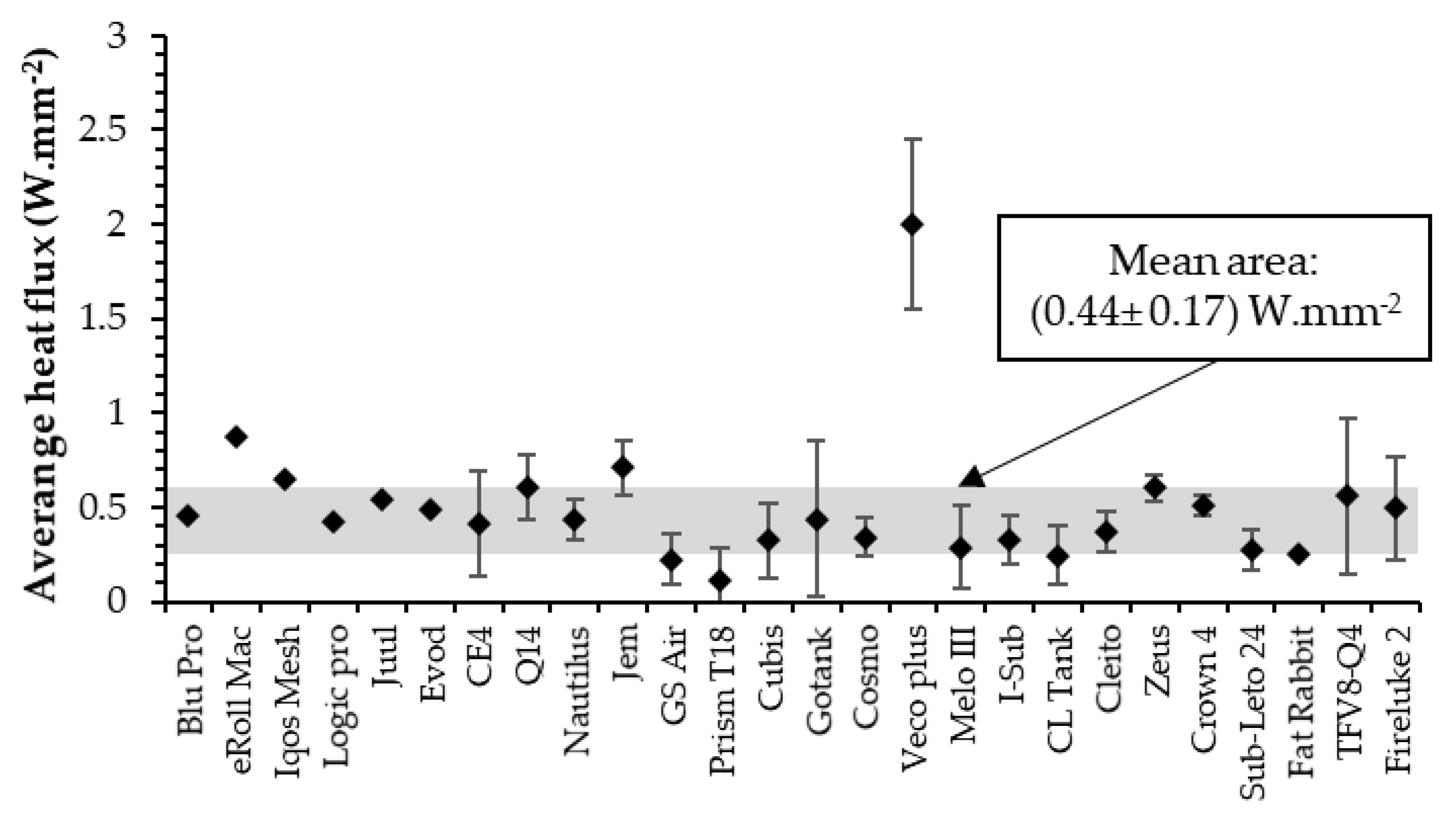
2. Additionally, wire surface and recommended powers looks correlated. In thermal problem, heat flux expresses the ratio between a power and the heat surface and characterizes the heat transfers. Following this observation,
Figure 11 shows the average heat flux determined using the average recommended power and the heat flux range represented as a deviation.
Except for the Veco plus, the average heat flux presents an interesting dispersion that is around (0.44 ± 0.17) W mm−2. This might represents a pleasant limit of the generated aerosol. Veco plus is a device with a notable element of design that is not present in the others: its wire is melded into a ceramic element. Its complete immersion might allow a higher heat flux comparing with partially immerged wire.
3.4. Air Resistance
Figure 12 illustrates the pressure drop measured according to the airflow rate applied. The respiratory limit induced by the lungs is added as a red line. The calibration curve is also added as a green line.
Graphically, each device has a parabolic profile due to the pressure drop square root (Equation (3)), then verified with the R-square (0.9904–0.9996) when air resistances are extracted. Two groups are clearly identifiable. The first one reaches the respiratory limit for airflow rate between 2 and 11 L min
−1 and curves are dispersed. The second group have low-pressure drops and do not exceed 2000 Pa at 10 L min
−1 with a small variability. Their curves look to be overlapped and are hardly separately observable. Finally, the air resistances are determined. They are subtracted by the empty setup air resistance (obtained by the calibration).
Figure 13 illustrated the treated air resistance.
The air resistance values have a wide range of values (between 0.15 and 33 Pa0.5 min L−1). Therefore, eleven values are below 2.5 Pa0.5 min L−1 with one value upper than 1.2 Pa0.5 min L−1.and seven values below 0.3 Pa0.5 min L−1. In the other side, fifteen values are upper than 7 Pa0.5 min L−1 with five values upper than 25 Pa0.5 min L−1, five between 11 and 18 Pa0.5 min L−1 and five between 7 and 9 Pa0.5 min L−1. The two groups are clearly observable and an air resistance of 4.8 Pa0.5 min L−1 could be used as a limit between them.
4. Discussion
Through this publication, we develop a classification based on mechanical characteristics: recommended powers, electrical resistance, wire surface and air resistance of an atomiser. We explain how these two groups of devices are linked to the inhalation behaviours. In reality, this illustrates how manufacturers probably developed devices: regarding the inhalation behaviour. Therefore, this new classification is not based on “what this device looks like?” but for “who these devices are intended for?”.
Additionally, results show that inhaling with a DL behaviour through a device with a high air resistance (first group) is physically impossible. In the other side, a user has to restrict significantly his inhalation in order to practice MTL with atomisers having low air resistance (second group). This would lead to discomfort during vaping. This also illustrates how the respiratory limits influence the design of the devices. Furthermore, we highlight an average heat flux (0.43 ± 0.17 W mm
−2) that looks to be a constant of devices (excepted for Veco plus). In a recent publication [
4], authors carried boiling experiments using wire immersed in propylene-glycol and glycerol. They found a critical heat flux of 0.34 W mm
−2 for PG and 0.87 W mm
−2 for VG. These fluxes are consistent with the average one observed through the devices. These fluxes also appear to be a boiling regimen limit between a low and a high aldehyde production regimen. Consequently, the power ranges look to be empirically required in a range reducing the risk for the consumers.
Therefore, we illustrate the link between the inhalation behaviour and the mechanical characteristics of the device. By coupling these observations and our previously published ones [
5], we highlight the needed to use a vaping regimen adapted to the group of devices tested. Otherwise, results would not be consistent with the real condition of use. Without considering this link, this is the functioning itself of a device that is impaired. Carrying this kind of experiments would mainly provide conclusions showing a malfunctioning (low energy efficiency, short power range in optimal regimen of vaporization) while in reality, they reflect a misuse.
To avoid this, we propose considering the defined limits between the two groups as criteria to select the vaping regimen that should be applied. By default, a device is considered as a one of the first group. Then, if a device has one characteristic of the second one (commonly called sub-ohm), even air resistance, it should be used with a direct lung vaping regimen like the one previously proposed. Finally,
Figure 14 summarizes the classification developed in this publication and provides a graphical illustration of the discussions.
5. Conclusions
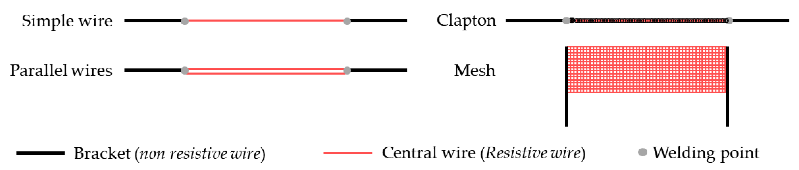
The aim of this publication was to provide a more technical classification of electronic cigarettes. To do so, twenty-six devices were disassembled. Each heating element has non-resistive brackets welded to a resistive part that heats. Four types of resistive parts were observed: a simple wire, two parallel wires, one or two wires with a rolled around non-resistive wire, and a small wire structured in mesh. Except for the Iqos mesh that is too thin to be correctly measured, all the surfaces of the resistive part were calculated using the length and the diameter. Then, the air resistance of each device was determined using pressure drop measurements. Through these experiments, recommended powers, electric resistance, wire surface, and air resistance show two main groups of devices (commonly named classical and sub-ohm electronic cigarettes) designed for two inhalation behaviours: mouth-to-lungs and direct lungs. These groups are limited by a required power of 25 W, an electrical resistance of 1.1 Ω, a wire surface of 71 mm2, and an air resistance of 4.8 Pa0.5 min L−1. Some devices were just between the two groups. The analysis of more devices would allow a better determination of these limits. However, they could be used as requirements for direct lung vaping regimen use.
Through this publication, we exposed necessary elements to grasp the functioning of an electronic cigarette. As explained in the introduction, electronic cigarettes are heat exchangers. The energy delivered is diffused to the air and to the e-liquid. We described the different designs of heating elements available in the devices. With the surface determination, we concluded that a specific heat flux seems to be a constant in most of the devices, and we provided a range of value calculated. This provides an important comprehension of how an e-liquid is heated. Additionally, the air resistance was extracted from pressure drop measurements. These values need puffing topography in order to determine if users inhale at an airflow corresponding to an average constant pressure drop. However, air resistance allows the determination of a characteristic speed of air needed in the calculation of heat exchange coefficient. Future studies will be focused on the thermal behaviour of an e-cig using this technical information.


