1. Introduction
In nature, there are varied modes of locomotion, including flying, clawing, swimming, and jumping, among which jumping is chosen as the dominant locomotion method by many miniature animals, such as fleas, gall midge larvae, and springtails. Jumping as a locomotion strategy is reported to have the following advantages. First, jumping endows noumenon the capacity to overcome much larger obstacles than other locomotion methods. For instance, fleas and froghoppers can attain heights that are more than 200 times [
1] and 100 times their size [
2], respectively. In contrast, it is difficult for wheeled locomotion to achieve such goals. The Mars rover can overcome obstacles about 1.5 times the size of the wheels [
3]. Second, robots jumping in the air will acquire more information than on the ground [
4]. Third, jumping may offer the best compromise for effective and efficient locomotion in millimeter-sized microrobots [
5]. Due to the characteristics of jumping motion patterns, more and more scholars are focusing their research interests on jumping robots.
The first step in the design of a jumping robot is to select high-performance components for energy storage and release. Regarding storing energy, the use of traditional springs is the first choice. The MultiMo-Bat employs six linear springs to store and release energy using two four-bar mechanisms [
6]. The second choice is using a special spring as the energy storage medium, under which circumstance, the miniature robot employs two symmetrical transmutable carbon fiber strips to store and release energy [
7]. The soft robot uses a shape memory alloy to store and release energy for jumping and the same goes for a Tribot [
8]. The third choice is compressed air. The rescue robot [
9] and the Scout robot [
10] both utilize the cylinder’s motions to realize jumping, while some other robots use cylinders to drive four-bar mechanisms to achieve jumping motions [
11]. In addition to the methods above, there are other ways to achieve this goal. By stimulating special materials with light, the Microrobot will gain the ability to jump [
12]. The Sand Flea, which is a design by Boston Dynamics [
13], employs a pneumatic system that uses carbon dioxide as its raw material for long-distance jumps.
Researchers committed to the field of robotics maintain that controlling the magnitude of the energy stored and released is vital. As of today, there are two main ways of regulating the amount of energy stored. The first one is the storage of equivalent energy at every operational time [
14,
15,
16,
17] such that the robot will have the ability to jump up to an immobile height. The GRILLO III robot can reach a vertical height of 0.1 m and a horizontal distance of 0.2 m in a single leap by employing a spring–segmental gear system [
18]. The MSU jumper equips the gear mechanism and one-way bearing to control the robot, which can hop up to a height of 0.87 m and a distance of 0.9 m [
4]. The jumping robot is able to operate itself using a snap-through buckling and can jump a distance of more than 0.7 m and a height of 0.2 m [
19]. The second school of thought is to generate inequality energy to carry loads up to heights that are equivalent to actual demands. The MultiMo-Bat utilizes the SMA clutch to adjust its jumping heights [
6]. This soft robot’s control system consists of eight BMX100 SMA coils, and different values of the voltage will produce different deformations, making it possible for the soft robot to achieve corresponding heights [
19]. The JumpRoACH robot generates variable energy in order to reach appropriate sites using a planetary gear system [
20]. Taking into account energy utilization rates and the environmental adaptation of the robots, the second method will indubitably have more promising developments.
In this paper, we present a route-adjustable miniature steerable multi-locomotion robot with jumping motion as the main part and wheeled motion as the auxiliary part, as shown in
Figure 1. Our design has three requirements. To begin with, the robot has strong mobility, including jumping, running, turning, and righting. Second, the robot should be equipped with strong energy storage ability, which requires the selection of appropriate jumping components and the corresponding actuator. Third, the robot should have an excellent load capacity to install sensors, cameras, and other equipment for practical applications. The details of the whole process of the robot design and manufacture are described in
Section 3 and
Section 4 respectively. The final robot can achieve a vertical height range of 0.98 to 1.23 m and a horizontal distance of about 0.6 m. Specific experiments are described in
Section 5.
2. Bioinspiration from Springtail and Midge Larvae Jumping
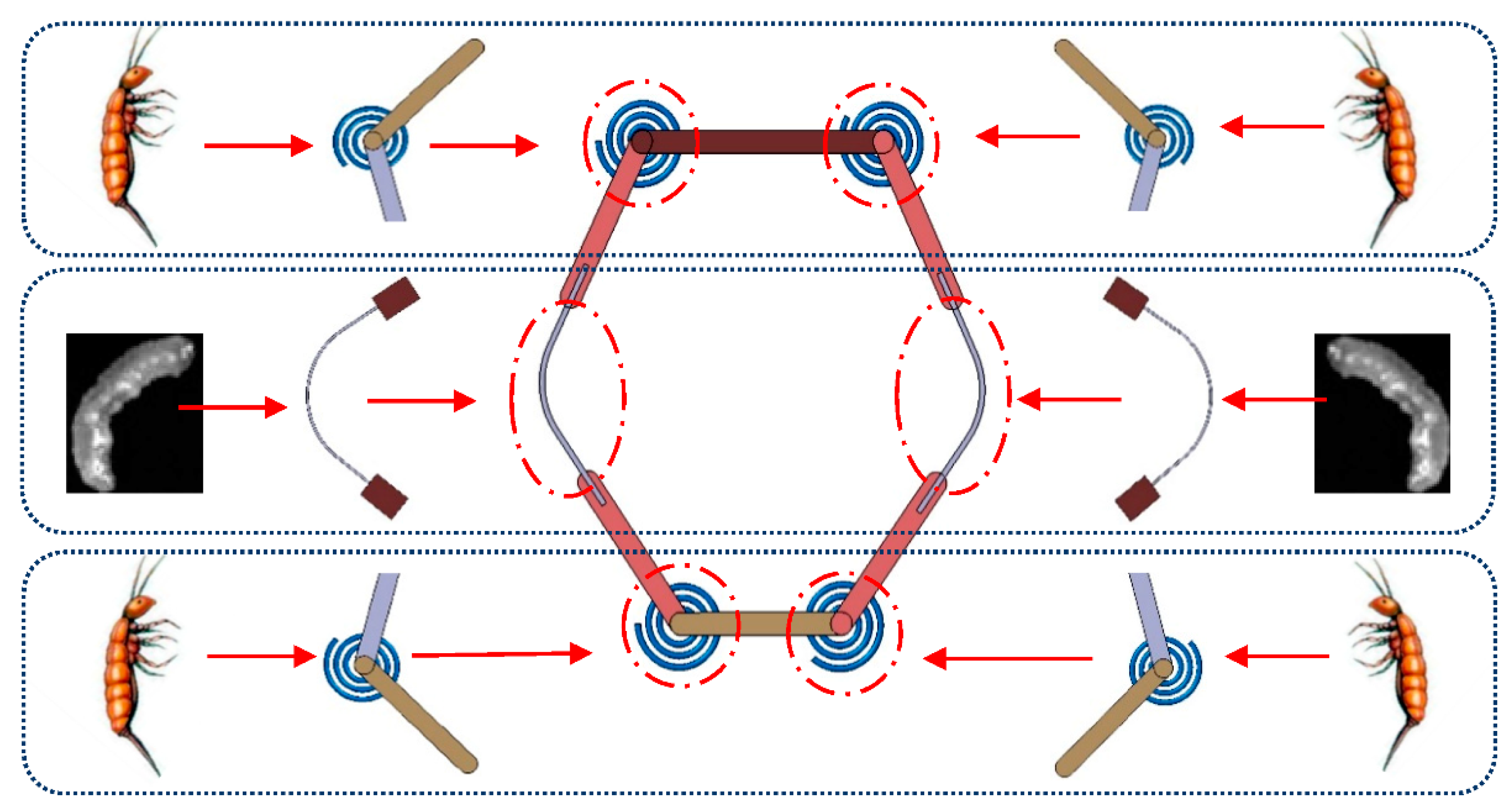
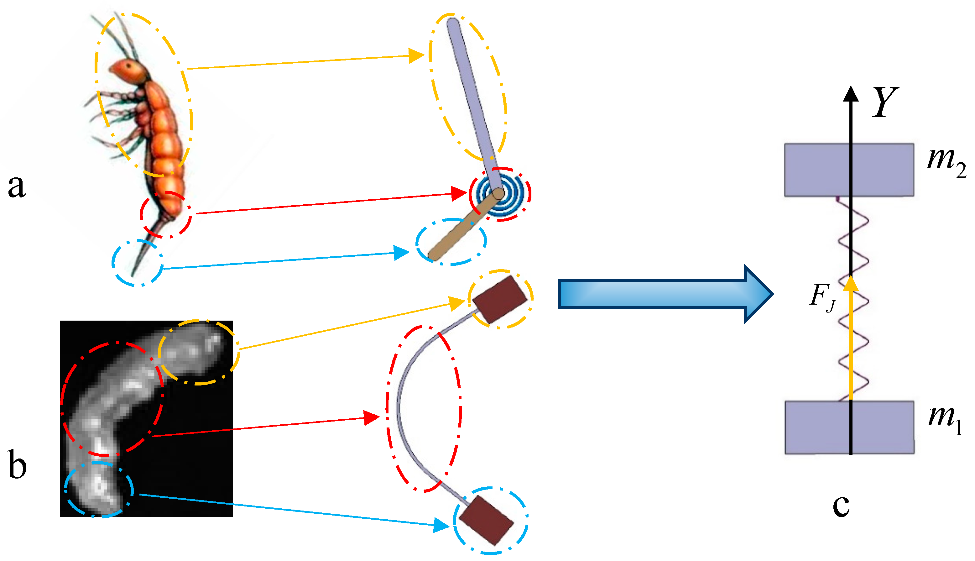
The inspiration for the jumping mechanism of the robot design came from observations of the jumping patterns of springtails. Springtails have a catapult at the end of their abdomen that is connected to the end of their abdomen in the form of a hinge. The movable range of the angle between them is 0–180°. Before taking off, the catapult is contracted under the abdomen at an angle of 0° and then gradually opens from the abdomen and interacts with the ground. Afterward, the body accelerates upward until it reaches the limit angle, which is 180° when the springtail completes the take-off and leaps into the air.
A study of gall midge larvae [
21] published by researchers at Duke University showed that mollusks also have amazing jumping capabilities. Before take-off, the gall midge larva sticks its head and tail together through tiny hairs and stores energy in the middle part of their bodies. It will release the energy for take-off when the energy is greater than the adhesive force between the head and tail.
The jumping mechanisms of springtails and gall midge larvae can be divided into three parts: the upper part, the elastic component, and the lower part. We mimic these in the prototype when designing the bionic mechanism. The bionic springtail jumping mechanism consists of two connecting rods connected by a hinge and a torsion spring inserted at the hinge, as shown in
Figure 2a. Similarly, hyperelastic Nitinol plates were used to simulate the soft body of the gall midge larvae, and joint blocks were installed at both ends of the plates, as shown in
Figure 2b.
3. Design
3.1. Jumping Mechanism
To facilitate the theoretical analysis, we simplified the bionic jumping mechanism, as shown in
Figure 2c. The masses for the upper and lower parts were set to be
and
, respectively. A linear spring was chosen as the elastic element, with the elastic coefficient being
. The elastic force after compression was
FJ.
A coordinate axis was then established with the origin at the take-off point and with the
y-axis along the vertical direction.
According to Hooke’s law:
where
, where the original length of the spring is
.
The analysis of the whole system shows that the interaction between the elastic force and the ground in the mechanism transforms the elastic potential energy into the kinetic energy of the mechanism. The kinetic energy of the system is the work done by the spring-bound counterforce in the ground, that is, the supporting force:
where
denotes the starting point at which the mechanism releases energy, and
denotes the time taken for the mechanism to reach the equilibrium position, at which point, the elastic potential energy will be completely released:
From Equation (5), it can be seen that the kinetic energy of the system when it leaves the ground decreases with the decrease in the interaction time between the mechanism and the ground. When the robot jumps off the ground in advance, the elastic potential energy of the mechanism is not released completely, which will greatly reduce the overall performance. The greater the ratios of the ground reaction force to during the initial release, the greater the possibility of the robot leaving the ground ahead of time.
In order to design a jumping mechanism with better performance, we combined the two bionic mechanisms into a single mechanism, as shown in
Figure 3. In consideration of the respective characteristics of the two bionic mechanisms, the bionic springtail jumping mechanism was assembled at the top and bottom of the overall mechanism, and the bionic gall midge larvae mechanism was assembled at the middle of the overall mechanism. The combined mechanism has a symmetrical structure. In this case, the jumping ability and stability of the mechanism were greatly enhanced.
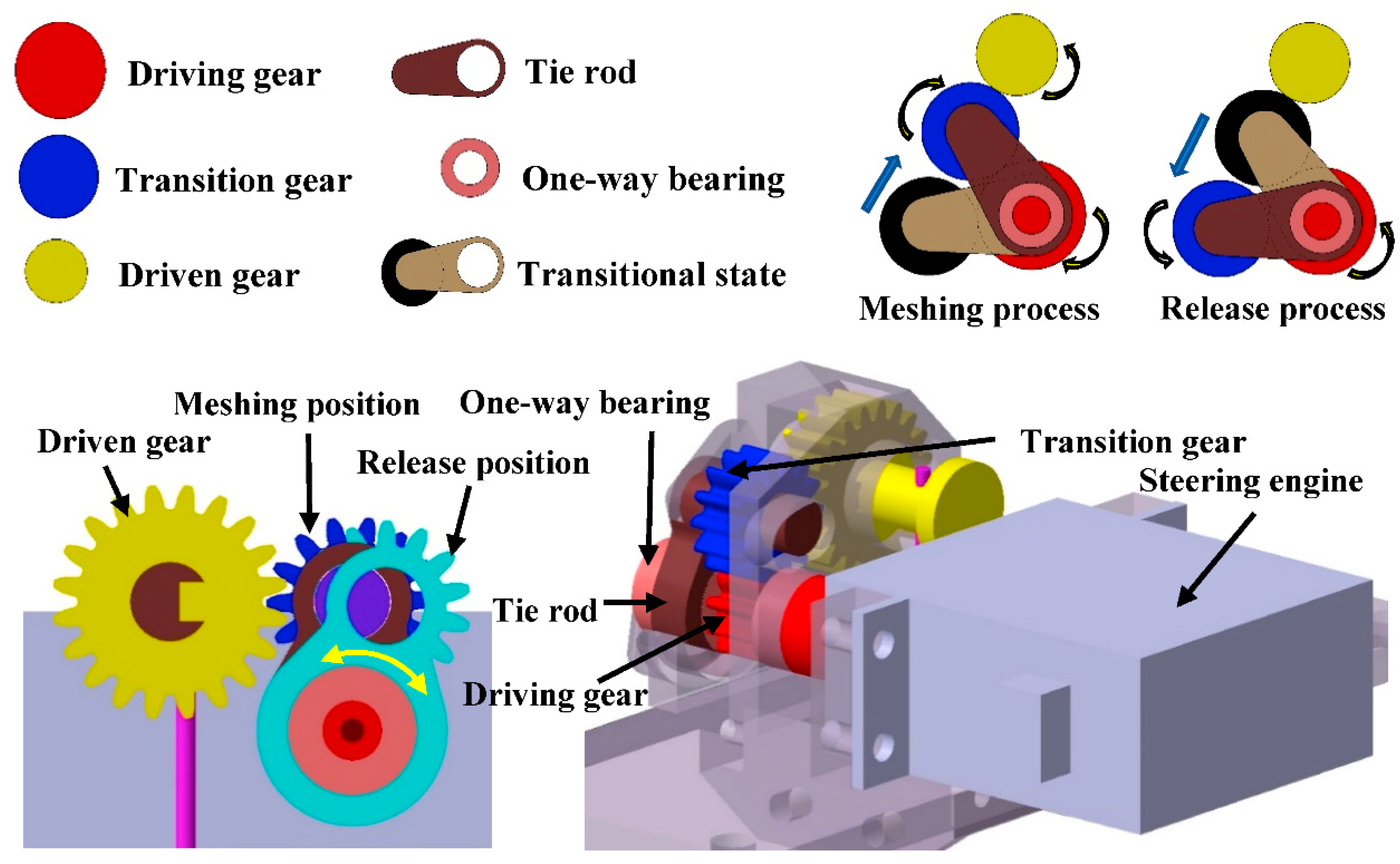
3.2. Height-Adjustable Triggering Mechanism
To achieve the jumping mechanism to release the stored energy in any state, an epicyclic gear train was chosen, as shown in
Figure 4. When the driving wheel rotates clockwise, it makes the transition gear mesh with the driven gear through the actions of the tie rod, thus delivering power using the stored energy. In contrast, the driving gear rotates counterclockwise and drives the tie rod to rotate counterclockwise through a one-way bearing such that the transition gear is separated from the driven gear, the mechanism releases energy, and the robot performs its jumping movement. Although the clutch is similar to the clutch used by the JumpRoACH robot [
20], there are underlying differences in its application principles. In the clutch we designed, the meshing and separation of the transition gear and the driven wheel are realized by the driving wheel driving the tie bar through a one-way bearing, while the clutch of the JumpRoACH robot is realized directly by the meshing force between the gears. Through replicated experiments, we found that JumpRoACH’s clutch design has very low reliability. The disengagement of the transition gear is often prevented by meshing forces between the gears, while the problem of low reliability is effectively avoided by using a one-way bearing to transmit power.
3.3. Self-Righting Mechanism
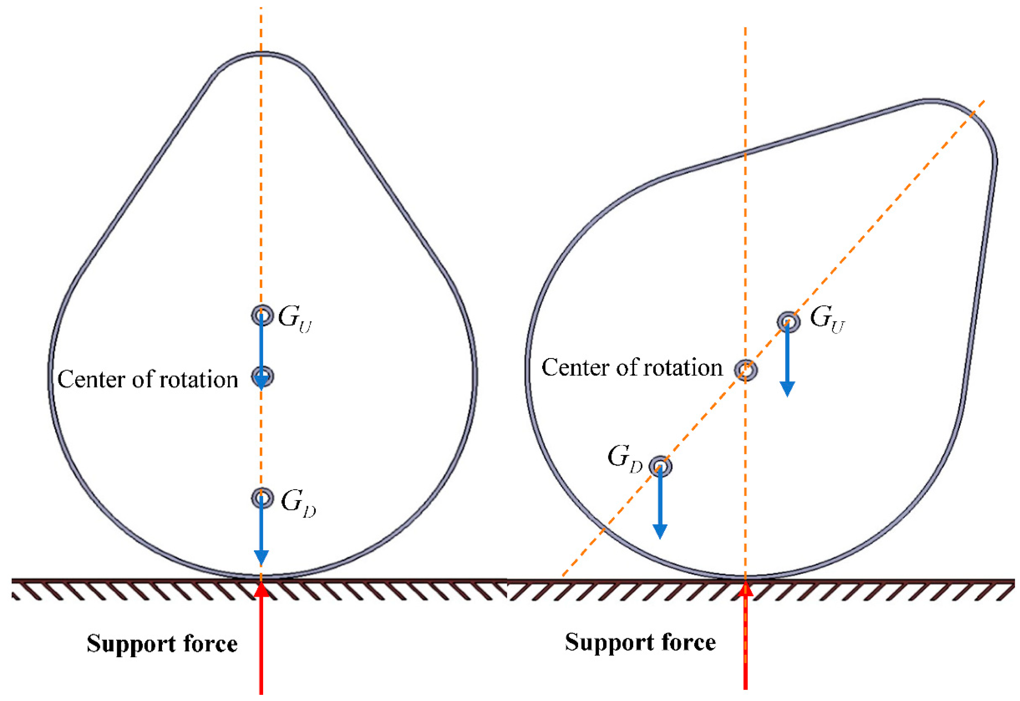
It is very difficult for a robot to get back into the right take-off position due to the uncertainty caused by jumping; therefore, the robot must return to its proper posture in time before it can continue to move. Inspired by the tumbler, we applied the principle of the tumbler to the robot so that the robot can self-upright. The center of gravity for a tumbler is placed below its centroid, and after jumping, it will return to its original posture due to gravity.
When a straight line of gravity passes through the robot’s centroid, the force of gravity and the supporting force become a pair of acting and reacting forces regardless of whether the center of gravity is above or below the centroid and the robot will continually maintain its balance, as shown in
Figure 5 (when the center of gravity of the robot is located at the top of the centroid, its center of gravity is represented by
; when the center of gravity of the robot is located at the top of the centroid, its center of gravity is represented by
). If the robot falls when the center of gravity is below its centroid, the robot will be subjected to gravity and return to its equilibrium posture. In contrast, when the center of gravity is above the centroid, the robot will fall further. For gravity to help the robot regain its balance, we placed the robot’s center of gravity below its centroid. The lower the center of gravity, the stronger the robot’s self-righting ability.
In practical applications, the robot’s shell is designed to be hollow with a flat bottom. The jumper unit is mounted at the bottom of the shell and can be retracted from the shell while jumping.
4. Fabrication
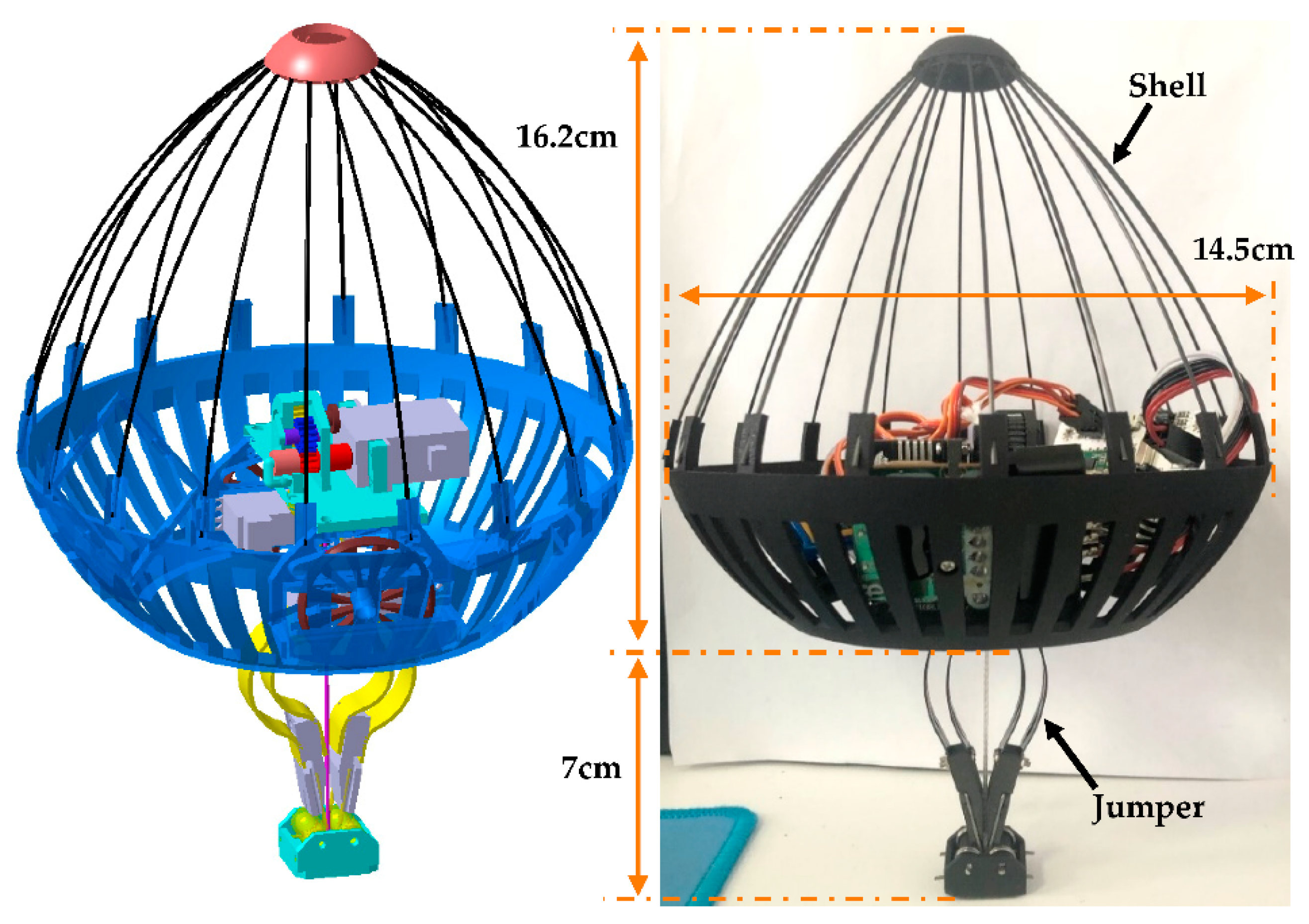
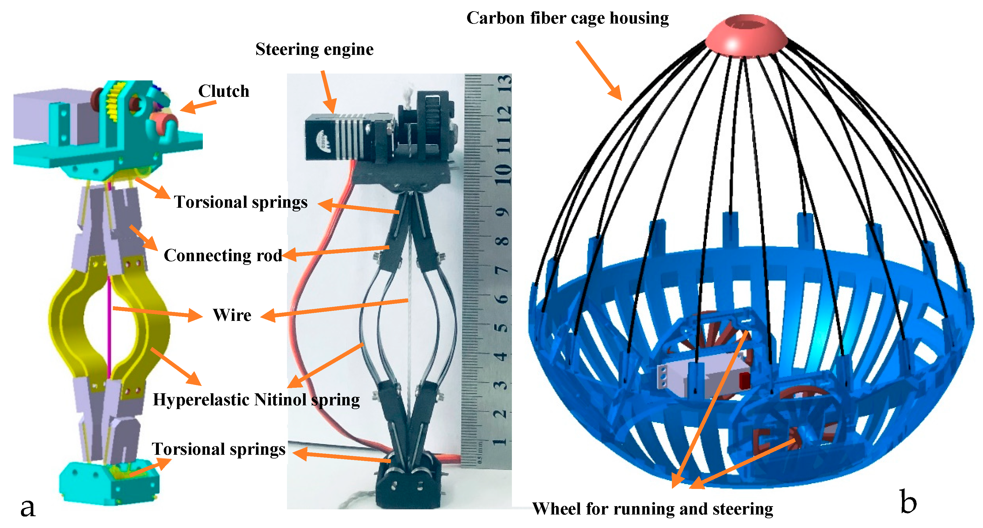
The robot is composed of a jumper unit and a shell unit. The jumper unit consists of a six-bar jumping mechanism, a clutch mechanism, and a steering gear, as shown in
Figure 6a. The shelling unit includes a carbon fiber cage housing for protection and self-righting, as well as a chassis part for running and steering, as shown in
Figure 6b. This section provides further elaboration on the manufacturing and working mechanisms of the robot’s components.
The jumping mechanism model and prototype of the robot are shown in
Figure 6a. In addition to two kinds of elastic components, all other components of the combined jumping mechanism were manufactured using 3D printing technology, and nylon was used as the printing material. The Nitinol plate was connected to the connecting rod by screws, and the torsion spring was connected by U bolts. The lower part of the six-bar mechanism jumps directly from the ground, while the upper part carries the entire weight of the robot.
The principles of the energy control system were described in detail in previous sections. The control system uses GDWDS296X steering gear, with an output of 7.8 kg/cm torque at 7.4 V. The gear system is also 3D printed using high-performance nylon material, and it has 10, 16, and 30 teeth respectively. The deceleration ratio is 3. A one-way bearing (HF0306) is installed at the end of the driving wheel and two bearings (MR63-2Z) are installed at both ends of the output wheel. Finally, a wire is used to connect the output wheel and the six-bar mechanism base for the control of energy storage and release.
The running and steering mechanism is achieved by controlling two wheels with two motors, allowing the robot to move and turn quickly on flat surfaces. The motor was directly connected to the wheels and was mounted at the bottom of the robot’s shell. The wheels and shell were manufactured using 3D printing.
The robot’s shell is divided into two parts; the upper part and the lower part. The parts of the robot were installed in the lower half of the shell to keep the robot’s center of gravity as low as possible. This part has the strength requirement and therefore uses high-performance nylon materials. The upper part has no special requirements, but the lighter the better. It is woven with carbon fiber rods. The quality specification of the robot’s components is shown in
Table 1.
5. Results
To show the actual performance of the robot, a series of experiments were conducted using the robot with the aim of determining its jumping height, horizontal distance, and energy utilization. In this specific experiment, the slow-motion recording function of a camera was used to shoot the whole jumping process of the robot. The camera parameters were set to 1080p HD and 240 fps. A rigid cement floor was selected as the test site for this experiment in order to eliminate the energy loss into the ground during takeoff. The height and distance of the robot’s jumping were obtained in the video by using a scale that was placed next to it (see the lab video file attached to this paper for details).
First, we carried out a series of jumping trajectory experiments on the robot and reflected the maximum trajectory and the minimum trajectory in
Figure 7. The trajectory of the robot was determined via the jumping movement in the vertical direction and the wheel movement in the horizontal direction. When the robot’s jumping mechanism was compressed to the limit, the initial jumping speed was upward at 4.9 m/s and the horizontal speed of the robot was set to 0.61 m/s. At this time, the robot reached a maximum jumping height of 1.2 m and a maximum horizontal span of 0.6 m. The robot’s motion trajectory is shown in the red curve in
Figure 7. When the robot’s jumping mechanism was compressed to the minimum set value, the vertical speed of the robot was 4.4 m/s and the horizontal speed was set to 0.5 m/s. In this case, the height and horizontal span of the robot’s jump were 0.98 m and 0.44 m, respectively. The robot’s motion trajectory is shown in the blue curve in
Figure 7, where the gray shaded part denotes the minimum barrier range of the robot, while the green shaded part represents the adjustable range of the robot’s motion trajectory.
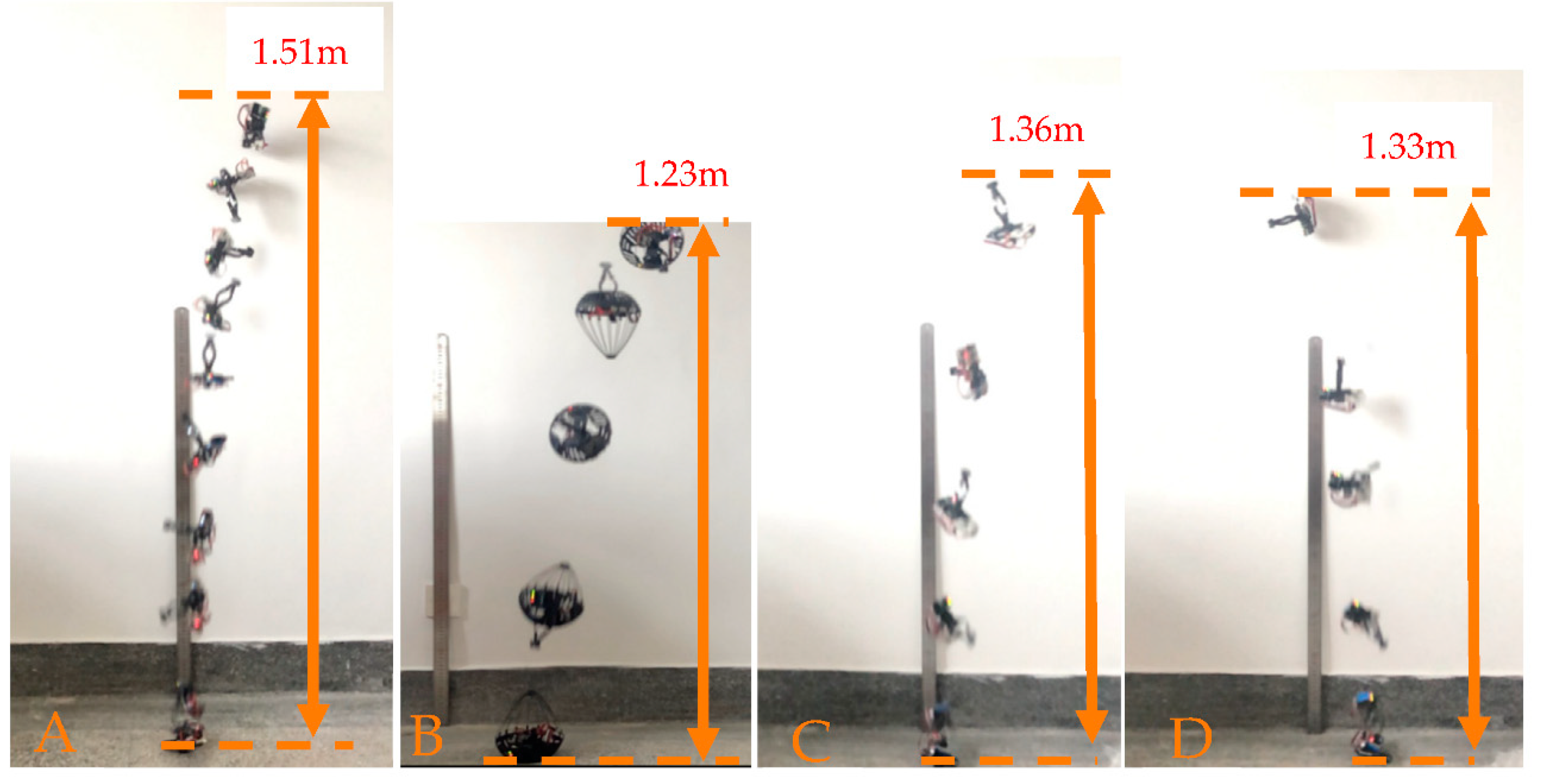
The jumper component of the robot provides energy for the robot to jump. An increase in the robot’s mass will result in a reduction in the height of its jumping, hence the need to minimize the mass as much as possible. However, in order for the robot to have steering functions and to have stronger movement abilities on smooth ground, an increase in the mass of the mechanism is inevitable to realize the above functions, thus increasing the quality of the robot. Consequently, experiments were designed to test the effect of adding a shell and steering mechanism on the height of the jump. With no shell and steering mechanism, the total mass of the jumping mechanism, control panel, battery, and Bluetooth receiver was 98.6 g, compared to 156.8 g for a complete robot with a shell and steering mechanisms. The difference in mass between the two was 58.2 g. The jumping mechanism is released immediately after full compression for vertical take-off. The jumping height of the device without a shell and steering mechanism was 1.51 m, as shown in
Figure 8A, while that for a robot with a complete structure was 1.23 m, as shown in
Figure 8B. The height was reduced by about 0.2 m.
When the load of the jumping mechanism was 98.6 g, the height of the jump was 151 mm, as shown in
Figure 8A. The energy utilization efficiency was calculated as being 51.3%. When the load of the bouncing mechanism was 156.8 g, the height of the jump was 123 mm, as shown in
Figure 8B. The energy utilization efficiency was increased to about 66.5%. In order to increase the reliability of the experimental results, we added 30 g of mass on the basis of having 98.6 g for the jumping experiment. The height of the jump was 136 cm, as shown in
Figure 8C, and the energy utilization rate was approximately 60.3%. When the energy storage mechanism was not fully loaded, the compression height was at 60 mm and the energy stored was 2.1 J, while the height of the jump attained was 133 mm. The energy utilization rate was approximately 62.4%, as shown in
Figure 8D. From the above data, we ratiocinated that for a specific jumping performance, the height of the jumping will reduce with an increase in the load size, but that is not the case with energy utilization ratio and load. A particular jumping mechanism will have an optimal load under which the energy utilization rate of the jumping mechanism reaches the maximum.
Energy loss will occur as a consequence of the following activities by the robot. First, vibration during the release of the elastic elements will lead to energy loss. Second, energy loss will occur due to the frictional forces during the jumping process, where each node of the six-bar mechanism will interact with each other. Third, the robot’s energy is consumed by air resistance.
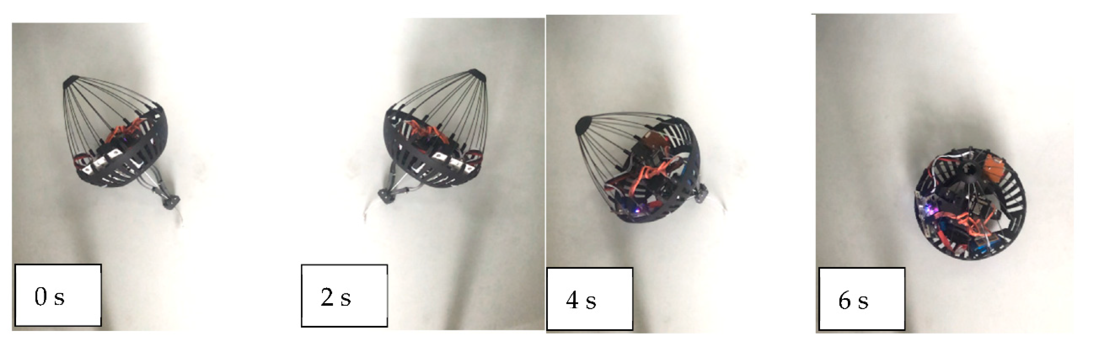
For the robot’s passive righting function, we also carried out some experimental tests. After the robot takes off, its jumping mechanism extended out from the bottom of the shell with a length of 72 mm. Therefore, the jumping mechanism only needed to be withdrawn 72 mm inward in order to make the robot return to the positive position. As seen in multiple tests, it took 6 s for the jumping mechanism to shrink to the required 72 mm, which is part of the process of storing energy precisely. Therefore, it does not take any extra time for the robot to take off again.
Figure 9 shows four screenshots from the video of the robot returning to the positive position.
6. Discussion
Some scholars have proposed bionic jumping robots with excellent performances. There appears to be no related work on bionic jumping robots that were modeled using the integration of the jumping mechanisms of soft-bodied and hard-bodied animals. The uniqueness of this study is that it creatively integrated the jumping mechanisms of two animals to achieve the robot’s jumping ability, thereby significantly enhancing the energy storage and stability of the robot.
Currently, most jumping robots have strong jumping abilities, but scholars did not focus their attention on the payload capacity of robots. When the mass of the MUS Jumper robot [
4] increased by 4 g and 8 g, the height of the jumping decreased by about 5.8% and 20.3%, respectively. The jumping robot dropped its jump height by 38% from 111 cm to 69 cm in order to after its weight was increased by 6.76 g [
22]. The robot proposed in this paper has a stronger advantage in terms of its load. When the load of the mechanism was increased by 30 g and 58.6 g, the height was reduced only by about 9.9% (151 cm to 136 cm) and 18.5% (151 cm to 123 cm), respectively. It is not easy to make a fair comparison of the jumping robots due to the variations in size and weight. Considering that the robot’s mass and jumping height reflect its jumping ability and load ability, the size of the jumping mechanism limits its ability to store energy. Therefore, we introduced a reference factor
, where
and
are the total mass and the jumping height of the robot, respectively, and
is the size of the robot’s jumping mechanism. We then compared the current excellent jumping robots, as shown in
Table 2.
The comparative analysis revealed that the robot is suitable for carrying various types of lightweight equipment in practical applications, which will not significantly impact its performance. Compared to the existing jumping robots, the one we designed appears to have better practical applications.
7. Conclusions
This study proposed a biologically motivated route-adjustable miniature multi-locomotion robot. We designed the bionic mechanism of the gall midge larvae that belongs to soft-bodied jumping animals and the springtail that belongs to hard-bodied jumping animals; we then combined the two bionic mechanisms to obtain a jumping mechanism with superior performance. Compared with existing jumping robots, our robot displayed the following characteristics. First, it had a powerful energy storage capacity that was up to about 2.9 J of energy at a height of about 10 cm, this was capable of endowing the robot with strong load capacity and jumping ability, which was well reflected in the experimental data. Second, it could adjust its locomotion trajectory based on the obstacle’s size through a combination of horizontal and vertical motions. Furthermore, it could be automatically righted by gravity after a fall, thus eliminating the need for any additional righting mechanisms.
Compared with the existing robots, our robot achieved functions of height-adjustable jumping motion, wheeled motion, and self-righting in the smallest possible size. More importantly, our bouncing unit has better energy storage and load capacities in the smaller size.
In the future, the robot can be equipped with sensors, cameras, and other tools for military monitoring, reconnaissance, and outer space exploration. In practical applications, it can be improved according to actual situations, such as the selection of more elastic components or a more powerful motor.


