1. Introduction
Nowadays, one of the main problems with which aviation is faced is noise pollution [
1] and the need to heavily reduce the noise exposure of the areas adjacent to airports.
In aviation, the most important noise sources are the take-off and landing phases of flight. For most commercial jets, the primary noise sources are the engines. The secondary one originates in the airflow around the aircraft (aerodynamic source) [
2].
In terms of aircraft noise sources [
3], the engine noise has one of the highest proportions [
4] where the jet noise has an important contribution.
There are many studies and research projects treating the jet noise reduction [
5,
6], but the simplest technique is to manufacture chevrons on the nozzle without having high loss of the propulsion force [
7,
8,
9,
10,
11].
By definition, the chevrons are dynamic gas equipment that, by initiating the vortical flow, smoothens the mixture of the two flows, having different velocities, and decreases the resultant noise of those flow interactions [
12]. These solutions were proposed for the first time by the Lighthill in 1952 [
13], and since then, these were studied and developed, and complex geometries resulted. For example, the fluid chevrons [
14,
15], stepped nozzles [
16], and nozzle are manufactured from smart material [
17].
As was mentioned before, these solutions were heavily studied, but there are no studies in which the nozzle with chevrons, to be mounted on a turbojet engine, and the performance influences are assessed [
18].
The research projects performed on Boeing 737-max 747-8, 787 and Bombardier CRJ900 aircrafts, have implemented on the Trent 1000 (Rolls Royce), GE90 and GE CF34—8C5 engines, nozzles with chevrons [
19,
20,
21,
22].
One might observe that, in specialized literature, we find many studies of chevrons’ acoustic effects. Most of them present studies of chevrons’ effects on nozzles, or on simple pipes working with air, but there is a missing part when we think about the effects of chevrons on the turbojet performances. The present paper proposes a study of the chevrons effects on the acoustic and turbojet performances using a test bench equipped with a micro turbojet engine.
This paper will focus on noise reduction of the micro turbojet engine JET CAT P80, which is used on drones [
23] or for academic purpose [
24]. The paper novelty consists in acoustic and performance evaluations of this engine tested with three different nozzles (straight nozzle considered the reference and two nozzles with chevrons one with 8 chevrons and the second one with 16 chevrons, both having the chevrons length of 10 percent from the equivalent diameter and immersion angle of zero degrees) at different functioning regimes of speed. The laboratory tests were focused on acoustic evaluation of each nozzle and the engine parameters (compression ratio, air and fuel flow, temperature after the compressor, and in front of the turbine, and the vibrations on axial and radial directions).
2. Experimental Test Bench
The measurements were performed on the micro turbojet engine Jet CAT P80 [
25]. which is in the endowment of the aerospace engineering faculty of the Polytechnic University of Bucharest. The acoustic and vibration measurements were performed by using the multi-channel acquisition system, Orchestra, from 01 dB, and the vibrations were measured on axial and radial direction with two accelerometers PCB 352C03 mounted on the engine supports, the noise was recorded with 3 microphones GRAS 40 AQ. The microphones were placed at 0.4 m from the engine nozzle and 0.4 m between them as is presented in
Figure 1.
A detailed study with noise assessment of this micro turbojet engine can be found in reference [
26], where the experimental studies for 2 turbo jet engine regimes were made, in the anechoic chamber of the Acoustic and Vibration Laboratory of the National Research and Development Institute for Gas Turbines COMOTI, and the directivity patterns of both regimes, were performed from the acoustic signals of the microphones dispose around the engine.
As is presented in
Figure 1, the entire engine is held by two supports mounted on a sliding board that pushes into a force transducer. On these supports, the two accelerometers were placed, Acc1 in axial direction, Acc2 in radial direction, and the microphones were mounted in a straight line, where Microphone 1 is situated to the right of the nozzle.
The measurements were performed with the engine running in four different regimes (35,000 RPM, 55,000 RPM, 101,000 RPM, and 116,000 RPM) for the three tested nozzles. Each regime was performed by keeping the speed constant for a duration of 1 min, the measured parameters being averaged in this time period.
3. Designing and Manufacturing the Chevrons Nozzles
The main parameters which define the chevrons are: chevrons number N, length L and the immersion angle I [
27]. According to the study presented in [
28], it is recommended that the chevrons’ length be between 5 and 10 percent of the equivalent diameter. The first step of the study was to scan the reference nozzle with ATOS 5 M 3D Optical Scanner, from which the digital 3D model result is presented in
Figure 2.
The chevrons were designed on the 3D reference model and the geometrical parameters of these nozzle type being: N is the number of the chevrons; L is the chevrons’ length, and I is the immersion angle of the chevrons inside of the gas jet. In this paper, only the number of chevrons is assessed. The other parameters being maintained are constant.
The tested nozzles are presented in
Figure 3, the first one being the reference nozzle with an equivalent diameter of 44.3 mm, the second nozzle is the one with 8 chevrons with a length of 10% from equivalent diameter of the baseline nozzle having an immersion angle of
and the third nozzle has 16 chevrons and the other parameters are the same as nozzle 2, as is presented in
Figure 3 4. Acoustic Evaluation Results
In the present study, it is investigated how the noise reduction, produced by the hot jet gases through 2 nozzles with chevrons, compares with the reference nozzle. It must be mentioned that, while the micro engine is functioning, besides the jet noise, there are many other noise sources generated by: air circulation at intake level, turbulences generated by the air passage through compressor stage, mechanical noise generated by the speed of the shaft, rotor-stator interaction, known as Blade Pass Frequency BPF, combustion noise, etc.
One of these types of noise, identified in this study, is the combustion noise, which is composed from two components: direct noise and indirect noise. Regarding the direct combustion noise, this is produced from the fluctuations of the heat release inside the combustion chamber in the flame region. Indirect noise is produced by the entropy waves, induced by the unsteady combustion process and vorticity. These two different noise sources will propagate through (potentially) multiple turbine blade stages to finally radiate in a far field.
The noise of interest, evaluated in this study, is the jet noise, which is produced due to the turbulent mixing of high-speed gases with the ambient air [
29].
In order to compare the noise reduction, produced only by the jet gases, with the chevrons nozzle, it is necessary to identify the acoustic spectral components of the acoustic sources, which were previously mentioned, followed by the filtering of those that are not in our interest.
The data of the engine parameters, and the acoustic and vibration signals, were recorded and post processed, and their centralization is presented further on. The acoustic and vibration raw signals were processed using the Fast Fourier Transform (FFT) function in frequency domain and by averaging the entire time duration. For a better comparison and graphical representation, the noise spectra obtained for the three microphones were averaged according to the Equation (1), thus, for each regime and tested configuration, a spectrum resulted.
where
Lp is the averaged sound pressure level,
n is the microphone number and
Li are the sound pressure level in each microphone in dB.
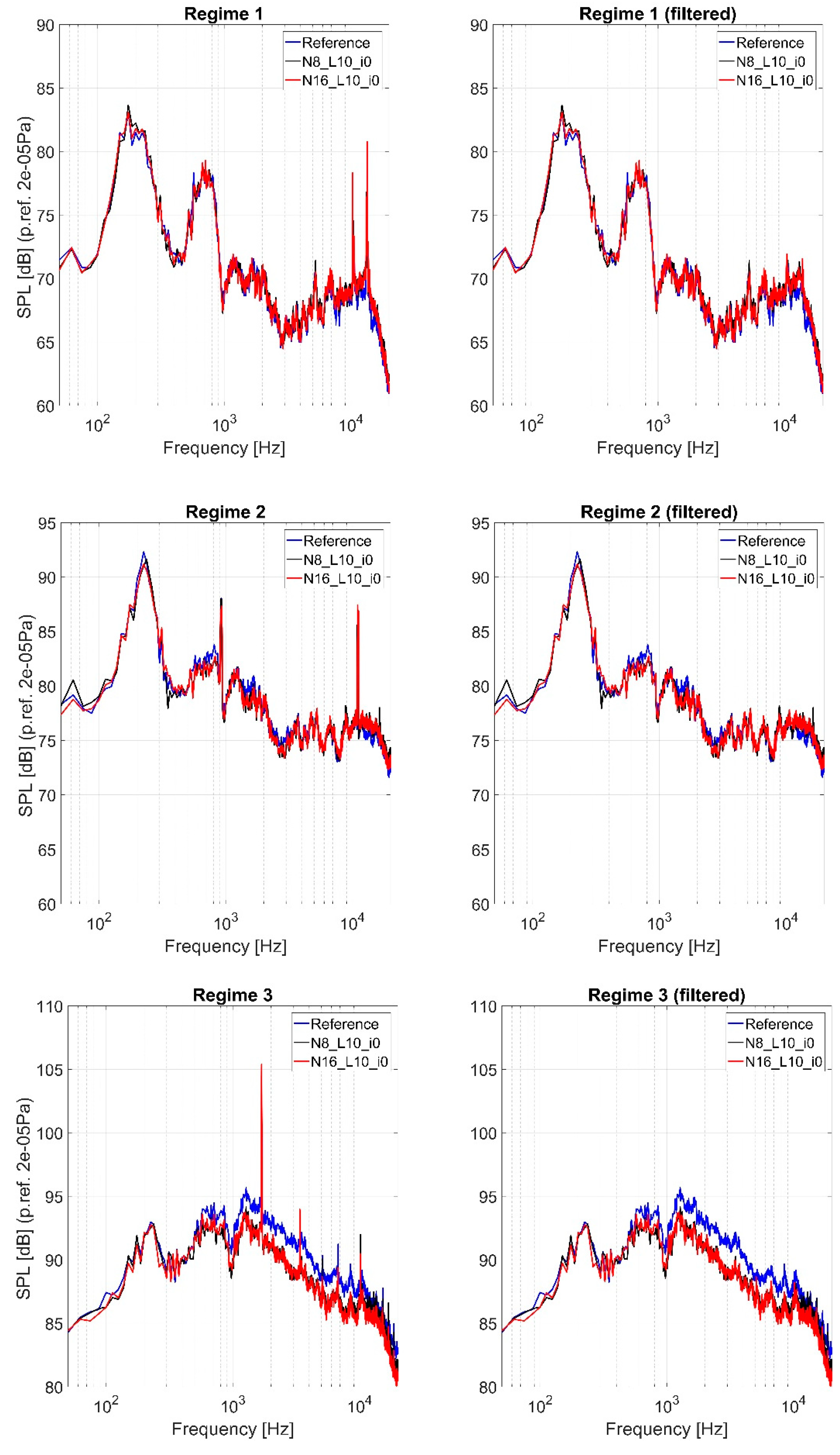
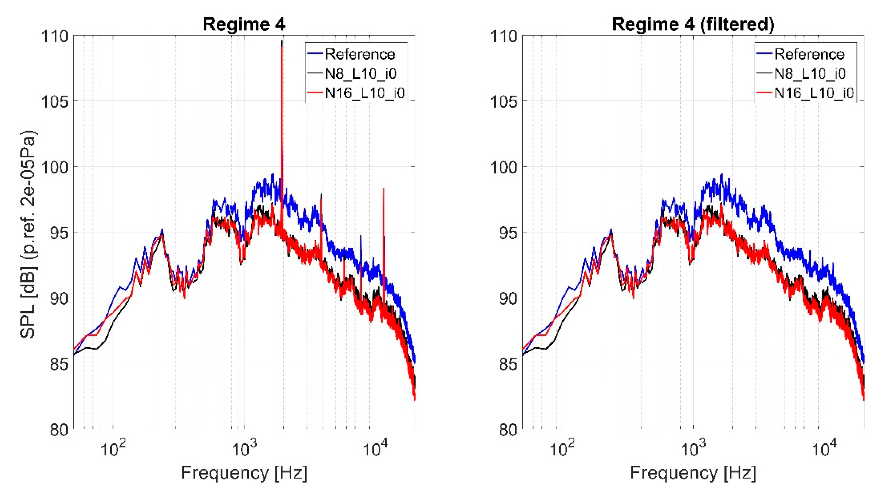
First stage of noise signal filtering was made by applying a band stop filter on the spectral components, which corresponds to the shaft speed, from which it results the compressor, turbine BDF, and its harmonics. In
Figure 4, the unfiltered and filtered averaged sound spectra for each regime and nozzle configuration are presented.
From the unfiltered noise spectra, it is observed that the tonal components corresponding to the engine speed, BPF components, and its harmonics have amplitudes that reach almost 110 dB (especially at high speeds Regime 3 and 4), and applying the band stop filter leads to a broadband acoustic spectrum. Comparing all the spectra from all regimes it identified a broadband component with the peak at a frequency of around 200 Hz, which regardless of engine speed, its maximum peak frequency does not change significantly (max 80 Hz frequency shift), instead its amplitude increases from 83 dB at Regime 1 to 95 dB at Regime 4. It is assumed that this component is produced by the combustion, and this will not be taken into account in overall sound pressure level calculation.
The overall vibration and sound pressure levels (OASPL) in each microphone, and for each regime and nozzle, are presented in
Table 1. The acoustic OASPL were computed based on the filtered acoustic spectra presented in
Figure 4 in frequency domain of 500–20,000 Hz.
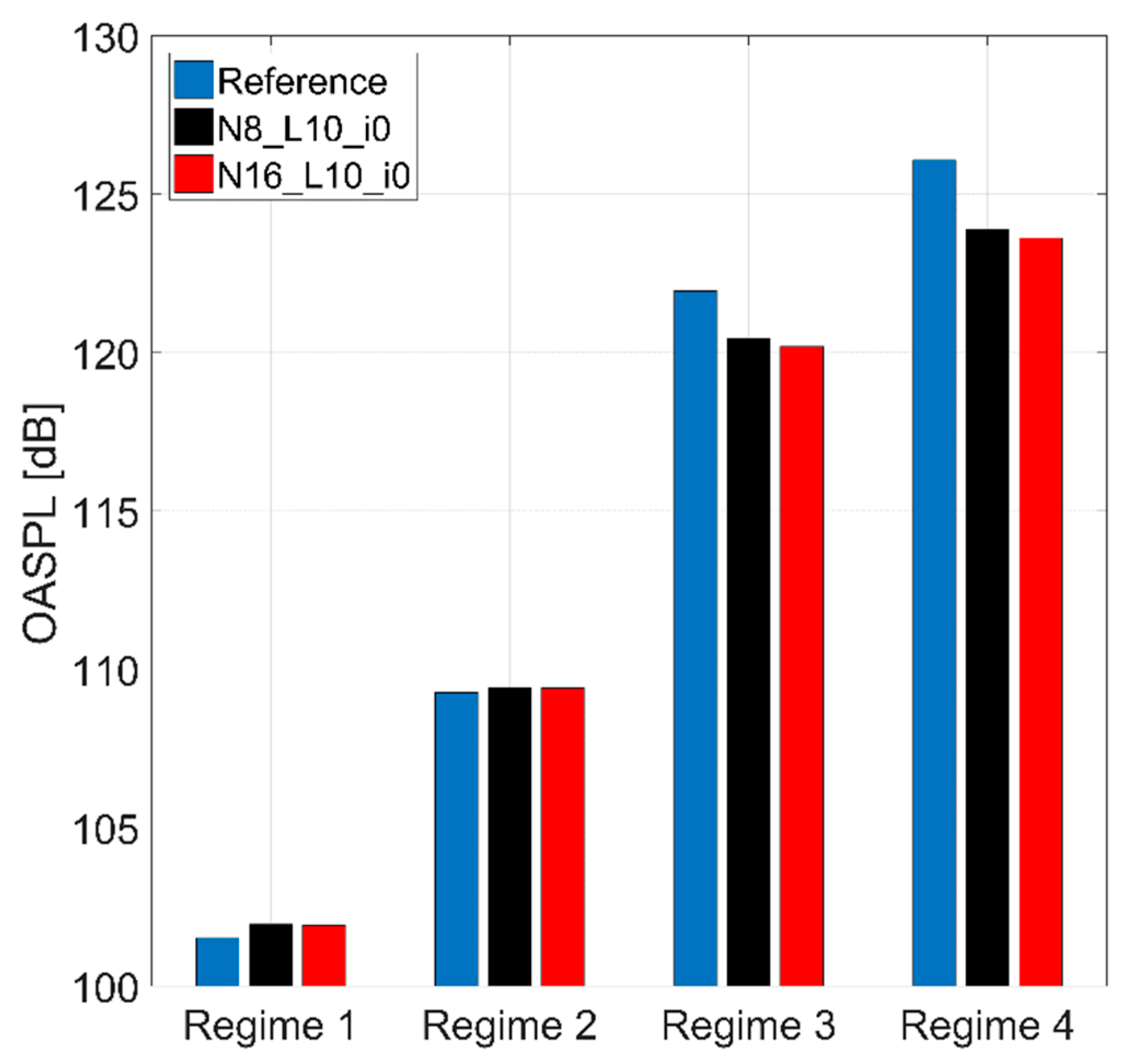
Based on the OASPL in each microphone presented in
Table 1, the averaged OASPL was calculated for each regime and nozzle configuration, the results being presented in
Figure 5.
Based on these OASPL presented in
Figure 5, the noise reduction of the chevron nozzles were computed, taking, as reference, the baseline nozzle noise. The noise reductions for each chevron nozzle, at each regime is presented in
Figure 6.
For the first two regimes, the chevron nozzles lead to a slight increase in the noise, while at higher regimes with high velocities of gases, the chevrons are beginning to become effective, and the noise is reduced with almost 3 dB.
For the first two regimes, that are not stable from the functioning point of view, the chevrons effect is no longer reducing the noise. On the contrary, it can be observe that the noise level has a small increase of almost 0.5 dB. An assumption of the noise increase at the first two regimes is that, by reducing or shortening the nozzle with chevrons, the noise from inside of the engine is propagating easier, with the larger surface of the reference nozzle acting as an obstacle. Another assumption of the noise increase is related to the modification of the engine work line.
An important result is that the nozzle cu N = 16 has a better impact on reducing the sound pressure than the one with N = 8.
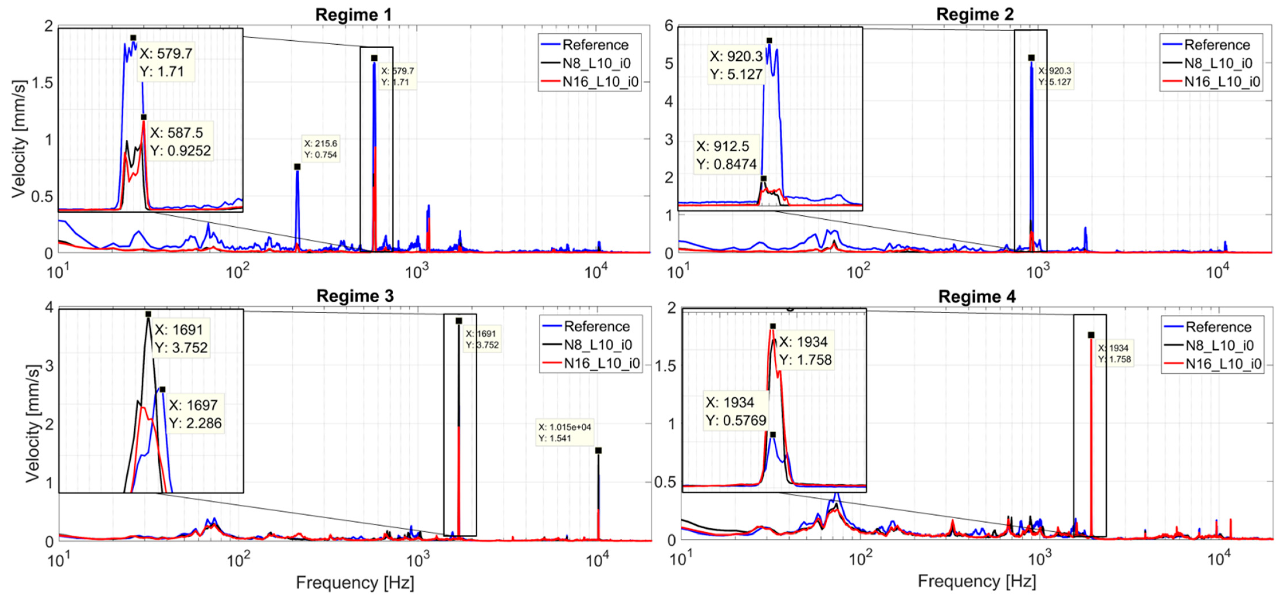
The analysis of vibration signals from
Table 1 indicates that, in the axial direction, the vibration levels are higher than in the radial direction, and the comparison between the tested nozzles does not indicate a specific rule of the vibration variation with the engine speed. In the case of the vibrations, it is necessary to perform a FFT analysis of the raw signals to identify the spectral components that produce these vibrations. In
Figure 7, the vibration spectra on axial direction for each regime and tested nozzle is being presented.
The vibration spectra highlight that the main vibration source corresponds to the engine speed for each regime. For the first two regimes, the speed component has higher amplitude for the reference nozzle, and for the last two regimes, the chevron nozzle configurations obtain higher vibration. Due to the fact that the vibrations are caused mainly by the shaft speed, the replacement of the baseline nozzle with one with chevrons cannot affect the mechanical part of the engine. However, all these vibration variations do not endanger the stability and the integrity of the turbo engine.
5. Micro Turbojet Engine Experimental Performances Evaluation
The measured parameters from
Table 2 were used in performance evaluations of the chevron nozzles. It measured the temperature in front of the micro turbojet engine, which was considered as being the temperature at intake level T
1. Using these parameters, the specific consumption and engine efficiency were computed. The relations used in the calculation of specific consumption and compressor efficiency are further presented [
30]. The specific consumption S is defined in Equation (2):
The compressor efficiency
is defined in Equation (3):
where
is the specific heat capacity and k is the adiabatic exponent.
The measured engine parameters, presented in
Table 2, were used for the calculation of the specific consumption and the compressor efficiency.
During the measurements the environmental temperature (T1) value was T1 = 290 K, and it was measured near the intake engine.
For a better overview of the engine parameters presented in
Table 2, and their variation during the tested regimes, the following graphs present the force losses, fuel consumption, and compressor efficiency in comparison with the reference nozzle (
Figure 8,
Figure 9,
Figure 10,
Figure 11 and
Figure 12).
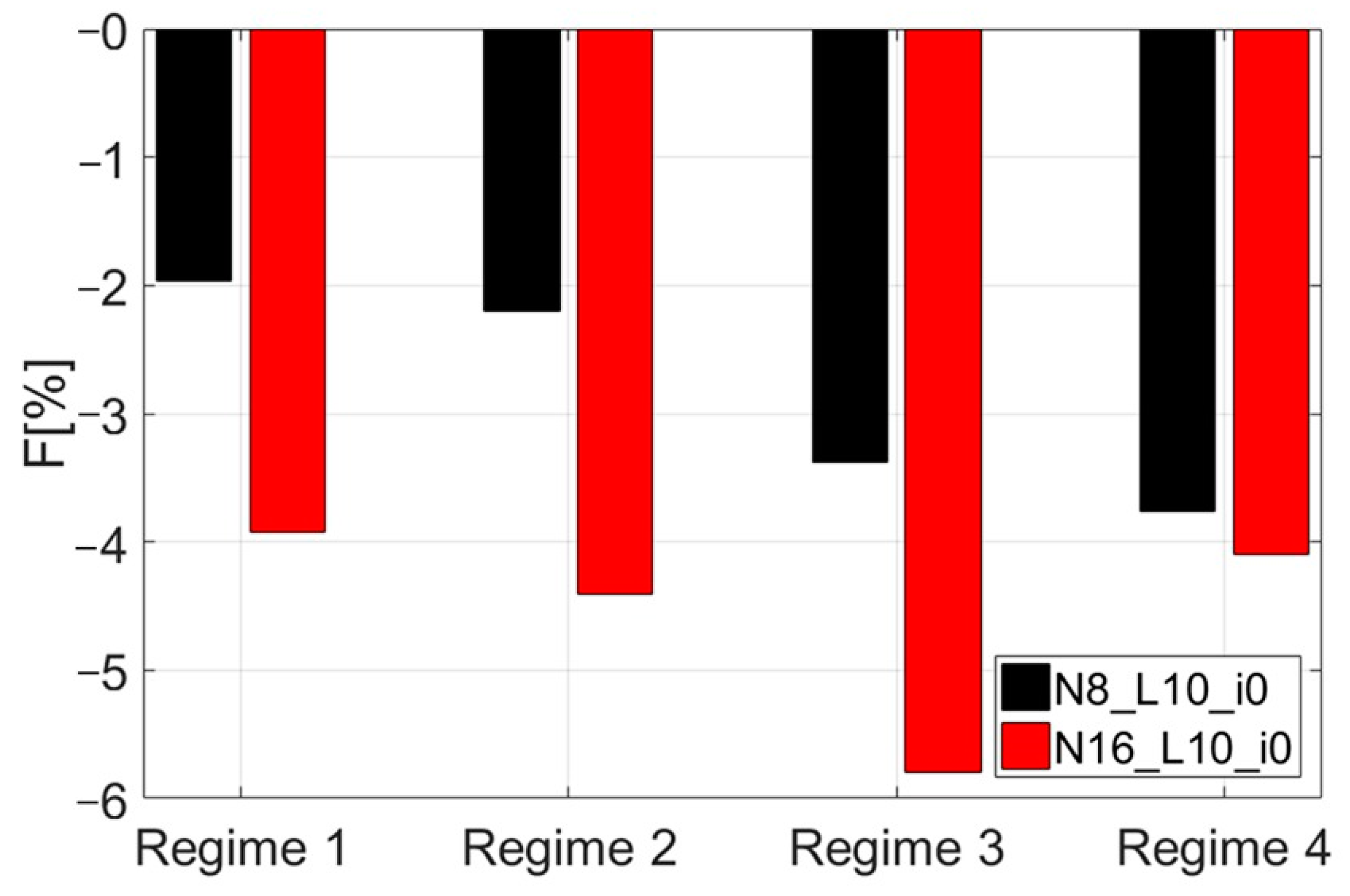
The recorded parameters highlight that the temperature in front of the turbine drops by increasing the number of chevrons in idle regime 35,000 RPM, 100,100 RPM, 116,000 RPM, but it has a tendency of remaining constant with a slight increase at 55,000 RPM. The compression ratio of the engine at low regimes (idle and cruise) doesn’t present variations, but at high regimes, the compression ration drops when the chevrons’ number increases. For the all tested regimes, the fuel flow decreases by increasing the chevrons’ numbers. One of the most important observations is related to the generated force, which decreases by increasing the number of chevrons, and the same downward trend is observed for the intake air flow.
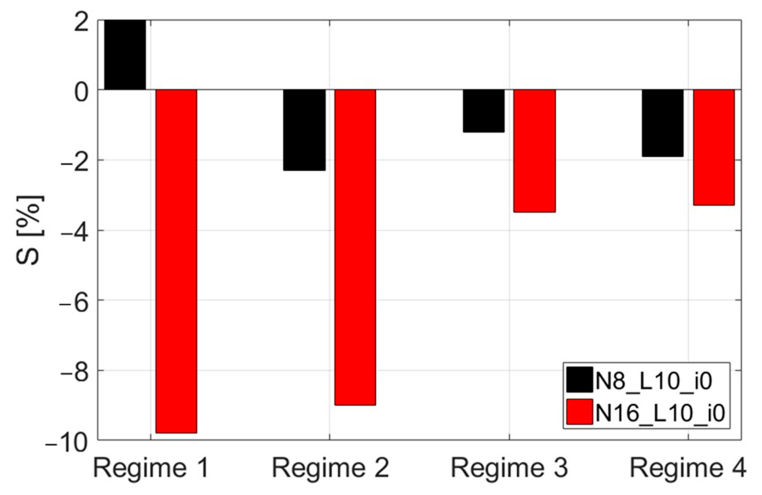
The specific fuel consumption for the chevron nozzle cases present decreases comparing with the reference nozzle.
The following
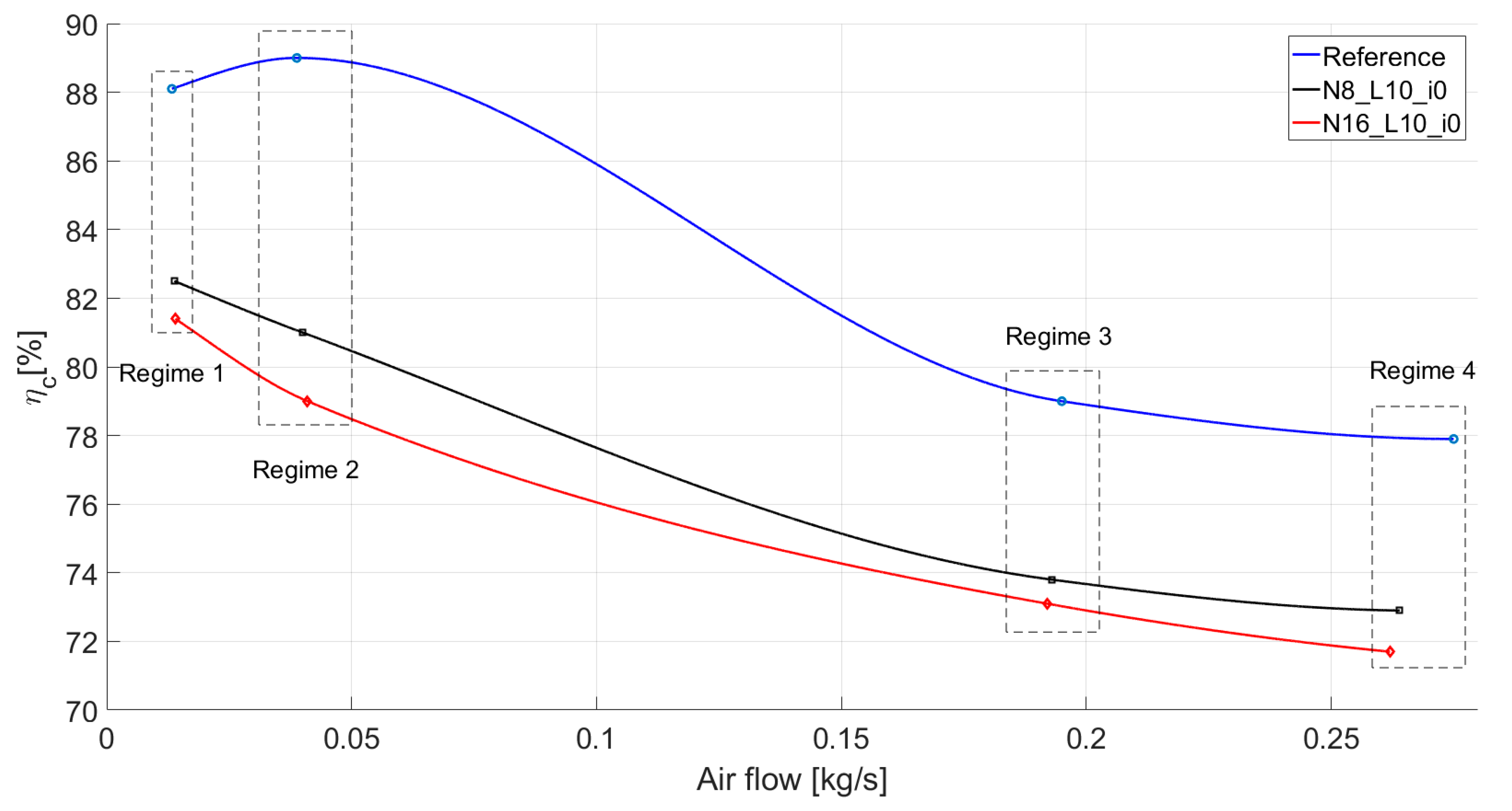
Figure 11 and
Figure 12 present the most important parameters that dictate the micro turbojet engine performances for the three tested chevrons.
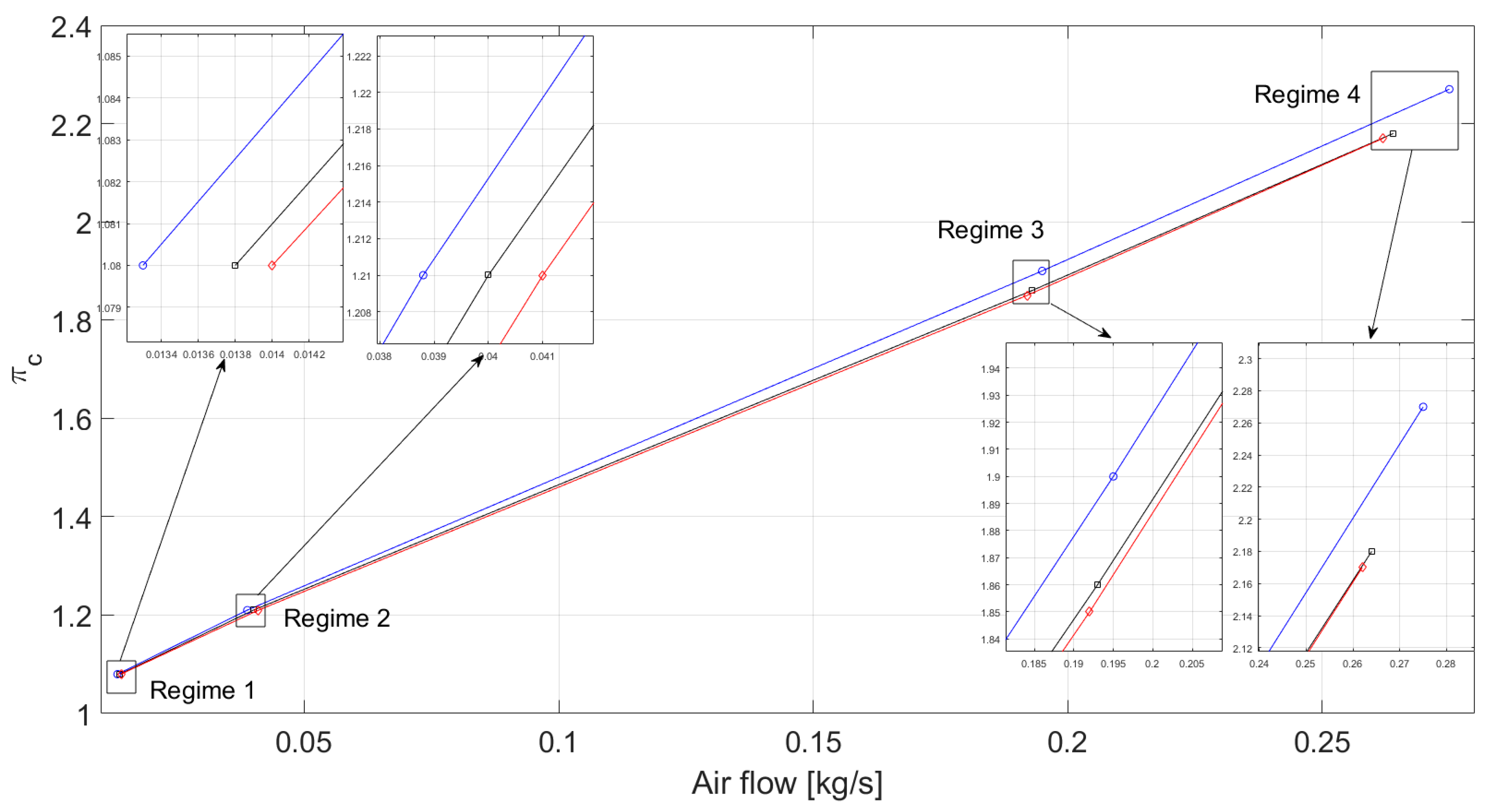
Analyzing
Figure 11, it can be observed that the work lines of the compressor for the chevron nozzles have been slightly modified, but the surge line was not overpass, without endangering the integrity of the engine.
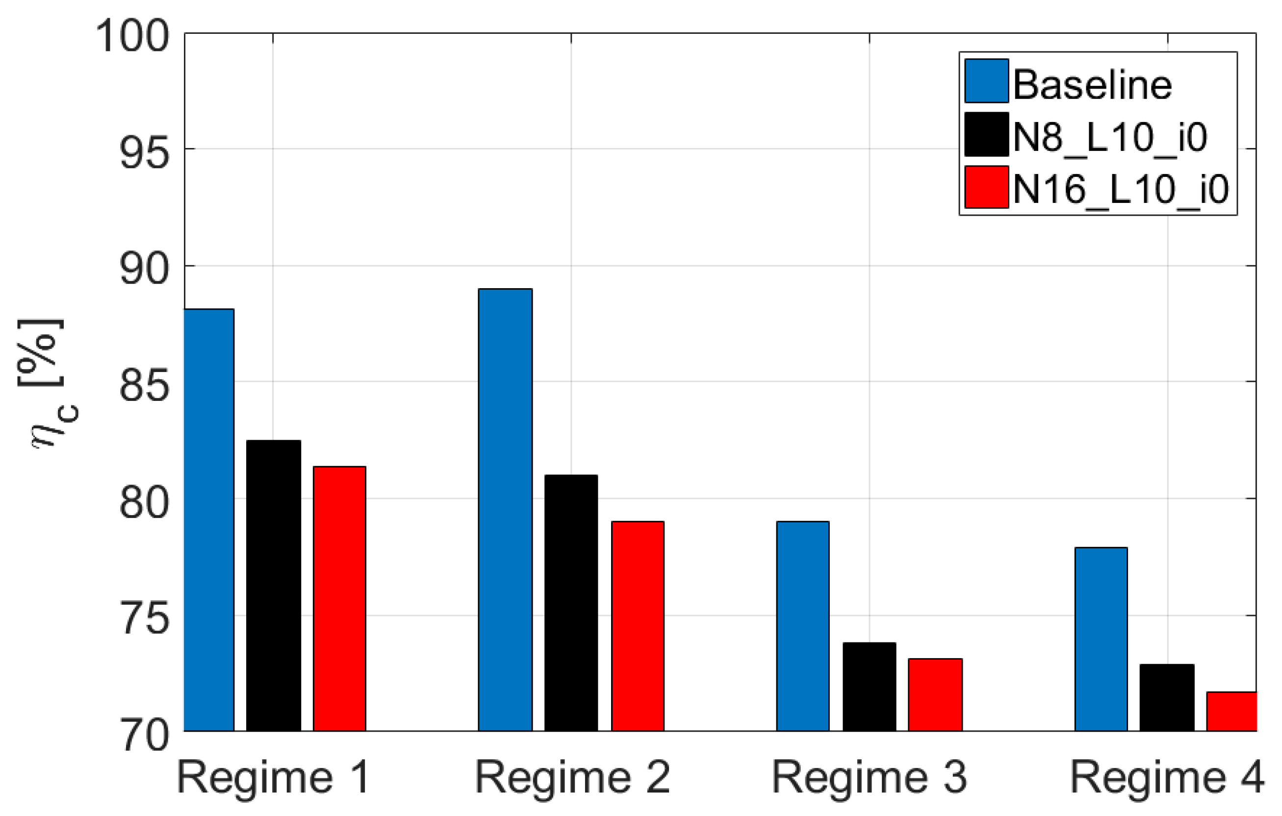
Assessing the variation of efficiency characteristics of the compressor, depending on the air flow, it can be observed that, at the same regime, the compressor efficiency drops by increasing the number of chevrons.
For the entire engine round, its operation did not present any problem for all tested nozzles; the only drawback is the force loss for chevron cases. Modification of the exhaust section, by manufacturing the chevrons, has led to growth of the internal resistances in the engine. This was reflected in the fact that the compressor had to generate greater mechanical work, which led to an increase of the temperature of air after the compressor.
Because the control law of the engine is based on constant speed, during the nozzle testing, the engine tried to maintain the same power for the compressor, but because the mechanical work on the compressor increased, results of the mechanical work on turbine increased too.
Growing mechanical work on the turbine can be produced by increasing the temperature in front of the turbine, which is produced by increasing the fuel flow. A bigger fuel flow will lead to a higher speed, which is contrary with the control law, so the only possibility to increase the mechanical work on the turbine, without increasing the speed, was to reduce the fuel flow and implicitly reduce the temperature in front of the turbine. Decreasing the temperature in front of the turbine leads to a temperature reduction after the turbine, which will lead to a decrease in the gas speed out of the engine. The reduction in the intake airflow, fuel flow, and the gas speed explains the reduction of the thrust force.
6. Conclusions
The main conclusion of this paper is related to the overall noise reduction of 2–3 dB for the configurations with chevron nozzles, which is obtained only at high-speed regimes. The noise reduction of the chevrons is obtained through a better mixture film between the jet gases and the air from the atmosphere. The FFT analysis of the acoustic signals highlighted that the noise reduction generated by the chevrons has broadband characteristics. The vibration spectra highlighted that the main vibration source corresponds to the engine speed for each regime, and there was not any identified rule of the vibration variation related to the engine speed. The replacement of the reference nozzle with chevron nozzles does not produce any significant increase in the vibration levels. During the chevrons’ testing, the vibration levels were slightly increased but without putting the engine function in danger.
Regarding the engine performances, modification of the nozzle, by cutting the chevrons, leads to a reduction in the propulsion force, especially for a nozzle with 16 chevrons.
In terms of engine traction force, the engine suffered losses up to 6% for regime 3 and, for the other regimes, around 4%. The losses were slightly higher for the configuration with N = 16 compared to N = 8. Regarding fuel consumption, a 6–7% decrease at the maximum regime was recorded.
The main conclusion is that the noise reduction of almost 3 dB comes with a penalty to the engine performance.
The future research will focus on optimization of the chevrons’ design by finding optimum concepts in terms of noise reduction and performances losses without modifying the work line of the compressor and by testing the new optimized chevron designs in an anechoic room with multiple microphones in polar configuration.


