Article

A Novel Exact Analytical Solution Based on Kloss Equation towards Accurate Speed-Time Characteristics Modeling of Induction Machines during No-Load Direct Startups

1
Faculty of Electrical Engineering, University of Montenegro, Dzordza Vasingtona, 81000 Podgorica, Montenegro
2
College of Engineering, University of Business and Technology (UBT), Jeddah 23846, Saudi Arabia
3
Faculty of Technical Sciences, University of Kragujevac, 32000 Čačak, Serbia
4
Department of Electrical Engineering, College of Engineering, Taif University, Taif 21944, Saudi Arabia
5
Department of Electrical Engineering and Electronics, Valley Higher Institute of Engineering and Technology, Science Valley Academy, Al-Qalyubia 44971, Egypt
*
Author to whom correspondence should be addressed.
Appl. Sci. 2021, 11(11), 5102; https://doi.org/10.3390/app11115102
Submission received: 2 April 2021 / Revised: 21 May 2021 / Accepted: 27 May 2021 / Published: 31 May 2021
(This article belongs to the Special Issue Modeling, Design and Control of Electric Machines)

Abstract

:
The acceleration time of induction machines (IMs) is essential for proper protection-relay settings of the machine to prevent voltage sags in local power areas. In this paper, mathematical modeling of IMs’ speed-time characteristics during no-load direct startup has been presented. Unlike the approaches presented in the literature, the proposed approach includes the bearing losses, in which two expressions of the speed-time characteristics of IMs during no-load direct startup are derived. The first expression was derived based on the Kloss equation used for representing the torque, and the second expression was derived based on the torque expression determined from the Thevenin equivalent circuit of the machine. The derived expressions’ accuracy was validated using laboratory measurement and computer simulation approaches. The results obtained show a good agreement between the measured and simulated speed-time characteristics of two IMs. Finally, the proposed formulations can provide a simple analytical base to enable accurate IM modeling.

1. Introduction

Induction machine (IMs) are the oldest electrical machines, but they are widely used in industrial and domestic operations. This machine’s fundamental problem is its starting period, as starting this type represents a set of processes that occur during acceleration of the machine from zero speed to a specific speed (rated speed, no-load speed, or others) [1]. During IM direct startup, the rotor currents’ frequency depends on the rotor’s speed, and the machine’s stator currents are very high, i.e., higher than the rated current. Hence, analyzing the starting period of IMs is necessary for the protection and stability issues.
In the literature, many IMs’ starting methods can be found. They can be classified into two broad categories—conventional motor starters and modern power electronic-based devices to start the machine. The first category involves methods that rely on the classic regulation of the supply voltage or practices using additional equipment [2,3]. The direct-on-line (DOL) method belongs to this category, in which it can be realized with or without the reduced voltage technique [4], the variable rotor resistance method [3], the shunting of the stator and rotor windings [4], the star-delta method [5,6] and the usage of auto-transformers [6,7]. The second category involves methods that rely on power electronics devices or soft starters [2]. The advantages and disadvantages of these methods are comprehensively discussed in [7]. The most traditional method for IM starting is the DOL method [8,9]. However, the DOL method is much more beneficial in parameters estimation of IMs [10,11,12].
In this regard, speed-time characteristics calculation during IM startup is essential for the secure operation power distribution network. Observing the research works investigating the IM starting process analysis, it can be noted that this research field is vital from two perspectives.
The first perspective is that the IM starting process can benefit parameter determination either with a direct startup [8,9] or acceleration [12,13] or acceleration-deceleration tests [14]. Many research works were dedicated to estimating motor parameters under different conditions. For instance, Yadav et al. in [15] have recognized IM’s parameters using limited and non-intrusive observations of input voltages, stator currents, and the rotor speed and convex optimization. Babau et al. in [14] proposed a complete parameter identification procedure of large IMs from no-load acceleration-deceleration tests. Kojooyan et al. in [12] have used the instantaneous power of a free acceleration test for squirrel-cage IM parameters estimation, and Ćalasan et al. in [16] proposed a hybrid simulated annealing evaporation–rate water cycle algorithm [17] for parameter estimation of single-cage and double-cage IMs models.
The second perspective is that the IM starting process duration is significant for proper machine protection-relay settings, avoiding overheating and poor power quality issues [1,18]. For instance, starting a large IM can cause substantial voltage sags in industrial areas, adversely impacting the system’s sensitive and local loads (especially lightning and personal computers (PC) and power quality [19]. The no-load starting time defines the value of the maximum starting time, which in turn determines the proper current relay action (or delay time determination) for IM protection and stable and safe operation. For that reason, several manufacturers provide equations to determine torque and power and their relation with starting time [20]. The technical report of low-voltage IMs is presented in [21], and the equations, which define three-phase IMs and suggestions for the coordination of protective devices, are given in [22].
As the machine accelerates, the starting currents decrease. The critical period of time in such a startup period is the critical voltage-sag removal time (CVSRT). CVSRT reflects a duration from the launch of voltage sags to the instant when an IM’s speed becomes equal to the rated or other predefined value. CVSRT can be determined in several manners [18]. First, it can be measured by time-domain dynamic simulation that requires a complete set of IM parameters and an appropriate program package and mathematical equations set. This approach is quite monotonous since the simulation should be repeated until the correct CVSRT is found. Second, CVRST can be measured using finite element methods (FEMs). However, these methods require many machine data, including complete machine geometric data. Therefore, it is not a practical and hand-useful method, particularly for older machines [7,8,9]. Third, CVRST can be determined using an analytical solution of the speed-time characteristics curve. These approaches are beneficial as they give simple expressions [13,23], and can be calculated using different program packages (such as Matlab, Maple, and others).
In the literature, Aree, in [9], has presented an analytical formula for starting time calculation of medium- and high-voltage induction motors under conventional starter methods. However, to control the solution using his suggested expression, Aree has used some additional parameters, and therefore the developed formulation is not entirely mathematically correct. Likewise, Calasan has introduced different solutions for this problem in [8,20,24]. He developed an invertible speed-time characteristics curve during machine startup using Kloss expression for the machine’s torque representation [24]. In [20], invertible expressions were derived using the machine torque’s full expression based on the Thevenin theorem and the machine’s single-cage equivalent circuit. An analytical solution for IM acceleration and maximum acceleration value was presented in [24]. However, the expressions given did not include the bearing losses in the suggested models; therefore, IMs’ speed-time characteristics modeling during no-load direct startups were not accurate enough. The IM starting time and speed–time curves can also be determined using numerical time-domain computation (NTDC) approaches [13]. NTDC methods assume representing the machine with a set of differential equations for electrical machine circuits, and mechanical motion. However, to describe the IM dynamic’s behavior, numerical integration techniques should be used. NTDC can be implemented in specific program packages (for instance, PSpice, Matlab, Mathematica, etc.). However, these methods are slow, time-consuming, and require the usage of special software.
This paper aims to present a novel mathematical expression for speed-time characteristics representation during DOL machine starting, including the bearing losses to accurately formulate IMs’ speed-time characteristics modeling during no-load direct startups. In this regard, two expressions of the speed-time characteristics of IMs during no-load direct startup are derived. The first expression was derived based on the Kloss equation used for representing the torque, and the second expression was derived based on the torque expression determined from the Thevenin equivalent circuit of the machine.
The goal is also to compare the speed-time characteristics obtained by using the proposed expressions with the results obtained using the expressions known in the literature. The derived expressions’ accuracy was validated using laboratory measurement and computer simulation approaches. The results obtained show that the proposed formulations enable accurate machine modeling under the worst condition—during direct startup. It should be mentioned that the proposed method did not address saturation of the magnetic circuit and current displacement in the rotor bars, as the IEEE standard T-equivalent scheme for IM machine parameters estimation was used. These phenomena significantly impact torque-time and current-time curves, which may change the engine startup time. But the integral equations that need to be solved to calculate the startup time will become more difficult and complex.
The rest of the paper is organized into few sections. An overview of the known expressions for speed-time characteristics during machine startup is given in the second section (Section 2). The two-novel expressions for IMs’ speed-time characteristics during no-load direct startup are presented in the same section. The simulation results are illustrated in the third section (Section 3). Further, experimental verification of the proposed equations is presented in Section 4, while the concluding remarks are given in Section 5.

2. Existing Methods and the Novel Expressions Proposed for Speed-Time Curve Representation during No-Load Direct Startup of IMs

A short review of the previously published papers concerning the IM’s speed-time characteristics during direct startup is given in this section. In addition, the novel expressions proposed for the mentioned characteristics are presented.

2.1. Aree’s Method

In [9], Aree has presented a method for formulating the IM’s no-load direct startup. In the mentioned paper, many simulations and experimental results for different starting strategies were introduced.
For the description of the speed-time characteristics, Aree has derived the following expression for time t:
t = π J 30 j k j log ( n n r j ξ n l o n r j )
where n is the speed of rotation, nlo is the lower speed value, nrj, and kj are coefficients that depend on load and machine data, and J is the moment of inertia. However, to enable stability of the solution, Aree has added a correction factor named ξ that does not have any physical representation.

2.2. Calasan’s Method

Calasan have described two invertible expressions for the speed-time curve representation of IM during direct startup. The following expression was derived in [20]:
t = J ω s 2 U T 2 R 2 ( ( R T 2 + ( X T + X 2 ) 2 ) 2 ( 1 s 2 ) + 2 R T R 2 ( 1 s ) R 2 2 log ( s ) )
where s is the machine’s slip, RT and XT and UT represent the Thevenin equivalent resistance and reactance and voltage of the IM’s equivalent circuit, respectively.
On the other side, in [24], Calasan has proposed the following expression to represent the IM’s speed-time characteristics during direct startup.
t = J ω s 2 M b r ( 1 s 2 2 s b r s b r log ( s ) )
where Mbr is the maximum machine torque, and sbr is its corresponding slip. Details about the parameters given in Equations (2) and (3) are presented in Appendix A.
However, it should be noted that for both derived expressions, the bearing losses were ignored.

2.3. Proposed Expressions for Speed-Time Characteristics Representation, with Bearing Losses

2.3.1. The First Expression

The basic mechanical equation that represents rotation of any IM is given based on Newton’s second law of motion as follows:
J d ω d t = M e m M f r i c t i o n
The electromagnetic torque (Mem) can be expressed in terms of the Kloss equation. In addition, the torque due to friction (Mfriction) can be represented using the speed of rotation.
The time increment (dt) can be calculated as follows:
d t = J ω s s 2 + J ω s s b r 2 B ω s s 3 B ω s s 2 + ( 2 M b r s b r + B ω s s b r 2 ) s B ω s s b r 2 d s
Therefore, the total startup time up to realize a certain speed is obtained as follows:
t = 1 s J ω s s 2 + J ω s s b r 2 B ω s s 3 B ω s s 2 + ( 2 M b r s b r + B ω s s b r 2 ) s B ω s s b r 2 d s
Equation (6) can be written in a more general mathematical form as follows:
t = 1 s α 1 s 2 + α 2 s + α 3 α 4 s 3 + α 5 s 2 + α 6 s + α 7 d s
so that:
α 1 = J ω s , α 2 = 0 , α 3 = J ω s s b r 2 , α 4 = B ω s , α 5 = α 4 , α 6 = 2 M b r s b r + B ω s s b r 2 , and α 7 = B ω s s b r 2
The previous integral expression can be easily solved for any IM with known appropriate parameters. Firstly, one can formulate the solution expression as follows, in which the unknown coefficients k1, k2, k3, s1, r1, r2, and r3 should be determined.
α 1 s 2 + α 2 s + α 3 α 4 s 3 + α 5 s 2 + α 6 s + α 7 = k 1 s s 1 + k 2 s + k 3 r 1 s 2 + r 2 s + r 3
The coefficient s1 represents a real pole of the equation; thus:
α 4 s 3 + α 5 s 2 + α 6 s + α 7 = 0
The coefficients r1, r2, and r3 are determined by dividing the polynomial α 4 s 3 + α 5 s 2 + α 6 s + α 7 with the polynomial s s 1 .
The other coefficients can be defined as follows:
k 1 ( r 1 s 2 + r 2 s + r 3 ) + ( s s 1 ) ( k 2 s + k 3 ) = α 1 s 2 + α 2 s + α 3
Then, a system of equations is formed as follows:
[ k 1 k 2 k 3 ] = [ r 1 1 0 r 2 x 1 1 r 3 0 x 1 ] 1 [ α 1 α 2 α 3 ]
Hence, the time expression is obtained by solving the following integrals. Thus:
t = 1 s k 1 s s 1 d s + 1 s k 2 s + k 3 r 1 s 2 + r 2 s + r 3 d s
Solution of Equation (13) is given as follows:
t = I 1 + I 2 + I 3 , I 1 = k 1 log ( 1 s 1 ) k 1 log ( s s 1 ) , I 2 = 2 k 3 4 r 3 r 1 r 2 2 ( tan 1 ( 2 r 1 + r 2 ) 4 r 3 r 1 r 2 2 tan 1 ( 2 r 1 s + r 2 ) 4 r 3 r 1 r 2 2 ) , I 3 = k 2 ( 1 2 r 1 ( log ( r 1 + r 2 + r 3 ) log ( r 1 s 2 + r 2 s + r 3 ) ) ) r 2 2 r 1 I 2 k 3 .

2.3.2. The Second Expression

The second approach for the IM’s speed-time curve characteristics during the no-load direct startup is based on using the machine torque expression derived from the Thevenin equivalent circuit. Hence, the mechanical equation of the IM’s rotation is given as follows:
J ω s d s d t = ( 3 ( U T 3 ) 2 ω s ( R 2 s ( R T + R 2 s ) 2 + ( X T + X 2 ) 2 ) B ω s ( 1 s ) )
In such a case, Equation (15) can be rewritten in the form of Equation (7), so that:
α 1 = J ω s ( R T 2 + ( X T + X 2 ) 2 ) , α 2 = 2 R T R 2 J ω s , α 3 = J ω s R 2 2 , α 4 = B ω s ( R T 2 + ( X T + X 2 ) 2 ) , α 5 = B ω s ( 2 R T R 2 R T 2 ( X T + X 2 ) 2 ) , α 6 = U T 2 R 2 ω s + B ω s ( R 2 2 2 R T R 2 ) , and α 7 = B ω s ( R T 2 + ( X T + X 2 ) 2 ) .
After that, the procedure to determine the starting time will be similar to the first expression’s previously described methodology.

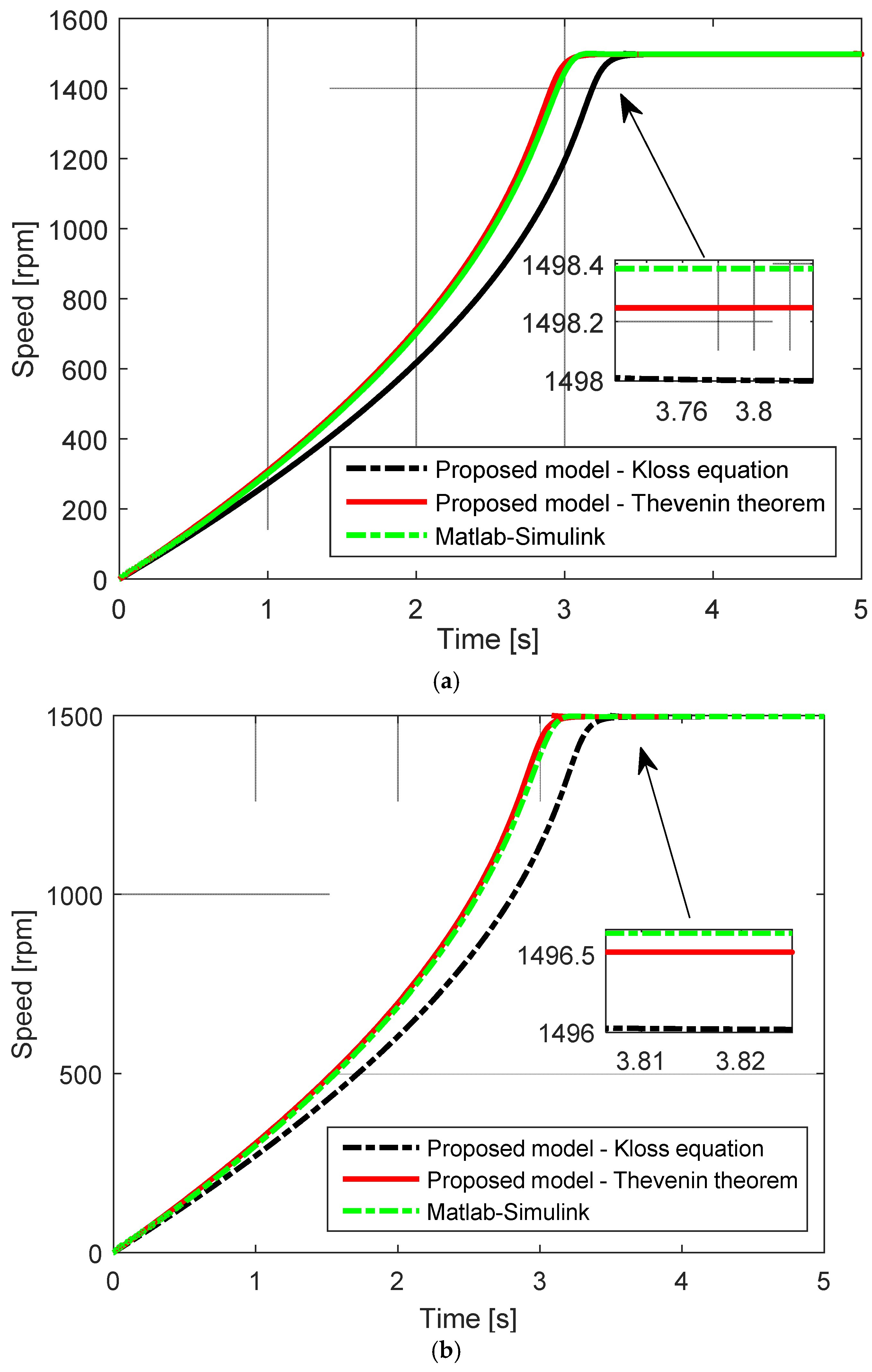
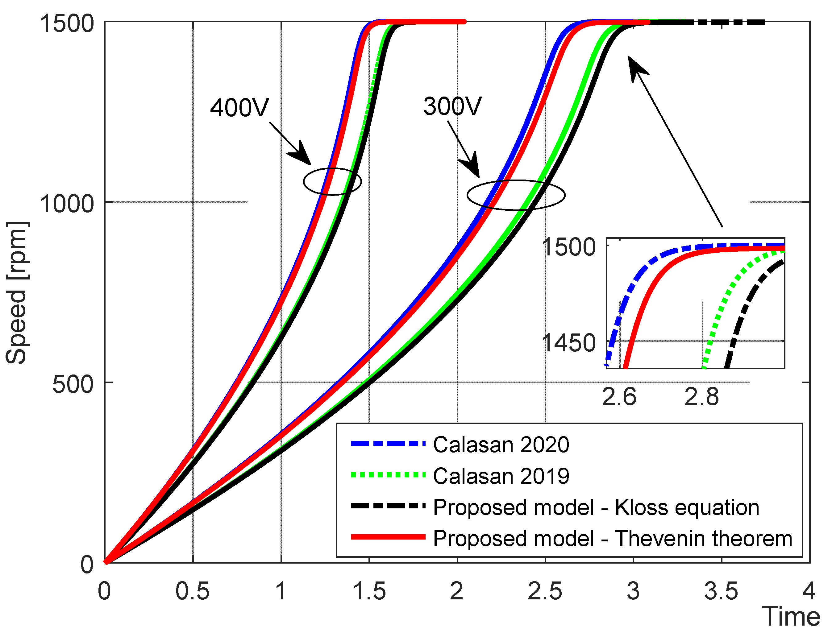
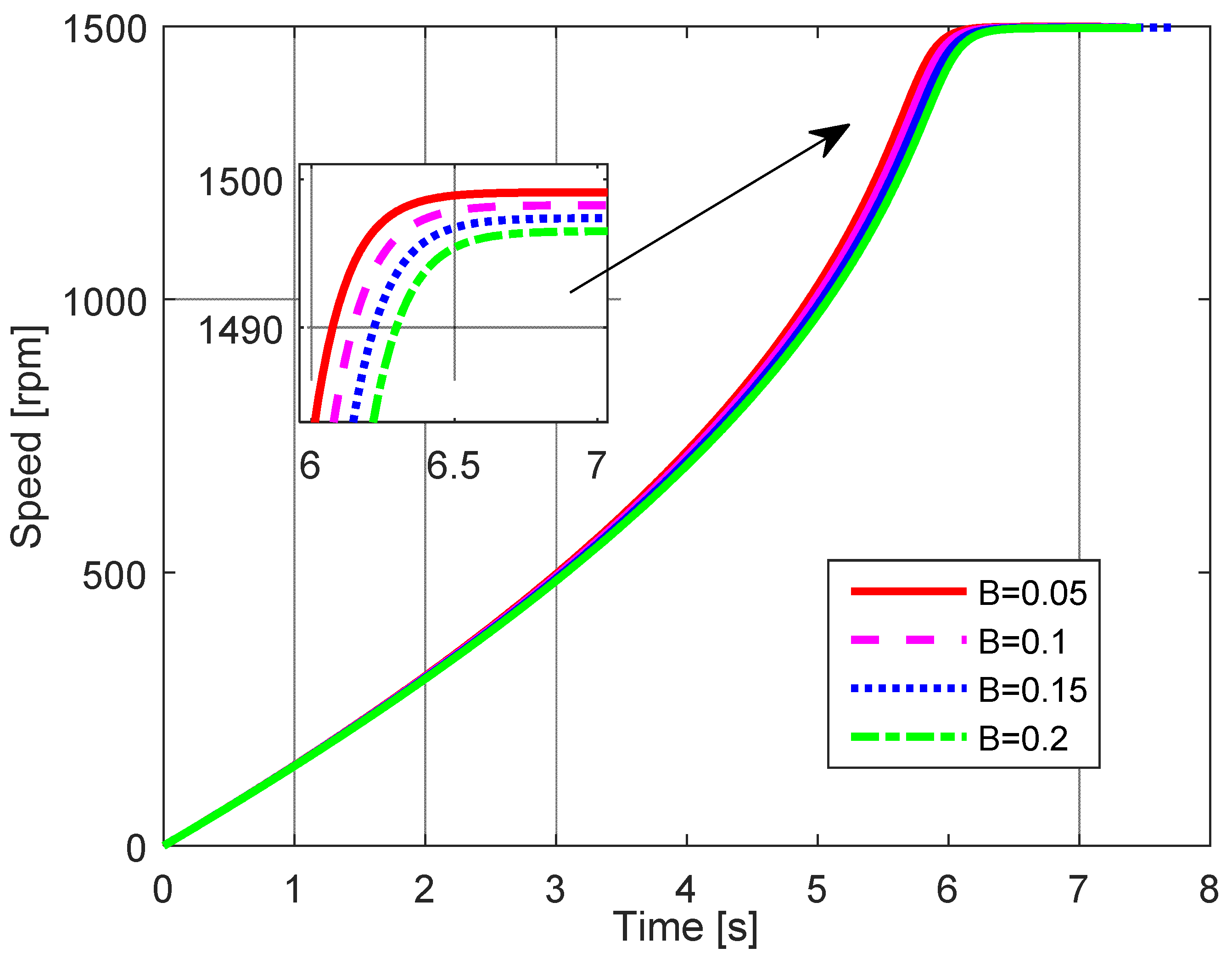
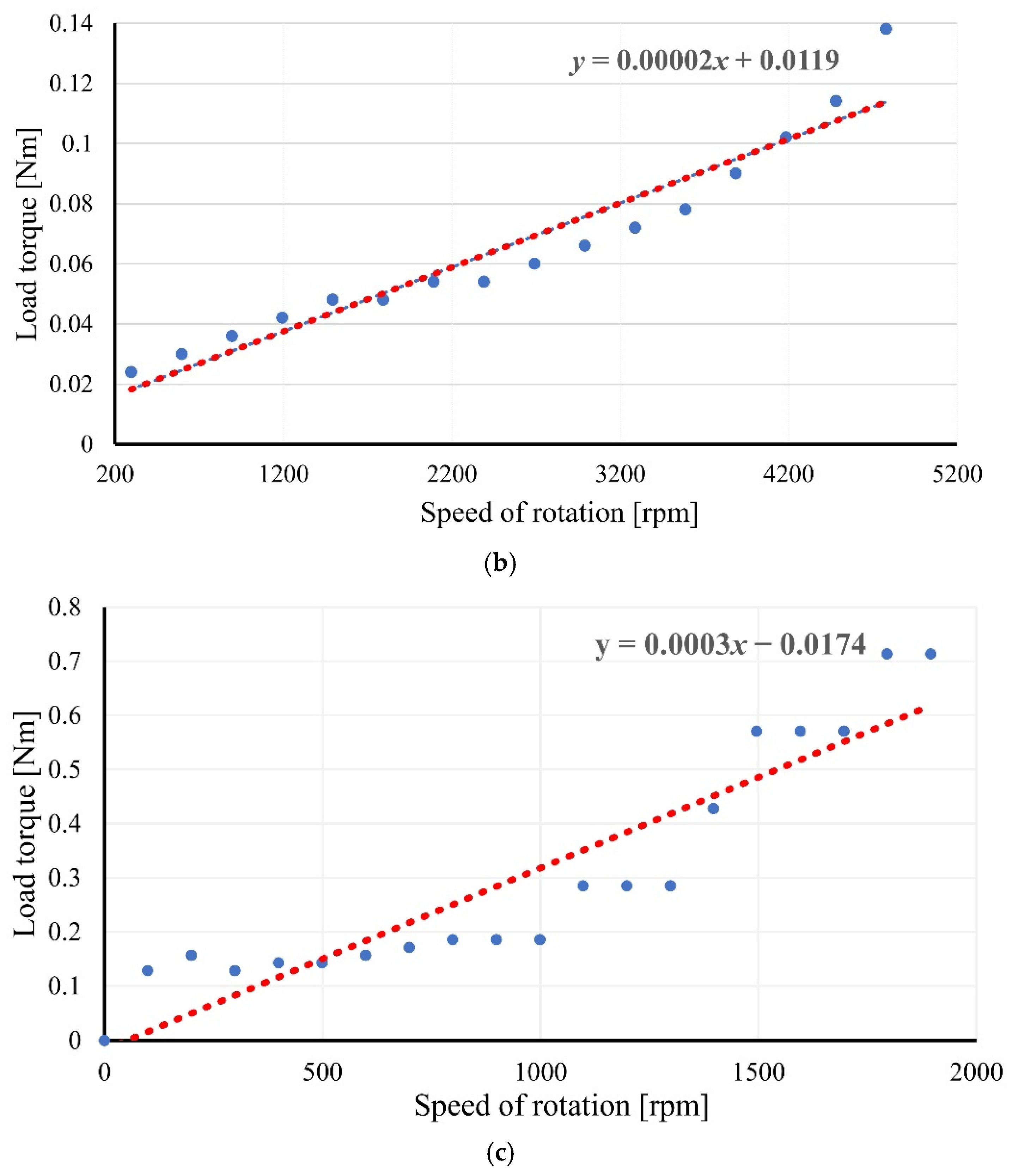
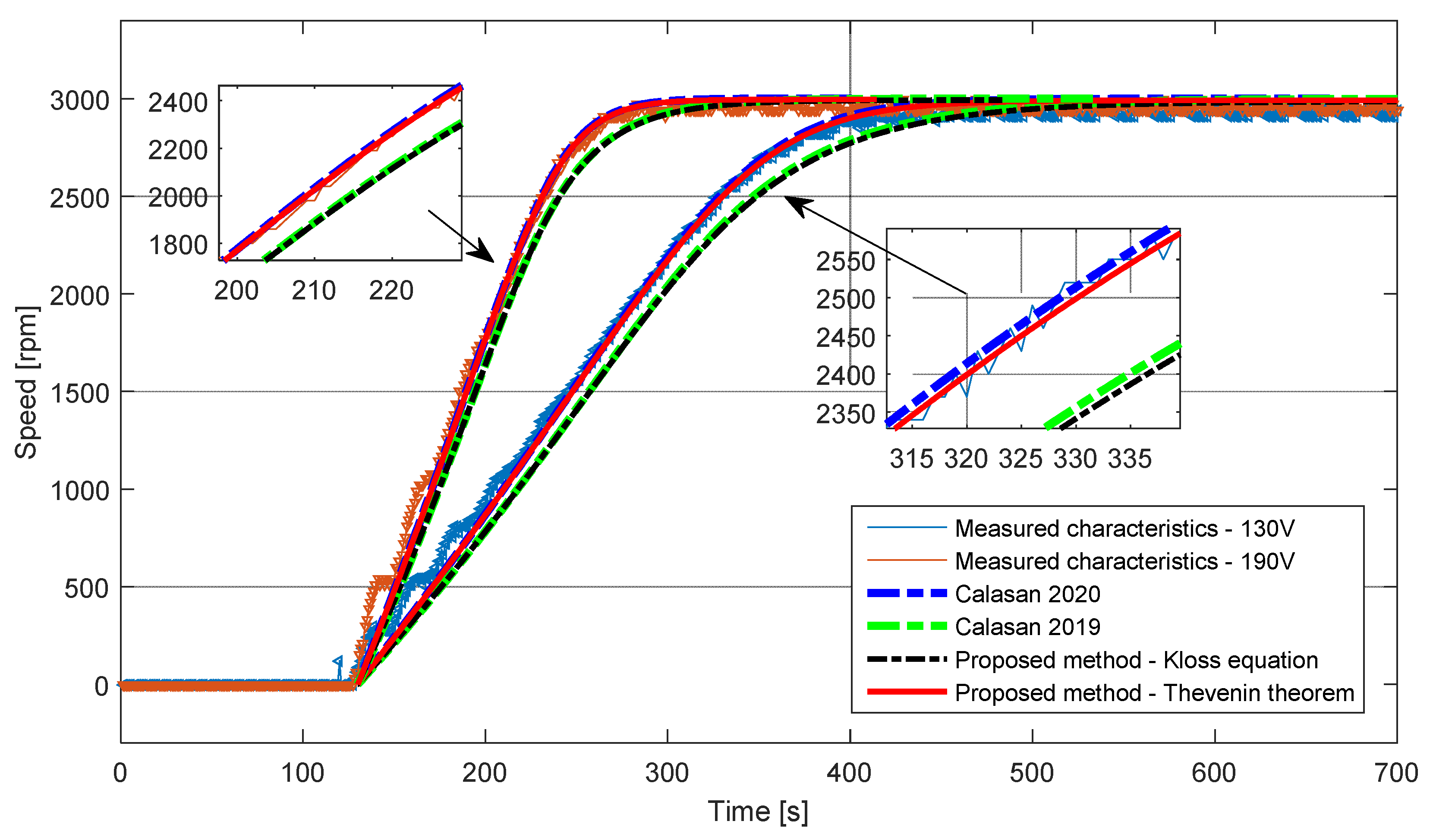
3. Simulation Results and Analyses

To demonstrate the accuracy of the proposed expression for speed-time characteristics determination of an IM during a direct startup, we studied an IM whose parameters are given in Table A1 in the Appendix B. We have also considered the Matlab/Simulink model for speed-time curve determination during direct startup described in [20,24].
For the analyzed machine, the simulation speed-time curve during direct startup, determined for different bearing loss values (B = 0.1 and B = 0.2), is explored in Figure 1. The results obtained using the proposed expressions are compared with the model results in the same figure. As can be seen, the proposed expression for the speed-time curve during no-load direct startup based on the Thevenin theorem is very close to the results obtained by the Simulink model. Furthermore, for the mentioned curves, the settling time and the rise time are almost identical.
On the other side, the Kloss equation’s proposed expression demonstrates some mismatching with the previously mentioned results. The impact of the variation of the supply voltage on the speed-time curve during the IM’s no-load direct startup is presented in Figure 2. The results obtained using the earlier expressions in [8,20,24] for IM speed-time curve determination are also shown in Figure 2.
It can be seen that the bearing loss has an impact on the speed-time characteristics, as demonstrated in Figure 3. As the bearing loss’s value increases, its effect on the mentioned curves will be considerable and visible. Furthermore, the higher values of bearing loss led to a rise in the machine’s take-off time.

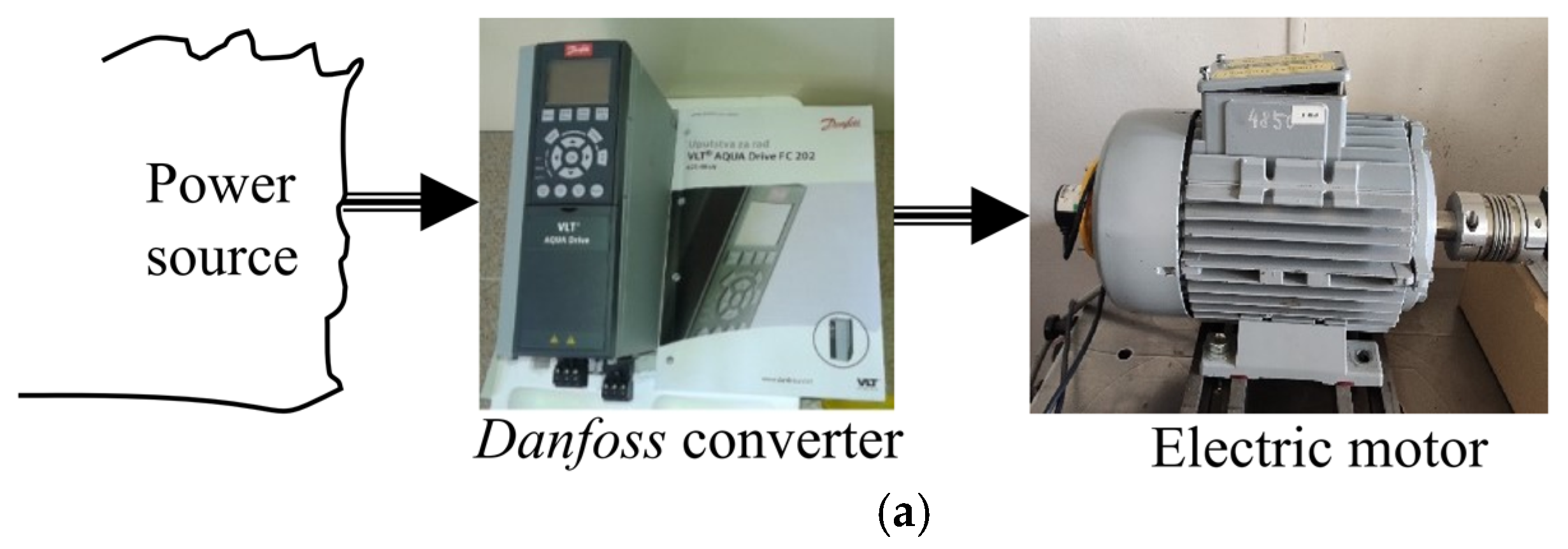
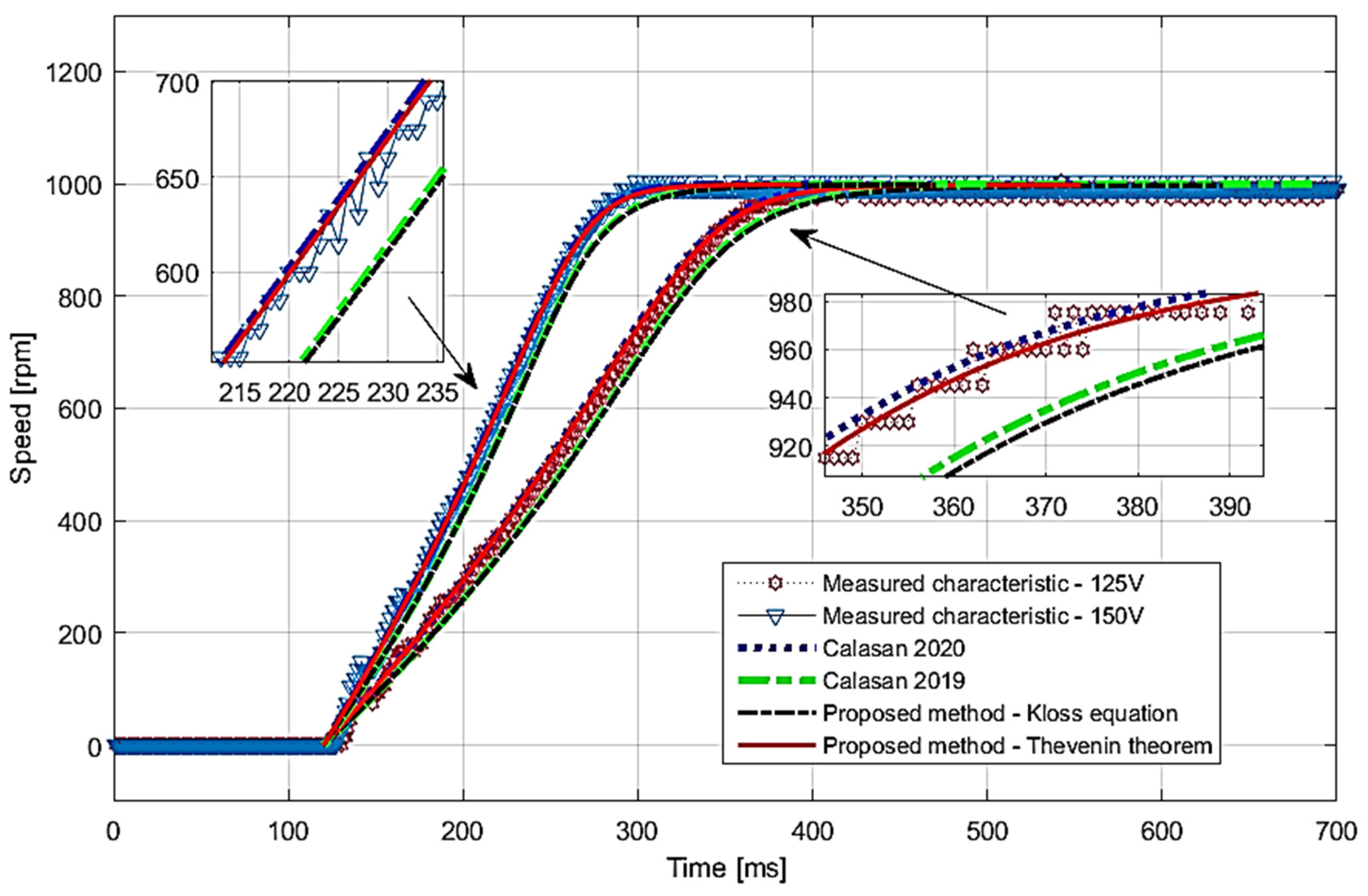
4. Experimental Results

The performance of two different IMs (SIEBER LS71, denoted as IM#1 and ATB SEVER 1.ZK90 L-6, denoted as IM#2), with the parameters given in Table A2 in the Appendix B, has been investigated to confirm the accuracy of the derived expressions.
The experimental setup for testing these machines was realized in the Laboratory for Electric Machines and Drives at the Faculty of Technical Science, University of Kragujevac, Serbia. First, the initial tests (open-circuit and short circuit-tests) have been carried out to determine the equivalent motor parameters, and the obtained values of the equivalent circuit data are presented in Table 1.
Second, to determine the friction torque and bearing losses, both motors were powered using a Danfoss frequency converter. A resistance-current compensation was carried on the frequency converter; therefore, the torque was constant for all frequencies, allowing parallel mechanical (i.e., torque-speed) characteristics during recording. Further, the motor load (directly proportional to the friction torque) at different speeds was determined using the triangle similarity rule. With the resistance-current compensation enabled at voltage/frequency (U/f) control (and slip compensation disabled), one can roughly assume that all the machine characteristics (the torque as a function in the speed) would be parallel as frequency changes in a speed frame of interest. In that case, any difference in the speed (with an unloaded machine) will reflect the friction torque. Thus, the small changes in speeds at different frequencies have been recorded, and the friction torque was calculated in a wide-speed region. B’s value was determined from the value of this torque (Mfriction = B*n), as shown in Figure 4 for both machines. Catalog data of the value of the moment of inertia was already known for both motors.
It should be noted that the friction torque is not linear with speed, especially at low speeds. Stribeck friction cannot be neglected at low speeds. However, in the literature, the friction torque is usually linear with speed as it mainly reflects viscous friction in bearings. This approximation was made in this work, and the friction torque was considered viscous torque because it would be hard to experimentally determine the Stribeck friction component that exists only at low speed. Another way to determine the friction torque is to form the speed response characteristic with a switched-off motor at high speed. However, complex mathematical investigations will be needed to model the non-linear region accurately.
A precise recording of the two analyzed machines’ run-up was performed. It was realized by an encoder on the motor shaft and a digital signal processor (DSP) that collects data at 100 ms. The speed recording for IM#1 and IM#2 was performed using different voltage values—130 V and 190 V for IM#1 and 125 V and 150 V, for IM#2. All the records were identified where the motor is turned on at 100 ms.
The measured and the simulated results are presented in Figure 5 and Figure 6, for both machines. The perfect agreement between all simulated and measured results is apparent.
The methods presented in [8] and the proposed method based on the Kloss equation provide the most considerable deviations from the measured values. The main reason is that the Kloss equation does not represent an ideal approximation for a real torque-speed curve. However, the proposed method based on the Thevenin theorem gives the best matching results with the experimental results. This conclusion is identical to the conclusion derived from the previous simulation results. Therefore, it can be concluded that the proposed expressions in this work are accurate; they were derived without any mathematical assumption, and they enable obtaining results that are in perfect agreement with the measured results. The derived expressions can benefit IM protection device settings or test the duration of voltage sags in power networks caused by IM starting or similar.

5. Conclusions and Future Works

In this paper, exact mathematical expressions towards accurate speed–time characteristics IMs modeling during no-load direct startups were derived. The derived expressions were based on the Kloss equation and electromagnetic torque expression derived from the Thevenin single-cage equivalent circuit, and unlike the literature, both of them include the bearing losses. Both expressions are novel and are not presented before in the literature.
The speed–time characteristics during direct startup for different IMs (in respect to power) obtained using the proposed methods are compared with the characteristics obtained using the corresponding expressions presented in the literature. The simulation and experimental results observed validate the figured-out conclusions about the accuracy of derived expressions.
The small differences in the calculated acceleration times are due to the fact that the investigated machine sizes are small. However, for higher machines power, the differences will be higher. Although the differences are small, the mathematical relation proposed in this work is accurate as they include bearing losses, simple and straightforward. In addition, the proposed expressions can generally be applicable for all IMs, for old and new machines, regardless of the machine power or voltage level.
The derived speed–time dependence can be used for different engineering applications—protective device settings in power networks with an IM, settings phase current protection relay actions of IMs’, testings of the impact of IM starting on sensitive loads, and others.
In future works, much attention will be paid to calculating the loaded IM’s speed-time curve. In such a case, starting the loaded IM with ventilation characteristics will be investigated. In addition, a speed response characteristic with a switched-off motor at high speed will be addressed to accurately determine the friction torque. Besides, the nonlinear saturation of the magnetic circuit and current displacement in the rotor bars will be investigated and solved as these phenomena significantly impact torque-time and current-time curves, which may change the engine startup time.

Author Contributions

M.Ć. designed the problem under study; M.Ć., M.A., M.R., N.K., performed the simulations and obtained the results; M.Ć., B.A. and S.H.E.A.A. analyzed the obtained results; M.Ć. wrote the paper, which was further reviewed by S.H.E.A.A., M.A., M.R., N.K. and B.A. All authors have read and agreed to the published version of the manuscript.

Funding

The authors would like to acknowledge the financial support received from Taif University Researchers Supporting Project Number (TURSP-2020/278), Taif University, Taif, Saudi Arabia.

Institutional Review Board Statement

Not applicable.

Informed Consent Statement

Not applicable.

Data Availability Statement

The data presented in this study are available on request from the corresponding author. The data are not publicly available due to their large size.

Conflicts of Interest

The authors declare no conflict of interest.

Abbreviations

CVSRTCritical voltage-sag removal time
DOLDirect-on-line
DSPDigital signal processor
FEMsFinite element methods
IMsInduction machines
PCPersonal computer
CVSRTCritical voltage-sag removal time
DOLDirect-on-line
DSPDigital signal processor
FEMsFinite element methods
IMsInduction machines
PCPersonal computer

Nomenclature

BBearing loss
dtTime increment
JMoment of inertia (kgm2)
MIM’s torque
MbrMaximum machine torque
MemElectromagnetic torque
MfrictionTorque due to friction
nSpeed of rotation
nloLower speed value
nrj, and kjCoefficients that depend on load and machine data
nsSynchronous speed
RT and XTThevenin equivalent resistance and reactance of the IM’s equivalent circuit
R1Stator resistance
R2Rotor resistance referred to the stator side
sSlip of the machine
sbrCorresponding slip at the maximum machine torque
tTime to represent the IM’s speed-time curve during direct startup
UTThevenin equivalent voltage
USupply line-to-line voltage
X1Stator leakage reactance
X2Rotor leakage reactance referred to the stator side
XmMagnetizing reactance
ξAree’s correction factor

Appendix A

In Equation (2), RT and XT are given as follows:
R T = R 1 X m 2 R 1 2 + ( X 1 + X m ) 2 X T = X m R 1 2 + X 1 2 X m + X 1 X m 2 R 1 2 + ( X 1 + X m ) 2
R1 denotes the stator resistance, R2 denotes the rotor resistance referred to the stator side, X1 denotes the stator leakage reactance, X2 denotes the rotor leakage reactance referred to the stator side, and Xm represents the magnetizing reactance. In addition, UT represents the Thevenin equivalent voltage ( U T = X m X 1 + X m U ), where U is the supply line-to-line voltage,   ω s = 2 π n s 60 and ns is the synchronous speed. The expression was derived by observing the IM’s Thevenin equivalent circuit and formulating the IM’s torque (M), as follows:
M = 3 ( U T 3 ) 2 ω s ( R 2 s ( R T + R 2 s ) 2 + ( X T + X 2 ) 2 )
In Equation (3), Mbr and sbr can be calculated in the following manner:
M b r = 3 ( U T 3 ) 2 ω s ( X T + X 2 ( R T + X T + X 2 ) 2 + ( X T + X 2 ) 2 ) s b r = R 2 R T 2 + ( X T + X 2 ) 2
This expression was based on the Kloss equation for the machine’s torque representation. So that:
M = 2 M b r s s b r + s b r s

Appendix B

The investigated IM parameters are given in Table A1.
Table A1. Parameters of the considered induction machine.
ParametersValues
Pn (kW)37.3
Un (V)400
f (Hz)50
p2
R1 (Ω)0.028
R2 (Ω)0.081
X1 (Ω)0.0169
X2 (Ω)0.081
Xm (Ω)1.5156
Jn (kgm2) *4.9
R2 (Ω)0.081
* Rated value of the moment of inertia.
Data of the studied machines are given in Table A2.
Table A2. Data of the studied machines.
ParametersIM#1IM#2
Rated power (kW)0.3701.100
Rated voltage (V)230/400220/380
Rated current (A)1.7/16.0/3.5
Power factor0.830.7
Rated speed (rpm)2790920
Maximal torque (Nm)4.5/1.532.5/10.5
Breaking slip0.40.45
Rated torque (Nm)1.2611.42

References

  1. Bredthauer, J.; Struck, N. Starting of Large Medium Voltage Motors: Design, Protection, and Safety Aspects. IEEE Trans. Ind. Appl. 1995, 31, 1167–1176. [Google Scholar] [CrossRef]
  2. Pillay, K.; Nour, M.; Yang, K.H.; Harun, D.N.D.; Haw, L.K. Assessment and comparison of conventional motor starters and modern power electronic drives for induction motor starting characteristics. In Proceedings of the 2009 IEEE Symposium on Industrial Electronics and Applications, Kuala Lumpur, Malaysia, 4–6 October 2009; Volume 2, pp. 584–589. [Google Scholar]
  3. Hamouda, R.M.; Alolah, A.I.; Badr, M.A.; Abdel-halim, M.A. A comparative study on the starting methods of three phase wound-rotor induction motors—Part I. IEEE Trans. Energy Convers. 1999, 14, 918–922. [Google Scholar] [CrossRef]
  4. Badr, M.A.; Abdel-halim, M.A.; Alolah, A.I. A nonconventional method for fast starting of three phase wound-rotor induction motors. IEEE Trans. Energy Convers. 1996, 11, 701–707. [Google Scholar] [CrossRef]
  5. Banerjee, A.; Banerjee, A.; Rana, D.P.S.; Shubhanga, K.N. A study of starting methods for an induction motor using an arbitrary waveform generator. In Proceedings of the 2015 3rd International Conference on Advances in Electrical Engineering, Dhaka, Bangladesh, 17–19 December 2015; pp. 34–37. [Google Scholar]
  6. Goh, H.H.; Looi, M.S.; Kok, B.C. Comparison between Direct-On-Line, Star-Delta and Auto-transformer Induction Motor Starting Method in terms of Power Quality. Lect. Notes Eng. Comput. Sci. 2009, 2175, 1558–1563. [Google Scholar]
  7. Ellis, R.G.; Seggewiss, J.G.; Paes, R.H.; Kay, J.A. Methods for the control of large medium-voltage motors: Application considerations and guidelines. IEEE Trans. Ind. Appl. 2000, 36, 1688–1696. [Google Scholar] [CrossRef]
  8. Ćalasan, M.P. Analytical solution for no-load induction machine speed calculation during direct start-up. Int. Trans. Electr. Energy Syst. 2019, 29, e2777. [Google Scholar] [CrossRef]
  9. Aree, P. Precise analytical formula for starting time calculation of medium- and high-voltage induction motors under conventional starter methods. Electr. Eng. 2018, 100, 1195–1203. [Google Scholar] [CrossRef]
  10. Pereira, L.A.; Perin, M.; Pereira, L.F.A. A New Method to Estimate Induction Machine Parameters from the No-Load Startup Transient. J. Control Autom. Electr. Syst. 2019, 30, 41–53. [Google Scholar] [CrossRef]
  11. Benzaquen, J.; Rengifo, J.; Albánez, E.; Aller, J.M. Parameter Estimation for Deep-Bar Induction Machines Using Instantaneous Stator Measurements From a Direct Startup. IEEE Trans. Energy Convers. 2017, 32, 516–524. [Google Scholar] [CrossRef]
  12. Kojooyan-Jafari, H.; Monjo, L.; Corcoles, F.; Pedra, J. Using the Instantaneous Power of a Free Acceleration Test for Squirrel-Cage Motor Parameters Estimation. IEEE Trans. Energy Convers. 2015, 30, 974–982. [Google Scholar] [CrossRef] [Green Version]
  13. Aree, P. Starting time calculation of large induction motors using their manufacturer technical data. In Proceedings of the 19th International Conference on Electrical Machines and Systems, Chiba, Japan, 13–16 November 2016; pp. 1–5. [Google Scholar]
  14. Babau, R.; Boldea, I.; Miller, T.J.E.; Muntean, N. Complete parameter identification of large induction machines from no-load acceleration–deceleration tests. IEEE Trans. Ind. Electron. 2007, 54, 1962–1972. [Google Scholar] [CrossRef]
  15. Yadav, A.P.; Madani, R.; Amiri, N.; Jatskevich, J.; Davoudi, A. Induction Machine Parameterization from Limited Transient Data using Convex Optimization. IEEE Trans. Ind. Electron. 2021, 1. [Google Scholar] [CrossRef]
  16. Ćalasan, M.; Micev, M.; Ali, Z.M.; Zobaa, A.F.; Aleem, S.H.E.A. Parameter estimation of induction machine single-cage and double-cage models using a hybrid simulated annealing-evaporation rate water cycle algorithm. Mathematics 2020, 8, 1024. [Google Scholar] [CrossRef]
  17. Zobaa, A.F.; Aleem, S.H.E.A.; Abdelaziz, A.Y. Classical and Recent Aspects of Power System Optimization; Academic Press: Cambridge, MA, USA; Elsevier: Amsterdam, The Netherlands, 2018; ISBN 9780128124413. [Google Scholar]
  18. Aree, P. Effects of small and large induction motors on voltage sag profile. In Proceedings of the 2012 9th International Conference on Electrical Engineering/Electronics, Computer, Telecommunications and Information Technology, Phetchaburi, Thailand, 16–18 May 2012; pp. 1–4. [Google Scholar]
  19. Saeed, A.M.; Abdel Aleem, S.H.E.; Ibrahim, A.M.; Balci, M.E.; El-Zahab, E.E.A. Power conditioning using dynamic voltage restorers under different voltage sag types. J. Adv. Res. 2016, 7, 95–103. [Google Scholar] [CrossRef] [PubMed] [Green Version]
  20. Ćalasan, M.P. An invertible dependence of the speed and time of the induction machine during no-load direct start-up. Automatika 2020, 61, 141–149. [Google Scholar] [CrossRef] [Green Version]
  21. ABB Motors. ABB Motor Guide: Basic Technical Information about Low Voltage Standard Motors; ABB: Zürich, Switzerland, 2014; ISBN 952-91-0728-5. [Google Scholar]
  22. ABB Technical Application Papers. Three-Phase Asynchronous Motors: Generalities and ABB proposals for the Coordination of Protective Devices; ABB: Zürich, Switzerland, 2009. [Google Scholar]
  23. Aree, P. Transient Torque Peak Reduction During DOL Starting of Three-Phase Induction Motors Using Zero-Crossing Switching Approach. IEEE Trans. Energy Convers. 2020, 1. [Google Scholar] [CrossRef]
  24. Koljčević, N.; Fuštić, Ž.; Ćalasan, M. Analytical solution for determination of induction machine acceleration based on Kloss equation. Serb. J. Electr. Eng. SJEE. 2020, 17, 247–256. [Google Scholar] [CrossRef]
Figure 1. Speed-time curve of the IM (J = 4.9 kgm2, B = 0.1, U = 200 V) during no-load direct start-up: (a) B = 0.1, and (b) B = 0.2.
Applsci 11 05102 g001
Figure 2. Impact of variation of the supply voltage on the speed-time curve during no-load direct startup (J = 9.4 kgm2 and B = 0.1).
Applsci 11 05102 g002
Figure 3. Impact of variation of the bearing loss on the speed-time curve during no-load direct startup (J = 9.4 kgm2, U = 200 V).
Applsci 11 05102 g003
Figure 4. Measured load torque-speed of rotation characteristics: (a) experimental setup, (b) IM#1, and (c) IM#2.
Applsci 11 05102 g004aApplsci 11 05102 g004b
Figure 5. Measured and simulated speed-time characteristics of IM#1.
Applsci 11 05102 g005
Figure 6. Measured and simulated speed-time characteristics of IM#2.
Applsci 11 05102 g006
Table 1. Calculated equivalent circuit data.
ParametersIM#1IM#2
R1 (Ω)23.60007.3365
R2 (Ω)17.46004.5736
X1 (Ω)11.83785.7642
X2 (Ω)11.83785.7642
Xm (Ω)361.100087.2755
J (kgm2)0.000350.0054
Publisher’s Note: MDPI stays neutral with regard to jurisdictional claims in published maps and institutional affiliations.

