Article

Neutral-Point Voltage Balance Control of Three-Level Converter Based on Selection Method of Dynamical Adjustment for Small Voltage Vector

1
School of Electrical Engineering, Beijing Jiaotong University, Haidian, Beijing 100044, China
2
Electric Power Research Institute of State Grid Jibei Electric Power Company Limited, Beijing 100045, China
*
Author to whom correspondence should be addressed.
Appl. Sci. 2021, 11(11), 5076; https://doi.org/10.3390/app11115076
Submission received: 30 April 2021 / Revised: 23 May 2021 / Accepted: 28 May 2021 / Published: 30 May 2021
(This article belongs to the Section Electrical, Electronics and Communications Engineering)

Abstract

:
The balance control of neutral-point voltage (NPV) is important in the three-level converter. In this paper, this problem is studied by taking the VIENNA circuit as an example. The deviation of NPV is essentially caused by mismatch between the charging and discharging time of two series capacitors by the neutral-point current flowing into or out of the DC side. The unbalanced NPV will lead to unbalanced voltage stress of two capacitors and power switches and may cause overvoltage damage to both and also increase the total harmonic distortion (THD) and harmonic components in the AC current. In this paper, by analyzing the role and effect of a small-voltage vector on NPV, a control strategy based on the selection method of dynamical adjustment for a small vector is proposed. By judging the fluctuation of NPV, different small vectors are dynamically selected to act to adjust the NPV. For verification, the proposed strategy is compared with the traditional zero-sequence voltage injection (ZSV-J) method through simulation and experiment. Compared with ZSV-J, the THD of AC current is decreased by about 27.2%, the efficiency is increased by about 1.66%, and the adjustment speed of NPV is increased by about 50%. Therefore, the feasibility and advantages of the strategy are verified.

1. Introduction

Compared with the two-level converter (inverter), multilevel converters possess many properties that make them highly applied on an increasing number of occasions, e.g., high power level, negligible total harmonic distortions (THD) [1], high bus voltage, in the staircase waveform free of bulky filters, modular configuration with fault tolerance, etc. [2,3]. Among the multilevel converters, the three-level converter has the most extensive applications, such as electric motor drives, wind power generation, and so on [3]. The unbalanced neutral-point voltage (NPV) in the three-level converter means unequal voltage across the two series capacitors on the DC bus. Factors causing this problem include but are not limited to [4,5,6,7] unbalanced three-phase parameters (voltage, inductance, power switch, etc.), unequal load resistance values or different capacitance values of the two series capacitors, and low-frequency harmonics in neutral-point current on the DC side.
The unbalanced NPV will lead to uneven voltage stresses on the main power devices and series capacitors, which can easily lead to device damage [8,9,10]; it will increase the harmonic components in the current and degrade the current quality; in addition, it may lead to degradation of the three-level characteristics.
Many scholars have studied the NPV problem and proposed various methods, which can be classified into two categories: the hardware method [11,12,13] and software method [8,14,15,16,17,18,19].
The hardware method is generally applied only in the three-level inverter and is achieved by replacing the capacitor of the DC bus with DC power supply [11]. NPV can also be controlled by adding hardware circuitry to control or adjust the current [12,13] flowing to the neutral point of the DC side. In general, the hardware method is less flexible, more costly, and more different regarding the control effect in controlling different types of unbalanced NPV problems.
The software method is widely adopted, with the advantages of high flexibility and low cost in terms of the NPV control. The NPV control strategy introduced in [14] is based on a zero-sequence voltage injection, which controls the rapid reduction of NPV deviation by predicting the change of voltage difference on the two capacitors on the DC side in advance, but its control accuracy is poor, and control effect varies under different operating states. In [15,16,17], a virtual space vector pulse width modulation (VSVPWM)-based NPV control strategy is proposed, which increases the switching frequency and decreases the efficiency compared with the traditional space vector pulse width modulation (SVPWM)-based control strategy. In [18], a controller that superimposes a triplet frequency harmonic component to the neutral-point current is given, which is able to control NPV balance in the full range of the power factor, but its shortcoming is that the input to the controller is a triplet frequency component, which leads to a complex design process of the controller. A hybrid space vector modulation method is introduced in [19], which is implemented using a seven-segment partitioning method, which has an increased number of switching operations and higher losses compared to traditional space vector-based modulation method. In summary, various NPV control strategies implemented using software methods are able to achieve balanced control of NPV under certain conditions, but also have their own shortcomings. Therefore, it is still necessary and meaningful to study an NPV control strategy with a flexible and simple implementation process, fast adjustment speed, high accuracy, and low impact on the three-phase current quality.
In this paper, the NPV control of the three-phase VIENNA circuit is studied. Through the analysis of the role and effect of small-voltage vector on NPV in the VIENNA circuit, an NPV control strategy is proposed by dynamically adjusting the selection method of small-voltage vector. By judging the fluctuation of NPV, an appropriate small-voltage vector is selected dynamically for real-time adjustment. By means of simulation and experiment, the proposed strategy is compared and analyzed with the traditional zero sequence voltage injection (ZSV-J) [20,21,22] method based on the PI regulator, and the feasibility and advantages of the proposed strategy are proven.

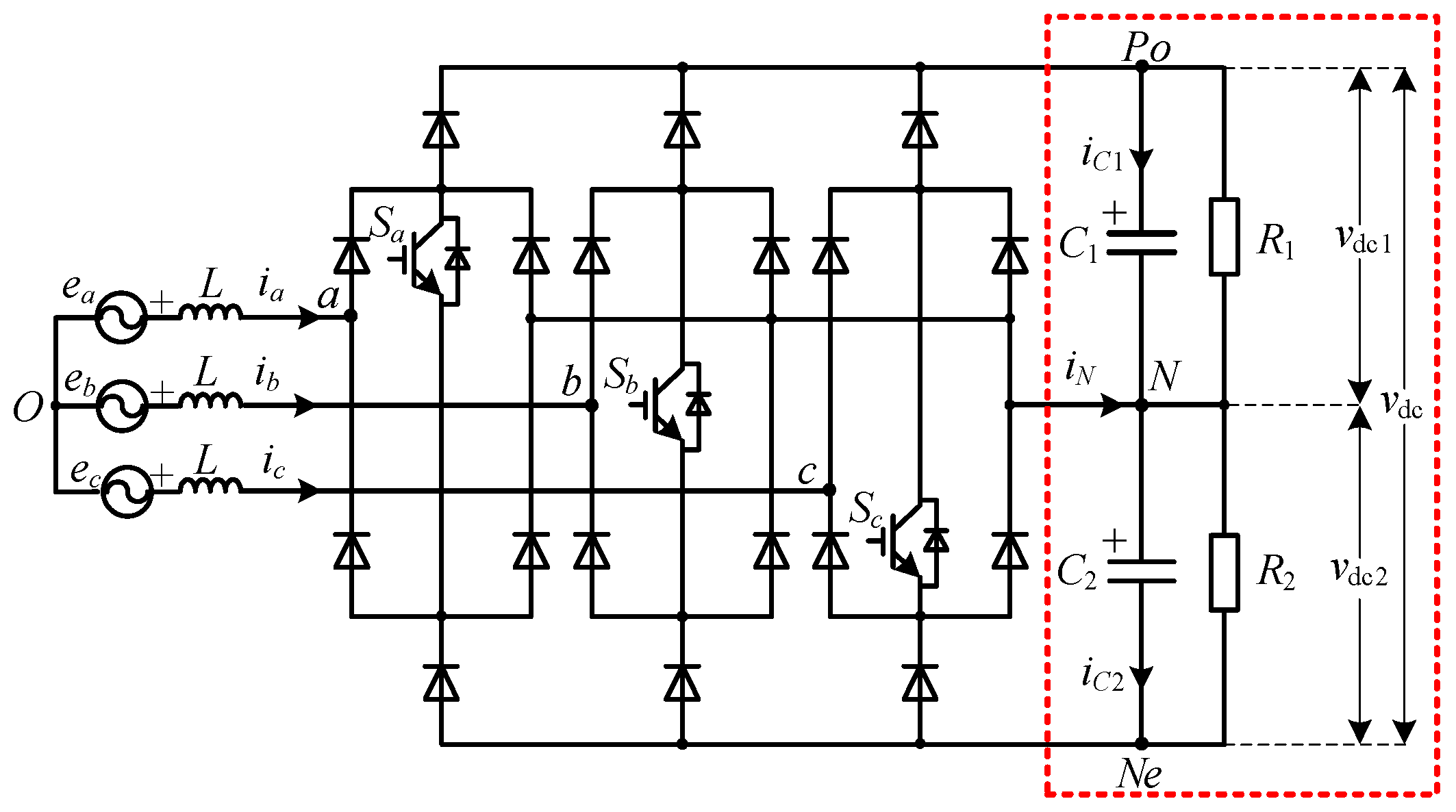
2. Analysis of Unbalanced NPV

2.1. Causes of Unbalanced NPV

The topology of the VIENNA circuit is shown in Figure 1.
The dashed box in the right half of Figure 1 shows the DC portion of the VIENNA circuit, in which the NPV problem will be analyzed. Taking the neutral point N on the DC side as the voltage reference point, the current flowing into the point N is defined as iN; the currents flowing through C1 and C2 are iC1 and iC2 respectively; the capacitance values of the capacitors C1 and C2 are equal, i.e., C1 = C2 = C; the DC bus voltage is defined as vdc, and the capacitor voltages are defined as vdc1 and vdc2 respectively. It can be seen from the theory of charging process of the current to the capacitor that:
{ v dc 1 = 1 C 0 t i C 1 d t + v dc 1 _ 0 v dc 2 = 1 C 0 t i C 2 d t + v dc 2 _ 0
where vdc1_0 and vdc2_0 are the zero-time voltages of C1 and C2 respectively.
Based on Kirchhoffs Current Law (KCL), it can be derived that:
i N = i C 2 i C 1
According to Equations (1) and (2), the NPV deviation ∆vdc can be obtained as:
Δ v dc = v dc 1 v dc 2 = 1 C 0 T s ( i C 1 i C 2 ) d t = 1 C 0 T s i N d t
According to Equation (3), it is clear that the root cause of unbalanced NPV is the non-zero integral value of iN during a control cycle Ts, which in turn leads to unequal charging and discharging voltages of capacitors C1 and C2. Therefore, in case of NPV deviation, the NPV can be balanced again by adjusting the flow direction or size of iN to act on the NPV.
As shown in Figure 1, the three-phase AC current in (n = a, b, c) and the three-phase voltage en are defined, with the output direction of the three-phase voltage en as the positive direction of in. The three-phase switching function sn is also defined, sn satisfying:
{ s n = 1 ; the   n th - phase   arm   switch   s n   is   turned   on . s n = 0 ; the   n th - phase   arm   switch   s n   is   turned   off .
As can be seen in Figure 1, only when a certain phase or multi-phase switch of the three-phase switches Sn is turned on, i.e., the corresponding switch function sn = 1, there is current flowing through the branch corresponding to the neutral point current iN and iN will not be zero. If all the three-phase switches are turned off, i.e., the corresponding three-phase switch functions all satisfy sn = 0, there is no current flowing through the branch corresponding to the neutral point current iN and the value of iN will also be zero. Therefore, the value of the neutral point current iN on the DC side of the VIENNA circuit depends on the three-phase switch sn and the three-phase current in, i.e., it satisfies:
i N = s a i a + s b i b + s c i c
Therefore, it can be seen from Equation (5) that when the NPV is unbalanced, different voltage vectors, i.e., different combinations of three-phase switch states, can be selected to adjust the NPV to balance again.

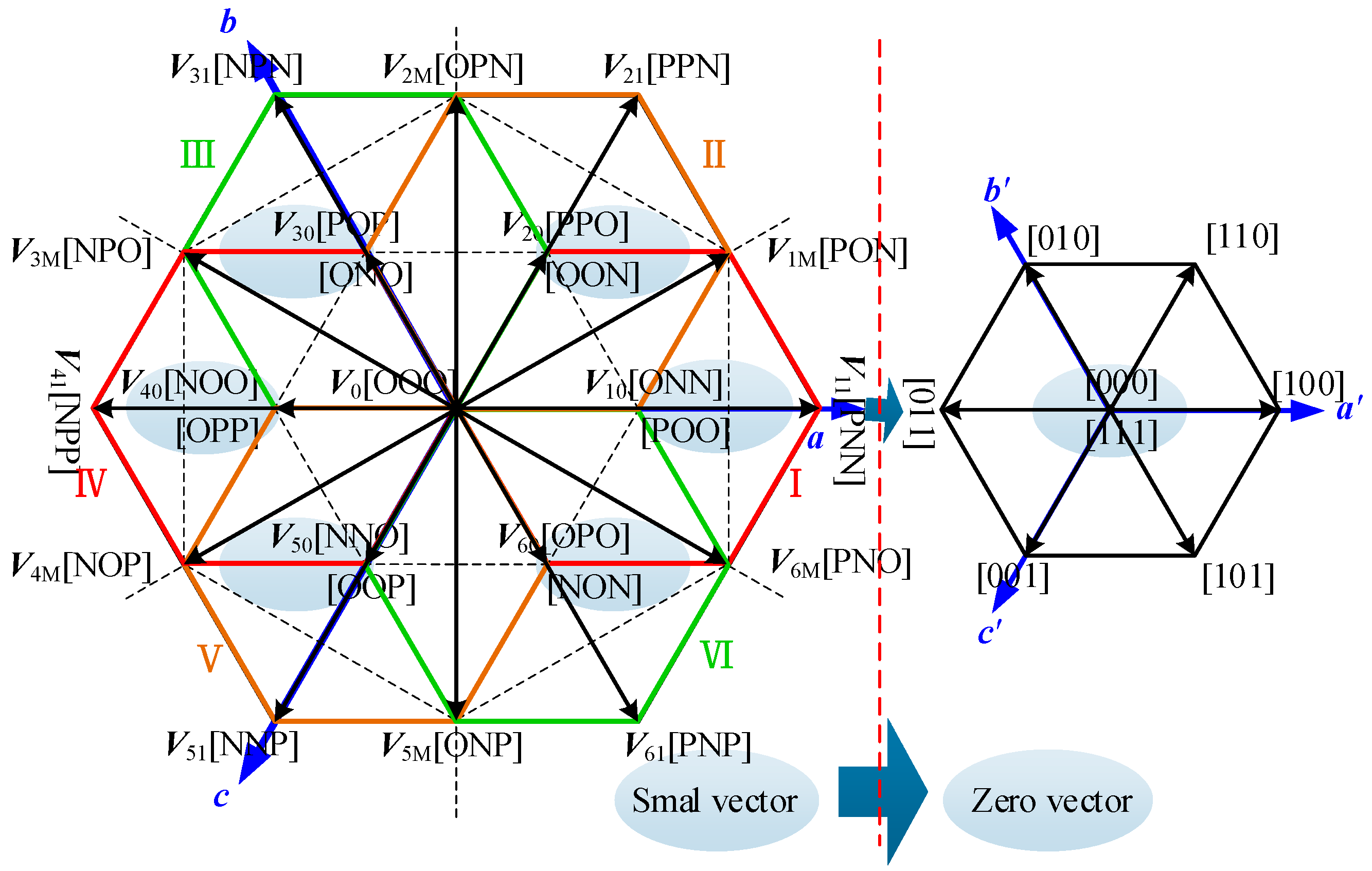
2.2. Effect of Different Voltage Vectors on NPV

As can be seen in Figure 1, the current flows in different paths with the turn on/off of a phase switch Sn, specifically path n-Po, n-N, or n-Pe. For the convenience of analysis, another function SWn is defined here for the switch Sn, as shown in the following equation.
S W n = { O S n   is   turned   on , s n = 1 ,   the   current   flows   to   n N   path P S n   is   turned   off , s n = 0 , i n > 0 , the   current   flows   to   n P o   path N S n   is   turned   off , s n = 0 , i n < 0 , the   current   flows   to   n N e   path
According to different switch states of the three-phase switch Sn and the flow path of the current, a total of 25 voltage vectors can be derived for the VIENNA circuit and can be divided into four main categories: zero-voltage vector, large-voltage vector, medium-voltage vector, and small-voltage vector. Among them, the small-voltage vector is composed of a positive small vector and negative small vector. Table 1 shows the neutral currents iN corresponding to different vectors.
The effect of different voltage vectors on the direction of iN is expressed by using the current flowing into or out of the neutral point N on the DC side, so that the direction of flowing into the neutral point N is positive and the direction of flowing out of the neutral point N is negative. As seen from Table 1, the neutral point current iN corresponding to the zero-voltage vector and large-voltage vector is 0, indicating that the zero-voltage vector and large-voltage vector have no effect on NPV and therefore NPV cannot be adjusted or controlled by the zero-voltage vector and large-voltage vector; the neutral point current iN corresponding to the medium-voltage vector is not zero, indicating that the medium-voltage vector will have an effect on NPV; however, because different medium-voltage vectors have different effects on NPV, and there is no obvious law to be followed, it is not suitable to use the medium-voltage vector to adjust or control NPV; similarly, the neutral point current iN corresponding to positive and negative small vectors is also not zero, so different small-voltage vectors will also have an effect on NPV. As can be seen in Table 1, the positive and negative vectors appear in pairs, with opposite effects on NPV; therefore, according to the characteristics of the positive and negative vectors, NPV can be adjusted or controlled by adjusting the selection method or operating time of the positive and negative vectors.

3. Strategy for NPV Balance Control Based on Selection Method of Dynamical Adjustment for Small-Voltage Vector

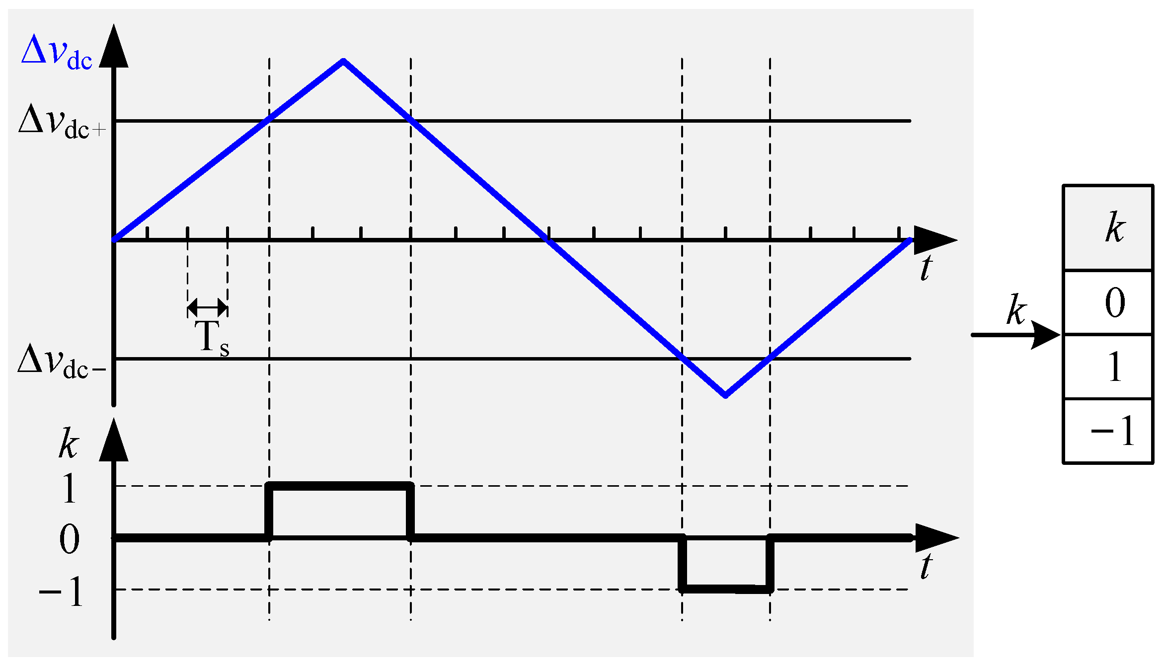
3.1. Basic Principles

As shown in Table 1, the positive vectors and negative vectors have opposite effects on NPV. Therefore, according to the direction and amplitude of NPV fluctuation, NPV can be controlled by dynamically adjusting the selection method of the small-voltage vector.
In the control of the three-level converter, a power frequency cycle is usually divided into six equal segments of 60-degree intervals each, while based on the correspondence between three-level vector and two-level vector, the three-level vector is corresponded to the two-level vector distribution in each 60-degree interval, and the three-level converter is equivalent to a three-phase two-level converter for control in the interval [23]. In this process, the paired small-voltage vector corresponds exactly to the zero-voltage vector of the three-phase two-level converter, as shown in Figure 2 below.
The two-level zero-voltage vector V0 includes V00[000] and V07[111]. If the control logic determines that the zero-voltage vectors are to be executed, the next step should also be selected between the two zero-voltage vectors. Generally, in order to reduce the switching frequency of each arm and the current THD, the selection of the two zero vectors is based on the principle of “minimum number of switching changes (MNSC)”. That is, according to the switching state of each phase in the previous control cycle, when making selection between the two zero vectors in the current cycle, only the switching state of one phase changes.
The principle of “MNSC” is implemented by the following equation:
s a = s b = s c = ( s a | | s b ) & & ( s b | | s c ) & & ( s c | | s a )
where is the logical operation “or”, & & is the logical operation “add”, and s n and s n are the switching states of each phase of the previous cycle and the current cycle, respectively, in the control process.
Based on the analysis, the process of NPV control using small-voltage vectors of the VIENNA circuit can be equivalent to the process of selective control for operating times of two zero vector in each 60-degree interval (corresponding to the two-level vector distribution). Therefore, an NPV control strategy based on the dynamical adjustment for selection method of the small-voltage vector is proposed. By judging whether the NPV is within the allowable range of fluctuation, it is decided whether the NPV needs to be controlled, and the appropriate vector is selected for control according to its fluctuation direction.
The allowable range of fluctuation [∆vdc−, ∆vdc+] and symbolic variable k of the NPV are defined, with k meeting:
{ k = 0 , When Δ v dc - < Δ v dc < Δ v dc + k = 1 , When Δ v dc > Δ v dc + k = 1 , When Δ v dc < Δ v dc -
where k is the variable that determines whether the NPV is outside the fluctuation range.
The acquisition method of symbolic variable k is shown in Figure 3.
As can be seen from Figure 3, after the NPV exceeds the minimum allowable fluctuation range, k is 0 or 1, respectively, and the maintenance time of k of 0 or 1 is related to the amplitude and time of the NPV exceeding the minimum fluctuation range. As long as the NPV exceeds the minimum fluctuation range, the value of k is maintained at 0 or 1 until the NPV is adjusted back to the minimum allowable fluctuation range based on the control strategy, and the maintenance time is an integral multiple of the control cycle Ts.
Further, two variables, k1 and k2, are defined in conjunction with k. The relationship between k and k1 and k2 is shown in Table 2.
As can be seen from the definitions in Table 2, k = 0 means that the NPV does not exceed the specified minimum fluctuation range, and in this case, k1 = 1 and k2 = 0 respectively, i.e., there is no need to add the NPV control function. Additionally, k = −1 or k = 1 means that the NPV exceeds the minimum allowable fluctuation range, and in this case, k1 = 0, i.e., it is necessary to add the NPV control function. When k1 = 0, k2 is defined as 0 and 1, respectively, and k2 is used to determine whether V00[000] or V07[111] is finally selected. If k2 = 1, the NPV is deviated and ∆vdc > ∆vdc+, V07[111] is selected; in contrast, if k2 = 0, the NPV is deviated and ∆vdc < ∆vdc-, V00[000] is selected.
Therefore, the NPV of the VIENNA circuit can be controlled by adjusting or controlling its own six pairs of small-voltage vectors, i.e., the two zero-voltage vectors corresponding to its two-level vector distribution. The NPV of the VIENNA circuit can be controlled in each 60-degree equal interval by the following equation:
s a = s b = s c = [ ( s a | | s b ) & & ( s b | | s c ) & & ( s c | | s a ) ] & & k 1 | | k 2
where, [ ( s a | | s b ) & & ( s b | | s c ) & & ( s c | | s a ) ] is Equation (7); k1 is the variable used to determine whether it is necessary to add the NPV control function; and k2 is the variable that determines whether V00[000] or V07[111] is finally selected when it is necessary to add the NPV control function.
Figure 4 shows the control flow of the VIENNA rectifier. The part in the dotted line box in Figure 4 is the realization process of the NPV control strategy proposed in this paper. It can be seen clearly in Figure 4 that the balance control of NPV is realized through real-time optimizing the selection method of positive and negative small-voltage vectors dynamically. With the principle of “MNSC” adopted together, the proposed NPV control strategy can control the NPV with the minimum switching times, and the implementation process is simple and convenient. Theoretically, it can effectively reduce the equivalent switching frequency, minimizing the influence on the AC current quality.

3.2. Applicability under Different Modulation Degree

Generally, the modulation degree M of the three-phase converter is the ratio of the modulating wave amplitude to the carrier wave amplitude. The value of M is also calculated to be equal to two times the ratio of the three-phase phase-voltage amplitude to the DC bus voltage value, as shown in the following equation.
M = V m _ amp V c _ amp = E n _ amp V dc / 2
where Vm_amp is the modulating wave amplitude, Vc_amp is the carrier wave amplitude, En_amp is the three-phase phase-voltage amplitude, and Vdc is the amplitude of the DC bus voltage vdc.
In general, the modulation degree is 0 < M < 1. Under special conditions, over-modulation (M > 1) will occur. If the modulation degree is too large or too small, the selection of switching method or voltage vector will be affected. In addition to the method for the control of the current and voltage of the whole circuit, the proposed NPV control strategy is an auxiliary control strategy and is specifically designed for the NPV control, and mainly implemented by adjusting the selection method of two zero vectors, V00[000] and V07[111], which is complementary to the whole control system of the circuit.
For different situations of modulation degrees, the proposed NPV control strategy is not to directly control the circuit according to the zero-voltage vector selected by the control algorithm of the whole circuit control system, but to adjust the selection of the two zero-voltage vectors according to the NPV deviation. For example, in case of low modulation degree, the probability of occurrence of the zero-voltage vector V00[000] is much greater than that of V07[111]; in the case of a high modulation degree, the probability of occurrence of the zero-voltage vector V07[111] is greater than that of V00[000]. However, according to the principle of the NPV control strategy, regardless of the selection of the two zero-voltage vectors by the control system of the whole circuit, the allocation and adjustment of V00[000] and V07[111] will be targeted according to the NPV deviation, instead of controlling the circuit directly according to the allocation of the two zero-voltage vectors derived from the comparison of the modulating wave and the carrier wave. Therefore, the NPV control strategy proposed is not affected by the magnitude of the modulation degree.

4. Simulation and Experimental Verification

With the VIENNA circuit verification platform, the proposed control strategy for NPV balance based on selection method of dynamic adjustment for small-voltage vector is compared with the traditional PI regulator-based ZSV-J through simulation and experimental verification, and the results are analyzed.
The parameters of the VIENNA circuit platform: verification power: 5 kW; three-phase voltage is obtained from the power frequency isolation transformer with a ratio of 2:1, so the root-mean-square (RMS) value of en: 110 Vac/50 Hz; DC voltage vdc setting: 400 Vdc; filter inductor L: 4 mH; DC voltage equalizing capacitors C1 and C2: 4700 μF.
During the verification, the unbalanced NPV is achieved by the unequal resistance of the two loads above and below the neutral point N on the DC side. If the two loads are equal: R1 = R2 = 16 Ω; if not equal, R1 = 20 Ω and R2 = 12 Ω.

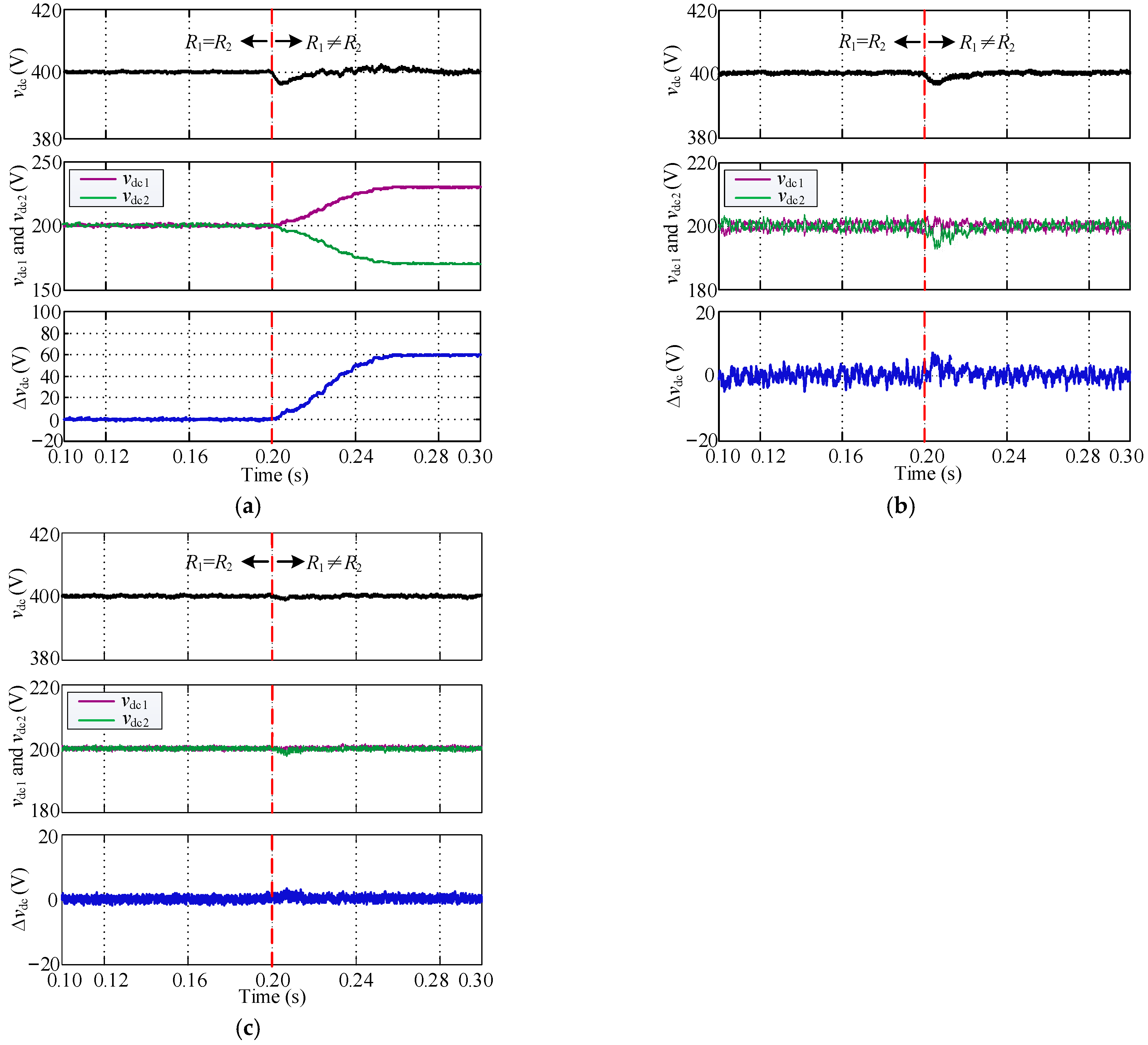
4.1. Simulation and Verification

Figure 5 shows the simulation waveform of the switching process of load resistances R1 and R2 from equal to unequal on the DC side of the VIENNA circuit. The switching of the two load resistances from equal to unequal is completed at the moment of 0.20 s. Figure 5a shows the simulation waveform when no NPV control strategy is adopted, while Figure 5b,c show the simulation waveforms using ZSV-J and the proposed NPV control strategy in this paper, respectively.
As shown in Figure 5a, when the two load resistances are equal, the values of vdc1 and vdc2 are equal, and when the two load resistances are switched to unequal, the NPV is deviated, the vdc fluctuation increases, and the harmonic content also increases. By comparing Figure 5b,c, when the loads are suddenly switched to be unequal, the NPV can be balanced again using both methods through the control process, and the proposed strategy has faster response and less NPV fluctuation than that of ZSV-J. Although the ZSV-J can slow down its PI regulator to make the level of NPV fluctuation reach or even less than that of the proposed strategy, it is at the expense of the response speed; similarly, the PI regulator of ZSV-J can be accelerated to make its adjustment speed reach or even exceed that of the proposed strategy, but it is at the expense of the control effect, and the NPV fluctuation will become higher. Thus, compared with ZSV-J, both in terms of the control effect and the adjustment speed, the proposed strategy is better.
Figure 6, Figure 7, Figure 8 and Figure 9 show the Fourier analysis of a-phase current ia in the simulation performed under different control strategies, respectively. Figure 6 shows the Fourier analysis of ia when NPV is balanced; Figure 7 shows the Fourier analysis of ia when NPV is unbalanced; Figure 8 shows the Fourier analysis of ia when NPV is controlled by ZSV-J; Figure 9 shows the Fourier analysis of ia when NPV is controlled by the proposed NPV control strategy.
As shown in Figure 6, The NPV is balanced when the two load resistances on the DC side of the VIENNA circuit are equal, and the THD of ia is about 2.06% and the DC harmonic content in the current is almost 0. As shown in Figure 7, when the two load resistances on the DC side become unequal and no NPV control strategy is adopted, the THD of ia can reach 3.36%, and the DC component content in ia is about 0.4%. As shown in Figure 8, the THD of ia is about 3.03% after NPV is balanced by ZSV-J, but the DC harmonic content reaches about 0.8%, which is because the principle of ZSV-J to control NPV is to use the output of the PI controller superimposed on the modulating wave of the control system, and such output is the constant flow when the harmonic components are not considered, and will be introduced into the current control loop, resulting in an increase of DC harmonics in the current (also verified in Figure 8). The simulation results in Figure 9 show that when NPV is controlled by the proposed NPV control strategy, the THD of ia is about 2.43% and the DC harmonic content is about 0.1%, which is lower than the value obtained by ZSV-J. From the above analysis, it can be seen that although NPV balance can be controlled effectively by the proposed strategy with lower DC component content and current THD compared with those when NPV is already balanced, the above values are still slightly higher. Therefore, the proposed strategy can control NPV balance, but also reduces the current quality to some extent, which is also theoretically inevitable.

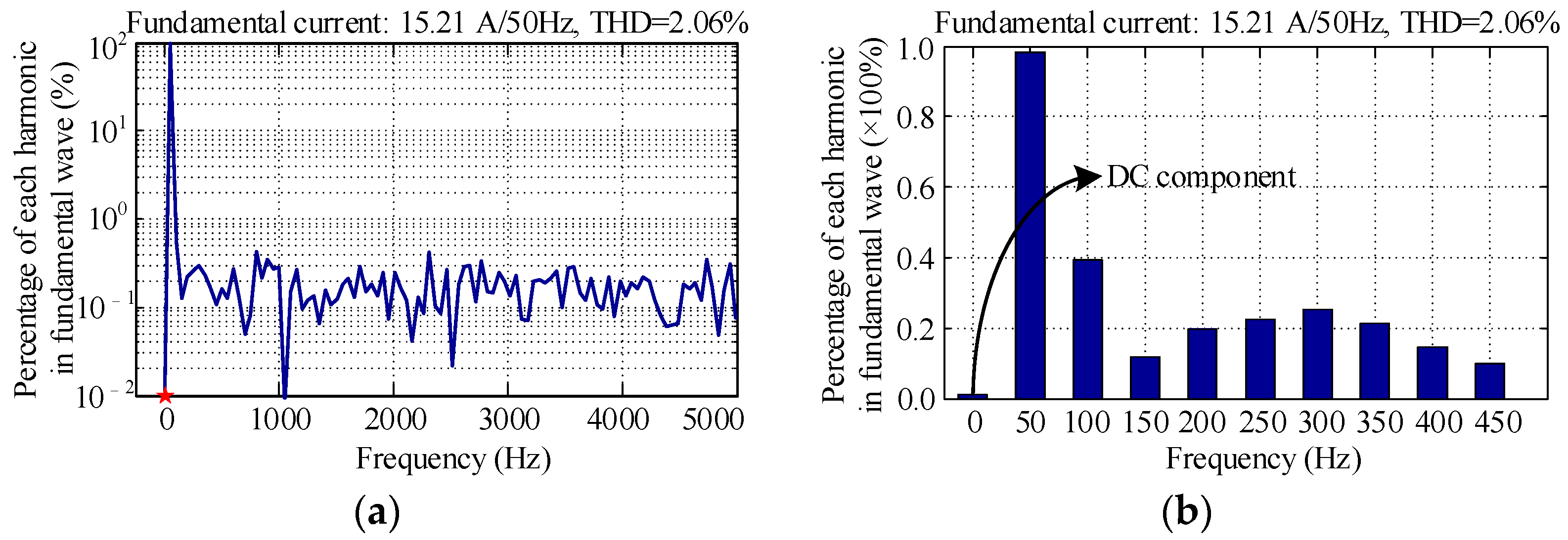
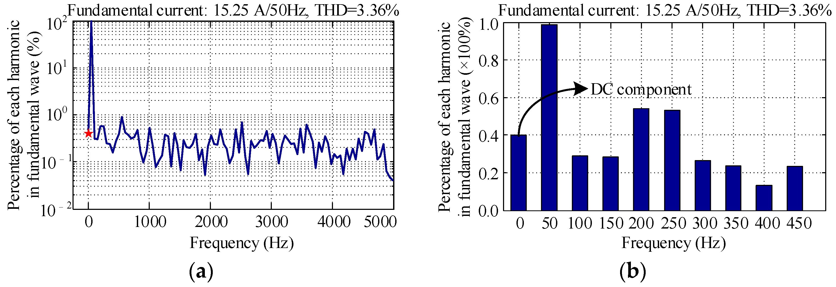
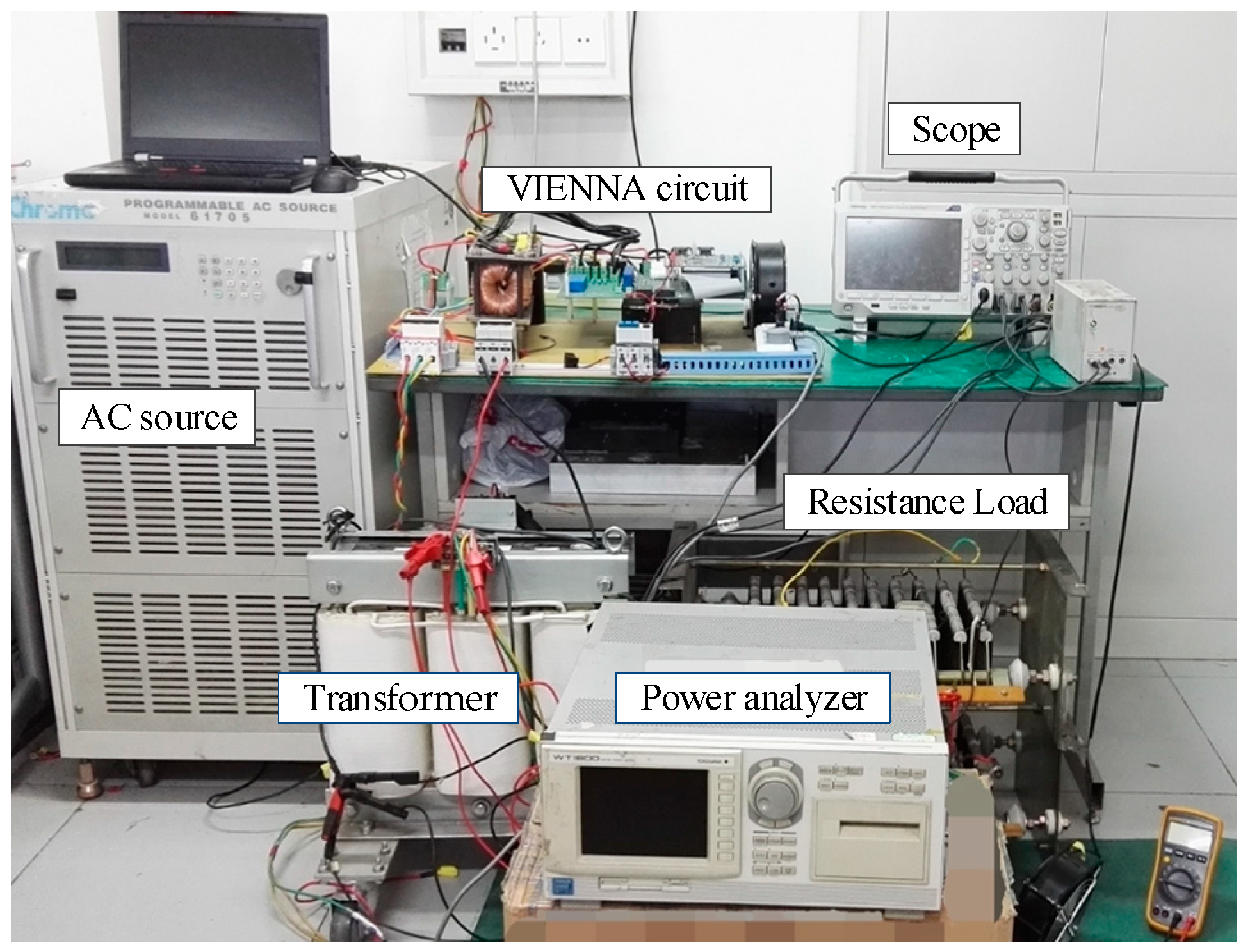
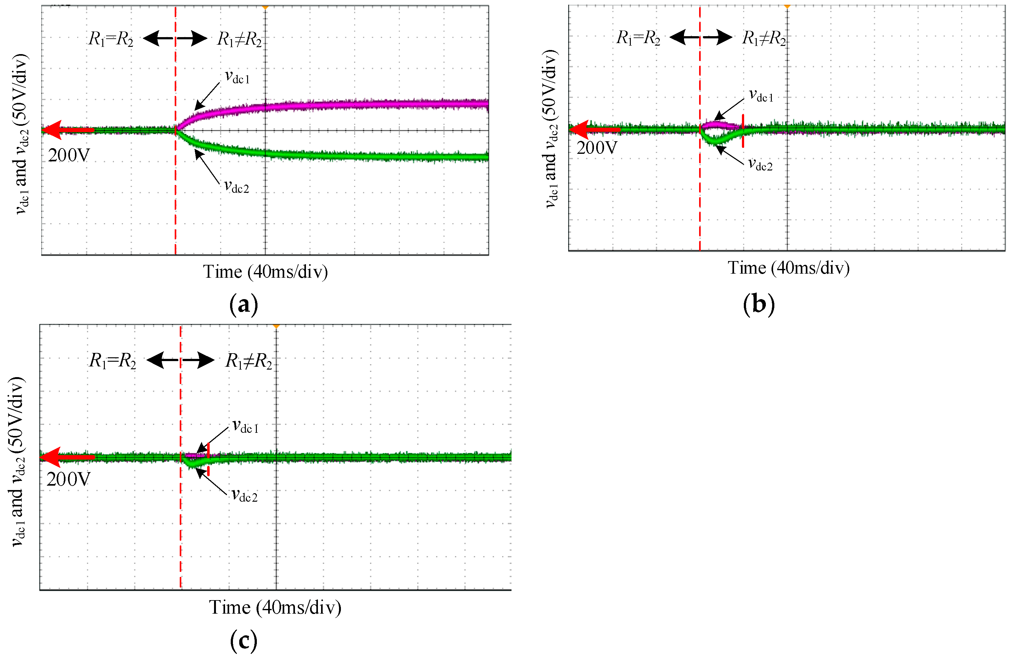
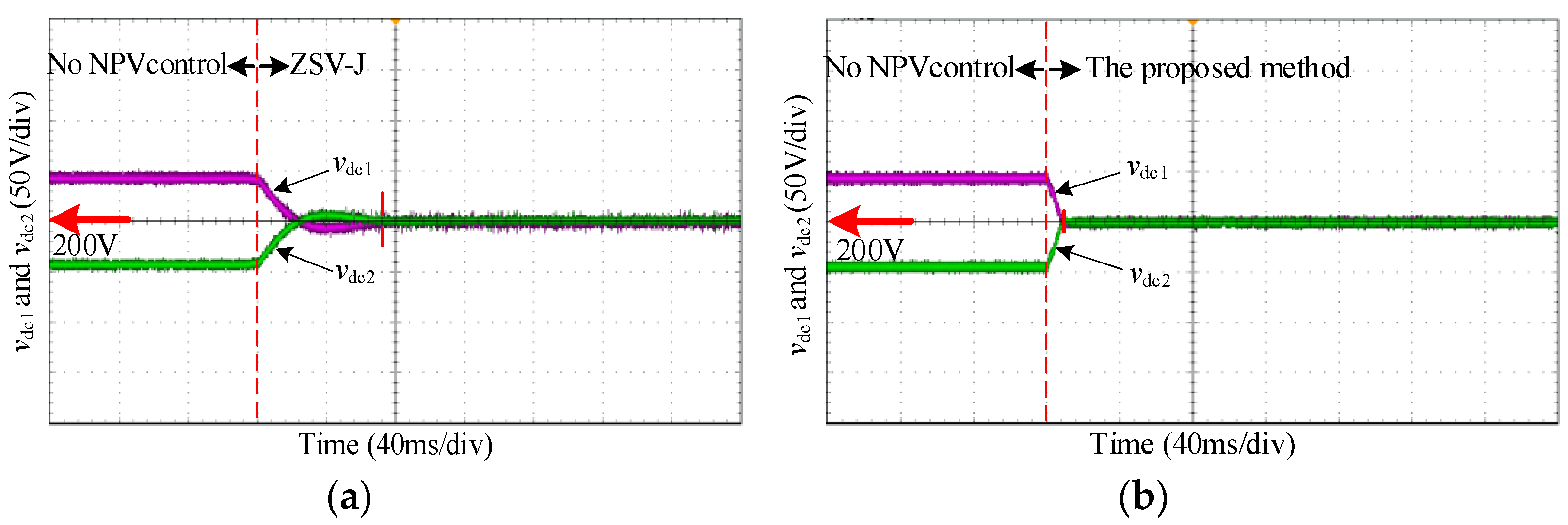
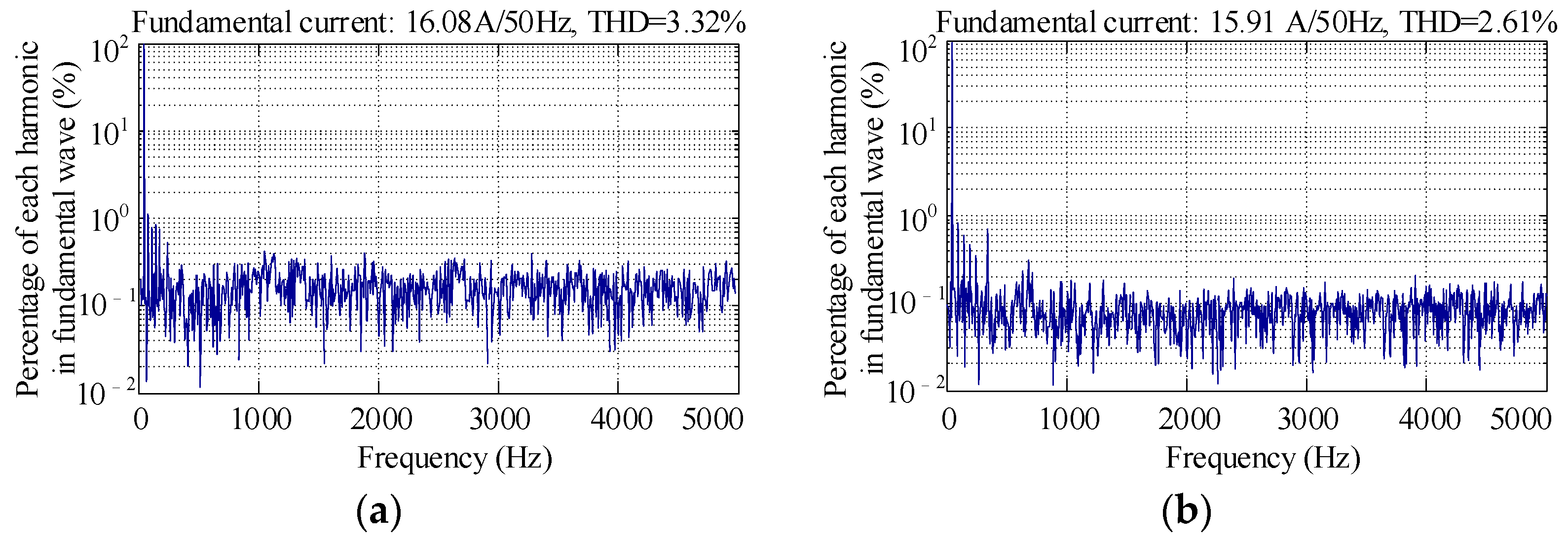
4.2. Experimental Verification

In order to verify the proposed NPV control strategy and compare it with ZSV-J, relevant experiments are performed here based on the VIENNA circuit hardware platform.
Figure 10 shows the prototype picture of the VIENNA circuit experiment platform. The parameter of the experiment platform is the same as the simulation situation.
As shown in the Figure 10, the experiment verification process of the proposed strategy is realized in the following way. An AC source sends the three-phase voltage to the AC terminal of the VIENNA rectifier through an isolation transformer with a transformation ratio of 2:1. The DC side (load side) of the VIENNA rectifier is two series resistors with adjustable resistance. The control circuit of the VIENNA rectifier is realized in digital mode, and the core control chip is a digital signal processor (DSP) named TMS320F28335. The control strategy proposed in this paper is realized through the core control chip.
As shown in Figure 11, under the premise of adopting two control strategies, respectively, the experimental results in the switching process of two load resistance values are from equal to unequal on the DC side of the VIENNA circuit. Figure 11a shows the waveforms when no strategy is used to control NPV, while Figure 11b,c show the waveforms when NPV is controlled by ZSV-J and the proposed strategy, respectively.
As seen in Figure 11a, when the two load resistances on the DC side are equal, even if NPV is not controlled, the two capacitor voltages vdc1 and vdc2 can remain equal. However, when the two load resistances on the DC side suddenly change to be unequal, NPV will deviate, while the fluctuation of the DC voltage vdc and the harmonic component content will also increase, which is the same as the simulation results. The comparison of Figure 11b,c shows that when the two load resistances on the DC side suddenly change to be unequal, the NPV can be controlled, balanced again through the control process, and the proposed NPV control strategy has faster response and less NPV fluctuation than that of ZSV-J. This conclusion is consistent with that verified by simulation.
Figure 12 shows the comparison of two NPV control strategies under the condition of two unequal load resistances on the DC side at the beginning of the experiment (i.e., the NPV is deviated at the beginning of the experiment), and the two NPV control strategies are adopted separately during the experiment. Figure 12a,b show the experimental waveforms of the two capacitor voltages after using ZSV-J and the proposed NPV control strategy, respectively.
Through the comparative analysis of Figure 12a,b, it can be concluded that the proposed NPV control strategy in this paper is better than ZSV-J in terms of response speed and control effect of NPV balance adjustment, which proves the feasibility and advantages of the proposed strategy.
Figure 13 shows the Fourier analysis results of current ia under the condition of the NPV has been adjusted by the two NPV control strategies. Figure 14 shows the input power P∑I and output power P∑O obtained by the power analyzer under the condition of the NPV has been adjusted by the two NPV control strategies. Table 3 sorts out the power data, THD data, and power factor data and calculates the conversion efficiency of the two NPV control strategies, respectively.
It can be seen from Table 3 that the working conversion efficiencies of ZSV-J and the proposed strategy are 94.02% and 95.08%, respectively. Therefore, compared with ZSV-J, the efficiency of the proposed strategy can obtain a 1.66% increase. In addition, the AC current THD of ZSV-J and the proposed strategy are 3.32% and 2.61%, respectively. Therefore, compared with ZSV-J, the AC current THD of the proposed strategy reduced by about 27.2%. Moreover, the power factor of the proposed strategy is also slightly higher than ZSV-J. The above comparison results prove the superiority of the proposed strategy over ZSV-J, which is also consistent with the simulation results. As both the two strategies are software methods and there are no additional hardware requirements, the costs of both the two strategies are low. In addition, in order to obtain a good NPV control performance, the ZSV-J needs to design or adjust the regulator parameters, and the proposed strategy needs logic operations to realize the real-time selection of the zero vectors dynamically. Therefore, in a comprehensive comparison, the implementation complexities of the two methods are similar, and they are both uncomplicated.
It should be pointed out that in the initial research process of this strategy, the principle of “MNSC” was not adopted to help select the zero vector, which led to the equivalent switching frequency increase in the situation of the NPV control strategy not being needed. After adding the principle of “MNSC”, just as the left part in Equation (9), that is, [ ( s a | | s b ) & & ( s b | | s c ) & & ( s c | | s a ) ] , the cover problem can be avoided, and the proposed strategy is optimized and more flexible and efficient.
However, up to the present research progress, the proposed strategy still has some limitations. Typically, it can only be applied to the similar three-level converter control occasion in this paper, that is, a power frequency cycle is divided into six equal segments of 60-degree intervals each, and the three-level converter is equivalent to a three-phase two-level converter for control in each 60-degree interval.
In the following further research, we will study how to control the NPV directly with the proposed strategy in the three-level situation, not only in the situation where the three-level converter is equivalent to a three-phase two-level converter for control in each 60-degree interval. This can further increase the applicability of the proposed strategy. At the same time, in order to test the performance of the proposed strategy more comprehensively, we will perform more work to compare it with more other strategies or research results. This can be more comprehensive in finding its advantages and disadvantages, so as to further optimize and improve it.

5. Conclusions

In this paper, taking the VIENNA circuit as an example, the NPV control strategy of the three-level converter is analyzed and studied. The factors causing NPV fluctuation and deviation are summarized, and the effect of different vectors on NPV in the control process is analyzed. On this basis, an NPV control strategy based on selection method of dynamical adjustment for small-voltage vector is proposed. By judging NPV fluctuation, different small-voltage vectors are selected dynamically to adjust NPV in real time. Finally, through simulation and experiment, the proposed NPV control strategy is compared with the traditional ZSV-J, and the feasibility and advantages of the strategy are verified. In short, the proposed strategy has the advantages of simplicity, fast dynamic response, good control effect, and low impact on AC current and is promising for the NPV control process of VIENNA circuits and other three-level circuits.

Author Contributions

Conceptualization and investigation, H.Z.; writing—original draft preparation and data curation, H.Z.; writing—review and editing, Y.Y.; supervision and review, Y.L.; guidance and advice, F.L. All authors have read and agreed to the published version of the manuscript.

Funding

This research received no external funding.

Institutional Review Board Statement

Not applicable.

Informed Consent Statement

Not applicable.

Data Availability Statement

The data used to support the findings of this study are available from the first author or the corresponding author upon request.

Conflicts of Interest

The authors declare no conflict of interest regarding the publication of this paper.

References

  1. Jain, A.; Khatri, N.; Shrivastav, P.; Mahor, A. THD analysis of cascaded H-bridge multilevel inverters in fuel cell applications. In Proceedings of the 2015 International Conference on Computer, Communication and Control (IC4), Indore, Indian, 10–12 September 2015; pp. 1–6. [Google Scholar]
  2. Li, J. Design and Control Optimisation of a Novel Bypass-embedded Multilevel Multicell Inverter for Hybrid Electric Vehicle Drives. In Proceedings of the 2020 IEEE 11th International Symposium on Power Electronics for Distributed Generation Systems (PEDG), Dubrovnik, Croatia, 28 September–1 October 2020; pp. 382–385. [Google Scholar]
  3. Li, J. Hybrid Propulsion Motor Drives Model based on Multi-level Inverters with Optimised Fuel Economy. In Proceedings of the 2020 IEEE Vehicle Power and Propulsion Conference (VPPC), Gijon, Spain, 8 November–16 December 2020; pp. 1–5. [Google Scholar] [CrossRef]
  4. Awal, M.A.; Bipu MR, H.; Montes, O.A.; Feng, H.; Husain, I.; Yu, W.; Lukic, S. Capacitor voltage balancing for neutral point clamped dual active bridge converters. IEEE Trans. Power Electron. 2020, 35, 11267–11276. [Google Scholar] [CrossRef]
  5. Peng, H.; Yuan, Z.; Zhao, X.; Narayanasamy, B.; Deshpande, A.; Emon, A.I.; Luo, F.; Chen, C. Improved space vector modulation for neutral-point balancing control in hybrid-switch-based T-type neutral-point-clamped inverters with loss and common-mode voltage reduction. Cpss Trans. Power Electron. Appl. 2019, 4, 328–338. [Google Scholar] [CrossRef]
  6. Cho, J.-H.; Ku, N.-J.; Han, J.-T.; Kim, R.; Hyun, D.-S. A simple control method for neutral-point voltage oscillation reduction of three-level Neutral-Point-Clamped inverter. In Proceedings of the IECON 2013—39th Annual Conference of the IEEE Industrial Electronics Society, Vienna, Austria, 10–13 November 2013; pp. 304–309. [Google Scholar] [CrossRef]
  7. Li, K.; Wei, M.; Xie, C.; Deng, F.; Guerrero, J.M.; Vasquez, J.C. A generalized discontinuous PWM based neutral point voltage balancing method for three-level NPC voltage source inverter with switching losses reduction. In Proceedings of the 2017 IEEE Applied Power Electronics Conference and Exposition (APEC), Tampa, FL, USA, 26–30 March 2017; pp. 1816–1820. [Google Scholar]
  8. Aly, M.; Mayoega, N.; Lior, A.M. A simplified SVPWM method for neutral point voltage control and common mode voltage reduction in three-level qZS T-type PV inverters. In Proceedings of the 2020 IEEE International Conference on Industrial Technology (ICIT), Buenos Aires, Argentina, 26–28 February 2020; pp. 1015–1020. [Google Scholar]
  9. Choi, U.M.; Lee, J.S.; Lee, K.B. New modulation strategy to balance the neutral-point voltage for three-level neutral-clamped inverter systems. IEEE Trans. Energy Convers. 2014, 29, 91–100. [Google Scholar] [CrossRef]
  10. Choi, U.M.; Jeong, H.G.; Lee, K.B.; Blaabjerg, F. Method for detecting an open-switch fault in a grid-connected NPC inverter system. IEEE Trans. Power Electron. 2012, 27, 2726–2739. [Google Scholar] [CrossRef]
  11. Wang, K.; Zheng, Z.; Xu, L.; Li, Y. Topology and control of a five-level hybrid-clamped converter for medium-voltage high-power conversions. IEEE Trans. Power Electron. 2018, 33, 4690–4702. [Google Scholar] [CrossRef]
  12. Tian, K.; Wu, B.; Narimani, M.; Xu, D.; Cheng, Z.; Zargari, N.R. A capacitor voltage-balancing method for nested neutral point clamped (NNPC) inverter. IEEE Trans. Power Electron. 2016, 31, 2575–2583. [Google Scholar] [CrossRef]
  13. Omri, B. Software method versus hardware method to balance capacitors voltages for three level NPC converter. In Proceedings of the 2017 International Conference on Green Energy Conversion Systems (GECS), Hammamet, Tunisia, 23–25 March 2017; pp. 1–4. [Google Scholar] [CrossRef]
  14. Zhang, H.; Zheng, W.; Yu, Y.; Li, H. A Hybrid discontinuous PWM neutral point balance method based on zero-sequence component for three-level NPC converter. In Proceedings of the 2019 22nd International Conference on Electrical Machines and Systems (ICEMS), Harbin, China, 11–14 August 2019; pp. 1–5. [Google Scholar] [CrossRef]
  15. Wu, X.; Tan, G.; Ye, Z.; Yao, G.; Liu, Z.; Liu, G. Virtual-space-vector PWM for a three-level neutral-point-clamped inverter with unbalanced DC-Links. IEEE Trans. Power Electron. 2018, 3, 2630–2642. [Google Scholar] [CrossRef]
  16. Xiang, C.; Shu, C.; Han, D.; Mao, B.; Wu, X.; Yu, T. Improved Virtual Space Vector Modulation for Three-Level Neutral-Point-Clamped Converter With Feedback of Neutral-Point Voltage. IEEE Trans. Power Electron. 2018, 33, 5452–5464. [Google Scholar] [CrossRef]
  17. Jiang, W.; Wang, P.; Ma, M.; Wang, J.; Li, J.; Li, L.; Chen, K. A Novel Virtual Space Vector Modulation With Reduced Common-Mode Voltage and Eliminated Neutral Point Voltage Oscillation for Neutral Point Clamped Three-Level Inverter. IEEE Trans. Ind. Electron. 2020, 67, 884–894. [Google Scholar] [CrossRef]
  18. Shen, J.; Schrüder, S.; Roesner, R. A neutral-point balancing controller for a three-level inverter with full power-factor range and low distortion. IEEE Trans. Ind. Appl. 2013, 49, 138–148. [Google Scholar] [CrossRef]
  19. Do, H.D.; Anuchin, A. An improved SVPWM strategy for three-level neutral point clamped converter capacitor voltage balancing. In Proceedings of the 2020 27th International Workshop on Electric Drives: MPEI Department of Electric Drives 90th Anniversary (IWED), Moscow, Russia, 27–30 January 2020; pp. 1–6. [Google Scholar]
  20. Chen, H.; Wu, P.; Lee, C.; Wang, C.; Yang, C.; Cheng, P. Zero-Sequence Voltage Injection for DC Capacitor Voltage Balancing Control of the Star-Connected Cascaded H-Bridge PWM Converter Under Unbalanced Grid. IEEE Trans. Ind. Appl. 2015, 51, 4584–4594. [Google Scholar] [CrossRef]
  21. Chen, F.; Qiao, W.; Wang, H.; Qu, L. A Simple Zero-Sequence Voltage Injection Method for Carrier-Based Pulse-Width Modulation of the Three-Level NPC Inverter. IEEE J. Emerg. Sel. Top. Power Electron. 2020. [Google Scholar] [CrossRef]
  22. Zhou, X.; Lu, S. A simple zero-sequence voltage injection method to balance the neutral-point potential for three-level NPC inverters. In Proceedings of the 2018 IEEE Applied Power Electronics Conference and Exposition (APEC), San Antonio, TX, USA, 4–8 March 2018; pp. 2471–2475. [Google Scholar] [CrossRef]
  23. Zhang, X.; Wu, X.; Geng, C.; Ping, X.; Chen, S.; Zhang, H. An improved simplified PWM for three-level neutral point clamped inverter based on two-level common-mode voltage reduction PWM. IEEE Trans. Power Electron. 2020, 35, 11143–11154. [Google Scholar] [CrossRef]
Figure 1. Topology of VIENNA circuit.
Applsci 11 05076 g001
Figure 2. Equivalent process from three-level small-voltage vector to two-level zero-voltage vector.
Applsci 11 05076 g002
Figure 3. Acquisition method of the symbolic variable k.
Applsci 11 05076 g003
Figure 4. Control flow of VIENNA rectifier.
Applsci 11 05076 g004
Figure 5. Performance comparison of the methods when the loads jump from equal to unequal. (a) No NPV control strategy is adopted; (b) ZSV-J; (c) the proposed NPV control method.
Applsci 11 05076 g005
Figure 6. Fourier analysis of ia when NPV is balanced. (a) Harmonic analysis; (b) low-frequency harmonics analysis.
Applsci 11 05076 g006
Figure 7. Fourier analysis of ia when NPV is unbalanced. (a) Harmonic analysis; (b) low-frequency harmonics analysis.
Applsci 11 05076 g007
Figure 8. Fourier analysis of ia when ZSV-J is adopted. (a) Harmonic analysis; (b) low-frequency harmonics analysis.
Applsci 11 05076 g008
Figure 9. Fourier analysis of ia when the proposed NPV control strategy is adopted. (a) Harmonic analysis; (b) low-frequency harmonics analysis.
Applsci 11 05076 g009
Figure 10. Prototype picture of VIENNA circuit experiment platform.
Applsci 11 05076 g010
Figure 11. Performance comparison of the two strategies when the loads jump from equal to unequal. (a) No NPV control strategy is adopted; (b) ZSV-J; (c) The proposed NPV control strategy.
Applsci 11 05076 g011
Figure 12. Performance comparisons of the two NPV control strategies when the two loads are unequal. (a) ZSV-J; (b) the proposed NPV control strategy.
Applsci 11 05076 g012
Figure 13. Fourier analysis and comparison of current ia of the two NPV control strategies in the experiment. (a) ZSV-J; (b) the proposed NPV control strategy.
Applsci 11 05076 g013
Figure 14. Input power and power comparison of the two NPV control strategies in the experiment. (a) ZSV-J; (b) the proposed NPV control strategy.
Applsci 11 05076 g014
Table 1. Corresponding iN of different vectors.
Zero Voltage VectoriNLarge Voltage VectoriNMedium Voltage VectoriNSmall Positive Voltage VectoriNSmall Negative Voltage VectoriN
OOO0PNN0OPNiaONNiaPOOia
PPNPONibPOPibONO−ib
NPNNPOicNNOicOOPic
NPPONPiaOPPiaNOOia
NNPNOPibNONibOPOib
PNPPNOicPPOicOONic
Table 2. Judgment rule of NPV control requirements.
CategoryNPV Control Requirementskk1k2
vdc < ∆vdc < –∆vdc+Not required010
vdc > ∆vdc+Required101
vdc < ∆vdcRequired−100
Table 3. Efficiency, THD, power factor, cost, and complexity comparison of the two NPV control strategies.
Control MethodsInput Power P∑I (W)Output Power P∑O (W)Efficiency ηTHDPower FactorCostComplexity
ZSV-J5339502094.02%3.32%0.9901LowNeed design or adjust regulator parameters
Proposed strategy5282502295.08%2.61%0.9919LowNeed logic operations
Publisher’s Note: MDPI stays neutral with regard to jurisdictional claims in published maps and institutional affiliations.

