Review

HVdc Circuit Breakers: Prospects and Challenges

1
Department of Electrical Engineering, University of Engineering and Technology, New Campus, Lahore 54000, Pakistan
2
Department of Electrical Engineering, University of Lahore, Lahore 54000, Pakistan
3
Department of Electrical Engineering, Xi’an Jiaotong University, Xi’an 710049, China
4
Department of Electrical and Computer Engineering, King Abdulaziz University, Jeddah 21589, Saudi Arabia
5
Departamento de Ingeniería de Sistemas y Automática, Universidad de Sevilla, 41004 Seville, Spain
*
Author to whom correspondence should be addressed.
Appl. Sci. 2021, 11(11), 5047; https://doi.org/10.3390/app11115047
Submission received: 26 February 2021 / Revised: 20 April 2021 / Accepted: 26 April 2021 / Published: 29 May 2021
(This article belongs to the Section Electrical, Electronics and Communications Engineering)

Abstract

:
The integration of offshore wind farms has revitalized the interest in multi–terminal high voltage direct current (M–HVdc) transmission grids. HVdc breakers’ importance has increased as M–HVdc grids are now a commercial truth. Several HVdc circuit breaker technologies have been developed, published, and appeared as prototypes for HVdc networks. This paper summarizes the HVdc breaker technologies from the last two decades, distributed mainly in literature. A comparison of various state–of–the–art HVdc breakers is presented. Further, areas are identified where further research and development are required. The goal is to provide primary challenges and prospects in the HVdc breaker field.

1. Introduction

The successful and reliable maneuver of multi–terminal high voltage direct current (M–HVdc) systems will impose the evolution of efficient dc grid protection and flexible control infrastructures. This will compel the power electronics and power systems operators to evolve appropriate protection schemes with HVdc breakers and control approaches to enhance the dc grid operation efficiency and reliability [1,2,3]. Since 1950, almost 200 point–to–point HVdc transmission grids have already been installed worldwide [4]. During the last two decades, few two–terminal HVdc applications have been evolved to acquire functional multi–terminal HVdc (M–HVdc) grids [5,6]. The M–HVdc systems consisting of multiple voltage source converters (VSCs) stations have become a promising solution because of recent development and the increased accessibility to high power VSCs from multiple vendors [6].
Considerable advantages and application ideas have been recognized and proposed regarding the M–HVdc system/grid [7,8,9]. The M–HVdc systems can serve as the most promising solution for integrating harvested offshore wind energy into ac mainland grids [10]. Several ideas for the European dc super grid have been scrutinized, like the European Wind Energy Association (EWEA) [11]. DESERTEC EUMENA’s will develop cooperation between three continents; Europe, the Middle East, and North Africa. In [12,13,14], M–HVdc connections are proposed for DESERTEC and EWEA visions. The M–HVdc grid can also find its applications for the interconnection of multiple non–synchronous ac areas [15,16,17]. However, the main obstacle in realizing M–HVdc networks on a large scale is their high vulnerability to dc faults. The rising fault current rate is high because of the small inductance, which demands fast interruption technology [18]. Thus, the recognition of the M–HVdc grid as a reliable and efficient network is forcefully subjected to the disposal of HVdc circuit breakers (DCCBs), making them one of the keys empowering technology [19,20,21,22,23].
There is a substantial difference between the needs and necessities of dc and ac breakers. Mainly because of the unavailability of natural zero crossings in dc systems. The DCCBs would interrupt dc fault currents swiftly and dissipate vast amounts of energy stored in the dc grid’s inductances. Today, only transfer and load switches are in use for the HVdc applications. However, DCCBs are available for low and medium–range dc applications. HVdc CBs are not commonly available, or proposed DCCBs have minimal current breaking capability. Numerous DCCB designs have been proposed based on parallel and series connections of classical ac interrupters, charging units, semiconductors, resonance circuits, and varistors—each concept associated with certain drawbacks and advantages. Most of the ideas investigated only a single or few aspect of many design requirements, but no literature has given an overall picture.
The objective of this paper is to provide a comprehensive overview of HVdc circuit breaker technologies, including recent significant attempts in the development of modern HVdc circuit breakers, and, by this, to revive the discussion on this very topic. HVdc breakers from technology giants like ABB, Siemens, GE, etc. are assessed and a detailed performance–based comparison is provided, not available in the literature. Functional analysis of each technology is presented. Additionally, different technologies based on derived information from literature are compared. Finally, recommendations for the improvement of circuit breakers are presented.

2. High Voltage Direct Current Networks

The first commercial installation of HVdc transmission technology is seen in 1954 [24]. HVdc technology is not only feasible and attractive from a technical point of view but also is economical. Typically, HVdc systems are employed for two reasons: (i) To transfer bulk power over large distances via long transmission lines; (ii) to connect unsynchronized ac networks and networks operating at different frequencies (back–back). The dc transmission has low losses than ac for long transmission lines. Mainly, HVdc converter technology can be divided into two: Classical technology—Thyristors–based line commutated converters (LCC) and recent technology—insulated gate bipolar transistors (IGBTs)–based (self–commutated converters) voltage source converters (VSCs) [25,26,27,28,29].
Power flow in LCC–HVdc is regulated by adjusting the firing and extinction time of gate signals before commutation to the next valve, as the thyristor is only a turn–on device. The flow of power is unidirectional; thereby, LCC is sometimes called a current source converter (CSC) [30]. Thus, the change in power flow direction would be problematic, as it requires a polarity change. Reactive power (Q) is consumed at both inverter and rectifier sides, which has to supply via filters and extra capacitors from the ac side. The LCC–HVdc substation produces less than 1% losses at rated current, of which 50% comes from the converter station transformer [31]. However, LCC technology is continuously advancing (e.g., capacitor commutated conversion consumes relatively less reactive power [32,33]), and the filter size is also compromised by employing tuned active dc and ac filters [25,32,33,34]. The recently installed LCC–HVdc transmission links are provided in Table 1. LCC has the highest power and voltage rating in HVdc converter topologies, blocking voltage of 10 kV with a current rating up to 6250 A [35,36,37].
Constant dc–link voltage is obtained from self–commutated voltage source converters, where large capacitors are used. Real power (P) is transmitted softly in both directions and can provide reactive power at both receiving (inverters) and sending ends, which reduces the filter size considerably. Filter size is also reduced as only high–frequency harmonics are present because of pulse width modulation (PWM) due to the availability of high power IGBTs. However, a VSC station contributes to losses by 1.6% [31,38,39], of which 70% comes from converter valves. Five terminal VSC–HVdc Zhoushan link is installed in 2014 with ± 200 kV [38]. Each station’s transmission capacity is 100, 400, 100, 300, and 100 MW, respectively. Details of some prominent VSC–HVdc transmission links are given in Table 2.
In the event of dc fault, anti–parallel diodes to IGBTs start acting as an uncontrolled rectifier. A high rate of dc fault current is experienced due to the small dc inductance of the system. Furthermore, dc capacitors discharge and aid the fault current [40,41]. VSCs are no longer well–regulated, and thus the fault current is only restricted by the ac breakers [28]. Here, the DCCBs should be doing the same, but HVdc CBs are not available.
Table 3 summarizes the dissimilarities between LCC–HVdc and VSC–HVdc transmission technologies. Significant differences concerning the DCCB are; loss of VSC control in dc fault and different sizes of the inductances and capacitances (result in a different rate of rising dc fault current).
VSC technology is rapidly advancing. New topologies are proposed to reduce converter losses (<1%), harmonics contents, and capability to extinguish the dc fault current [40,41,42,43,44,45]. R. Marquardt proposed a multi–modular converter (MMC) topology, an advanced form of VSC–HVdc circuits [46,47]. This topology is based on the cascaded connections of several sub–modules of two IGBTs and a parallel capacitor. Sub–modules arrangements may use full–bridge (FB) or half–bridge (HB) cascaded connections. FB–MMC can override the overcurrent fault condition of HB–MMC. Thus, dc fault reverse blocking is realized by blocking the flow of current through the switches during the dc fault [45,48,49] at the expense of high switching losses, which develops the need for fast–acting DCCB.
Most of today’s HVdc interconnections are two terminals. A factual M–HVdc system consists of several onshore and offshore VSC’s positioned in different topographical locations. Thus, control, operation, and energy management are more complex and challenging. In the event of dc fault, to ensure the reliable and smooth operation of M–HVdc systems, it must be possible to isolate the faulty portion/system from a healthy system. The ac breakers can interrupt full/complete short circuit current, while HVdc circuit breakers have only limited ratings. The DCCBs are expensive and larger than ac CBs of the same rating. Thus, new methods are developed to extinguish the fault from today’s point–point dc–link based on; control [50] or by installing the ac CBs on the ac side to de–energize the system [51]. Such a protection scheme operation may take a few 100 ms [52,53,54] to a few seconds [53], but only suited to two terminals HVdc systems. De–energization of complete HVdc system is also suggested in [40,55,56,57] but limited to three to four terminals [58].
For reliable operation of the M–HVdc grid, the availability of dc circuit breakers would be vital. The first parallel M– HVdc system was anticipated, and a debate started in 1963 [59,60,61], whereas the series M–HVdc grid was discussed in 1965 [62]. However, major interest in M–HVdc emerges in 1980s [22,56,58], and [63,64,65].
More recent studies suggest VSC–based multi–terminal HVdc systems for integration of offshore wind farms [64,65,66,67]. Numerous challenges need to be dealt with before M–HVdc grid becomes a reality, which are: Communication between converter stations [64,65,66,67,68], control [69,70], and primary and back–up protection schemes [40,41,42,43,44,45,46,47,48,49,50,51,52,53,71,72,73].
It is challenging to decide unambiguously whether the HVdc link should be based on LCC or VSC as both technologies offer specific benefits and demerits. Table 4 gives the pros and cons of the M–HVdc grid based on LCC and VSC, respectively. LCC–HVdc is mature and well established and shows fewer losses. However, in the event of a fault on the ac side, commutation failure is experienced, leading to dc–link’s ultimate devastation. Conversely, VSC–HVdc technology is vulnerable to dc faults, as explained earlier.
HVdc technology is principally vital for DCCBs as it defines the needs for HVdc CB, which could be different for both technologies. For instance, in VSC–based technology, CB needs to be fast and must have a capacity to interrupt high fault currents. The needs of the breaker for both technologies are discussed in the subsequent section.

3. HVdc Circuit Breakers

A neutral bus switch (NBS), ground return transfer breaker (GRTB), neutral bus ground switch (NBGS), high–speed bypass switch (HSBS) for parallel line switching, metal return transfer breaker (MRTB), and isolation switches [74,75] are the dc interrupters commonly used for various switching techniques in the present point–point topology of HVDC transmission networks. The dc interrupters have only been available in limited rating and number, which is merely approaching 1.6 times the nominal rating to interrupt the short circuit current. The maximum available rating is 500 kV, 4 kA, or 250 kV, 8 kA. In addition, dc breakers are comparatively expensive and bulky than ac breakers of the same rating. So, initially ac breakers and isolators were employed on ac side of converters as substitute of dc breakers in point–point HVdc configuration [76]. In a medium or low voltage dc applications, various techniques based on solid–state switches or switching arcs have been developed to interrupt the short circuit current [73].
The major problem encountered in the development of DCCBs is the absence of the usual zero–crossing phenomenon in the dc system [77,78,79]. The basic requirements which must be accomplished by the breakers are;
  • Develop a zero–crossing current to interrupt the fault current
  • Must dissipate the stored energy of the inductance
  • Able to hold the voltage profile of the system after the interruption of fault current
The first two conditions form the dc circuit breaker basis, and the third particular attribute distinguishes them from ac breakers. Secondary requirements of the dc breaker in addition to the features mentioned above are as follows [80];
  • The dc breaker must interrupt the fault current, as mentioned earlier, in the VSC–based M–HVdc system.
  • The maximum voltage produced across the breaker must be within safe limits to coordinate with the system’s insulation. This is of prime importance when the system operates at a nominal voltage to switch heavy load currents.
Excessive developments and researches are being conducted on HVdc breakers from six decades [57,58,59], but interest in DCCBs is dropped significantly after 1985 due to no success in developing a fast and short interruption mechanism. However, new studies on DCCB appeared [80,81,82,83] recently boomed the interest in HVdc grids. Developments are made in technologies, which ultimately improve the DCCB design and configuration [84,85]. This paper focuses on the more recent dc breaker field developments, special attention to the latest VSC/MMC–based M–HVdc grids.

Distinctiveness of HVdc Breakers

DC limiting reactor is a major component of an HVdc circuit breaker. It is an inherently bulky element of the breaker that is expected to handle maximum dc fault current without getting itself damaged. When the limiting reactor is connected in an M–HVdc grid, the line impedance, as well as the grid stability is considerably affected. Moreover, an increase in transient voltage is observed at the breaker terminals. Apart from this, the fault current may face an initial rate of rising for both external as well as internal faults. The series impedance between the fault location and the converter is lower in an external fault as compared to an internal fault. Initially, for the first few milliseconds, an internal fault might give a higher fault current than an external fault. As for the protection of dc transmission lines, the external fault is considered outside of the protection zone defined by the dc reactor’s boundary. That is why, the impact of external fault is mitigated due to the inductor’s boundary effect and a smaller fault current is noticed under external fault as compared to an internal fault [86,87]. However, after several milliseconds of fault inception, due to lower series impedance, there will be a higher rise in the current level in case of an external fault than an internal fault. The HVdc breakers are designed to interrupt the fault current in the first few milliseconds only. An aggregated model of dc breaker is shown in Figure 1.

4. HVdc Circuit Breaker Topologies

Three kinds of HVdc breakers are reviewed in this paper: Solid–state, electro–mechanical, and hybrid HVdc circuit breakers.

4.1. Electro–Mechanical HVdc Breakers

Electro–mechanical dc breakers are divided into active and passive resonance DCCBs as this type of breaker works on resonance phenomena.

4.1.1. Electro–Mechanical Passive Resonance HVdc Breakers

The passive DCCB is an obsolete technology that was developed for the LCC–HVDC system [88]. These breakers have a slow response time and are bulky, massive, larger in size, thus interest is dropped to use this breaker for dc grid protection. But these breakers have comparatively low power losses than all other dc breakers. A passive resonance DCCB is shown in Figure 2.
The nominal current path is shown in Figure 2. Rated current (Is) flows through this path when the switch (CB) is closed under normal operation. Normally, interrupting circuits are developed with the air blast circuit breaker. Condition of zero–crossings is established with a series resonant circuit connected to an inductor and a capacitor, this forming a commutation path. This condition is necessary for breaker interruption [89]. Energy is absorbed by the surge arrestor during the fault. The current oscillation between the nominal and the commutation path is enabled by the interruption. This interruption works at the natural frequency. When the amplitude of the oscillating current is greater than the input current, zero–crossings occur. At this stage, the switch stops the flow of current in the nominal path [18,74].
As a result, the capacitor will be charged by the flow of current (Io). Consider the capacitor voltage exceeds a dc breaker’s voltage capability. Surge arrestor will respond, an ideal zero point will be created on the decrease of current. This will help in the interruption of current. The maximum voltage value is 500 kV for passive electro–mechanical HVdc breakers, being employed for many years. This breaker clears the 5 kA fault current within a fault clearing time of 60–100 ms [90]. However, the development of semiconductor technology has reduced the attraction of electromechanical breakers for short circuit faults in multi–terminal HVdc systems [91].
The interruption process can be clearly understood by the analysis of the current equation. The differential equation during fault interruption is [89]:
L c d 2 i s d i 2 + R c + u a r c i s d i s d t + 1 C s i s = I o C c
i s = I o   1 + e 1 2 L   R c + u a r c d i s · S i n ω c t  
where ω c = 1 L c · C c   and if R c + u a r c d i s < 0 ; then “is is oscillating with growing amplitude. In this scenario, the first zero–crossing of current would be enough for the breaker to interrupt the dc fault.

4.1.2. Electro–Mechanical Active Resonance HVdc Breakers

In this mode, a current oscillation supported by the pre–charged commutation capacitor Cc would increase instantly. It will rise to oppose the main CB’s current when the current is commutated to the LC branch. This topology is also presented as a hybrid interruption technique. Typically, a thyristor is employed as a disconnector and commutator in this type of breaker. This notion is also termed a two–stage interruption method. As this concept has various variants, the two main topologies are introduced in [92,93]. The first variant of electro–mechanical active resonance CB is depicted in Figure 3 [94,95].
Under a steady–state condition in this first variant, the breaker switches S2, S3, and S4 are open while the only main breaker switch S1 is closed. The capacitor Cc is pre–charged with a negative initial voltage Vc0. When fault current is encountered, S1 is opened, while S2 and S3 would close simultaneously. Then the fault current is opposed by the reverse current rising through the LC branch, and a zero–crossing will occur, and thus the current is commutated to parallel branches. Whence the Cc is charged, S2 opens, and the current through it will reduce to zero. Subsequently, the switch S4 will close, and discharging of Cc will happen in the loop Cc–S4–S3–Lc– Cc. When a current–zero happened in S3, it turns off, and the main breaker current again commutates into the loop Rlim–Lc–Cc–S4. However, S4 opens upon current–zero creation, resulting in a new power equilibrium in which the capacitor is completely charged.
In the second variant of active resonance dc breakers, current interruption is realized by closing the switch S3 only, as shown in Figure 4. When a fault is detected in the second variant, S3 is closed, and S1 is opened simultaneously to generate a current–zero in the main breaker. Eventually, S3 will open when the capacitor is completely charged [94].

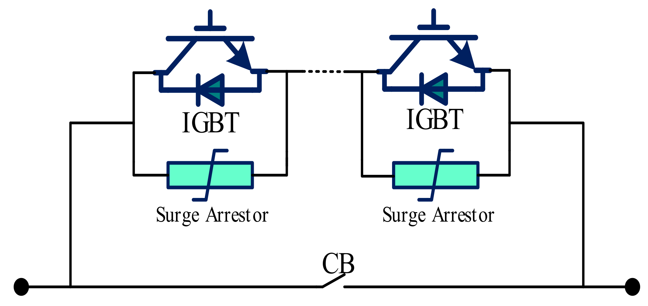
4.2. Solid State HVdc Breakers

The solid–state circuit breakers (SSCBs) are lighter, simpler to repair and maintain, and have a faster operating time than electro–mechanical dc breakers. SSCB is a dynamic era of research and the latest contribution is presented in [96,97]. Two topologies of SSCB are implemented and summarized in [96]. In the first topology, CB is connected in parallel with a surge arrestor, as shown in Figure 5. In contrast, in the second topology, a free–wheeling diode is connected, as shown in Figure 6.

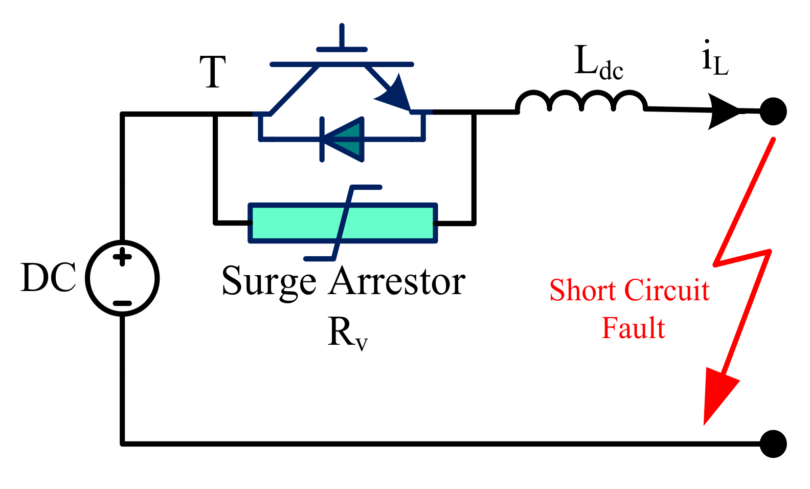
4.2.1. Solid State HVdc Breakers Employing Surge Arrestors (SA)

Under the steady–state condition, the current flows from the dc source to the load through IGBTs (T) in SS–based HVdc breakers employing SA, as shown in Figure 5 [95,97]. However, the semiconductor switch turns–off when a fault is detected. This results in a rapid rise in voltage until the surge arrester starts to conduct. The surge arrester is designed so that any voltage greater than the grid voltage is choked/blocked, leading to the de–energization of the line inductance [97]. Then the load current is commutated to the surge arrester. The IGBT voltage is quite limited to the surge arrester’s clamping voltage and is assumed to be Vdc + Vmargin. The impedance at the fault point is also supposed to be small when IGBT turns–off at time t = 0.
Vmargin is applied across Ldc and the inductor current is calculated as [89]:
i L = I o V Margin L dc t
where I o is the amplitude of the fault current at t = 0. The time to turn off the fault current T open is derived as follows:
T open = L dc V margin I o
The energy absorbed by the surge arrestor can be given by:
W R = V dc V margin + 1 1 2 L dc I o 2
WR is giving total energy being absorbed and suppressed by the surge arrester at the time of fault clearance, I 0 2 shows the short circuit current, and LC signifies the system’s inductance. In a high voltage system, larger values of Vdc than Vmargin are used to suppress the voltage across IGBT and reduce the conduction losses. In such a scenario, the term in the bracket of (5) becomes large which means WR is enough higher than the stored energy in Ldc at t = 0, 1 2 L dc I 0 2 . Thus, surge arrester’s high capacity is required to accommodate IGBT’s more suppressed energy. The more is voltage suppressed across the IGBT, the higher the capacity surge arrestor required [97].

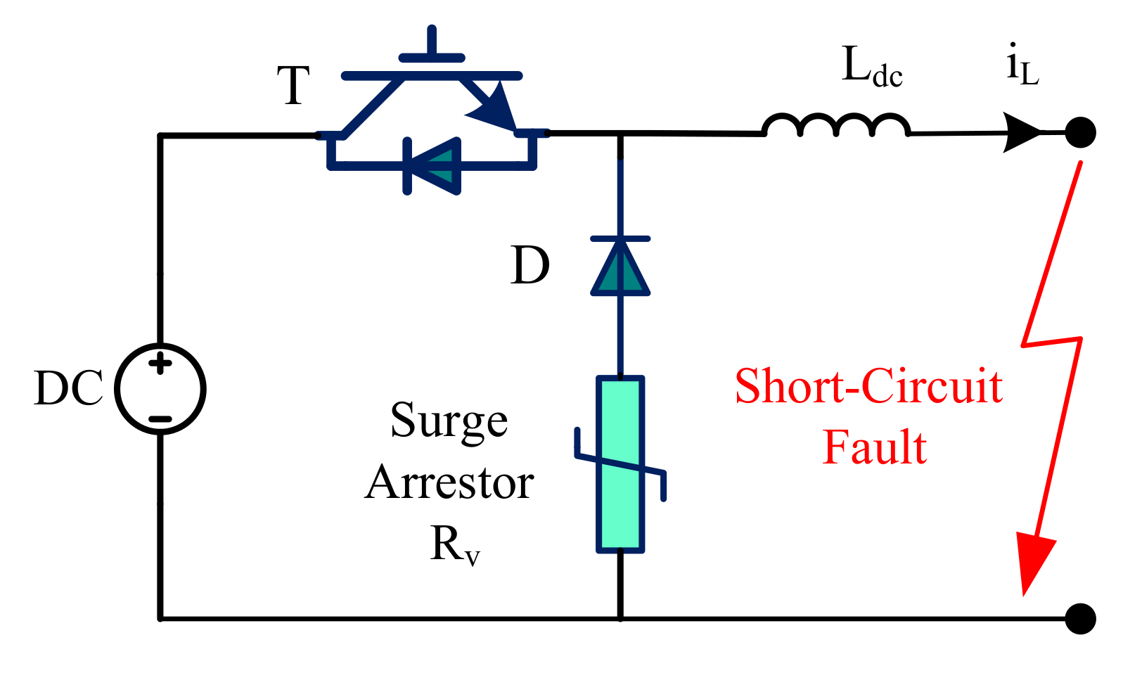
4.2.2. Solid State HVdc Breakers Employing Free–Wheeling Diode

The second variant of SSCB employs a free–wheeling diode in parallel with the IGBT to bypass any reverse voltage impulse and protect the IGBT against the voltage spikes, as shown in Figure 6. A surge arrester is also used to absorb the dissipated heat during the fault. This quick action of dissipation and absorption of generated heat improves CB’s reliability.
During normal operating conditions, IGBT (T) is on, and load current iL passes through it. However, on fault detection at t = 0, the fault current is commutated to D as T turns–off. So, the inductance Ldc is gradually demagnetized by the Rv, thus the fault current starts reducing. If Vv expresses the clamping voltage of Rv, the surge voltage across T will be Vdc + Vv. As no power flow through T after turning off, thus energy absorbed in this breaker during turn–off operation is equal to 1 2 L dc I 0 2 . Thus, the energy WR is:
W R = 1 2 L dc I o 2
Small values of WR in (6) than (5) suggest the small rating and volume of surge arrestor in the second topology with the reduced suppressed voltage across IGBT [94,95].
Several benefits are evolved for solid–state breakers compared to other circuit breaker technologies. The absence of mechanical structures improves the SSCB’s response time, resulting in lower turn–off time. Additionally, the higher voltage across the inductor allows the demagnetization process to be performed faster [98]. The fast turn–off method of SSCB reduces the peak current to a limited level compared to other breaker technologies. Thus, the solid–state breaker has a lower power loss for the same grid voltage. Therefore, it may be assumed that an SSCB is an optimal choice due to lower turn–off time, reduced component cost, and lower peak current irrespective of cable length and grid voltage.
However, this is not the case because of one substantial shortcoming; the high on–state losses. It can be concluded from comparison graphs (grid voltage vs. time and grid voltage vs. maximum current) provided in [98,99] that for low to medium grid voltages, low turn–off time and low peak voltage are not quite enough to counter the power losses during the on–state. However, in high voltage grids, solid–state topology shows an advantage since the power saved per circuit breaker is sufficient to make them more economical than the other circuit breakers, even when the on–state losses are considered.

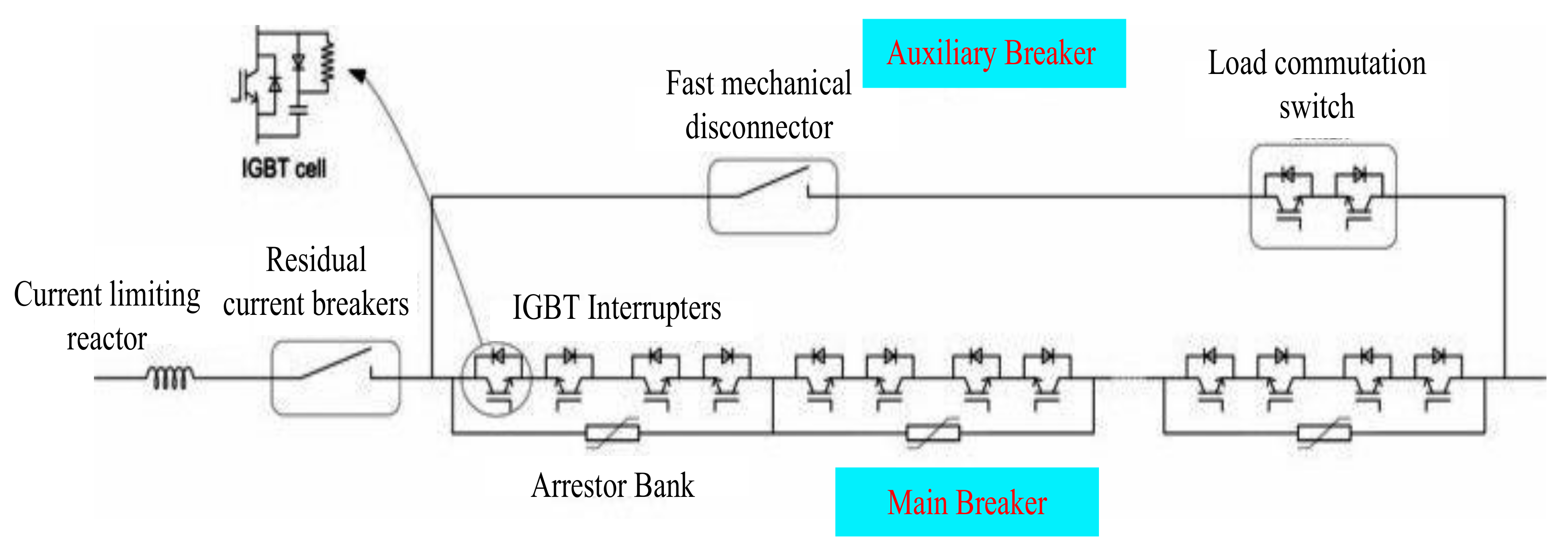
4.3. Hybrid HVdc Circuit Breakers

This type of circuit CB opens new prospects for fast switching and extinguishing the arc. They employ solid–state devices and mechanical switches for switching operations, as suggested by its name, hybrid dc breakers. The hybrid circuit breaker theory is suggested to overcome the shortcomings of solid–state and electro–mechanical breakers. The use of electronic components that are sensitive to short–circuit faults makes the hybrid DCCB expensive. The steady–state reliability of hybrid DCCB is fairly high, but the failure rate is much greater than that of a similar voltage rating of ac breaker. The structure of a hybrid dc breaker is very complicated as it contains electronic devices and mechanical components that lead to a high failure rate, and the electronic components are also comparatively fragile [100]. However, the breaker’s failure to timely isolates the fault can be harmful to both human beings and the protected component. Hybrid DCCB continues to attract a lot of attention, as recently witnessed in [101]. Moreover, Alstom [102] and ABB [80] have established hybrid dc circuit breaker prototypes with significant enhancement in recent research [103,104,105]. There are many available topologies of hybrid DCCB at various development stages, but only two attract more attention. Figure 7 shows the basic idea of hybrid DCCB [94,95]. The operation of hybrid CB is similar to that of SSCB but with the only difference that the hybrid breaker has additional sets of solid–state switches connected in parallel. Compared to other breakers, hybrid CB has low losses, and because of the solid–state switches, it is faster and reliable.

5. Comparison

A comparison of different dc breaker technologies in terms of power loss, current rating, voltage rating, and interruption time is presented in Table 5.

5.1. Interruption Time

Electro–mechanical dc breakers have a grumpy switching response up to 100 ms while the fault current interruption time of solid–state DCCB is less than 1 ms. However, hybrid dc breaker’s operating time is, between the two topologies, 2–30 ms, an attractive attribute for high power systems applications [106,107,108,109,110,111,112,113].

5.2. Power Losses

Electro–mechanical and hybrid dc breakers with no semiconductor switch in the main current path show low power loss than all the topologies. The reason for this is the low voltage drop across the metal contacts of the main breaker. Even a hybrid dc breaker configuration having a low rating semiconductor switch in the main current path shows reasonable power loss, no more than 0.1% of VSC station power loss. On the contrary, solid–state dc breakers suffer from high power losses as the number of IGBT or other semiconductor switches is installed in the main current path, which is why relatively high voltage drop across the CB. Power loss for SSCB reaches up to 30% compared to the VSC station.

5.3. Voltage Rating

Electro–mechanical dc breakers of 550 kV voltage ratings are available, while hybrid DCCBs are tested experimentally for 120 kV. However, SS dc breakers are not available for high voltage applications, only been designed and executed for medium voltage levels. But SSCB of 800 kV voltage rating can be realizable by looking at the development in semiconductor devices [106,107,108,109,110,111,112,113].

5.4. Current Rating

Electro–mechanical breakers can interrupt up to 8 and 4 kA currents with active resonance and passive resonance circuits, respectively. On the other hand, the current interruption of 9 kA is experimentally proved for hybrid DCCB, while interruption of 16 kA is discussed in simulations [114]. Considering HVdc SSCBs, the current interruption rating of 5 kA is achievable.

6. More Recent Activities and HVdc Breaker Related Technologies

6.1. Combined Optimization of HVdc Breaker’s Topology and Control

Most studies on M–HVdc system topologies and HVdc breakers only focus on a specific distinct aspect. Sometimes, it is assumed that the dc breaker is known, and the network controller is designed, while the system control activities are set; other times, as per the requirements of the DCCB, and the breaker is designed. No comprehensive combined efforts are reported in the literature to optimize the entire system. It is advised to regulate the control structure to ease the needs of the dc breakers. The rise of the dc short circuit current can be reduced by adding additional inductance to the VSC station’s dc side, but it would slow down the system’s normal operation. On the other hand, the dc short circuit current can also be limited by employing high grounding impedance for a line–to–ground fault. Focusing on just one aspect is most probable, not the best solution as only a collective optimization can only achieve the globally optimal solution. Multi–modular converters are an example of combined optimization [115,116,117]. The voltage level inside the valve is a fragment of the total dc–link voltage, and, in principle, it can be interrupted at these levels. Thus, the corresponding dc breaker has a lesser rated voltage, but the valve scheme needs to be remodeled to include a dc circuit breaker. Thus, the satisfying results may be achieved by the dc breaker and valve design’s joint efforts.

6.2. Standardization

In the future, more than one manufacturer’s components are expected to be used to design and build a multi–terminal HVdc grid. M–HVdc grid norms and standards are discussed in [118,119]. This is particularly important for the dc breakers and their interaction with the protection systems and networks [120].

6.3. Fault Current Limiters

Most of the concepts used to accomplish the basic requirements of dc breakers, as discussed earlier, are applicable to fault current limiters (FCL) in both dc and ac systems. FCLs are deployed to limit the fault current in power systems, as the name infers. Thus, FCL would increase the impedance of the system either self–triggered or externally triggered. Further, FCL has to handle a large amount of dissipated energy during the limitation. Additionally, some FCL can interrupt the fault currents. However, sometimes, a load break switch in series of FCL is placed to interrupt the fault current if alone FCL cannot do so. Interested readers are recommended to see the literature on FCL in [121,122], as no detailed discussion on FCL is repeated in this article.
Solid–state current limiters (SSFLs) [123,124], and hybrid FCL using fast mechanical switches [125] are two important topologies but both circuits have not been realized for high voltages so far. However, medium voltage FCLs (fuses) are self–triggered with interruption ability but are one–shot devices, need to replace manually, and widely available up to 10–20 kV [126,127]. Superconducting FCLs of resistive type use an intrinsic physical property of superconductors to lose its zero resistance above a critical current density. Such FCLs have low conduction losses, resettable and fast, but extensive cooling is required to acquire a superconducting state.
Mostly, FCLs are designed and deployed on distribution levels (36 kV). However, only resonance links and limiting reactors with capacitors are being used for high voltage applications; transmission and sub–transmission lines [122]. Researchers are working to develop high voltage FCLS [128,129]. Any progress in this field would also benefit the HVdc breaker activities.

6.4. Testing, Only HVdc Breakers Are Tested So Far

The dc breaker, along with its auxiliary components, should be tested for functionality during development. Direct testing is not applicable for high power ratings; thus, synthetic testing techniques to be employed [130,131]. Contrary to ac breaker testing, the dc breaker strongly interacts with the dc–grid and requires actual energy levels to apply stress to the breaker properly. This is quite challenging, expensive, and leads to excessive heating (e.g., the energy dissipating elements). Specific test models have been designed and employed to test the components [132]. The individual component test can be performed and interpreted through power–hardware–in–the–loop methods. In this technique, only the component under consideration is the actual physical device, while all other parts are interfaced with the test object through a real–time simulator [133,134,135,136]. It could mean that the interaction of the DCCB with the network and the energy dissipation is simulated. The associated current through the dc breaker is calculated and driven by a flexible current source.

7. Available HVdc Breakers from Tech Giants

7.1. ABB’s Hybrid HVdc Breaker

ABB proposed a hybrid dc breaker comprised of the main branch and an extra branch as shown in Figure 8 [136,137]. The control strategy for fault current interruption of this hybrid HVdc breaker is given in Figure 9 [138]. A shunt path is designed by an ultra–fast mechanical disconnector in series with a semiconductor–based load commutation switch. This semiconductor–based dc breaker is divided into various units with independent arrester banks designed for rated current and voltage breaking capability. In contrast, the energy capability and lower voltage are matched by the load commutation switch. Residual current is interrupted by an isolating breaker after fault clearance, and the arrester bank of hybrid CB is protected from thermal overload by isolating the faulty line from the dc–grid [139].
During steady–state and normal operation, the current in the main breaker is zero, and the only path for the current is through the shunt. In case of dc fault, the load commutation switch instantaneously commutates the current to the main breaker, and the ultra–fast mechanical disconnector opens. The main breaker interrupts the current with a mechanical disconnector in an open condition.

7.2. Alstom’s Hybrid HVdc Breaker

A hybrid dc breaker from Alstom Grid is a combination of a semiconductor breaker and a mechanical HVdc switch. Figure 10 depicts the structure of this circuit breaker [102]. Besides mechanical contact, the core branch also includes a low voltage switch. Alstom dc breaker has two extra branches: (i) energy absorption and (ii) commutation branch (or arming branch). The control strategy for fault current interruption of this kind of hybrid breaker is shown in Figure 11.
During steady–state and normal operation, the current will pass through the main branch. The low voltage switch produces low power losses and the contact voltage is also zero. Several components are connected in parallel for current rating and series for voltage rating. In the event of a fault, a huge amount of fault current will flow through the main branch. As soon as the fault is detected, the commutation branch will be closed, and the low voltage switch will be opened. Most of the fault current will commutate through the commutation branch at this moment. The mechanical switch may open without any arcing across its terminals until the fault current flow through the main branch is mitigated to nearly zero. When the commutation branch is turned off, the fault current is forced to pass in the energy absorption unit. The voltage developed across the energy absorption unit must be larger than the source voltage to decrease the fault current and reduce the breakdown voltage of the mechanical switch. The total time to current extinction and the rate of fault current is determined by the difference of voltage developed across the energy absorption unit and the source in an inductive circuit [102].

7.3. General Electric’s Superfast Medium Voltage HVdc Breaker/Switch

Existing dc circuit breakers developed for point–point applications are generally costly, too big, and too slow for use in a medium–voltage dc (MVdc) distribution grid. The energy department of Advanced Research Projects Agency–Energy (ARPA–E), United States recently awarded a research grant of $5.8 M to a team of engineers at General Electric (GE) to develop a superfast MVdc breaker [140,141]. The GE research team proposes to use gas plasma to construct a superfast switch. Timothy Sommerer, the chief investigator on the ARPA–E grant, says a typical HVdc breaker requires an air–conditioned building, measures 10 × 10 × 25 feet, and costs between $5 M to $10 M. A dc breaker made of power semiconductor switches commutates the current in a few milliseconds, which gives time to operate a main mechanical breaker. Such a topology would be very much expensive to set up an MVdc grid.
The GE research team is designing a breaker that uses plasma or charged gas to operate between the two electrodes. A small current flowing through a mesh wire employed within the two electrodes is used to operate the switch. Their goal is to build a dc breaker of rating 100 kV in the next three years, which is reflected as a boundary between high and medium dc voltage.
Plasma switches have the benefit of a smaller size. Semiconductor switches can also operate rapidly, but the cooling requirement demands more space to apart the switches to stay cool. Hence, the equipment size increases. As plasma switches can work at very high temperatures, they can operate close together and adjusted in confined space of smaller footprints.
A comparison is provided in Table 6 of anticipating commercial HVdc breakers from Tech giants.

8. Summary and Future Research Needs

In the previous sections of this article, several technical areas were identified and discussed related to the HVdc breakers. Summary of the conversed literature and future research directions are discussed in the following [72]:
i.
Improvements in the existing dc breaker topology can be fetched by optimizing the size of components such as; inductors, capacitors, varistors, etc. The goal is to reduce interruption time, size, and cost.
ii.
The switching arc’s oscillation growth and interruption capability can be optimized by studying the arc characteristics in detail under various vacuum and gas breaker conditions. Verification and derivation of the constraints are in mathematical arc models.
iii.
Comsol Multiphysics® simulations of dc arcs are recommended for high oscillatory current and during the interruption.
iv.
Medium–voltage dc breakers can be employed for high–voltage levels by enhancing the technology, series connections, or by smearing dc breakers across the medium–voltage levels in multilevel converter topologies.
v.
The use of hybrid dc breakers is recommended. As it can have features of both mechanical and solid–state breakers with reduced ratings of switches. Thus, size, cost, and interruption time are reduced.
vi.
Fast mechanical disconnectors with low on–state losses and high recovery of withstand voltage have sufficient arcing voltage for swift commutation. Such switches can be deployed in hybrid dc breakers for fast actions.
vii.
The use of new wide–bandgap power semiconductor devices (e.g., SiC or GaN) is recommended to have negligible on–state losses.
viii.
Active gate driving technologies that may improve the performance of semiconductor switches in a pure solid–state circuit breaker are recommended.
ix.
Integrated optimization of the whole M–HVdc system should be done to comply with the necessities of breaker–control protection.
x.
The standards and norms for the operation of multi–terminal HVdc systems must be defined to develop the proper dc–grid protection.
xi.
New testing methods for the dc breaker or its components should be designed. As dc breakers have strong network interaction, power–hardware–in–the–loop techniques would be advantageous.
xii.
GE Plasma switches that may operate at high temperature, more economical, and are adjusted in confined space of smaller footprints are recommended for medium dc voltage.

9. Conclusions

In this paper, prospects and challenges to HVdc breaker development are presented along with a review of the main concepts of HVdc breaker and different contenders. This topic has been evolved rapidly over the last two decades. The research and advancements in HVdc breaker technology certainly increase with the emergence of real–life multi–terminal HVdc grids. The best HVdc breaker candidate would have low cost, after achieving the required performance level.

Author Contributions

Conceptualization, A.R. and A.M.; methodology, A.R.; formal analysis, A.R., A.M., K.R., R.M. and S.G.; investigation, U.A. and G.A.; figure, K.R. and S.G.; resources, U.A.; data curation, A.R., A.M., R.M. and G.A.; writing—original draft preparation, A.R., A.M. and R.M.; writing—review and editing, U.A., G.A, K.R. and S.G.; funding acquisition, U.A. All authors have read and agreed to the published version of the manuscript.

Funding

This research received no external funding.

Institutional Review Board Statement

Not applicable.

Informed Consent Statement

Not applicable.

Data Availability Statement

Not applicable.

Acknowledgments

The authors are thankful to the Department of Electrical Engineering, The University of Lahore–Pakistan, and King Abdulaziz University, Jeddah Saudi Arabia for providing facilities to conduct this research.

Conflicts of Interest

The authors declare no conflict of interest.

References

  1. Chaudhuri, N.R.; Chaudhuri, B. Adaptive droop control for effective power–sharing in multi–terminal DC (MTDC) Grids. IEEE Trans. Power Syst. 2013, 28, 21–29. [Google Scholar] [CrossRef] [Green Version]
  2. Abdel–Khalik, A.S.; Massoud, A.M.; Elserougi, A.A.; Ahmed, S. Optimum power transmission–based droop control design for multi–terminal HVDC of offshore wind farms. IEEE Trans. Power Syst. 2013, 28, 3401–3409. [Google Scholar] [CrossRef]
  3. Raza, A.; Dianguo, X.; Yuchao, L.; Xunwen, S.; Williams, B.W.; Cecati, C. Coordinated Operation and Control of VSC Based Multiterminal High Voltage DC Transmission Systems. IEEE Trans. Sustain. Energy 2016, 7, 364–373. [Google Scholar] [CrossRef] [Green Version]
  4. Rouzbehi, K.; Miranian, A.; Candela, J.; Luna, A.; Rodriguez, P. A generalized voltage droop strategy for control of multi–terminal dc grids. IEEE Trans. Ind. Appl. 2015, 51, 607–618. [Google Scholar] [CrossRef]
  5. Adam, G.P.; Williams, B.W. Multi–pole voltage source converter HVDC transmission systems. IET Gener. Transm. Distrib. 2016, 10, 496–507. [Google Scholar] [CrossRef] [Green Version]
  6. Feldman, R.; Tomasini, M.; Amankwah, E.; Clare, J.C.; Wheeler, P.W.; Trainer, D.R.; Whiteho, R.S. A hybrid modular multilevel voltage source converter for HVDC power transmission. IEEE Trans. Ind. Appl. 2013, 49, 1577–1588. [Google Scholar] [CrossRef]
  7. Rouzbehi, K.; Miranian, A.; Luna, A.; Rodriguez, P. Optimized control of multi–terminal dc grids using particle swarm optimization. EPE J. 2014, 24, 1–9. [Google Scholar] [CrossRef]
  8. Rouzbehi, K.; Miranian, A.; Candela, J.I.; Luna, A.; Rodriguez, P. Proposals for flexible operation of multi–terminal dc grids: Introducing flexible dc transmission system (FDCTS). In Proceedings of the ICRERA 2014 International Conference, Milwaukee, WI, USA, 19–22 October 2014; pp. 180–184. [Google Scholar]
  9. Dierckxsens, C.; Srivastava, K.; Reza, M.; Cole, S.; Beerten, J.; Belmans, R. A distributed DC voltage control method for VSC MTDC systems. Electr. Power Syst. Res. 2012, 82, 54–58. [Google Scholar] [CrossRef] [Green Version]
  10. Van Hertem, D.; Ghandhari, M. Multi–terminal VSC HVDC for the European supergrid: Obstacles. Renew. Sustain. Energy Rev. 2010, 14, 3156–3163. [Google Scholar] [CrossRef]
  11. Pierri, E.; Binder, O.; Hemdan, N.G.; Kurrat, M. Challenges and opportunities for a European HVDC grid. Renew. Sustain. Energy Rev. 2017, 70, 427–456. [Google Scholar] [CrossRef]
  12. Taggart, S.; James, G.; Dong, Z.; Russell, C. The Future of Renewables Linked by a Transnational Asian Grid. Proc. IEEE 2012, 100, 348–359. [Google Scholar] [CrossRef]
  13. Einsiedler, A. Enabling DESERTEC in EUMENA—Deutsche Bank; London, UK,, 28 September 2010. [Google Scholar]
  14. Ram, M.; Bogdanov, D.; Aghahosseini, A.; Oyewo, S.; Gulagi, A.; Child, M.; Breyer, C.; Fell, J.H. Global Energy System Based on 100% Renewable Energy—Power Sector; LUT Univeristy: Lappeenranta, Finland, 2019. [Google Scholar]
  15. Dai, J.; Phulpin, Y.; Sarlette, A.; Ernst, D. Coordinated primary frequency control among non–synchronous systems connected by a multi–terminal high–voltage direct current grid. Gener. Transm. Distrib. IET 2012, 6, 99–108. [Google Scholar] [CrossRef] [Green Version]
  16. Ruan, S.-Y.; Li, G.-J.; Jiao, X.-H.; Sun, Y.-Z.; Lie, T.T. Adaptive control design for VSC–HVDC systems based on backstepping method. Electr. Power Syst. Res. 2007, 77, 559–565. [Google Scholar] [CrossRef]
  17. Johnson, B.K.; Lasseter, R.H.; Alvarado, F.L.; Adapa, R. Expandable multi–terminal DC systems based on voltage–droop. IEEE Trans. Power Del. 1993, 8, 1926–1932. [Google Scholar] [CrossRef]
  18. Pérez-Molina, M.J.; Larruskain, D.M.; López, P.E.; Buigues, G. Challenges for protection of future HVDC grids. Front. Energy Res. 2020, 8, 33. [Google Scholar] [CrossRef]
  19. Greenwood, A.; Kanngiessner, K.; Lesclae, V.; Margaard, T.; Schultz, W. Circuit breakers for meshed multi–terminal HVDC systems. Part II: Switching of transmission lines in meshed MTDC systems. Electra 1996, 164, 62–82. [Google Scholar]
  20. Bergstrom, L.; Juhlin, L.-E.; Liss, G.; Svensson, S. Simulator study of multiterminal HVDC system performance. IEEE Trans. Power Appar. Syst. 1978, PAS-97, 2057–2066. [Google Scholar] [CrossRef]
  21. Choi, H.; Jeong, I.; Choi, H. Stability Improvement of DC Power System According to Applied DC Circuit Breaker Combined with Fault Current Limitation Characteristics of Superconductivity. IEEE Trans. Appl. Supercond. 2018, 28, 1–4. [Google Scholar] [CrossRef]
  22. Kanngiesser, K.; Ring, H.; Wess, T. Simulator study on line fault clearing by DC circuit breakers in a meshed MTDC system. In Proceedings of the International Conference on AC and DC Power Transmission, London, UK, 17–20 September 1991; pp. 102–107. [Google Scholar]
  23. Xiao, H.; Xu, Z.; Xiao, L.; Gan, C.; Xu, F.; Dai, L. Components sharing based integrated hvdc circuit breaker for meshed hvdc grids. IEEE Trans. Power Deliv. 2019, 35, 1856–1866. [Google Scholar] [CrossRef]
  24. Arrillaga, J. High. Voltage Direct Current Transmission, 2nd ed.; Short Run Press: Exeter, UK, 1998. [Google Scholar]
  25. Arrillaga, J.; Liu, Y.H.; Watson, N.R. Flexible Power Transmission: The HVDC Option; Wiley: Hoboken, NJ, USA, 2007. [Google Scholar]
  26. Bahrman, M.; Johnson, B. The ABCs of HVDC transmission technologies. IEEE Power Energy Mag. 2007, 5, 32–44. [Google Scholar] [CrossRef]
  27. Flourentzou, N.; Agelidis, V.; Demetriades, G. VSC–based HVDC power transmission systems: An overview. IEEE Trans. Power Electron. 2009, 24, 592–602. [Google Scholar] [CrossRef]
  28. Andersen, B.; Xu, L.; Horton, P.; Cartwright, P. Topologies for VSC transmission. Power Eng. J. 2002, 16, 142. [Google Scholar] [CrossRef]
  29. Guo, C.; Liu, Y.; Zhao, C.; Wei, X.; Xu, W. Power Component Fault Detection Method and Improved Current Order Limiter Control for Commutation Failure Mitigation in HVDC. IEEE Trans. Power Deliv. 2015, 30, 1585–1593. [Google Scholar] [CrossRef]
  30. Pang, H.; Tang, G.; He, Z. Evaluation of losses in VSC–HVDC transmission system. In Proceedings of the 2008 IEEE Power and Energy Society General Meeting—Conversion and Delivery of Electrical Energy in the 21st Century, Pittsburgh, PA, USA, 20–24 July 2008; pp. 1–6. [Google Scholar]
  31. Carlsson, L. Classical HVDC: Still continuing to evolve. Mod. Power Syst. 2002, 22, 19–21. [Google Scholar]
  32. Gole, A.; Meisingset, M. Capacitor commutated converters for long–cable HVDC transmission. Power Eng. J. 2002, 16, 129–134. [Google Scholar] [CrossRef]
  33. Vobecky, J. The current status of power semiconductors. Facta Univ. Ser. Electron. Energetics 2015, 28, 193–203. [Google Scholar] [CrossRef]
  34. Chen, L.; Li, G.; He, H.; Chen, H.; Li, Y.; Ding, M.; Zhang, X.; Xu, Y.; Ren, L.; Tang, Y. Study on coordination of resistive SFCLs and hybrid–type circuit breakers to protect a HVDC system with LCC and VSC stations. IEEE Trans. Appl. Supercond. 2020, 30, 1–6. [Google Scholar] [CrossRef]
  35. Schenk, M.; Przybilla, J.; Kellner-Werdehausen, U.; Barthelmess, R.; Dorn, J.; Sachs, G.; Uder, M.; Voelkel, S. State of the Art of Bipolar Semiconductors for Very High Power Applications. In Proceedings of the International Exhibition and Conference for Power Electronics, Intelligent Motion, Renewable Energy and Energy Management, Nuremberg, Germany, 19–20 May 2015; pp. 1–8. [Google Scholar]
  36. Vobecky, J.; Botan, V.; Stiegler, K.; Meier, U.; Bellini, M. A novel ultra–low loss four inch thyristor for UHVDC. In Proceedings of the 2015 IEEE 27th International Symposium on Power Semiconductor Devices & IC’s (ISPSD), Hong Kong, China, 10–14 May 2015; pp. 413–416. [Google Scholar]
  37. Daelemans, G.; Srivastava, K.; Reza, M.; Cole, S.; Belmans, R. Minimization of steady–state losses in meshed networks using VSC HVDC. In Proceedings of the IEEE Power & Energy Society General Meeting, Calgary, AB, Canada, 26–30 July 2009; pp. 1–5. [Google Scholar]
  38. Jie, Z.; Haibin, L.; Rui, X.; Li, L.; Wenhai, N.; Kun, S.; Feiyang, H.; Dapeng, L. Research of DC circuit breaker applied on Zhoushan multi–terminal VSC–HVDC project. In Proceedings of the 2016 IEEE PES Asia–Pacific Power and Energy Engineering Conference (APPEEC), Xi’an, China, 25–28 October 2016; pp. 1636–1640. [Google Scholar]
  39. Tang, L.; Ooi, B.-T. Protection of VSC–multi–terminal HVDC against DC faults. In Proceedings of the IEEE 33rd Annual IEEE Power Electronics Specialists Conference. Proceedings, Cairns, QLD, Australia, 23–27 June 2002; Volume 2, pp. 719–724. [Google Scholar]
  40. Allebrod, S.; Hamerski, R.; Marquardt, R. New transformerless, scalable modular multilevel converters for HVDC–transmission. In Proceedings of the IEEE Power Electronics Specialists Conference, Rhodes, Greece, 15–19 June 2008; pp. 174–179. [Google Scholar]
  41. Huang, H. Multilevel voltage–source converters for HVDC and FACTS application. In CIGRE SC B4 Bergen Colloqium; CIGRE: Paris, France, 2009; p. 401. [Google Scholar]
  42. Jacobson, B.; Kalsson, P.; Asplund, G.; Harnefors, L.; Jonsson, T. VSC–HVDC transmission with cascaded two–level converters. In CIGRE Session; CIGRE: Paris, France, 2010; pp. B4–B110. [Google Scholar]
  43. Trainer, D.; Davidson, C.; Oates, C.; MacLeod, N.; Critchley, D.; Crookes, R. A new hybrid voltage–source converter for HVDC power transmission. In CIGRE Session; CIGRE: Paris, France, 2010; pp. B4–B111. [Google Scholar]
  44. Adam, G.P.; Anaya-Lara, O.; Burt, G.M.; Telford, D.; Williams, B.W.; McDonald, J.R. Modular multilevel inverter: Pulse width modulation and capacitor balancing technique. IET Power Electron. 2010, 3, 702–715. [Google Scholar] [CrossRef]
  45. Adam, G.; Davidson, I. Robust and Generic Control of Full–Bridge Modular Multilevel Converter High–Voltage DC Transmission Systems. IEEE Power Electron. Trans. 2015, 30, 2468–2476. [Google Scholar] [CrossRef] [Green Version]
  46. Lesnicar, A.; Marquardt, R. An innovative modular multilevel converter topology suitable for a wide power range. In Proceedings of the Power Tech Conference Proceedings, Bologna, Italy, 23–26 June 2003; p. 6. [Google Scholar]
  47. Li, A.; Cai, Z.; Sun, Q.; Li, X.; Ren, D.; Yang, Z. Study on the dynamic performance characteristics of HVDC control and protections for the HVDC line fault. In Proceedings of the IEEE Power & Energy Society General Meeting, Calgary, AB, Canada, 26–30 July 2009; pp. 1–5. [Google Scholar]
  48. Qiang, S.; Wenhua, L.; Xiaoqian, L.; Hong, R.; Shukai, X.; Licheng, L. A Steady–State Analysis Method for a Modular Multilevel Converter. Power Electron. IEEE Trans. 2013, 28, 3702–3713. [Google Scholar]
  49. Glinka, M.; Marquardt, R. A new AC/AC multilevel converter family. IEEE Trans. Ind. Electron. 2005, 52, 662669. [Google Scholar] [CrossRef]
  50. Yousaf, M.Z.; Liu, H.; Raza, A.; Baig, M.B. Distribution, Primary and backup fault detection techniques for multi–terminal HVdc systems: A review. IET Gener. Transm. 2020, 14, 5261–5276. [Google Scholar] [CrossRef]
  51. Wang, C.; Jianhui, M.; Wang, Y. A novel protection scheme without DC circuit breaker for VSC-based DC grids. In Proceedings of the IEEE 8th International Power Electronics and Motion Control Conference (IPEMC-ECCE Asia), Hefei, China, 22–26 May 2016; pp. 3169–3172. [Google Scholar]
  52. Takasaki, M.; Gibo, N.; Takenaka, K.; Hayashi, T.; Konishi, H.; Tanaka, S.; Ito, H. Control and protection scheme of HVDC system with selfcommutated converter in system fault conditions. Elect. Eng. Jpn. 2000, 132, 6–18. [Google Scholar] [CrossRef]
  53. Gibo, N.; Takenaka, K.; Verma, S.; Sugimoto, S.; Ogawa, S. Protection scheme of voltage sourced converters based HVDC system under DC fault. In Proceedings of the IEEE/PES Transmission and Distribution Conference and Exhibition, Yokohama, Japan, 6–10 October 2002; Volume 2, pp. 1320–1325. [Google Scholar]
  54. Lescale, V.; Kumar, A.; Juhlin, L.-E.; Bjorklund, H.; Nyberg, K. Challenges with multi–terminal UHVDC transmissions. In Proceedings of the POWERCON and IEEE Power India Conference, New Delhi, India, 12–15 October 2008. [Google Scholar]
  55. Long, W.; Reeve, J.; McNichol, J.; Holland, M.; Taisne, J.; LeMay, J. Application aspects of multi–terminal DC power transmission. IEEE Trans. Power Del. 1990, 5, 2084–2098. [Google Scholar] [CrossRef] [Green Version]
  56. Tang, L.; Ooi, B.-T. Locating and isolating DC faults in multi–terminal DC systems. IEEE Trans. Power Del. 2007, 22, 1877–1884. [Google Scholar] [CrossRef]
  57. Long, W.; Reeve, J.; Mcnichol, J.; Harrison, R.; Fletcher, D. Consideration for implementing multi–terminal dc systems. IEEE Trans. Power App. Syst. 1985, PAS-104, 2521–2530. [Google Scholar] [CrossRef]
  58. Gomis-Bellmunta, O.; Liangc, J.; Ekanayakec, J.; Kingc, R.; Jenkinsc, N. Topologies of multi–terminal HVDC–VSC transmission for large offshore wind farms. Electr. Power Syst. Res. 2011, 81, 271–281. [Google Scholar] [CrossRef]
  59. Reeve, J. Multiterminal HVDC power systems. IEEE Trans. Power Appar. Syst. PAS 1980, 99, 729–737. [Google Scholar] [CrossRef]
  60. Lamm, U.; Uhlmann, E.; Danfors, P. Some aspects of tapping HVDC transmission systems. Direct Curr. 1963, 8, 124–129. [Google Scholar]
  61. Reeve, J.; Arrillaga, J. Series connection of converter stations in an HVDC transmission system. Direct Curr. 1965, 10, 72–78. [Google Scholar]
  62. Bowles, J. Multiterminal HVDC transmission systems incorporating diode rectifier stations. IEEE Trans. Power App. Syst. 1981, PAS-100, 1674–1678. [Google Scholar] [CrossRef]
  63. Sakurai, T.; Goto, K.; Irokawa, S.; Imai, K.; Sakai, T. A new control method for multi–terminal HVDC transmission without fast communications systems. IEEE Trans. Power App. Syst. 1983, PAS-102, 1140–1150. [Google Scholar] [CrossRef]
  64. Nozari, F.; Grund, C.; Hauth, R. Current order coordination in multi–terminal DC systems. IEEE Trans. Power App. Syst. 1981; PAS-100, 4628–4635. [Google Scholar]
  65. Lu, W.; Ooi, B. Optimal acquisition and aggregation of offshore wind power by multi–terminal voltage–source HVDC. IEEE Trans. Power Del. 2003, 18, 201–206. [Google Scholar]
  66. Jovcic, D. Interconnecting offshore wind farms using multi–terminal VSC–based HVDC. In Proceedings of the IEEE Power Engineering Society General Meeting, Montreal, QC, Canada, 18–22 June 2006; p. 7. [Google Scholar]
  67. Ishikawa, M.; Horiuchi, S.; Irokawa, S.; Imai, K.; Hirose, S.; Sekiya, K.J. Simulator study of multiterminal HVDC transmission system without fast communication. IEEE Trans. Power Deliv. 1986, 1, 218–227. [Google Scholar] [CrossRef]
  68. Chen, H.; Wang, C.; Zhang, F.; Pan, W. Control strategy research of VSC based multiterminal HVDC system. In Proceedings of the 2006 IEEE PES Power Systems Conference and Exposition, Atlanta, GA, USA, 29 October–1 November 2006; pp. 1986–1990. [Google Scholar]
  69. Li, G.; Yin, M.; Zhou, M.; Zhao, C. Decoupling control for multiterminal VSC–HVDC based wind farm interconnection. In Proceedings of the 2007 IEEE Power Engineering Society General Meeting, Tampa, FL, USA, 24–28 June 2007; pp. 1–6. [Google Scholar]
  70. Raza, A.; Akhtar, A.; Jamil, M.; Abbas, G.; Gilani, S.O.; Yuchao, L.; Khan, M.N.; Izhar, T.; Dianguo, X.; Williams, B.W. A protection scheme for multi–terminal VSC–HVDC transmission systems. IEEE Access 2017, 6, 3159–3166. [Google Scholar] [CrossRef]
  71. Liu, H.; Xu, Z.; Huang, Y. Study of protection strategy for VSC based HVDC system. In Proceedings of the 2003 IEEE PES Transmission and Distribution Conference and Exposition (IEEE Cat. No. 03CH37495), Dallas, TX, USA, 7–12 September 2003; Volume 1, pp. 49–54. [Google Scholar]
  72. Franck, C.M.J. HVDC circuit breakers: A review identifying future research needs. IEEE Trans. Power Deliv. 2011, 26, 998–1007. [Google Scholar] [CrossRef] [Green Version]
  73. Mitra, B.; Chowdhury, B.; Willis, A. Protection coordination for assembly HVDC breakers for HVDC multiterminal grids using wavelet transform. IEEE Syst. J. 2019, 14, 1069–1079. [Google Scholar] [CrossRef]
  74. Kalair, A.; Abas, N.; Khan, N.J. Comparative study of HVAC and HVDC transmission systems. Renew. Sustain. Energy Rev. 2016, 59, 1653–1675. [Google Scholar] [CrossRef]
  75. Bucher, M.K.; Walter, M.M.; Pfeiffer, M.; Franck, C.M. Options for ground fault clearance in HVDC offshore networks. In Proceedings of the 2012 IEEE Energy Conversion Congress and Exposition (ECCE), Raleigh, NC, USA, 15–20 September 2012; pp. 2880–2887. [Google Scholar]
  76. Faulkner, R.W. Commutating Circuit Breaker. U.S. Patent US8890019, 18 November 2014. [Google Scholar]
  77. Melvold, D.J.; Shockley, P.R.; Long, W.F.; Hingorani, N.G. Three terminal operation of the Pacific HVDC Intertie for dc circuit breaker testing. IEEE Trans. Power Appar. 1976, 95, 1287–1296. [Google Scholar] [CrossRef]
  78. Chaudhuri, N.; Chaudhuri, B.; Majumder, R.; Yazdani, A. Multi–Terminal Direct–Current Grids: Modeling, Analysis, and Control.; John Wiley & Sons: Hoboken, NJ, USA, 2014. [Google Scholar]
  79. Marland, M. Alternatives to SF6 in HV Circuit Breaker Insulation. Bachelor Thesis, University of Southern Queensland, Toowoomba, Australia, 2014. [Google Scholar]
  80. Callavik, M.; Blomberg, A.; Häfner, J.; Jacobson, B.J. The hybrid HVDC breaker. ABB Grid Syst. Tech. Pap. 2012, 361, 143–152. [Google Scholar]
  81. Bonkarev, M. Concept Analysis for High.–Voltage Direct–Current Circuit Breakers for Application in a Network of HVDC Transmission. Master’s Thesis, Brandenburg University of Technology, Cottbus, Germany, 2015. [Google Scholar]
  82. Sima, W.; Fu, Z.; Yang, M.; Yuan, T.; Sun, P.; Han, X.; Si, Y. A novel active mechanical HVDC breaker with consecutive interruption capability for fault clearances in MMC–HVDC systems. IEEE Trans. Ind. Electron. 2018, 66, 6979–6989. [Google Scholar] [CrossRef]
  83. Wu, Y.; Rong, M.; Wu, Y.; Yang, F.; Yi, Q. Damping HVDC circuit breaker with current commutation and limiting integrated. IEEE Trans. Ind. Electron. 2020, 67, 10433–10441. [Google Scholar] [CrossRef]
  84. Abedrabbo, M.; Leterme, W.; van Hertem, D. Systematic approach to HVDC circuit breaker sizing. IEEE Trans. Power Deliv. 2019, 35, 288–300. [Google Scholar] [CrossRef]
  85. Song, Y.; Sun, J.; Saeedifard, M.; Ji, S.; Zhu, L.; Meliopoulos, A.S. Optimum selection of circuit breaker parameters based on analytical calculation of overcurrent and overvoltage in multiterminal HVDC grids. IEEE Trans. Ind. Electron. 2019, 67, 4133–4143. [Google Scholar] [CrossRef]
  86. Sneath, J.; Rajapakse, A.D. Fault detection and interruption in an earthed HVDC grid using ROCOV and hybrid DC breakers. IEEE Trans. Power Deliv. 2014, 31, 973–981. [Google Scholar] [CrossRef]
  87. Xiang, W.; Yang, S.; Xu, L.; Zhang, J.; Lin, W.; Wen, J. A transient voltage–based DC fault line protection scheme for MMC–based DC grid embedding DC breakers. IEEE Trans. Power Deliv. 2018, 34, 334–345. [Google Scholar] [CrossRef] [Green Version]
  88. Abramovitz, A.; Smedley, M.J. Survey of solid–state fault current limiters. IEEE Trans. Power Electron. 2012, 27, 2770–2782. [Google Scholar] [CrossRef]
  89. Muriuki, J.; Muriithi, C.; Ngoo, L.; Nyakoe, G.J. Review of hvdc circuit breakers topologies. J. Electr. Electron. Eng. 2017, 12, 109–117. [Google Scholar] [CrossRef]
  90. Jovcic, D.; Van Hertem, D.; Linden, K.; Taisne, J.P.; Grieshaber, W. Feasibility of DC transmission networks. In Proceedings of the 2011 2nd IEEE PES International Conference and Exhibition on Innovative Smart Grid Technologies, Manchester, UK, 5–7 December 2011; pp. 1–8. [Google Scholar]
  91. Zhou, Y.; Huang, Y.; Liu, H.; Tai, Y.; Yang, H.; Men, B. Research and development of 500kV hybrid HVDC circuit breaker with current commutation drive circuit. In Proceedings of the 2019 4th IEEE Workshop on the Electronic Grid (eGRID), Xiamen, China, 11–14 November 2019; pp. 1–6. [Google Scholar]
  92. Senda, T.; Tamagawa, T.; Higuchi, K.; Horiuchi, T.; Yanabu, S. Development of HVDC circuit breaker based on hybrid interruption scheme. IEEE Trans. Power Appar. Syst. 1984, PER-4, 545–552. [Google Scholar] [CrossRef]
  93. Barnes, M.; Vilchis–Rodriguez, D.S.; Pei, X.; Shuttleworth, R.; Cwikowski, O.; Smith, A.C. HVDC Circuit Breakers—A Review. IEEE Access 2020, 8, 211829–211848. [Google Scholar] [CrossRef]
  94. Du, C.; Wang, C. Review of DC Circuit Breaker Technology for HVDC Application. In Proceedings of the 2019 22nd International Conference on Electrical Machines and Systems (ICEMS), Harbin, China, 11–14 August 2019; pp. 1–6. [Google Scholar]
  95. Sano, K.; Takasaki, M. A surge–less solid–state dc circuit breaker for voltage source converter based HVDC transmission systems. In Proceedings of the 2012 IEEE Energy Conversion Congress And Exposition (ECCE), Raleigh, NC, USA, 15–20 September 2012; pp. 4426–4431. [Google Scholar]
  96. Magnusson, J.; Saers, R.; Liljestrand, L.; Engdahl, G.J. Separation of the energy absorption and overvoltage protection in solid–state breakers by the use of parallel varistors. IEEE Trans. Power Electron. 2013, 29, 2715–2722. [Google Scholar] [CrossRef]
  97. Available online: http://www2.ee.ic.ac.uk/patrick.sterling10/yr2proj/TechSSCBs.htm (accessed on 24 January 2021).
  98. Kostoulas, N.; Sitokonstantinou, V.; Idris, M.; Sterling, P.; Sayed, S.; Karaiskos, P. DC Circuit Breakers and Their Use in HVDC grids. Technical Report. 2012. Available online: http://www2.ee.ic.ac.uk/nikolaos.kostoulas10/yr2proj/HVDC%20Circuit%20Breakers%20Report.pdf (accessed on 24 January 2021).
  99. Shukla, A.; Demetriades, G.D.J. A survey on hybrid circuit–breaker topologies. IEEE Trans. Power Deliv. 2014, 30, 627–641. [Google Scholar] [CrossRef]
  100. Zhao, S.; Yan, X.; Wang, B.; Wang, E.; Ma, L. Research on reliability evaluation method of DC circuit breaker based on Markov model. Electr. Power Syst. Res. 2019, 173, 1–5. [Google Scholar] [CrossRef]
  101. Whitehouse, R.J. HVDC breakers & grid protection: Why, what & when? In EES–UETP Course on HVDC HVDC Grids for Future Transmission; KU Leuven: Leuven, Belgium, 2013. [Google Scholar]
  102. Van Hertem, D.; Gomis, O.G.; Liang, J. HVDC Grids for Offshore and Super Grids of Future; IEEE Press: Piscataway, NJ, USA; Wiley: Hoboken, NJ, USA, 2017. [Google Scholar]
  103. Davidson, C.; Whitehouse, R.; Barker, C.; Dupraz, J.-P.; Grieshaber, W. A New Ultra–Fast HVDC Circuit Breaker for Meshed DC Networks. In Proceedings of the 11th IET International Conference on AC and DC Power Transmission, Brimingham, UK, 10–12 February 2015. [Google Scholar]
  104. Callavik, M.; Bahrman, M.; Sandeberg, P. Technology developments and plans to solve operational challenges facilitating the HVDC offshore grid. In Proceedings of the 2012 IEEE Power and Energy Society General Meeting, San Diego, CA, USA, 22–26 July 2012; pp. 1–6. [Google Scholar]
  105. Pauli, B.; Mauthe, G.; Ruoss, E.; Ecklin, G.J. Development of a high current HVDC circuit breaker with fast fault clearing capability. IEEE Trans. Power Deliv. 1988, 3, 2072–2080. [Google Scholar] [CrossRef]
  106. Greenwood, A.; Lee, T.J. Theory and application of the commutation principle for HVDC circuit breakers. IEEE Trans. Power Appar. Syst. 1972, PAS-91, 1570–1574. [Google Scholar] [CrossRef]
  107. Bini, R.; Backman, M.; Hassanpoor, A. Interruption technologies for HVDC transmission: State–of–art and outlook. In Proceedings of the 2017 4th International Conference on Electric Power Equipment–Switching Technology (ICEPE–ST), Xi’an, China, 22–25 October 2017; pp. 318–323. [Google Scholar]
  108. Steurer, M.; Frohlich, K.; Holaus, W.; Kaltenegger, K.J. A novel hybrid current–limiting circuit breaker for medium voltage: Principle and test results. IEEE Trans. Power Deliv. 2003, 18, 460–467. [Google Scholar] [CrossRef]
  109. Holaus, W.; Frohlich, K. Ultra–fast switches–a new element for medium voltage fault current limiting switchgear. In Proceedings of the 2002 IEEE Power Engineering Society Winter Meeting, Conference Proceedings (Cat. No. 02CH37309). New York, NY, USA, 27–31 January 2002; Volume 1, pp. 299–304. [Google Scholar]
  110. Rodrigues, R.; Du, Y.; Antoniazzi, A.; Cairoli, P. A review of solid–state circuit breakers. IEEE Trans. Power Electron. 2020, 36, 364–377. [Google Scholar] [CrossRef]
  111. Tahata, K.; El Oukaili, S.; Kamei, K.; Yoshida, D.; Kono, Y.; Yamamoto, R.; Ito, H. HVDC Circuit Breakers for HVDC Grid Applications. In Proceedings of the 11th IET International Conference on AC and DC Power Transmission, Briminghem, UK, 10–12 February 2015. [Google Scholar]
  112. Koldby, E.; Hyttinen, M. Challenges on the Road to an Offshore HVDC Grid. In Proceedings of the Nordic Wind Power Conference, Bornholm, Denmark, 10–11 September 2009; Volume 19. [Google Scholar]
  113. Jayamaha, D.; Lidula, N.; Rajapakse, A. Protection and grounding methods in DC microgrids: Comprehensive review and analysis. Renew. Sustain. Energy Rev. 2020, 120, 109631. [Google Scholar] [CrossRef]
  114. Meyer, C.; Kowal, M.; de Doncker, R.W. Circuit breaker concepts for future high–power DC–applications. In Proceedings of the Fourtieth IAS Annual Meeting. Conference Record of the 2005 Industry Applications Conference, Hong Kong, China, 2–6 October 2005; Volume 2, pp. 860–866. [Google Scholar]
  115. Wang, Y.; Aksoz, A.; Geury, T.; Ozturk, S.B.; Kivanc, O.C.; Hegazy, O. A Review of Modular Multilevel Converters for Stationary Applications. Appl. Sci. 2020, 10, 7719. [Google Scholar] [CrossRef]
  116. Liu, Y.; Arrillaga, J.; Watson, N.J. Addition of four–quadrant power controllability to multi–level VSC HVDC transmission. IET Gener. Transm. Distrib. 2007, 1, 872–878. [Google Scholar] [CrossRef]
  117. Ansari, J.A.; Liu, C.; Khan, S.A. MMC Based MTDC Grids: A Detailed Review on Issues and Challenges for Operation, Control and Protection Schemes. IEEE Access 2020, 8, 168154–168165. [Google Scholar] [CrossRef]
  118. An, T.; Tang, G.; Wang, W. Research and application on multi–terminal and DC grids based on VSC–HVDC technology in China. High. Volt. 2017, 2, 1–10. [Google Scholar] [CrossRef]
  119. Liu, Z.; Mirhosseini, S.S.; Popov, M.; Audichya, Y.; Colangelo, D.; Jamali, S.; Palensky, P.; Hu, W.; Chen, Z. Protection Testing for Multiterminal High–Voltage dc Grid: Procedures and. IEEE Ind. Electron. Mag. 2020, 14, 46–64. [Google Scholar] [CrossRef]
  120. Steurer, M.; Fröhlich, K. Current Limiters–State of the Art. In Proceedings of the Fourth Workshop and Conference on EHV Technology, Indian Institute of Science, Bangalore, India, 17–18 July 1998. [Google Scholar]
  121. CIGRE. A3. 10:“Fault Current Limiters in Electrical Medium and High. Voltage Systems”; CIGRE: Paris, France, 2003. [Google Scholar]
  122. Meyer, C.; Schroder, S.; de Doncker, R.W.J. Solid–state circuit breakers and current limiters for medium–voltage systems having distributed power systems. IEEE Trans. Power Electron. 2004, 19, 1333–1340. [Google Scholar] [CrossRef]
  123. Smith, R.; Slade, P.; Sarkozi, M.; Stacey, E.; Bonk, J.; Mehta, H.J. Solid–state distribution current limiter and circuit breaker: Application requirements and control strategies. IEEE Trans. Power Deliv. 1993, 8, 1155–1164. [Google Scholar] [CrossRef]
  124. Heidary, A.; Radmanesh, H.; Rouzbehi, K.; Pou, J. A DC-Reactor-Based Solid-State Fault Current Limiter for HVdc Applications. IEEE Trans. Power Deliv. 2019, 34, 720–728. [Google Scholar] [CrossRef]
  125. Wright, A.; Newbery, P.G. Electric Fuses; IET: England, UK, 2004. [Google Scholar]
  126. Saqib, M.; Stokes, A.J. Arc behavior and confinement in a high–voltage, high breaking capacity fuse filler. IEEE Trans. Power Deliv. 2009, 25, 212–220. [Google Scholar] [CrossRef]
  127. Noe, M.; Steurer, M. High–temperature superconductor fault current limiters: Concepts, applications, and development status. Supercond. Sci. 2007, 20, R15. [Google Scholar] [CrossRef]
  128. Schultz, T.; Herzog, P.; Franck, C.M. Interruption limits of mechanical circuit breakers and circuit upgrades for current injection in HVDC circuit breakers. High. Volt. 2020, 5, 334–342. [Google Scholar] [CrossRef]
  129. Belda, N.A.; Smeets, R.P.P.; Nijman, R.M. Experimental investigation of electrical stresses on the main components of HVDC circuit breakers. IEEE Trans. Power Deliv. 2020, 35, 2762–2771. [Google Scholar] [CrossRef]
  130. Andersson, D.; Henriksson, A. Passive and active DC breakers in the three Gorges–Changzhou HVDC Project. 2001. Available online: https://www.semanticscholar.org/paper/Passive-and-Active-DC-Breakers-in-the-Three-HVDC-Andersson-Henriksson/c4143a649bb72a9b09fc14e7237d8c9f4e3b7a87 (accessed on 20 April 2021).
  131. Brumshagen, H. Uber die Prüfung von Schalteinrichtungen für Die Hochspannungs–Gleichstrom–Übertragung; Technische Universität Carolo–Wilhelmina zu Braunschweig: Brunswick, Germany, 1975. [Google Scholar]
  132. McLaren, P.; Kuffel, R.; Wierckx, R.; Giesbrecht, J.; Arendt, L.J. A real time digital simulator for testing relays. IEEE Trans. Power Deliv. 1992, 7, 207–213. [Google Scholar] [CrossRef]
  133. Terwiesch, P.; Keller, T.; Scheiben, E.J. Rail vehicle control system integration testing using digital hardware–in–the–loop simulation. IEEE Trans. Control. Syst. Technol. 1999, 7, 352–362. [Google Scholar] [CrossRef] [Green Version]
  134. Steurer, M.; Edrington, C.S.; Sloderbeck, M.; Ren, W.; Langston, J.J. A megawatt–scale power hardware–in–the–loop simulation setup for motor drives. IEEE Trans. Ind. Electron. 2009, 57, 1254–1260. [Google Scholar] [CrossRef]
  135. Schacherer, C.; Langston, J.; Steurer, M.; Noe, M.J. Power hardware–in–the–loop testing of a YBCO coated conductor fault current limiting module. IEEE Trans. Appl. Supercond. 2009, 19, 1801–1805. [Google Scholar] [CrossRef]
  136. Martinez-Velasco, J.A.; Magnusson, J.J. Parametric analysis of the hybrid HVDC circuit breaker. Int. J. Electr. Power Energy Syst. 2017, 84, 284–295. [Google Scholar] [CrossRef]
  137. Nguyen, A.-D.; Nguyen, T.-T.; Kim, H.-M.J. A comparison of different hybrid direct current circuit breakers for application in HVDC system. Int. J. Control. Autom. 2016, 9, 381–394. [Google Scholar] [CrossRef]
  138. Hafner, J. Proactive Hybrid HVDC Breakers–A key innovation for reliable HVDC grids. In Proceedings of the CIGRE Bologna Symposium, Bologna, Italy, 13–15 September 2011; pp. 1–8. [Google Scholar]
  139. Raza, A.; Dianguo, X.; Xunwen, S.; Weixing, L.; Williams, B.W.J. A novel multiterminal VSC–HVdc transmission topology for offshore wind farms. IEEE Trans. Ind. Appl. 2016, 53, 1316–1325. [Google Scholar] [CrossRef]
  140. Available online: https://www.ge.com/news/reports/switch–superfast–dc–circuit–breaker–unlock–renewables–full–potential (accessed on 7 January 2021).
  141. Available online: https://arpa–e.energy.gov/technologies/projects/ultra–efficient–intelligent–mvdc–hybrid–circuit–breaker (accessed on 7 January 2021).
Figure 1. An aggregated model for the HVdc breaker.
Applsci 11 05047 g001
Figure 2. Electro–mechanical passive resonance HVdc breakers.
Applsci 11 05047 g002
Figure 3. Electro–mechanical active resonance HVdc breakers: Variant–1 [89].
Applsci 11 05047 g003
Figure 4. Electro–mechanical active resonance HVdc breakers: Variant–2 [89].
Applsci 11 05047 g004
Figure 5. Solid–state HVdc breakers with parallel surge arrestors [95].
Applsci 11 05047 g005
Figure 6. Solid–state HVdc breakers with free–wheeling diode [95].
Applsci 11 05047 g006
Figure 7. Hybrid HVdc breaker [89].
Applsci 11 05047 g007
Figure 8. Proactive hybrid HVdc breaker, proposed by ABB [136].
Applsci 11 05047 g008
Figure 9. Control strategy for fault current interruption of hybrid HVdc Breaker, proposed by ABB [137].
Applsci 11 05047 g009
Figure 10. Hybrid HVdc breaker, proposed by Alstom grid [102].
Applsci 11 05047 g010
Figure 11. Control strategy for fault current interruption of hybrid HVdc Breaker, proposed by Alstom grid [137].
Applsci 11 05047 g011
Table 1. Point–point LCC–HVdc transmission link.
CountryProject NameSpecifications
YearLength (km)Rating (MW)Dc–Link (kV)
ChinaJinpin Sunan201220937200±800
BrazilRio Madeira201323752 × 3150±600
IndiaBiswanath Agra201417286000±800
ChinaXiluodu Zhejiang201416888000±800
ChinaZhundong Sichuan2015260010,000±1100
Table 2. VSC–HVdc transmission systems.
CountryProject NameSpecifications
YearLength (km)Rating (MW)Dc–Link (kV)
ChinaNan’ao201309 subsea200±160
ChinaDalian city201343 subsea1000±320
NamibiaCaprivi link2010951300±350
NorwaySkagerrak 42014244700±500
FranceInelfe2013651000±320
Table 3. An evaluation between VSC–HVdc and LCC–HVdc Transmission Systems.
PropertyLCC–HVdcVSC–HVdc
Basic building blockThyristorIGBT
Control of dc grid in the event of dc faultControl phase angleConverter control is lost due to diodes
HarmonicsStrong low order harmonicsWeak high order harmonics
P/QUnidirectional, consume a large amount of reactive powerFully controlled P and Q in both directions
Available power ratings800 kV, 6400 MW400–800 MW, 300 kV
Power flow directionReversal of poles voltageStiff voltage achieved by adjusting PWM
Black startNoYes
The dc inductorsLargeSmall
The dc capacitorsSmallLarge
The dc fault currentThe rate of increasing a fault current is low and controllableThe rate of growth of a fault current is very high and uncontrollable
Table 4. Advantages and disadvantages of constructing an M–HVdc system based on LCC or VSC technology.
LCC–HVdcBenefitsDemerits
High power and voltage ratingsdc–link collapse due to commutation failure
Fewer lossesLarge consumption of reactive power
Low rate of rising a fault currentVulnerable to ac side faults
VSC–HVdcSuitable for cables than overhead linesVulnerable to dc side faults
The high rate of rising a fault current
Soft power reversal
No need for voltage polarity reversal
Higher losses
Stiff dc–link voltageLow power and voltage ratings
Table 5. Summary of comparison of various HVdc breaker technologies.
Types of CBInterruption TimePower LossesVoltage RatingCurrent RatingCost [105]MaintenanceLife Span
Electro–mechanical–60 ms0.001%Max. 550 kVUp to 4–8 kAHighRequired—HighLongest
Solid state<1 ms30%120–320 kV16 kALowRequired—LowLong
Hybrid2–30 ms0.1%800 kV exp.9–16 kAMediumRequired—MediumLonger
Table 6. Comparison of anticipating commercial HVdc breakers.
Type of CBAlstomABBGE
SizeLargeMediumReduced
CoolingRequiredRequiredNot required
On–state lossesLowHigh (0.01% of transmitted
Power (>Alstom)
Reduced
Interruption speedMediumHigh (few ms > Alstom)High
Auxiliary branchThyristor stacks in series with a capacitorIGBT switch with ultra fast disconnector––
CostLower for HVDCLower for MVDCReduced
Interruption capabilityUni–directionalBi–directional––
SuitabilityHigh voltage dc/LCCMVdc/VSCMVdc
Publisher’s Note: MDPI stays neutral with regard to jurisdictional claims in published maps and institutional affiliations.

