Article

Developing an Assisting Device to Reduce the Vibration on the Hands of Elders

by
Hieu Phan Van
1 and
Ha Quang Thinh Ngo
2,3,*
1
School of Mechanical Engineering, Hanoi University of Science and Technology, No.1 Dai Co Viet Street, Hanoi 100000, Vietnam
2
Department of Mechatronics Engineering, Faculty of Mechanical Engineering, Ho Chi Minh City University of Technology (HCMUT), 268 Ly Thuong Kiet Street, District 10, Ho Chi Minh City 700000, Vietnam
3
Vietnam National University Ho Chi Minh City, Linh Trung Ward, Thu Duc District, Ho Chi Minh City 700000, Vietnam
*
Author to whom correspondence should be addressed.
Appl. Sci. 2021, 11(11), 5026; https://doi.org/10.3390/app11115026
Submission received: 12 April 2021 / Revised: 9 May 2021 / Accepted: 25 May 2021 / Published: 29 May 2021
(This article belongs to the Section Acoustics and Vibrations)

Abstract

:
In our society, elderly people are one of the most vulnerable classes. At present, aging in the population is becoming a more and more serious issue. This might lead to several diseases related to aging such as Parkinson’s disease. From the viewpoint of assistive techniques, a device for disadvantaged groups should be created to lessen some of the inconveniences in their lives. Therefore, in this paper, a wearable mechanism to suppress axial vibration is proposed for people who suffer from unexpected tremors in their daily lives. Some investigations on Parkinson’s patients were carried out to infer their characteristics. A dynamic model of the gyroscopic system was then analyzed to formulate interactive torques in the working space. The control input was quantified concerning balancing the system state from the kinetic energy and using the feedback linearization technique. The framework of the proposed device was then described via mechanical analysis and prototype design. To validate the effectiveness of our approach, the system’s mathematical dynamics were simulated in a MATLAB environment. In a frequency range of 2–6 Hz, the system response adapted well to axial tremors. Our hardware in the proposed design was tested in different test scenarios such as in non-gyro- and gyro-based tremor suppression for real-world applications. Hand tremors were measured using wearable equipment with various levels of amplitude. From these results, it is clear that our method could have an effectiveness of up to 92.6%, which is considerably better than that in the non-gyro case. Hence, this innovative mechanism is expected to be employed in the fields of medical assistance, health care services, and robotics.

1. Introduction

In the era of aging populations, humankind must face a series of medical challenges. In particular, Parkinson’s disease (PD) is considered as the second most common chronic neurological disease after Alzheimer’s disease among elderly individuals. Recently, epidemiological surveys have indicated that PD patients in China, Taiwan, the Czech Republic, France, and the UK range from sixteen to four hundred and fifty per one hundred thousand people [1,2,3,4,5]. Higher risks of PD have been found among elderly people [6]. The number of patients is increasing each year and set to peak at double the present number during the next fifteen years in both rich or emerging nations [7,8,9,10]. Improved medical treatment for PD is critical for both individuals and the community. The most noticeable PD symptoms are tremor, rigidity, slowness of movement, and difficulty in walking and gait [11]. In detail, tremors affect about fifteen percent of the population from fifty to eighty-nine years old, causing patients difficulty in daily actions such as eating, dressing, and writing [12].
In [13], tremors, which are characterized by involuntary, rhythmic, and oscillatory movement, are one of the most prevalent movement disorders. Unfortunately, the present treatments, for instance, pharmacotherapy [14] and neurosurgical interventions [15], still have some limitations. Treatment through medicine is only partially effective: only half of Parkinson’s patients experience lessened tremors, while half experience harmful side effects [16]. The drawbacks of using the neurosurgical method are that it is an invasive intervention [17], proper for severe drug-resistant tremor [18], and it might have serious side effects [19]. Moreover, there are still alternative treatments such as wearable devices that suppress tremors via passive filters [20,21], active tremor-free mechanisms [22,23], and electrical stimulation [24,25]. Although these approaches are in the stage of research and development, they show great promise for the future.

2. Research Facility on the Parkinsonian Tremor

When studying tremors in general, tremors are evaluated from the time of their appearance and characterized by where they originate from within the patient’s body. To diagnose a patient, the physician considers different observations to identify the nature of the tremor. Based on the tremor’s reaction when the muscle is at rest or constricted, certain tremors’ natural frequency and amplitude can be categorized by their root cause. There are two primary classifications of tremor [26]: Parkinsonian tremor and action tremor. A Parkinsonian tremor is diagnosed when individuals do not intentionally stimulate the appendage in question, however the body part continues to tremor regardless. An action tremor is therefore defined as occurring during the voluntary or deliberate movement by individuals of a muscle or appendage. Generally, most tremor types are classified as action tremors, which can be further separated into the tremor sub-categories shown in Table 1.
Tremors can be characterized by their appearance and where they come from within the body. When a doctor diagnoses someone, they might consider that there are different reasons to identify the nature of a tremor. The core component comprises whether the tremor actively occurs when the human muscle is at rest or not. Likewise, the location of the tremor is also an important factor if it is mirrored on both sides of our body. It is crucial to acknowledge that the tremor manifestations might be similar, but that they are particularized by their root causes. In our work, we focused on Parkinsonian tremors, which can affect other parts of the body from the pill-rolling action of the hand. This resembles a circular movement of rolling small objects, for instance, pills, in the hand. Therefore, our idea was to investigate natural hand tremors and develop a wearable device to suppress involuntary hand tremor. The rest of our paper is organized as follows. In Section 2, we mainly describe how we addressed the most typical features of Parkinson’s patients, for example, frequency range, in order to detach the Parkinsonian tremor from other actions by utilizing a filtering algorithm. In Section 3, a model of a gyroscope-based approach to alleviate hand tremor is described, and the movement was mathematically analyzed for further development. In the meantime, an exoskeletal device based on our design was experimentally built. Section 4 presents some results for test scenarios and practical records including real images of our experiment. Finally, in Section 5, several conclusions as well as our significant achievements are discussed.
To address clinical problems, analysis and empathetic data collection from Parkinson’s patients could help us to develop anti-tremor techniques. Certain tremor characteristics, for instance, frequency and amplitude, could be taken into consideration when diagnosing a tremor. An open dataset [33] was used and compared with data from other previous studies. This research aimed to investigate the effects of the deep brain stimulation (DBS) approach and the impact of the drug on the resting tremor of Parkinson’s patients. These results are briefly presented in Table 2. The amplitude of tremors may be dissimilar, since it depends on the health status of each patient. However, the characteristics of the frequency range are relatively similar. For more details, patients g2 and g9 were selected for further analysis. Figure 1 illustrates the amplitude of tremor on the horizontal time axis from two patients, while Figure 2 demonstrates the distribution of amplitudes along a frequency range from 0 to 50 Hz using fast Fourier transform analysis. In the time domain, the Parkinsonian tremor fluctuates around the mean. In the frequency domain, there are three ranges with significant differences that were classified as three levels: 1st (from 4 to 8 Hz), 2nd (from 8 to 14 Hz), and 3rd (14 to 20 Hz) harmonic. We believe that it is not worth considering data in the range of the 4th harmonic due to the small amplitude.
In Parkinson’s patients, hand tremors often occur at a specific frequency range. Based on this characteristic, it can be analyzed from raw materials. Previously, many researchers have utilized some linear filters, and several successes have been gained. Nevertheless, the phase difference from signals before and after filtering is one of these filters’ most important limitations as it causes time delays between inputs and outputs. Hence, both the precision and efficiency of the wearable anti-tremor device would decrease. Several advanced algorithms such as weighted Fourier linear combiner (WFLC) and bandlimited multiple Fourier linear combiner (BMFLC) have been suggested for online data processing. Due to the sine-like specification of tremors, Fourier transform could approximate the reference inputs x k , which have the same characteristics as the tremor frequency. The output y k is equally the multiplication of x k and weight w k . In [34], WFLC estimated the Fourier coefficients at the frequency ω 0 using the least mean square technique. This can filter with a frequency range from 4 to 8 Hz and ignore the other contents. However, the amplitude of the tremor outputted by the WFLC was lower. Thus, the efficiency of the WFLC will be considerably diminished. To overcome these drawbacks, BMFLC is recommended to improve the filtering performance [35]. These signals, which are separated from other motions, are then fed to the actuator motion controller.
The frequency range of tremors that mainly appears in patients is addressed within the research scope. The pure data for Parkinsonian tremor can be gained by filtering other human activities using the BMFLC scheme. From these results, our working principles for an assistive device to lessen hand tremors in Parkinson’s patients are drawn. In the next section, the theoretical design and mechanical framework are described in detail.

3. Proposed Approach

In this paper, the novel design of an assisted device capable of suppressing the Parkinsonian tremor according to the actual tremor characteristics of Parkinson’s patients is proposed. Our systematic approach consists of discovering the characteristic features of the Parkinsonian tremor from an open dataset, filtering those to obtain the pure data, and simulating the gyroscopic model to determine the important system parameters. The mechanical framework and experimental manufacture were then completed to evaluate the efficiency of our design. The gyroscope-based controller was critically established so that the motion of the flywheel can eliminate the hand tremor while still guaranteeing the system stability.

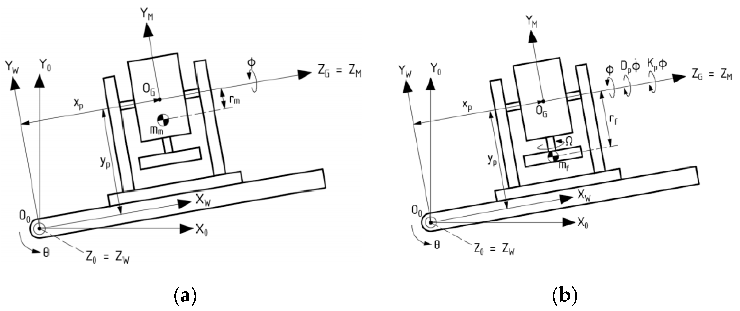
3.1. Dynamic Analysis of Gyroscopic Modeling System

The modeling concept of gyroscopic hand tremor suppression is shown in Figure 3. It consists of a hand rotating about the wrist joint axis and a gimbal structure that contains a precession axis. To depict the movement, four coordinates are defined as follows.
The inertial coordinate { O } : X 0 Y 0 Z 0 with an origin at the central point of the wrist joint; Z 0 coincides with the wrist joint axis, and Y 0 coincides with the gravity force.
The coordinate attached to a hand { W } : X W Y W Z W located at a central point of the wrist joint; Z w coincides with Z 0 and deviates at θ angle from X 0 Y 0 Z 0 .
The gimbal frame { G } : X G Y G Z G has a precession axis Z intersecting with the Y axis at its central point ( x p , y p , z p ) .
The reference coordinate { M } : X M Y M Z M has the same central point as X G Y G Z G but deviates at a φ angle from its location
The transformation matrices among the coordinates are denoted as follows.
X G Y G Z G R W O X W Y W Z W R G W X G Y G Z G R M G X M Y M Z M
R W O = [ cos θ sin θ 0 sin θ cos θ 0 0 0 1 ] ; R G W = [ 0 0 1 0 1 0 1 0 0 ] ; R M G = [ cos φ sin φ 0 sin φ cos φ 0 0 0 1 ]
Later, the human hand is considered as a linear ruler with a mass m W , location of center of gravity (CoG), and angular velocity of hand in X W Y W Z W . A coordinate is computed according to the equations below, where K W , D W , T W p e r t denote the stiffness coefficient, damping ratio, and moment due to the oscillation acting on the hand, respectively.
p w = [ x w y w z w ] T
ω w = ω x 1 y 1 z 1 = [ 00 θ ˙ ] T
The linear velocity of the human hand model can be estimated as in Figure 4.
p ˙ w = ( p ˙ w ) r e l a t i v e + ω x 1 y 1 z 1 × p w = [ θ ˙ y w θ ˙ w w 0 ] T
where ( p ˙ w ) r e l a t i v e is relative speed, which has zero value since x W , y W , z W are fixed.
The kinetic energy of the hand is:
T w = 1 2 m w p ˙ w 2 + 1 2   ω w T [ I x w 0 0 0 I y w 0 0 0 I z w ] ω w = 1 2 m w ( x 2 + y 2 ) . θ ˙ 2 + 1 2 I z w θ ˙ 2
The gravity component can be computed from the transformation of CoG into X 0 , Y 0 , Z 0 . Consequently, the potential energy includes the gravity component and the stiffness of the hand wrist.
p w X 0 Y 0 Z 0 = R 1 T p w = [ x w cos θ y w sin θ x w sin θ + y w cos θ z w ] T
V w = m w g Y 0 w + 1 2 K w θ 2 = m w g ( x w sin θ + y w cos θ ) + 1 2 K w θ 2
Therefore, the Lagrange equation of the hand is:
L w = T w V w = 1 2 [ m w ( x 2 + y 2 ) + 1 2 I z w ] θ ˙ 2 m w g ( x w sin θ + y w cos θ ) 1 2 K w θ 2
Then, for the driving motor, as shown in Figure 5a, which consists of the mass m m , its CoG location on Z M is r m in X M , Y M , Z M . In total, the coordinate of CoG and angular velocity of the motor are:
p m = [ x p y p z p ] T + R 2 T R 3 T [ 0 r m 0 ] T = [ x p   r m cos ϕ + y p r m sin ϕ + z p ] T
ω m = [ 0 0 ϕ ˙ ] T + R 3 R 2 ω x 1 y 1 z 1 = [ ϕ ˙ cos ϕ ϕ ˙ sin ϕ ϕ ˙ ] T
Similarly, the linear velocity of the motor is:
p ˙ m = ( p ˙ m ) r e l a t i v e   + ω x 1 y 1 z 1 × p m = [ ( r m cos ϕ + y p ) ϕ ˙ x p ϕ ˙ r m ϕ ˙ sin ϕ r m ϕ ˙ cos ϕ ] T ( p ˙ m ) r e l a t i v e   = [ 0 r m ϕ ˙ sin ϕ r m ϕ ˙ cos ϕ ] T
The kinetic energy T m and potential energy V m are:
T m = 1 2 m m p ˙ m 2 + 1 2 ω w m T [ I x m 0 0 0 I y m 0 0 0 I z m ] ω m = 1 2 m m . [ ( r m cos ϕ + y p ) 2 θ ˙ 2 + ( x p ϕ ˙ r m ϕ ˙ sin ϕ ) 2 + r m 2 ϕ ˙ 2 cos 2 ϕ ] + 1 2 I x m θ ˙ 2 cos 2 ϕ + 1 2 I y m θ ˙ 2 cos 2 ϕ + 1 2 I z m ϕ ˙ 2
p m X 0 Y 0 Z 0 = R 1 T p m = [ x p cos θ y p sin θ r m sin θ cos ϕ x p sin θ + y p cos θ + r m cos θ cos ϕ z p + r m sin ϕ ]
V m = m m g Y 0 m = m m g ( x p sin θ + y p cos θ + r m cos θ cos ϕ )
The Lagrange equation of the driving motor is then:
L m = T m V m =   1 2 θ ˙ 2 ( m m r m 2 cos 2 ϕ + 2 m m r m y p cos ϕ + m m x p 2 + I x m cos 2 ϕ + I y m sin 2 ϕ   ) + 1 2 ϕ ˙ ( m m r m 2 + I z m ) m m r m x p θ ˙ ϕ ˙ sin ϕ m m g ( x p sin θ + y p cos θ + r m cos θ cos ϕ )
As shown in Figure 5b, the flywheel that is directly connected to the motor rotates with an angular velocity Ω and mass m f , and its CoG location on Z G is r f . With K P and D P as the stiffness coefficient and damping ratio of the precession axis, the coordinate of CoG in X W , Y W , Z W and the angular velocity in X M , Y M , Z M are:
p f = [ x p y p z p ] T + R 2 T R 3 T [ 0 r f 0 ] T = [ x p r f cos ϕ + y p r f sin ϕ + z p ] T
ω f = [ 0 Ω ϕ ˙ ] T + R 3 R 2 ω x 1 y 1 z 1 = [ ϕ ˙ cos ϕ Ω + ϕ ˙ sin ϕ ϕ ˙ ] T
The linear velocity of the flywheel is:
p ˙ f = ( p ˙ f ) r e l a t i v e   + ω x 1 y 1 z 1 × p f = [ ( r f cos ϕ + y p ) θ ˙ x p θ ˙ r f ϕ ˙ sin ϕ r f ϕ ˙ cos ϕ ] T ( p ˙ f ) r e l a t i v e   = [ 0 r f ϕ ˙ sin ϕ r m f ϕ ˙ cos ϕ ] T
The kinetic energy T f , potential energy V f , and Lagrange equation of the flywheel are:
T f = 1 2 m f p ˙ f 2 + 1 2   ω f T [ I x f 0 0 0 I y f 0 0 0 I z f ] ω f = 1 2 m f [ ( r f cos ϕ + y p ) 2 θ ˙ 2 + ( x p θ ˙ r f ϕ ˙ sin ϕ ) 2 + r f 2 ϕ ˙ 2 cos 2 ϕ ] + 1 2 I x f θ ˙ 2 cos 2 ϕ + 1 2 I y f ( Ω + θ ˙ sin ϕ ) 2 + 1 2 I z f ϕ ˙ 2
p f X 0 Y 0 Z 0 = R 1 T p f = [ x p cos θ y p sin θ r f sin θ cos ϕ x p sin θ + y p cos θ + r f cos θ cos ϕ z p + r f sin ϕ ]
V f = m f g Y 0 f + 1 2 K p ϕ 2 = m f g ( x p sin θ + y p cos θ + r f cos θ cos ϕ ) + 1 2 K p ϕ 2
L f = T f V f = 1 2 θ ˙ 2 ( m f r f 2 cos 2 ϕ + 2 m f r f y p cos ϕ + m f y p 2 + m f x p 2 + I x f sin 2 ϕ ) + 1 2 ϕ ( m f r f 2 + I z f ) + Ω I y f θ ˙ sin ϕ m f r f x p θ ˙ ϕ ˙ sin ϕ m f g ( x p sin θ + y p cos θ + r f cos θ cos ϕ   ) 1 2 K p ϕ 2 + 1 2 I y f Ω 2
From Equations (9), (16) and (23), the Lagrange equation for the whole system including the wearable device as well as the human hand is:
L = L w + L m + L f
L θ ˙ = θ ˙ [ k 1 + k 2 cos 2 ϕ + k 3 sin 2 ϕ + 2 cos ϕ y p k 4 ] + r f I y f sin ϕ ϕ ˙ x f p sin ϕ k 4
d d t ( L θ ˙ ) = θ ¨ k 1 + k 2 ( θ ¨ cos 2 ϕ 2 θ ˙ ϕ ˙ cos ϕ sin ϕ ) + k 3 ( θ ¨ sin 2 ϕ + 2 θ ˙ ϕ ˙ sin ϕ cos ϕ ) + 2 y p k 4 ( θ ¨ cos ϕ θ ˙ ϕ ˙ sin ϕ ) + Ω I y f ϕ ˙ cos ϕ x p k 4
L θ = cos ϕ g k 5 + sin ϕ g k 6 + sin ϕ cos ϕ g k 4 K w θ
With,
k 1 = m w ( x w 2 + y w 2 ) + ( m m + m f ) ( x P 2 + y P 2 ) + I z w k 2 = m m r m 2 + m f r f 2 + I x m + I x f k 3 = I y m + I y f k 4 = m m r m + m f r f k 5 = m w x w + ( m m + m f ) x P k 6 = m w y w + ( m m + m f ) y P
Thus,
t ( L θ ˙ ) ( L θ ) = T W D W θ ˙
θ ¨ ( k 1 + k 2 cos 2 ϕ + k 3 sin 2 ϕ + 2 k 4 y p cos ϕ 2 θ ˙ ϕ ˙ sin ϕ [ ( k 2 k 3 ) cos ϕ + k 4 y p ] ϕ ¨ sin ϕ x p k 4 ϕ ˙ 2 x p k 4 cos ϕ + ϕ ˙ cos ϕ Ω I y f + D W θ ˙ + g ( k 5 cos θ k 6 sin θ k 4 sin θ cos θ ) + K w θ = T w
Moreover,
L ϕ ˙ = θ ˙ x p k 4 sin ϕ + ϕ ˙ k 7
d d t ( L ϕ ˙ ) = x p k 4 ( θ ¨ sin ϕ + θ ˙ ϕ ˙ cos ϕ ) + ϕ ¨ k 7
L ϕ = θ ˙ 2 [ ( k 2 k 3 ) sin ϕ cos ϕ k 4 y p sin ϕ ] + θ ˙ ϕ ˙ x p k 4 cos ϕ + cos θ sin ϕ g k 4 K p ϕ
t ( L ϕ ˙ ) ( L ϕ ) = T p D p ϕ ˙
θ ¨ sin ϕ x p k 4 + ϕ ¨ k 7 + θ ˙ 2 [ sin ϕ cos ϕ ( k 2 k 3 ) k 4 y p sin ϕ ] θ ˙ cos ϕ Ω I y f + D p ϕ ˙ cos θ sin ϕ g k 4 + K p ϕ = T p
where T w , T P are the moments on the wrist hand and precession axis, respectively.
H 2 x 2 [ θ ¨ ϕ ¨ ] + C 2 x 1 = [ T w T p ]
where H 2 x 2 = [ k 1 + k 2 cos 2 ϕ + k 3 sin 2 ϕ + 2 k 4 y P cos ϕ k 4 x P sin ϕ k 4 x P sin ϕ k 7 ]
C 2 x 1 = [ 2 θ ˙ ϕ ˙ sin ϕ [ ( k 2 k 3 ) cos ϕ + k 4 y P ] θ ˙ 2 cos ϕ k 4 x P + ϕ ˙ cos ϕ Ω I y f + g ( k 5 cos θ k 6 sin θ k 4 sin θ cos ϕ ) + K w θ + D w θ ˙ θ ˙ 2 sin ϕ [ ( k 2 k 3 ) cos ϕ + k 4 y P ] θ ˙ cos ϕ Ω I y f g k 4 cos θ sin ϕ + K P ϕ + D P ϕ ˙ ]
For the technique of feedback linearization, Equation (35) should be re-written in the state-space form. The short representation briefly includes x ˙ = f ( x , u ) with vector x = [ θ θ ˙ ϕ ˙ ] presenting the system state and input vector u ,
u = u e q + δ u = [ T w e q T p e q ] + [ T w p e r t 0 ] = [ T w T p ]
where T w e q , T P e q are torques to balance between the gravity force on the wrist hand axis and precession axis, T w p e r t is the input tremor torque on the wrist hand axis.
In this time, the system x ˙ = f ( x , u ) and y = g ( x , u ) locally linearizes around the point ( x e q , u e q )
δ x ˙ = A δ x + B δ u
δ y = C δ x + D δ u
A = δ f δ x ( x e q , u e q )   B = δ f δ u ( x e q , u e q )   C = δ g δ x ( x e q , u e q )   D = δ g δ u ( x e q , u e q )
The equilibrium point of this system is located at x e q = [ 0 0 0 0 ] when it tremors in a resting state. From this result, x ˙ must be zero, x e q and u e q should satisfy f ( x e q , u e q ) = 0 . Then
T w p e r t = 0 T w e q = g ( m f x P + m m x P + m w x w ) T P e q = 0 δ y = T w p e r t
A = [ 0 1 0 0 m f g ( r f + y P ) + m w g y w + m m g ( r m + y P ) K w k 8 D w k 8 0 Ω I y f k 8 0 0 0 1 0 Ω I y f k 7 K P + g ( m m r m + m f r f ) k 7 D P k 7 ]
B = [ 0 1 k 8 0 0 ] C = [ 1 0 0 0 ] D = 0 k 8 = k 1 + k 2 + 2 k 4 y P
To verify the resemblance of the system response before and after the linearization process in a range of specific values, Figure 6 demonstrates the output response θ of this system regarding the sine input torque varying from 2 Hz to 6 Hz. It can be stated that the characteristic performance of the system model is homologous from −20° to +20°, whether it is linearized or not. In [36], the wrist hand angle in Parkinson’s patients fluctuates in a range of ±15°. Therefore, a linearization model of this system is recommended in order to investigate the effectiveness of our approach.

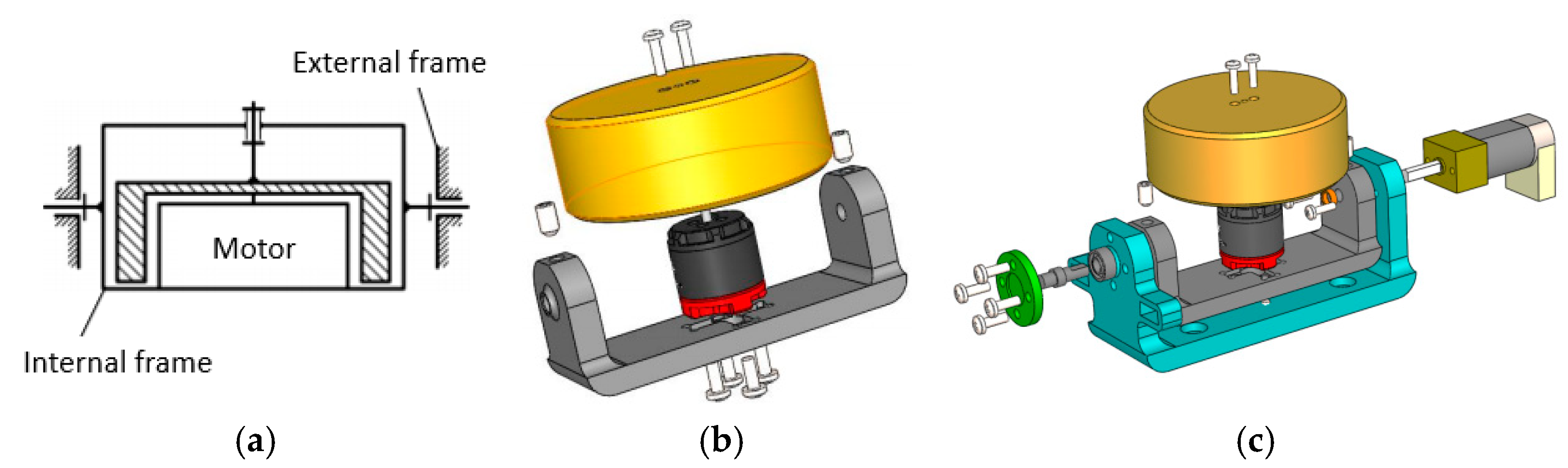
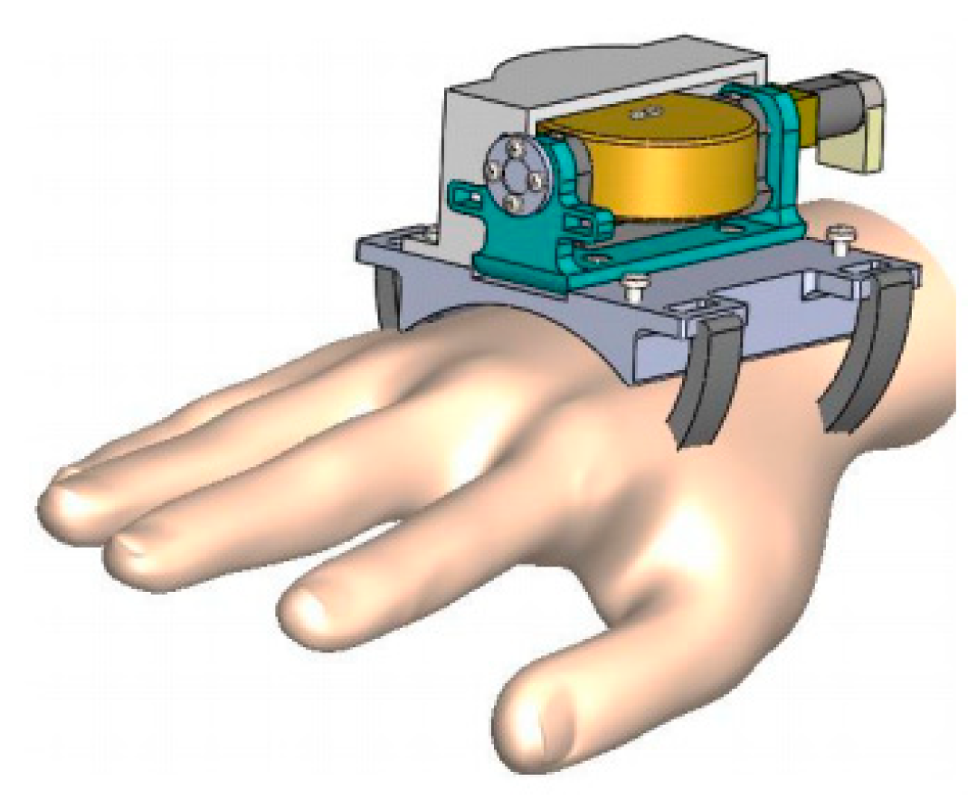
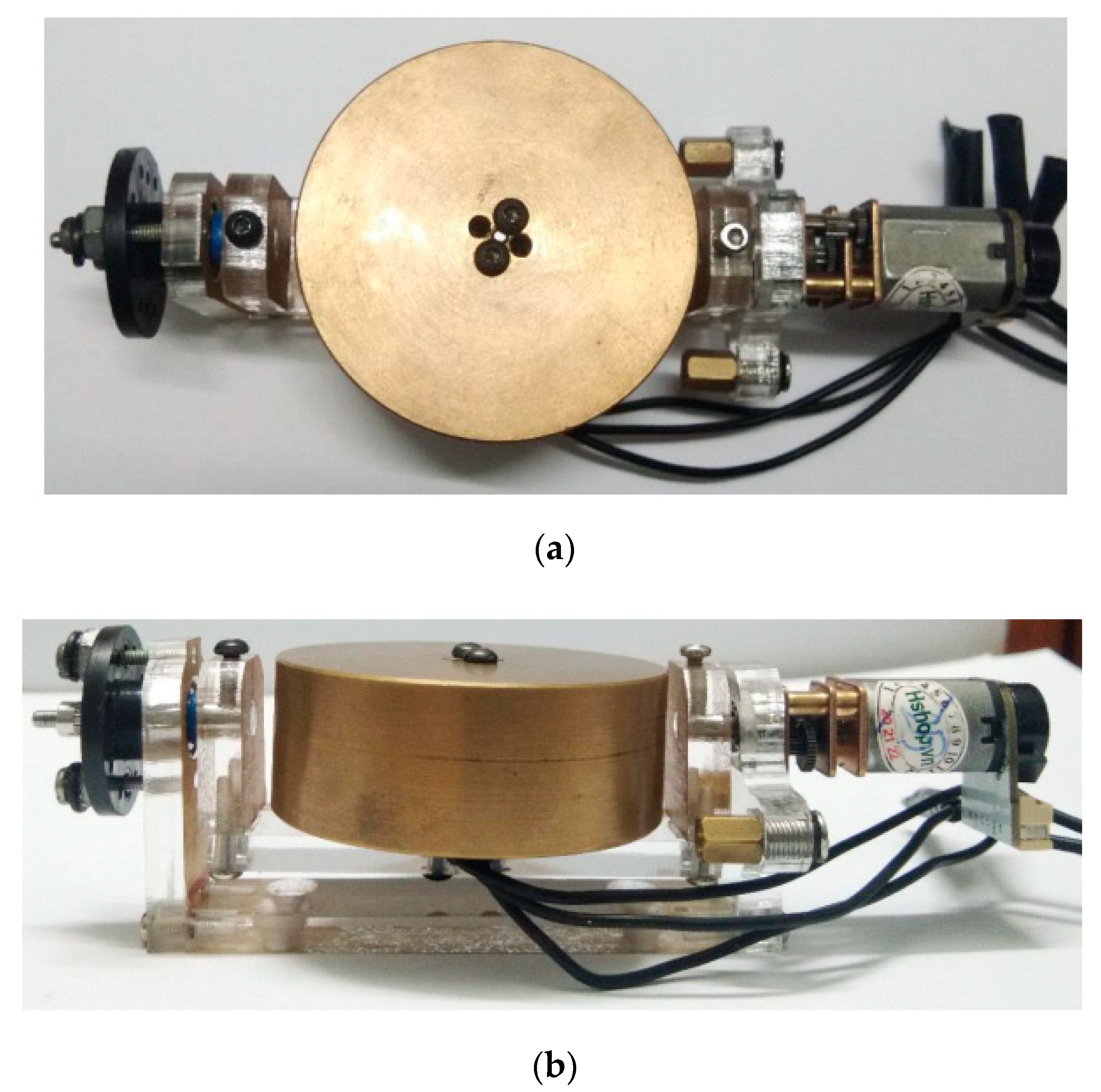
3.2. Gyroscope-Enabled Framework of Wearable Device to Suppress Vibration

The concept of this paper was to investigate a novel wearable device to suppress the uniaxial tremor on one hand of Parkinson’s patients. Based on the fundamental principle of the gyroscope, the analysis of the dynamic model was accomplished. When wearing the proposed design, a human hand with a single degree of freedom at the wrist and a gyroscope-based anti-tremor device mounted on the back of the hand become a rigid body. The system performance was validated to examine the gyroscope’s parameters and orientation, which affects tremor suppression.
From the above modeling and analysis, we were motivated to carry out a feasible and innovative design. Due to the wearable characteristic, the structure must be compact and lightweight to ensure the comfort of the patient, as shown in Figure 7. The direct connection from the flywheel to the motor gives assistance to lessen the total weight of the device. The shape of the flywheel must be symmetrical, and its material should be distributed uniformly. Later, the driving motor type might be brushless DC, since it rapidly rotates around the radial axis. Both the flywheel and motor are linked to the internal frame, which ought to be light and concentric. Moreover, it is noted that the amplitude of the vibration could be enlarged in a low-frequency zone, although it would suppress tremors in higher-frequency regions. Henceforth, to improve the system response, several control methods were considered such as precession state control [37], the extended Jacobian method [38], or approximate control [39]. In this work, we evaluated the proper approach to control the precession axis. Equation (38) could be re-written as
θ ¨ k 8 + D w θ ˙ + K w θ = T w K g ϕ ˙
ϕ ¨ k 7 + D P ϕ ˙ + K P ϕ = T P + K g θ ˙
where:
K g = I y f Ω K P = K p g ( m m r m + m f r f )
K w = K w m f g ( r f + y P ) + m w g y w + m m g ( r m + y P )
In [37], the max value of the moment on the precession axis is:
T g = k s K g θ ˙ = k s I y f Ω θ ˙ = 1.2 × 4.3 × 10 5 2500 × 2 π 60 × 1.4 = 0.019 ( Nm )
Remember that the desired velocity θ ˙ that rotates around the precession axis in a range of ± 20 o for 0.5   s , k s which is 1.4   rad / s , is the safe threshold due to the tolerance of the ball-screw, since the driving motor is attached to the mechanical part. The concept of our proposed device was simulated in three-dimensional space, as shown in Figure 8. As everyone has different hand sizes, the base should be curved and tied to the hand via a fastener.

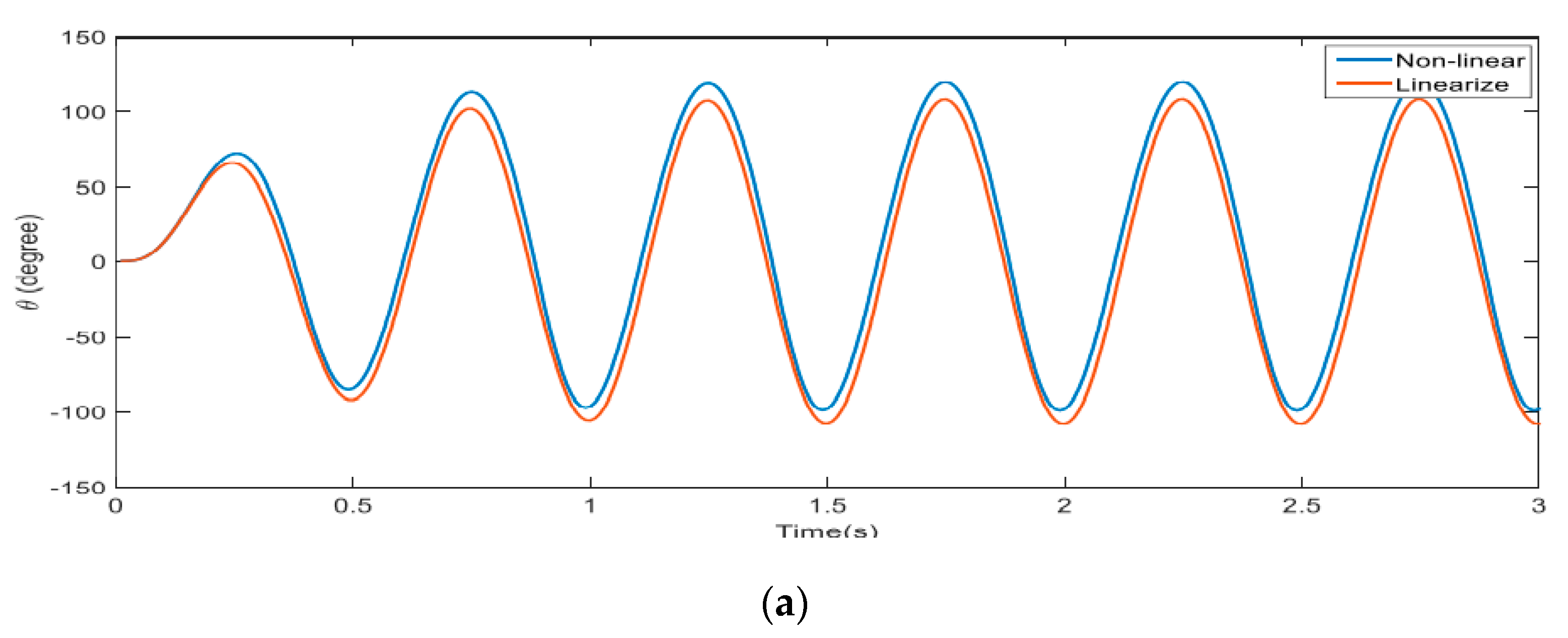
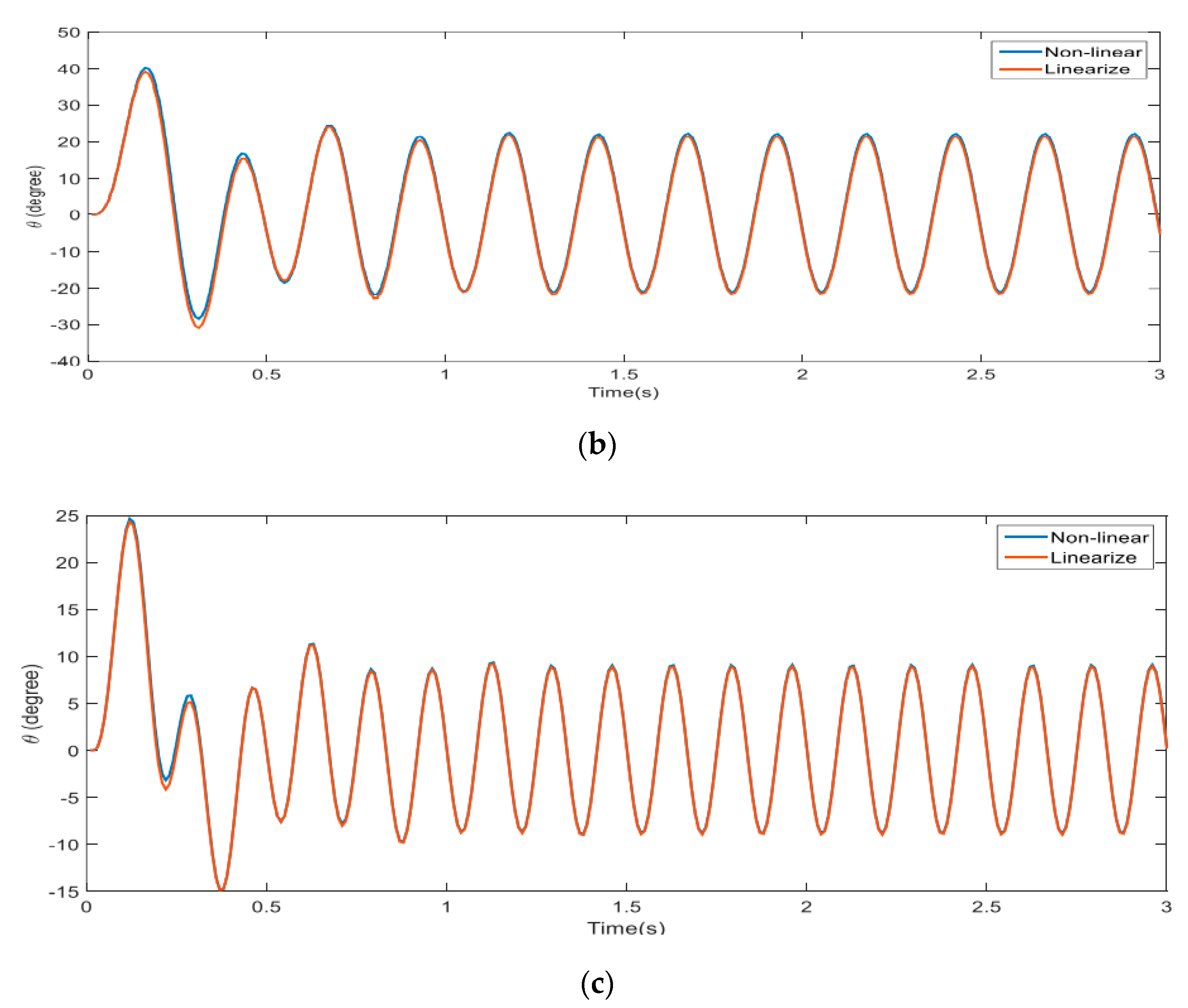
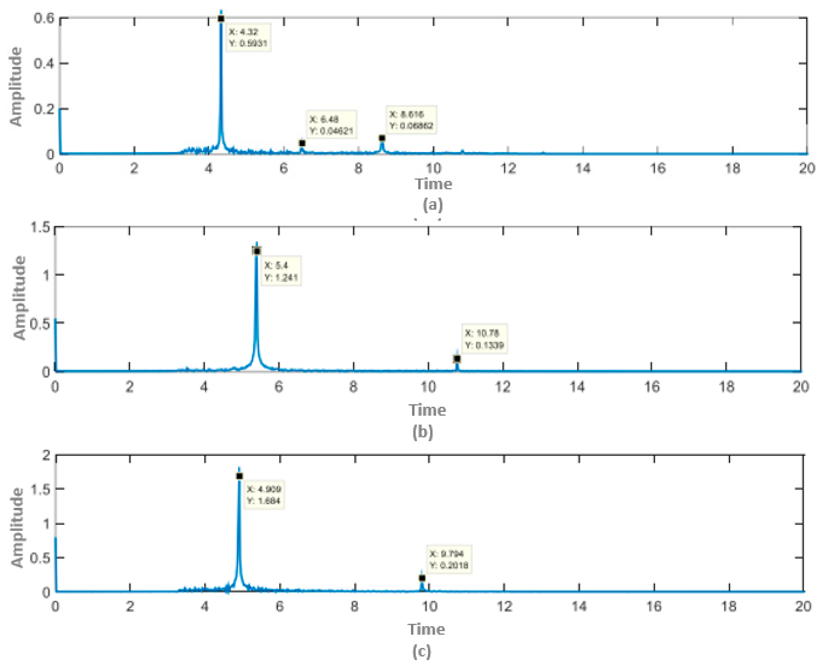
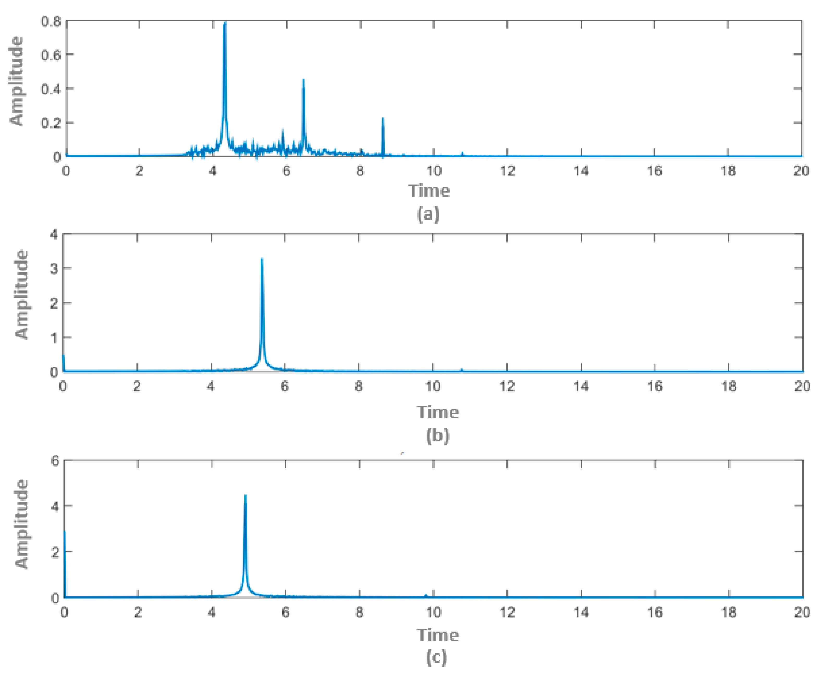
4. Results and Discussion

To verify the effectiveness of our approach, a test platform was built with our device’s hardware model in a practical situation, as shown in Figure 9. The design mentioned in the previous section was realized to investigate the gyroscope-based anti-tremor action. Generally, it is necessary to create a unit that is compact and lightweight to enable the user to carry out their normal activities in their daily lives. To measure the system’s performance precisely, sensor calibration is essential. In fact, most sensors also have corresponding tolerance in any direction. The accelerometer’s calibration process in three axes was ±1 g, while the root-mean-square value of the error was reduced to 0.10 m/s2.
Although we made an effort to produce high-quality testing equipment, it might not have simulated the exact data of Parkinson’s patients presented in the above section. Due to some mechanical limitations, this equipment was programmed to emulate the tremor in a range of 1.41 ± 2.58° and frequency from 4 to 6 Hz. The experimental setup was validated as above by a standard action, for instance, drinking water. This test’s tremor was classified into three levels—easy, medium, and complex—which were attained by an accelerometer. The detailed results are verified in Figure 10 to visualize the differences in various levels. In each type, the root-mean-square (RMS) value of the tremor was chosen for comparison. For the easy level, at the frequencies of 4.32 Hz, 6.48 Hz, and 8.62 Hz, the RMS values of an earthquake were 0.59°, 0.05°, and 0.07°, respectively. There were two considerable points in the medium range: the tremor had a 1.24° RMS value at 5.4 Hz and 0.14° at 10.78 Hz. Similarly, there was a 1.68° RMS value at 4.91 Hz and 0.2° RMS value at 9.79 Hz for hard tremors.
In an effort to validate the effective performance, the experimental scenario was compared between two cases: non-gyro and gyro-based tremor-less tests. The same levels (easy, medium, and hard) were also employed in both cases. In the non-gyro case such as that shown in Figure 11, it could be inferred that the average value of tremor amplitude was amplified while its frequency was kept constant. In detail, the amplitude varied from 0.59° to 0.78° at 4.32 Hz, from 0.05° to 0.4° at 6.48 Hz and from 0.07° to 0.17° at 8.62 Hz. At the medium level, the amplitude fluctuated from 1.24° to 2.98° and from 0.05° to 0.04° at 5.4 Hz and 10.78 Hz, respectively. The hard tremor case increased from 1.68° to 4.1° and decreased from 0.2° to 0.1° at tremor amplitudes at 4.91 Hz and 9.79 Hz, respectively. As a result, in the frequency range of 4 Hz to 9 Hz, the amplitude was enlarged, while it was lessened in the higher frequency of 9 Hz. The experimental tests on humans are illustrated in Figure 12, where the feasibility, effectiveness, and capability of our approach have been validated.
For competitive purposes, our work was compared with a device for finger tremor suppression in [40]. Different designs for the driving mechanism, controller, peripheral instrument, etc., are briefly summarized in Table 3. A wearable device for vibration suppression is a feasible solution for Parkinson’s patients who suffer severe medical problems and wish to avoid surgery. Our approach represents great advantages in being a lightweight, compact unit with a rapid response, high efficiency, and lower power consumption with respect to other devices.
The performance of the proposed device on tremor suppression was estimated. If tremor occurred not only when the Parkinson patient was resting, but also when they performed daily actions, some experimental works were designed to mimic these activities. Data were saved from patients whilst executing a task including both tremor motion and common posture. It is principal to filter the unnecessary information and obtain the correct data for the purpose of the research. Our experience is that different frequency ranges depend on various groups of elders. Considering the weight of the device and its location to be uniform and central, the measured tremor torque was evaluated as 0.012 Nm. Hence, the generated torque was sufficiently provided to counteract the actual tremor. The power transmission from the driving mechanism to the flywheel requires more precise manufacture of mechanical parts in order to avoid the un-wanted problems such as backlash and faults in mechanics. Furthermore, the driving motor should be activated as soon as tremor appears for optimizing the power consumption.

5. Conclusions

In this paper, an approach to create a wearable device to suppress unexpected tremors was described. The novel idea to design a gyroscope-based mechanism was systematically analyzed and smooth motion could be achieved. The frequency range of tremors in Parkinson’s patients varying from 4 to 6 Hz was used in this investigation. To verify the feasibility of our proposed design, both simulations and experiments were carried out; the physical size of this experimental hardware weighting 268 g was measured as 105 mm × 84 mm × 50 mm. The threshold value of the angle on the precession axis was approximately 20 degrees due to the limitations and tolerances of the mechanical design. There was a trade-off between the angle on the precession axis and effective tremor rejection. Additionally, the amplitude of the tremor could be reduced considerably if the gyroscope mode is turned on. When worn on the human body, it is small enough to feel comfortable. The effective tremor rejection of this device was up to 92.6%, so patients could perform daily activities by themselves. It is believed, based on the above results, that this work is feasible, proper, and robust in alleviating unexpected tremors when patients are in resting state.
The contributions of this paper are as follows: (1) attaining and analyzing tremor data from a group of Parkinson’s patients; (2) designing, manufacturing, and testing a novel mechanism that permits us to alleviate unexpected vibration; and (3) validating the proposed prototype using patient data in the real world.
Further work is required. First, the two-axis flywheel model that might lessen many types of tremors should be inspected. Second, with data from more sensors such as EMG signals, improved effects and a simpler calibration process could be obtained. Last but not least, advanced algorithms to predict or estimate tremors could be implemented at the hardware level.

Author Contributions

Conceptualization, H.P.V. and H.Q.T.N.; Methodology, H.P.V.; Software, H.P.V.; Validation, H.Q.T.N.; Investigation, H.Q.T.N.; Writing—original draft preparation, H.P.V.; Writing—review and editing, H.Q.T.N. All authors have read and agreed to the published version of the manuscript.

Funding

This research received no external funding.

Institutional Review Board Statement

Not applicable.

Informed Consent Statement

Not applicable.

Data Availability Statement

Data sharing is not applicable to this article.

Acknowledgments

We acknowledge the support of time and facilities from Ho Chi Minh City University of Technology (HCMUT), VNU-HCM for this study.

Conflicts of Interest

The authors declare no conflict of interest.

References

  1. Lin, A.; Zheng, W.; He, Y.; Tang, W.; Wei, X.; He, R.; Huang, W.; Su, Y.; Huang, Y.; Xie, H.; et al. Gut microbiota in patients with Parkinson’s disease in southern China. Parkinsonism Relat. Disord. 2018, 53, 82–88. [Google Scholar] [CrossRef]
  2. Liu, W.M.; Wu, R.M.; Lin, J.W.; Liu, Y.C.; Chang, C.H.; Lin, C.H. Time trends in the prevalence and incidence of Parkinson’s disease in Taiwan: A nationwide, population-based study. J. Formos. Med. Assoc. 2016, 115, 531–538. [Google Scholar] [PubMed] [Green Version]
  3. Moisan, F.; Kab, S.; Mohamed, F.; Canonico, M.; Le Guern, M.; Quintin, C.; Carcaillon, L.; Nicolau, J.; Duport, N.; Elbaz, A.; et al. Parkinson disease male-to-female ratios increase with age: French nationwide study and meta-analysis. J. Neurol. Neurosurg. Psychiatry 2016, 87, 952–957. [Google Scholar] [CrossRef] [Green Version]
  4. Gal, O.; Srp, M.; Konvalinkova, R.; Hoskovcova, M.; Capek, V.; Roth, J.; Ruzicka, E. Physiotherapy in Parkinson’s disease: Building ParkinsonNet in Czechia. Parkinson’s Dis. 2017, 2017. [Google Scholar] [CrossRef] [PubMed] [Green Version]
  5. Becker, C.; Brobert, G.P.; Johansson, S.; Jick, S.S.; Meier, C.R. Risk of incident depression in patients with Parkinson’s disease in the UK. Eur. J. Neurol. 2011, 18, 448–453. [Google Scholar] [CrossRef]
  6. Benito-Leon, J.; Bermejo-Pareja, F.; Morales-Gonzalez, J.M.; Porta-Etessam, J.; Trincado, R.; Vega, S.; Louis, E.D. Incidence of Parkinson disease and parkinsonism in three elderly populations of central Spain. Neurology 2004, 62, 734–741. [Google Scholar] [CrossRef]
  7. Kowal, S.L.; Dall, T.M.; Chakrabarti, R.; Storm, M.V.; Jain, A. The current and projected economic burden of Parkinson’s disease in the United States. Mov. Disord. 2013, 28, 311–318. [Google Scholar] [CrossRef]
  8. Tan, S.B.; Williams, A.F.; Morris, M.E. Experiences of caregivers of people with Parkinson’s disease in Singapore: A qualitative analysis. J. Clin. Nurs. 2012, 21, 2235–2246. [Google Scholar] [CrossRef]
  9. Winter, Y.; von Campenhausen, S.; Brozova, H.; Skoupa, J.; Reese, J.P.; Bötzel, K.; Eggert, K.; Oertel, W.H.; Dodel, R.; Ruzicka, E. Costs of Parkinson’s disease in eastern Europe: A Czech cohort study. Parkinsonism Relat. Disord. 2010, 16, 51–56. [Google Scholar] [CrossRef] [PubMed]
  10. Rossi, A.; Berger, K.; Chen, H.; Leslie, D.; Mailman, R.B.; Huang, X. Projection of the prevalence of Parkinson’s disease in the coming decades: Revisited. Mov. Disord. 2018, 33, 156–159. [Google Scholar] [CrossRef]
  11. Ghavami, S.; Shojaei, S.; Yeganeh, B.; Ande, S.R.; Jangamreddy, J.R.; Mehrpour, M.; Christoffersson, J.; Chaabane, W.; Moghadam, A.R.; Łos, M.J.; et al. Autophagy and apoptosis dysfunction in neurodegenerative disorders. Prog. Neurobiol. 2014, 112, 24–49. [Google Scholar] [CrossRef] [Green Version]
  12. Taheri, B.; Case, D.; Richer, E. Adaptive suppression of severe pathological tremor by torque estimation method. IEEE/ASME Trans. Mechatron. 2014, 20, 717–727. [Google Scholar] [CrossRef]
  13. Louis, E.D. Treatment of essential tremors: Are there issues we are overlooking? Front. Neurol. 2012, 2, 91. [Google Scholar] [CrossRef] [PubMed] [Green Version]
  14. Lyons, K.E.; Pahwa, R. Pharmacotherapy of essential tremor. CNS Drugs 2008, 22, 1037–1045. [Google Scholar] [CrossRef] [PubMed]
  15. Grossman, N.; Bono, D.; Dedic, N.; Kodandaramaiah, S.B.; Rudenko, A.; Suk, H.J.; Cassara, A.M.; Neufeld, E.; Kuster, N.; Tsai, L.-H.; et al. Noninvasive deep brain stimulation via temporally interfering electric fields. Cell 2017, 169, 1029–1041. [Google Scholar] [CrossRef] [Green Version]
  16. Stoker, T.B.; Torsney, K.M.; Barker, R.A. They are emerging treatment approaches for Parkinson’s disease. Front. Neurosci. 2018, 12, 693. [Google Scholar] [CrossRef] [PubMed] [Green Version]
  17. Lozano, C.S.; Tam, J.; Lozano, A.M. The changing landscape of surgery for Parkinson’s Disease. Mov. Disord. 2018, 33, 36–47. [Google Scholar] [CrossRef]
  18. Louis, E.D.; Faust, P.L.; Vonsattel JP, G.; Honig, L.S.; Rajput, A.; Robinson, C.A.; Pahwa, R.; Lyons, K.E.; Ross, G.; Borden, S.; et al. Neuropathological changes in essential tremor: 33 cases compared with 21 controls. Brain 2007, 130, 3297–3307. [Google Scholar] [CrossRef] [Green Version]
  19. Sprenger, F.; Poewe, W. Management of motor and non-motor symptoms in Parkinson’s disease. CNS Drugs 2013, 27, 259–272. [Google Scholar] [CrossRef]
  20. Laffranchi, M.; Tsagarakis, N.G.; Caldwell, D.G. Analysis and development of a semiactive damper for compliant actuation systems. IEEE/ASME Trans. Mechatron. 2012, 18, 744–753. [Google Scholar] [CrossRef]
  21. Rahnavard, M.; Hashemi, M.; Farahmand, F.; Dizaji, A.F. Designing a hand rest tremor dynamic vibration absorber using the H 2 optimization method. J. Mech. Sci. Technol. 2014, 28, 1609–1614. [Google Scholar] [CrossRef]
  22. Taheri, B.; Case, D.; Richer, E. Robust controller for tremor suppression at a musculoskeletal level in human wrist. IEEE Trans. Neural Syst. Rehabil. Eng. 2013, 22, 379–388. [Google Scholar] [CrossRef] [PubMed]
  23. Zhou, Y.; Naish, M.D.; Jenkins, M.E.; Trejos, A.L. Design and validation of a novel mechatronic transmission system for a wearable tremor suppression device. Robot. Auton. Syst. 2017, 91, 38–48. [Google Scholar] [CrossRef]
  24. Dideriksen, J.L.; Laine, C.M.; Dosen, S.; Muceli, S.; Rocon, E.; Pons, J.L.; Benito-Leon, J.; Farina, D. Electrical stimulation of afferent pathways for the suppression of pathological tremor. Front. Neurosci. 2017, 11, 178. [Google Scholar] [CrossRef]
  25. Herrnstadt, G.; Menon, C. Admittance-based voluntary-driven motion with speed-controlled tremor rejection. IEEE/ASME Trans. Mechatron. 2016, 21, 2108–2119. [Google Scholar] [CrossRef]
  26. Tremor Fact Sheet|National Institute of Neurological Disorders and Stroke (nih.gov). May 2017. Web. 11 November 2018. Available online: https://www.ninds.nih.gov/disorders/patient-caregiver-education/fact-sheets/tremor-fact-sheet (accessed on 12 April 2021).
  27. Lenka, A.; Louis, E.D. Revisiting the clinical phenomenology of “cerebellar tremor”: Beyond the intention tremor. Cerebellum 2019, 18, 565–574. [Google Scholar] [CrossRef]
  28. Elble, R.J. Defining dystonic tremor. Curr. Neuropharmacol. 2013, 11, 48–52. [Google Scholar] [PubMed] [Green Version]
  29. Haubenberger, D.; Hallett, M. Essential tremor. N. Engl. J. Med. 2018, 378, 1802–1810. [Google Scholar] [CrossRef]
  30. Niemann, N.; Jankovic, J. Botulinum toxin for the treatment of hand tremors. Toxins 2018, 10, 299. [Google Scholar] [CrossRef] [PubMed] [Green Version]
  31. Schneider, S.A.; Edwards, M.J.; Mir, P.; Cordivari, C.; Hooker, J.; Dickson, J.; Quinn, N.; Bhatia, K.P. Patients with adult-onset dystonic tremors resembling parkinsonian tremors have scans without evidence of dopaminergic deficit (SWEDDs). Mov. Disord. Off. J. Mov. Disord. Soc. 2007, 22, 2210–2215. [Google Scholar] [CrossRef]
  32. Anouti, A.; Koller, W.C. Tremor disorders. Diagn. Manag. West. J. Med. 1995, 162, 510. [Google Scholar]
  33. Lin, Y.; Ling, B.W.K.; Xu, N.; Lam, R.W.K.; Ho, C.Y.F. Effectiveness analysis of bio-electronic stimulation therapy to Parkinson’s diseases via joint singular spectrum analysis and discrete fourier transform approach. Biomed. Signal Process. Control 2020, 62, 102131. [Google Scholar] [CrossRef]
  34. Beuter, A.; Titcombe, M.S.; Richer, F.; Gross, C.; Guehl, D. Effect of deep brain stimulation on amplitude and frequency characteristics of rest tremor in Parkinson’s disease. Thalamus Relat. Syst. 2001, 1, 203–211. [Google Scholar] [CrossRef]
  35. Riviere, C.N.; Thakor, N.V. We are modeling and canceling tremors in human-machine interfaces. IEEE Eng. Med. Biol. Mag. 1996, 15, 29–36. [Google Scholar] [CrossRef]
  36. Veluvolu, K.C.; Tan, U.X.; Latt, W.T.; Shee, C.Y.; Ang, W.T. Bandlimited multiple Fourier linear combiner for real-time tremor compensation. In Proceedings of the 2007 29th Annual International Conference of the IEEE Engineering in Medicine and Biology Society, Lyon, France, 22–26 August 2007; pp. 2847–2850. [Google Scholar]
  37. Zhou, Y.; Jenkins, M.E.; Naish, M.D.; Trejos, A.L. Characterization of parkinsonian hand tremor and validation of a high-order tremor estimator. IEEE Trans. Neural Syst. Rehabil. Eng. 2018, 26, 1823–1834. [Google Scholar] [CrossRef] [PubMed]
  38. Perez, T.; Steinmann, P.D. Analysis of ship roll gyrostabilizer control. IFAC Proc. Vol. 2009, 42, 310–315. [Google Scholar] [CrossRef]
  39. Simas, H.; Di Gregorio, R. A Technique Based on Adaptive Extended Jacobians for Improving the Robustness of the Inverse Numerical Kinematics of Redundant Robots. J. Mech. Robot. 2019, 11. [Google Scholar] [CrossRef]
  40. Zhou, Y.; Jenkins, M.E.; Naish, M.D.; Trejos, A.L. Development of a wearable tremor suppression glove. In Proceedings of the 2018 7th IEEE International Conference on Biomedical Robotics and Biomechatronics (Biorob), Enschede, The Netherlands, 26–29 August 2018; pp. 640–645. [Google Scholar]
Figure 1. Analysis of the amplitude of tremor versus time from patients g2 (a) and g9 (b).
Applsci 11 05026 g001
Figure 2. Analysis of a frequency range of tremors from patients g2 (a) and g9 (b).
Applsci 11 05026 g002
Figure 3. Modeling of the gyroscopic system: (a) 3D view and (b) coordinate-attached analysis.
Applsci 11 05026 g003
Figure 4. Modeling of system parameters for a human hand.
Applsci 11 05026 g004
Figure 5. Analysis of the system parameters for (a) driving motor and (b) flywheel.
Applsci 11 05026 g005
Figure 6. Illustration of system responses for input torques of (a) 2 Hz, (b) 4 Hz, and (c) 6 Hz.
Applsci 11 05026 g006aApplsci 11 05026 g006b
Figure 7. Theoretical design of the wearable device when the flywheel is directly attached to the motor (a), the internal frame of the motor–flywheel connection (b), and the 3D model showing the external frame and driving mechanism (c).
Applsci 11 05026 g007
Figure 8. The conceptual 3D design of the proposed approach.
Applsci 11 05026 g008
Figure 9. Real-world model of the proposed wearable device: (a) top view and (b) side view.
Applsci 11 05026 g009
Figure 10. Experimental results of the gyro-based tremor-less case with respect to three levels: (a) easy, (b) medium, and (c) hard.
Applsci 11 05026 g010
Figure 11. Experimental results of the non-gyro case with respect to three levels: (a) easy, (b) medium, and (c) hard.
Applsci 11 05026 g011
Figure 12. Experimental verification of the proposed wearable device (a) 1st test and (b) 2nd test (see here the shortcut at/sIKN8).
Applsci 11 05026 g012
Table 1. Review of the clinical investigation of various kinds of tremors.
Main CategoryChild CategoryDescriptionAuthor(s)Finding(s)
1. Action tremor1.1 Cerebellar tremorCauses agitation at the ends of extremities and is initiated by damage to the cerebellum and its pathways to other regions of the brain.Lenka, A. and Louis, E. D. [27]Via the available data, the clinical phenomenology of tremors of cerebellar origin is heterogeneous, although intention tremor is the sole signature of cerebellar lesions is an over-simplification.
1.2 Dystonic tremorOccurs due to incorrect message transfer from the brain to the corresponding muscle, causing them to be overactive.Elble, R. J. [28]There are two forms of tremor in dystonia: dystonic tremors produced by dystonic muscle contractions and tremors associated with dystonia, which is a tremor in a body part that is not dystonic, but there is dystonia elsewhere.
1.3 Essential tremorThis is one of the most frequent movement disorders. It affects the hand and can expand to the head. The shaking frequency will often decay with age, but the severity or magnitude of the tremor might increase.Haubenberger, D. et al. [29]The neurologic examination shows a postural and tremor of both hands in medium (4 to 8 Hz) from a 62-year-old woman. The tremor started slowly and symmetrically and progressed gradually.
1.4 Orthostatic tremorThis is a rare disorder consisting of erratic and rapid contractions of the legs that tend to occur when the individual is standing.Niemann, N. and Jankovic, J. [30]Drugs commonly used to treat Parkinson’s disease may also be prescribed for individuals with primary orthostatic tremors. Surgical treatment should be reserved only for the most disabling cases. Additional treatments are required.
2. Parkinsonian tremor 2.1 Resting tremorPrimarily affects an individual’s appendages, such as fingers, hands, or jaw, when they are at rest. In addition, it is also very apparent in isometric and task-specific situations.Schneider, S. A. et al. [31]Clinicians should be aware that primary adult-onset dystonia can present with an asymmetric resting arm tremor. Among patients suspected of PD, Parkinsonian tremor might be one cause.
2.2 Postural tremorOccurs when muscles are contracted, such as when maintaining part of the body at a fixed position against gravity.Anouti, A. et al. [32], Lin, Y. et al. [33]The energies of the tremor in seven patients before applying the bio-electronic stimulation therapy is higher than those after
Table 2. Personal characteristics of Parkinson’s disease patients.
PatientLevel of TremorSamples
g2Too much7176
v4Too much6282
v5Too much3400
s6Too much9114
s7Too much6264
s8Too much6216
g9Too much6354
g10Too much6180
g11Too much6306
g12Too much6360
Table 3. List of technical specifications for comparative studies.
ItemOur ApproachThe Other [40]
TypeWearableWearable
LocationWristFinger
TransmissionMechanicalCable-enabled
Driving motorDCBrushless DC
MicrocontrollerTiva-CLPC1768
Sampling rate1 kHz100 Hz
Sensor(s)03 Inertial Measurement Units05 Inertial Measurement Units
MotionFlywheelRotary-to-linear converter
Level of harmonics0303
Overall tremor amplitude reduction92.6%85%
Publisher’s Note: MDPI stays neutral with regard to jurisdictional claims in published maps and institutional affiliations.

