
Optimum Slot and Pole Design for Vibration Reduction in Permanent Magnet Synchronous Motors
by
 , , , , and
Mikel Mendizabal
1 ,
,
Alex McCloskey
1,*,
Javier Poza
2,
Sergio Zarate
2,
Jaione Iriondo
1 and
Leire Irazu
3 1
Mechanical and Manufacturing Department, Faculty of Engineering, Mondragon Unibertsitatea, Loramendi 4, 20500 Arrasate-Mondragón, Spain
2
Electronics and Computing Department, Faculty of Engineering, Mondragon Unibertsitatea, Loramendi 4, 20500 Arrasate-Mondragón, Spain
3
Mechanical Engineering, Orona Elevator Innovation Center, Orona Ideo, Jauregi Bidea s/n, 20120 Hernani, Spain
*
Author to whom correspondence should be addressed.
Appl. Sci. 2021, 11(11), 4849; https://doi.org/10.3390/app11114849
Submission received: 2 May 2021
/
Revised: 17 May 2021
/
Accepted: 20 May 2021
/
Published: 25 May 2021
(This article belongs to the Special Issue Modeling, Design and Control of Electric Machines)
Abstract
:Permanent Magnet Synchronous Motors (PMSMs) are increasingly being used and are required to satisfy noise and vibration specifications. Thus, it is necessary to develop design guidelines for electric motors that consider vibration response as a key output of the design. This work shows the influence of the main design parameters regarding PMSMs: the number of slots and the number of poles. First, the influence of the number of slots in the natural frequencies is analysed by Finite Element calculations, which are experimentally verified. Then, the analytical calculation of the vibration response is explained. This is applied for several combinations of the number of slots and the number of poles, and the results are compared. Considering the analytical development, a procedure to choose the most adequate combination of the number of slots and poles is proposed. The analytical predictions are validated according to experimental measurements in two machines.
1. Introduction
Permanent Magnet Synchronous Motors are one of the most widely used electric motor types [1], with applications in a wide range of sectors including automotive, railway transportation, and elevators, as they provide great torque capacity. However, one disadvantage is that in those applications, comfort of users is a concern, and thus, the noise and vibration generated should be low. For this reason, it is necessary to optimise the design of the electric motor, taking into account the vibration response.
The optimisation of the design of an electric machine is a very challenging task due to the consideration of multiphysics analysis [2]. In recent years, a number of research studies have been carried out to improve the design of PMSMs, analysing factors such as magnet eddy current loss, torque characteristics (average torque level, cogging torque, torque ripple, and total harmonic distortions of back EMF), radial forces, vibration, noise, and thermal issues.
Several design improvements have been proposed regarding the torque ripple or cogging torque minimisation: the shape of the magnets was optimised in [3], notches were introduced on the permanent magnets in [4], the angle of the stator tooth was improved in [5], the shape of the tip of the tooth was enhanced in [6,7], and auxiliary teeth were added in [8]. Pole and slot number combinations were also analysed in [9] to minimise the cogging torque and the Unbalanced Magnetic Force (UMF). In fact, a very low cogging torque can be obtained if the slot and pole numbers are chosen so that the Least Common Multiple (LCM) is large, as observed in [10]. The closer the number of slots () to the number of poles (p), the higher their LCM. However, a low cogging torque does not always guarantee a low torque ripple.
Regarding the reduction of vibrations and noise, the magnetisation direction of the magnets and the length of the air-gap [11], the width of the slots and the width of the tooth tip [12,13], and the shape of the magnets [14,15] were analysed. In a further investigation, the shape of the tooth, including notches [11], was studied. In addition, the influence of the yoke thickness, the tooth shape, and the radius of the junction tooth/yoke were examined to determine which of those change the mode shapes and which mode shapes are excited by electromagnetic forces [16,17].
The number of slots and the number of pole pairs are the key design parameters for the electromagnetic and vibratory performance of a PMSM [18]. They influence not only the frequencies of the excitation forces, but also which modes of vibration are excited. Comprehensive analyses of the forces together with structural and acoustic calculation procedures [19] showed that the interaction of permanent magnet field and stator slotting contributes the most to electromagnetic noise. Taking this into account, a noise reduction strategy was proposed to optimise the slot opening width. In the work of [20], the vibrations generated according to the spatial distributions of the forces were studied for several pole and slot combinations. However, concentrated forces were applied on the teeth, hence, the contributions of a significant number of harmonics were not taken into account due to spatial aliasing.
More in depth analyses of pole and slot combinations were carried out in [13,21,22,23] with significant conclusions. These authors observed that the contribution to noise of the pressure harmonic of spatial order 0 increases with the number of rotor poles. Configurations resulting in low noise were those in which low-order force harmonics were found to be weaker [21,22]. In addition, configurations with a Greatest Common Divider (GCD) of the number of slots and poles equal to 1 were not recommended due to the unbalanced magnetic force [9,10].
The dominant frequency harmonic is mainly generated by the interaction of the permanent magnet field and the armature reaction field. In contrast, the highest frequency harmonics predominantly arise from the interaction of the permanent magnet field and the permeance fluctuation [23]. It was also established that the level of magnetic vibration of the machine is mainly determined by this lowest mode of vibration. In PM machines, the order of the lowest mode of vibration excited is equal to the GCD of the number of slots and the number of poles [13].
Given the abovementioned considerations, it would seem clear that guidelines for an optimum selection of the number of slots and the number of pole pairs are required. Different authors have each proposed a distinct strategy, which, to a certain extent, are contradictory. For this reason, a clear guideline or procedure needs to be determined. In addition, the influence of the change of the number of slots and poles on the structural behaviour remains unstudied.
Therefore, the present study investigates the effect of the combination of the number of slots and pole pairs on the vibration response. To this end, the effect of the number of slots on the structural behaviour of the stator are studied. Taking into account the results of the analyses, a procedure is defined to choose the optimum combination of slots and poles. The results obtained are then verified experimentally.
First, in Section 2, the analytical and Finite Element (FE) calculations are detailed and the procedure for the experimental measurements are explained. Second, in Section 3, the results of the calculations and the measurements are given. In Section 4, the discussion of the results is presented and the procedure for the optimum design is established. Finally, in Section 5, the conclusions of the work are summarised.
2. Materials and Methods
In this section, the theoretical calculations and the procedure for the experimental analyses are presented.
First, the calculation of the magnetic pressure is explained and the spatial distribution of the pressure waves is determined according to the number of slots and poles. The vibration response calculation is then detailed, which shows the vibration modes that are excited by each spatial harmonic and, thus, which harmonics of the magnetic pressure are more sensitive to vibrations. This determines the optimum combinations of slots and poles.
In addition, the Finite Element models developed to analyse the influence of the number of slots on structural behaviour are explained.
Finally, the experimental measurements to obtain the vibration modes and natural frequencies are explained as well as the measurements of the operational vibration response.
2.1. Analytical Calculation of the Magnetic Pressure
The electromagnetic pressure is calculated from the magnetic flux density by means of the Maxwell stress tensor. The vibration response is induced by the radial pressure, hence, the tangential component of the magnetic flux density can be disregarded. The radial pressure is thus calculated as [19]
where is the radial magnetic flux with respect to the tangential position and time t, the radial pressure, and the magnetic permeability of the air. The magnetic flux is then obtained multiplying the magnetomotive force by the air-gap permeance:
where is the air-gap permeance and is the magnetomotive force. The magnetomotive force is expressed as
where is the amplitude of the kth magnetomotive force (MMF) wave and is its rotational frequency in rad/s, which is for the kth harmonic, where is the rotational frequency of the rotor in rad/s, and p is the number of pole pairs.
If the slots of the machine are taken into account, the air-gap permeance variation due to the slots must be considered, which is usually represented by a Fourier series [24,25,26,27]:
where v is the harmonic, the number of slots, the air-gap permeance without slots, and the coefficients of the Fourier series.
When the effect of the slots is included, new spatial harmonics are obtained due to the combination of the harmonics of the MMF and the slots. Therefore, the harmonics of spatial orders are obtained, in addition to the harmonics of the magnetomotive force of spatial order [13,27].
The radial pressure is obtained by Equation (1), which means that the harmonics of the magnetic flux are added to and subtracted from each other to determine the harmonics of the pressure. Thus, the harmonics of spatial distributions and are obtained for the harmonics of the magnetic flux density k and i, with the frequencies . Simplifying, this can be reduced to spatial harmonics and with frequencies .
2.2. Analytical Calculation of the Vibration Response
To analyse the effect of the design parameters, analytical calculations need to be considered. The analytical approach has proven to be a good alternative in terms of accuracy, as observed in [28,29].
As shown in Section 2.1, the electromagnetic forces are a sum of harmonic pressure waves [30]. Thus, modal superposition is applied, which involves the summation of the responses of a significant number of modes of vibration. The amplitude of vibration for each mode is determined by the excitation frequencies and natural frequencies, and on the modal participation factor. This, in turn, is subjected to the mode shapes and the pressure distributions [29,31,32]. Consequently, the mode shapes and natural frequencies of the system are required, and can be calculated either by FE calculations or analytically.
The vibration response for the radial direction is
where is the modal participation factor and is the radial mode shape of the ith mode.
As the excitation force is a sum of harmonic pressure waves (see Section 2.1), the steady-state response is also a sum of harmonic responses with a phase lag () with respect to the force
where the amplitude of the response is
where is the natural frequency, is the frequency of the kth pressure wave, is the modal damping of mode i, and is the modal force of the kth pressure wave and ith mode. To account for axial and radial–tangential mode shapes, the subscripts i are changed to , with n denoting the radial–tangential mode order and m the axial mode order.
Considering the stator as a cylinder [29,31,32], for the radial pressure and the radial mode shape , the modal force is obtained as
where , , and are the mode components of the radial, tangential, and axial vibrations, and , h, and a the equivalent density, thickness, and radius of the stator [29,31,32].
The modal shape functions can be assumed to be the same as for a cylindrical shell:
Entering the mode shapes for the fix ends case in Equation (10) [29]:
where , , and are the amplitudes of the mode shapes. The equation can be written in terms of one of them, so that the result depends on that arbitrary amplitude, which vanishes when substituted into Equations (6) and (9). If the boundary conditions were those of free ends or any other case different to that of the fixed ends, the constant term of the equation changes but a similar expression is obtained. The fixed ends condition is taken into consideration due to the assumption of stiff end-plates on both sides of the stator.
As outlined in Section 2.1, the magnetic flux density in Equation (5) introduced in Equation (1) gives the pressure as the sum of the pressure waves:
where is the amplitude of the pressure, is the rotational frequency of the pressure, and is the wave number.
For each radial–tangential (n) and axial (m) mode, and each pressure component , the amplitude is obtained. This amplitude depends on the shape of the modes and the spatial distribution of the pressure waves. From Equation (9), it is concluded that the amplitude of the vibration response equals zero when . In any other case, the integral with respect to the tangential direction is 0.
In the case of fixed ends, for and odd values of m, the value is
This amplitude is introduced in Equation (8), with the corresponding natural frequency () and excitation frequency (), and the amplitude of the vibration response is obtained.
2.3. Finite Element Calculations of the Natural Frequencies
Several models were proposed to obtain the natural frequencies and vibration modes in electric motors. These machines are composed of many elements; however, to analyse the influence of the number of slots and poles, only the stator and windings are taken into account, since the shaft and rotor are considered negligible [33,34].
As the stator is comprised of a pack of several steel sheets, orthotropic equivalent material properties have to be applied to the solid part representing the laminated stator [21,33,35,36,37,38,39]. The material properties are usually adjusted by an updating procedure in accordance with the experimental natural frequencies [21,35,36,37,38,39,40].
Windings are even more complex to model. Most researchers define a solid part of the volume of material representing the windings [18,21,22,37,39,40,41] to account for the mass and stiffness that the windings impose. The material properties of that part are also estimated by an updating procedure in accordance with the experimental natural frequencies [37,39,40].
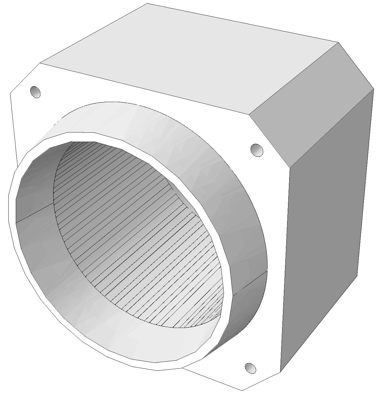
A model of the assembly of the stator and windings was used (see Figure 1), where the stator and windings are two solid parts fixed to each other.
The FE calculations were carried out using ABAQUS software. Quadratic-order reduced integration elements were used to ensure that accurate results were obtained.
2.4. Experimental Measurements
Two types of experimental measurements were carried out: (i) measurement of the natural frequencies, in which the structure is excited by an external force and the vibration response measured; (ii) operational vibration response measurements, to obtain the vibration response of the motor due to its exciting forces.
2.4.1. Measurement of the Natural Frequencies
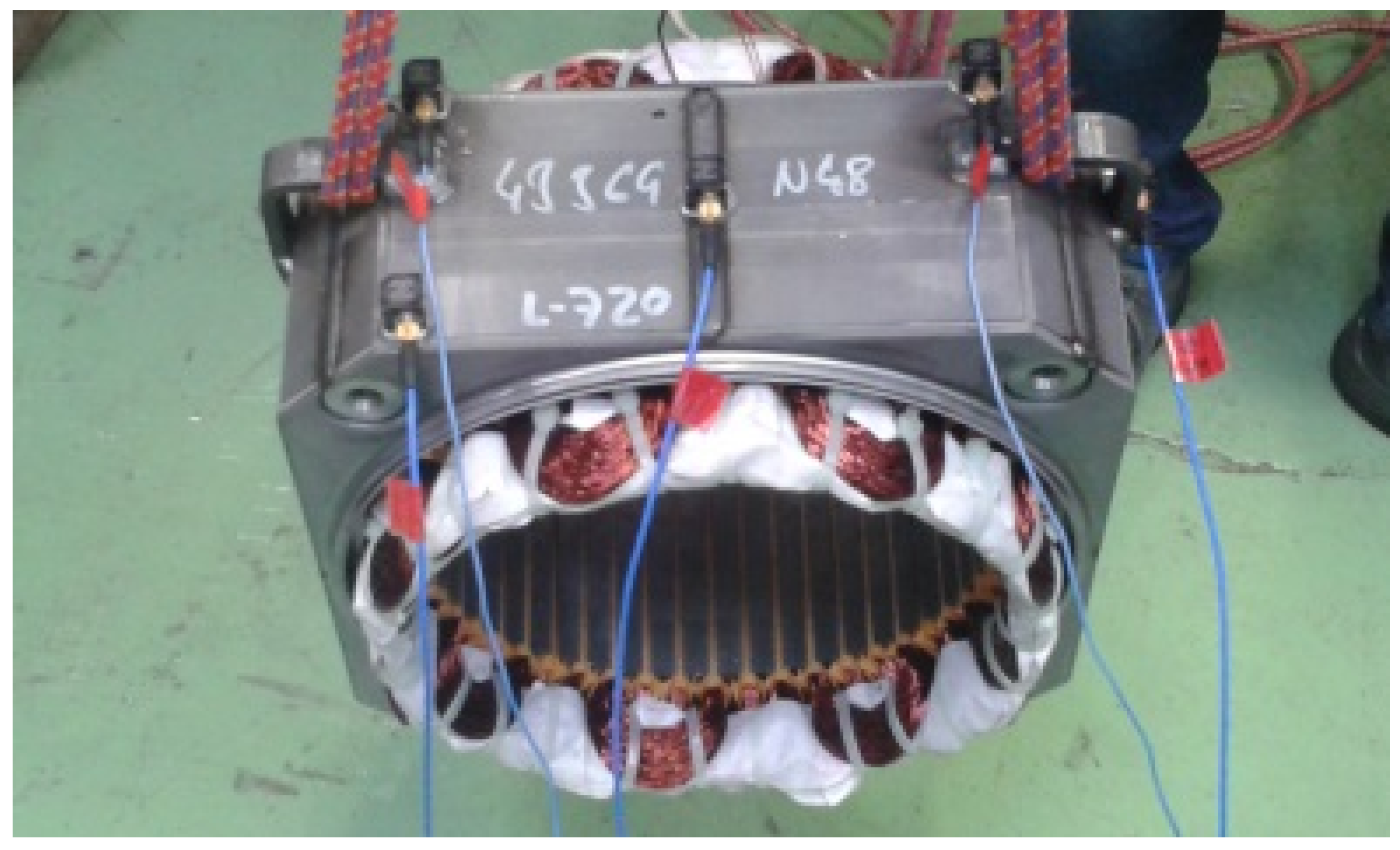
The natural frequencies of the stator were experimentally measured, exciting the system suspended by rubber bands with an impact hammer, as shown in Figure 2.
The equipment used for the measurements is as follows:
- Acquisition system Pulse Brüel & Kjær Front-end type 3560C and a laptop with Pulse Labshop software.
- An ICP impact hammer of Brüel & Kjær 8206-003 with a plastic tip (with a maximum frequency of 2000 Hz).
- 5 ICP triaxial accelerometers of PCB 356A16 (available frequency range from 0.5 Hz to 5000 Hz).
2.4.2. Measurement of the Vibration Response
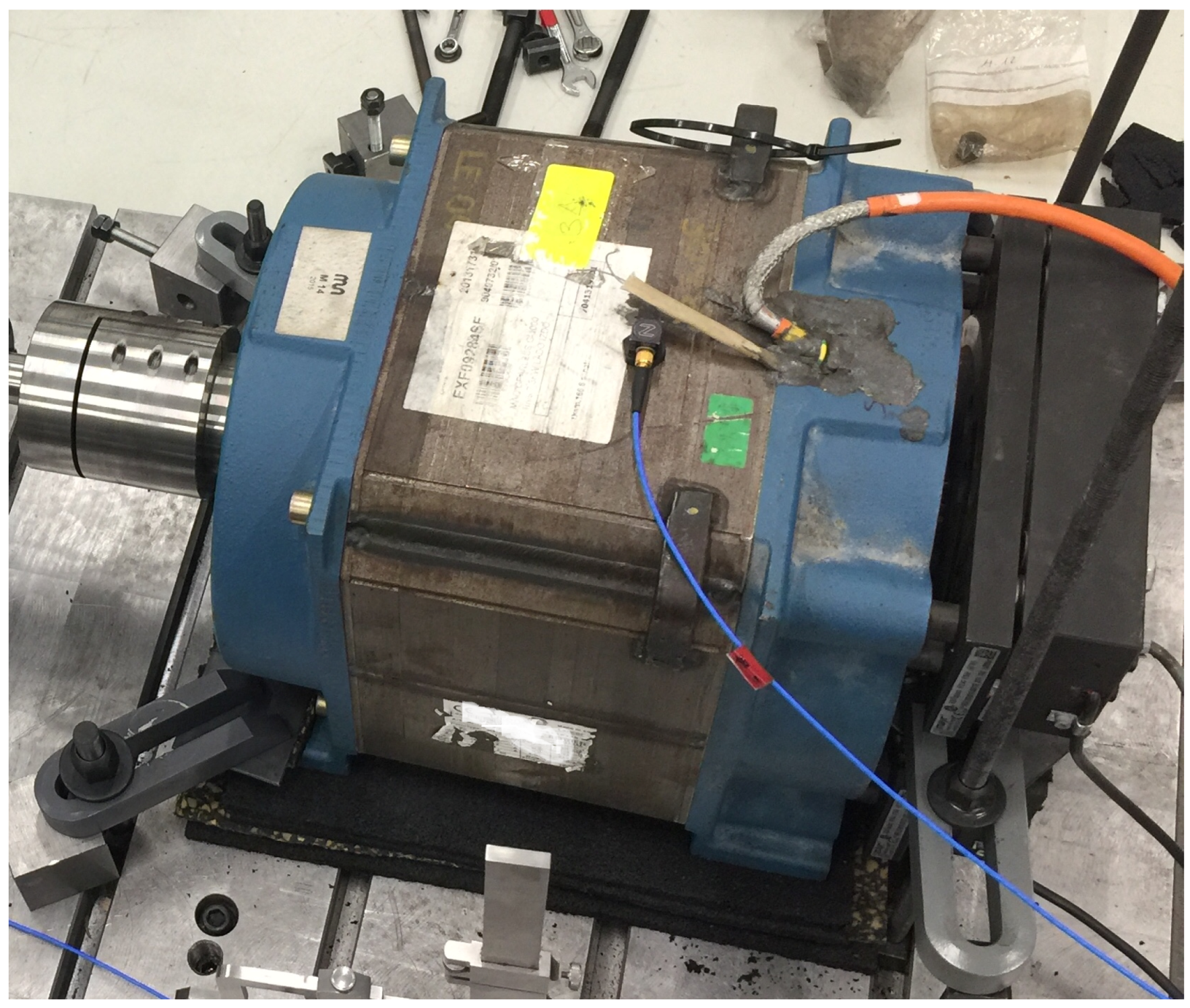
The vibration response was measured with the machines fixed, as shown in Figure 3, with the accelerometers placed on the outer faces.
The equipment employed for the measurements were as follows:
- Acquisition system Pulse Brüel & Kjær Front-end type 3560C and a laptop with Pulse Labshop software.
- ICP triaxial accelerometers of PCB 356A16 (available frequency range from 0.5 Hz to 5000 Hz).
2.4.3. Machines Measured
Two machines were measured: one of 18 slots and 8 pole pairs (18p8) and another of 48 slots and 8 pole pairs (48p8). The application of these machines is the elevator sector. Their characteristics are set out in Table 2.
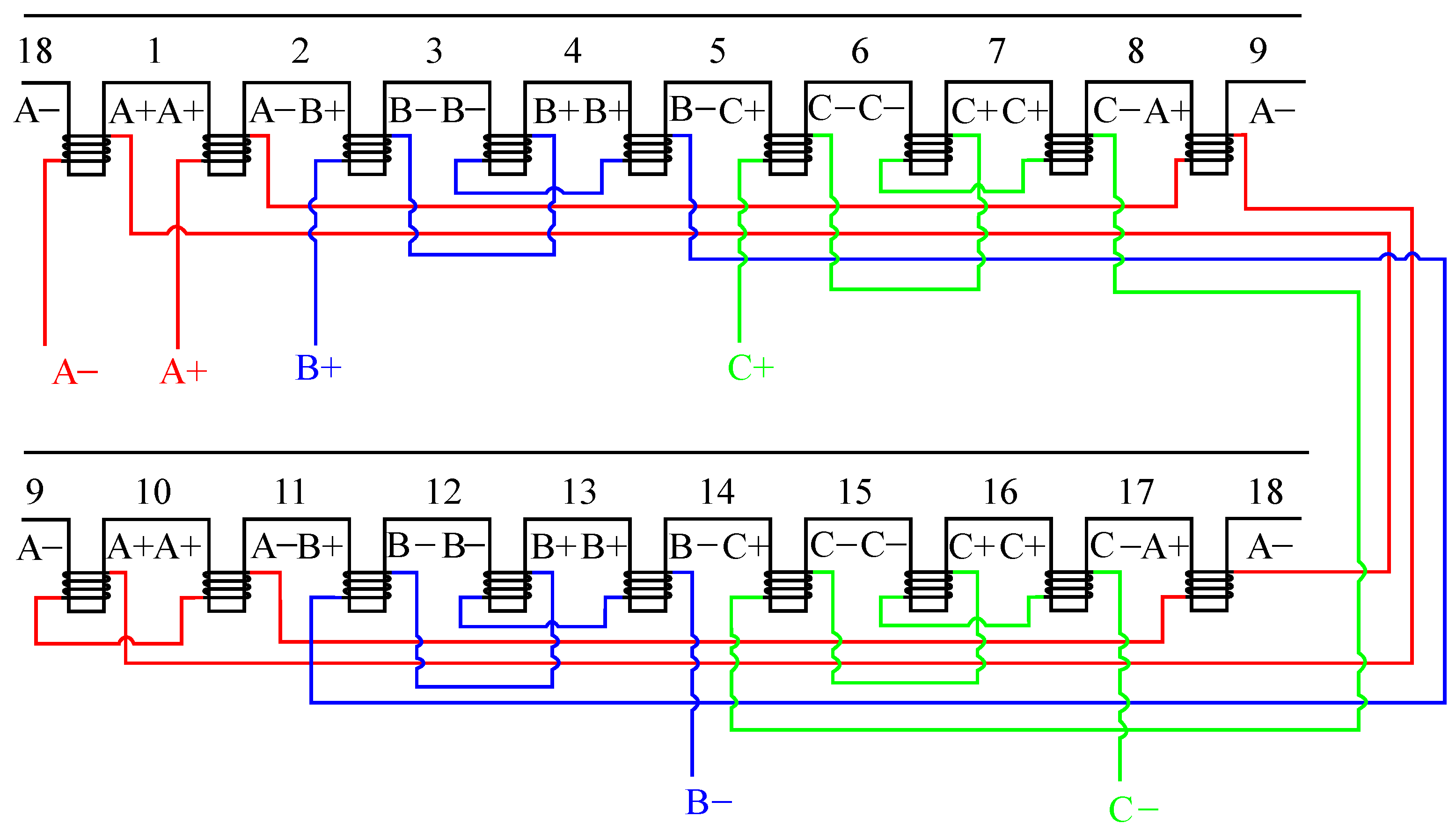
Figure 4 shows the diagram of the winding of the 18p8 machine. Each coil has 40 turns and the winding topology is a double-layer concentrated winding.
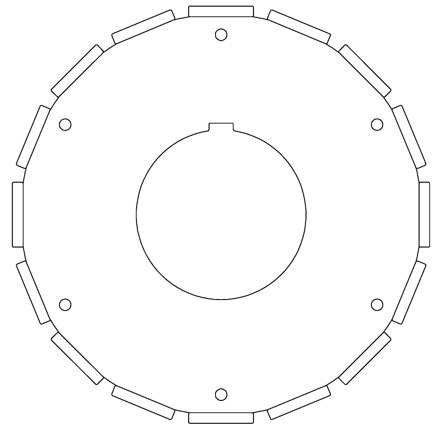
Figure 5 shows the drawing of the rotor of the 18p8 machine. It is a surface-mounted permanent magnet rotor, and the shape of the magnets is rectangular.
3. Results
In this section, the calculations and measurements carried out to analyse the influence of the number of stator slots and rotor poles are given.
First, the influence of the number of stator slots on the natural frequencies is presented. Several stators of different number of slots are analysed by Finite Element (FE) simulations and experimental measurements.
Second, the vibration response of several slot and pole combinations are calculated and rules to predict the predominant harmonics are deduced. From this, design rules for an optimised vibratory behaviour are obtained.
Finally, the analytical predictions and the design rules proposed are experimentally validated.
3.1. Analysis of the Influence of the Number of Slots on the Natural Frequencies
The natural frequencies of the assembly of the stator and the windings were calculated by means of the model defined in Section 2.3 for several numbers of teeth (or slots) of the stator. The other geometry parameters were not altered, thus, the outer shape, inner diameter, and teeth height remained unchanged. Furthermore, the number of teeth were changed but the teeth volume to slot volume ratio was kept constant. The tooth width was changed in the same proportion but inversely to the proportion at which the number of teeth is changed. For instance, if the number of teeth was doubled, the tooth width was halved.
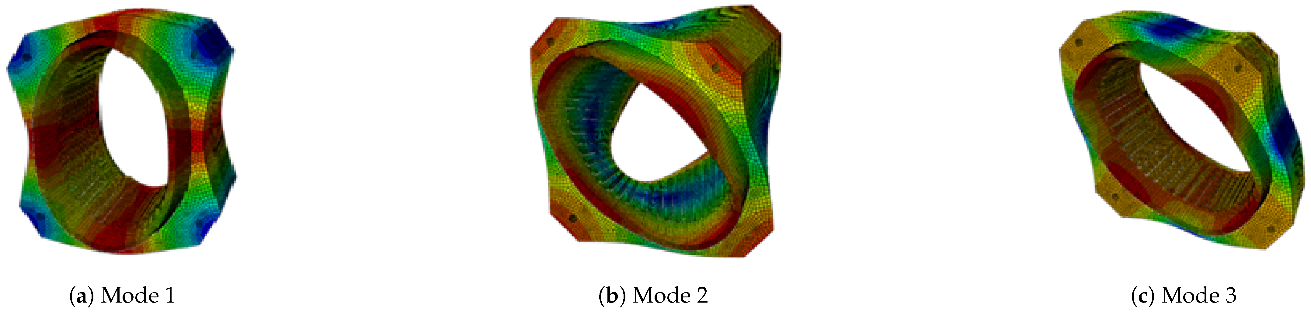
Four cases were analysed: 18, 36, 48, and 72 teeth. The first three modes in Figure 6 were compared for the abovementioned four models.
In Table 3, the results obtained are shown. In each mode, almost the same natural frequencies were obtained.
The experimental natural frequencies measured for the stators of 18 and 48 teeth are compared in Table 4.
Considering that the number of slots and the windings are not the same, and that the manufacturing process leads to a certain variability in the behaviour of individual units, the differences in natural frequencies are negligible.
3.2. Analysis of the Influence of the Number of Slots and the Number of Poles on the Vibration Response
Equations (2)–(4) determined that the spatial orders of the pressure waves are and (see Section 2.1) and, in accordance with the model shown in Section 2.2, the mode excited is of the same spatial order (n) as the pressure wave (see Equation (16)).
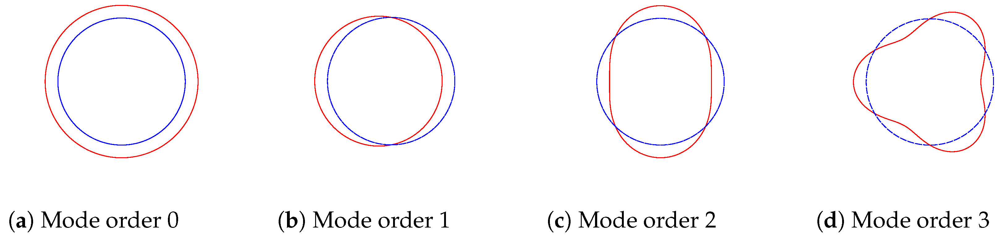
Figure 7 shows the modes of the lowest radial–tangential orders in the radial–tangential plane.
In order to identify the modes that produce a higher vibration, the lowest natural frequencies obtained by the analytical model proposed in [29] are listed in Table 5.
The above table shows that the modes of lower spatial orders have lower natural frequencies. Nevertheless, the frequencies do not increase with the order when orders 0 and 1 are considered.
Hence, the first aspect to take into account is the lowest spatial order excited , which is obtained by the Greatest Common Divider (GCD) of the number of slots () and the number of poles () [13,18,42]. The Bézout’s identity gives from . Therefore, it is suggested that should be maximised in order to reduce vibrations and noise [13,18]. However, not only does the mode order excited has to be taken into account. The amplitude of the harmonic exciting that mode must also be considered, which is of lower amplitude for higher harmonics.
In addition, the radial forces of the 0th spatial order are often significant, as is the vibration response that they may also induce [42]. Therefore, the main vibration peaks arise when the lowest vibration mode order () and the 0th mode order (breathing mode) are excited. Thus, by taking into account the harmonics which excite those mode orders, it is possible to determine the harmonics which induce the highest vibrations.
The harmonics of the magnetic pressure k and the slots v that induce the highest vibration peaks can be calculated by the equation :
- The harmonics that excite the lowest order are obtained finding the integers k that fulfil the equation , where k the harmonic of the pressure due to the magnetomotive force can only be even.
- The harmonics that induce 0th order force, where , are those that fulfill , which is calculated with the value of the LCM. Therefore, k and v can be obtained from and .
To determine the design guidelines, a number of motors of the same dimensions but different numbers of poles and slots were compared. The width of the teeth and the slots, and the angle of the poles were changed in accordance with the number of slots and poles, to maintain the same proportions. The machines were named by the number of slots and the number of pole pairs separated by p. In Table 6 the GCD and LCM of each machine are set out, as well as the smallest harmonics of the pressure due to the magnetomotive force and slotting.
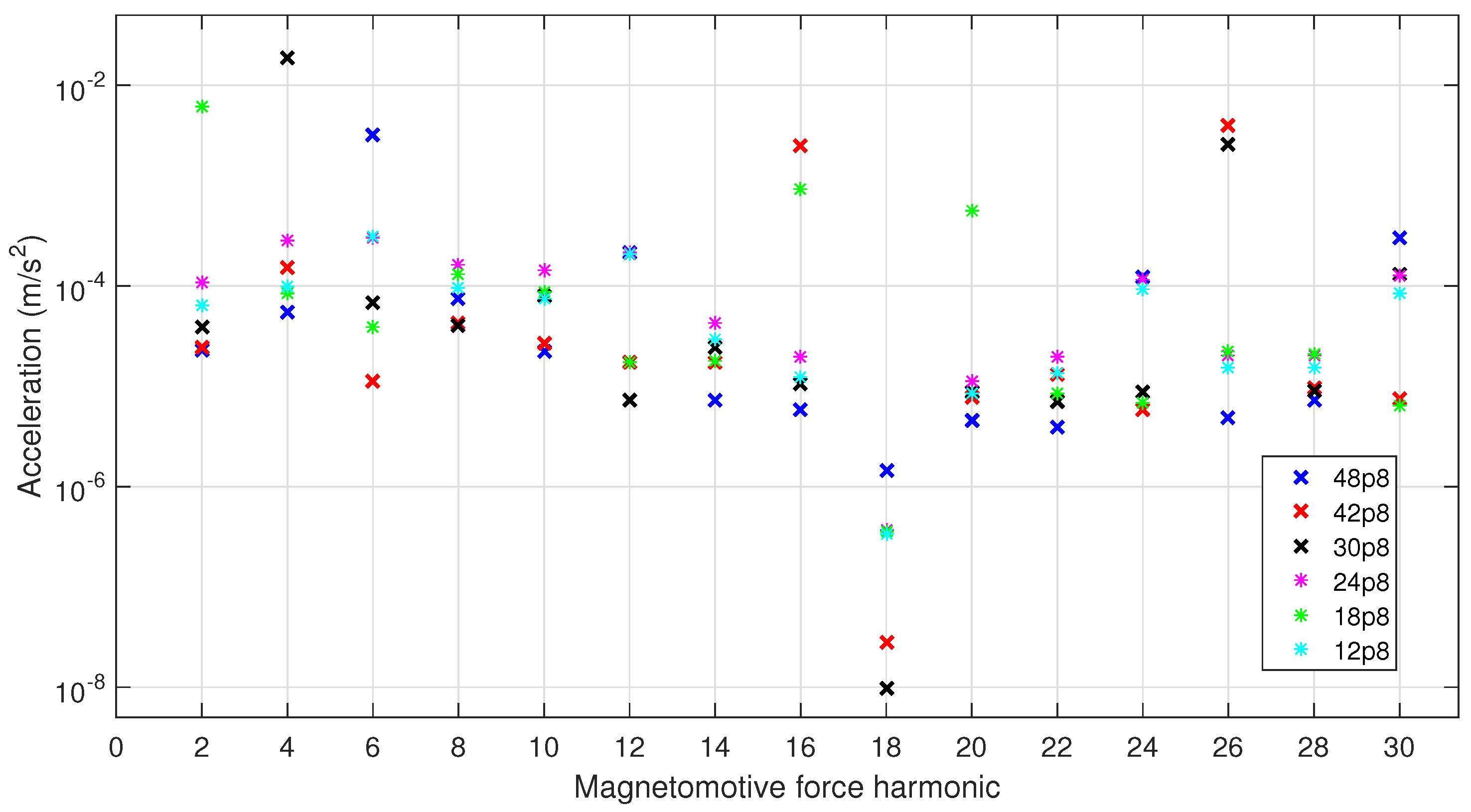
Table 6 shows that the zero-order harmonic may dominate in the machines 24p8 and 48p8. The lowest mode orders excited by those machines are 8 and 16, respectively, whose natural frequencies are significantly higher than that of the mode of 0 spatial order. The amplitude of the pressure of 0 spatial order is linked to the LCM value, which in this case is also the same. It is also linked to the slotting harmonic, which is the second harmonic in 24p8 whereas it is the first in 48p8, the latter being of higher amplitude. For this reason, the amplitude of vibration plotted in Figure 8 is lower for the 24p8 machine than for the 48p8 in the 6th harmonic and its multiples. Furthermore, other harmonics present larger amplitudes for 24p8, since the second main mode excited is the 8th instead of the 16th. Similar results are observed for 12p8; however, in this machine, the mode of order 4 may also be significant, excited by the second pressure harmonic and its multiples.
The 18p8, 30p8, and 42p8 machines have high LCM values, hence, vibrations of spatial order 0 may not be significant. However, their GCD values are low (2), and thus, the pressure harmonics that excite that mode have to be taken into account. These are the 2nd, 4th, and 16th harmonics, and give the largest vibration amplitudes.
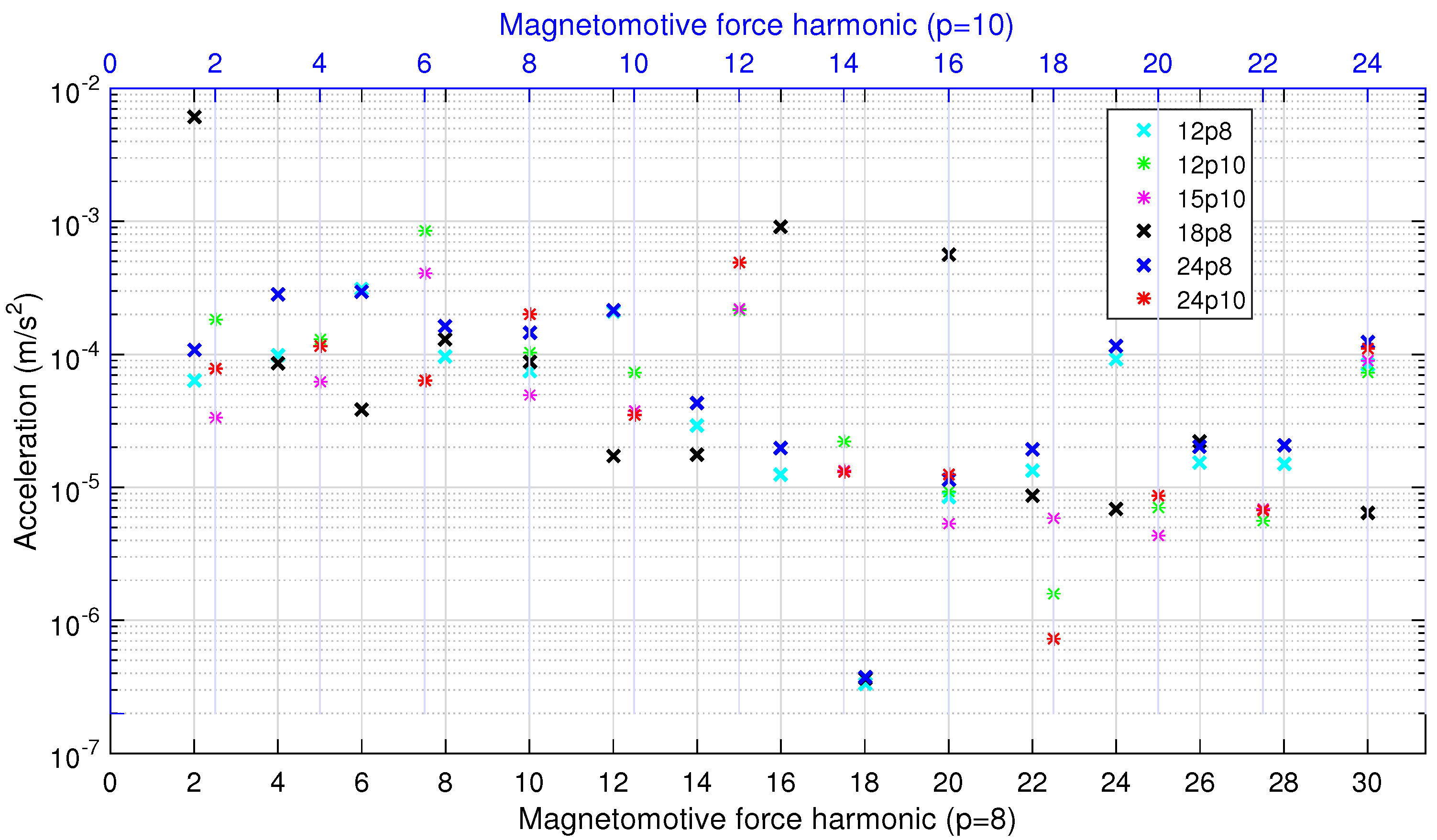
Finally, the number of poles was changed to observe their influence on vibration response. The machines compared are listed in Table 7.
The vibrations obtained are compared in Figure 9. The rotational speed is the same for all the machines; hence, the frequencies of the harmonics are different for 8 and 10 pole pairs. The main harmonics of the machines of 10 pole pairs are, for the most part, accurately predicted. The difference is significant between the 12p10 and 15p10 machines due to the lowest mode order excited, which are the 4th and 5th, respectively. Therefore, exciting a mode of higher order makes the vibration amplitudes much lower.
Regarding the comparison of the 8 and 10 pole pair machines, the amplitudes in the machines with the greater number of poles were generally found to be bigger, as were their frequencies. However, as expected, in the same frequency range, a lower number of harmonics was obtained.
3.3. Experimental Verification of the Analytical Results
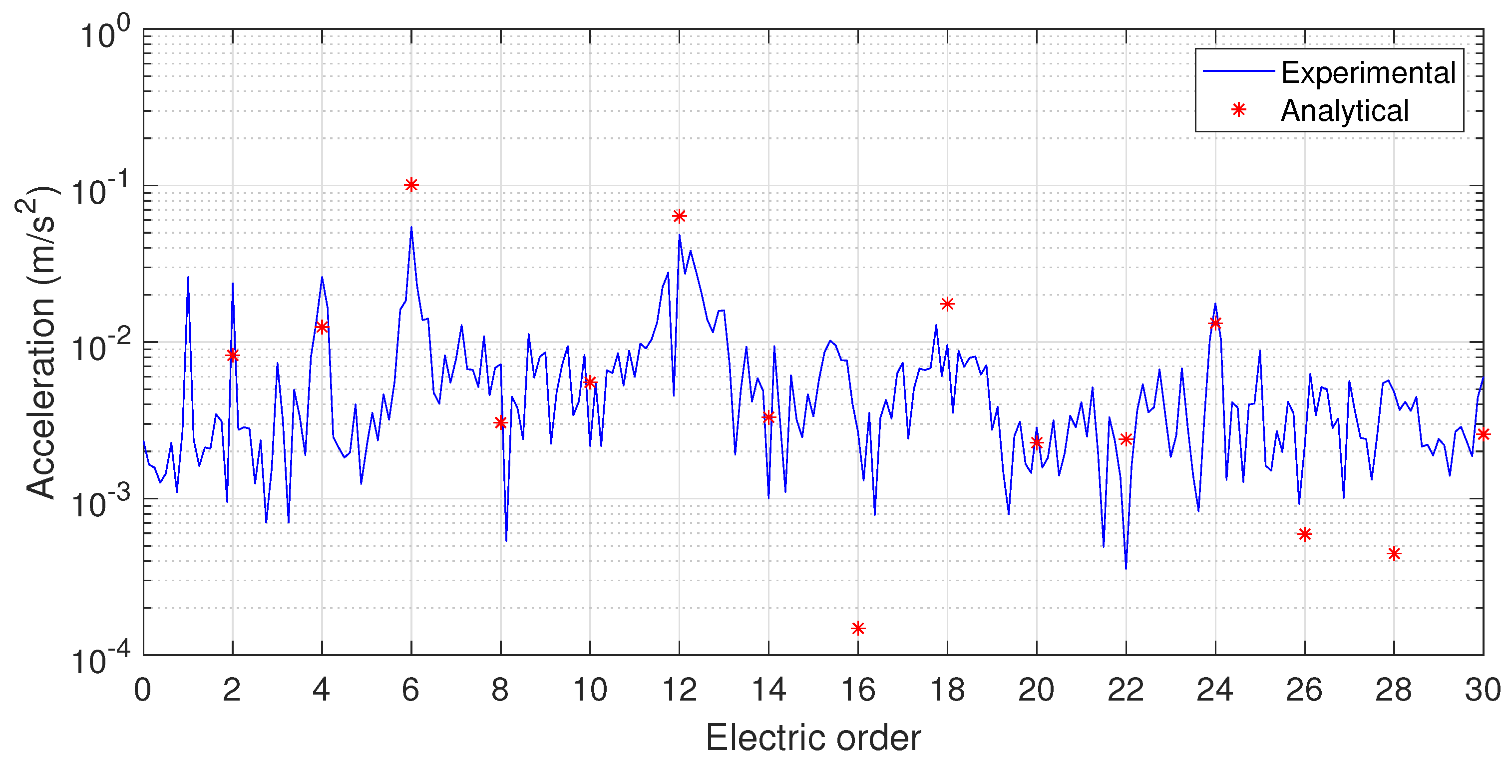
In order to verify the design rules proposed, experimental measurements of two machines were carried out. The motors measured were a 48 slot and 8 pole pair machine and an 18 slot and 8 pole pair machine (see Table 2). Figure 10 shows the comparison of the analytical calculation of the 48 slot and 8 pole pair machines with the experimental measurements. The results are in good agreement, thus, it is concluded that the main harmonics mentioned in Section 3.2 are clearly determined.
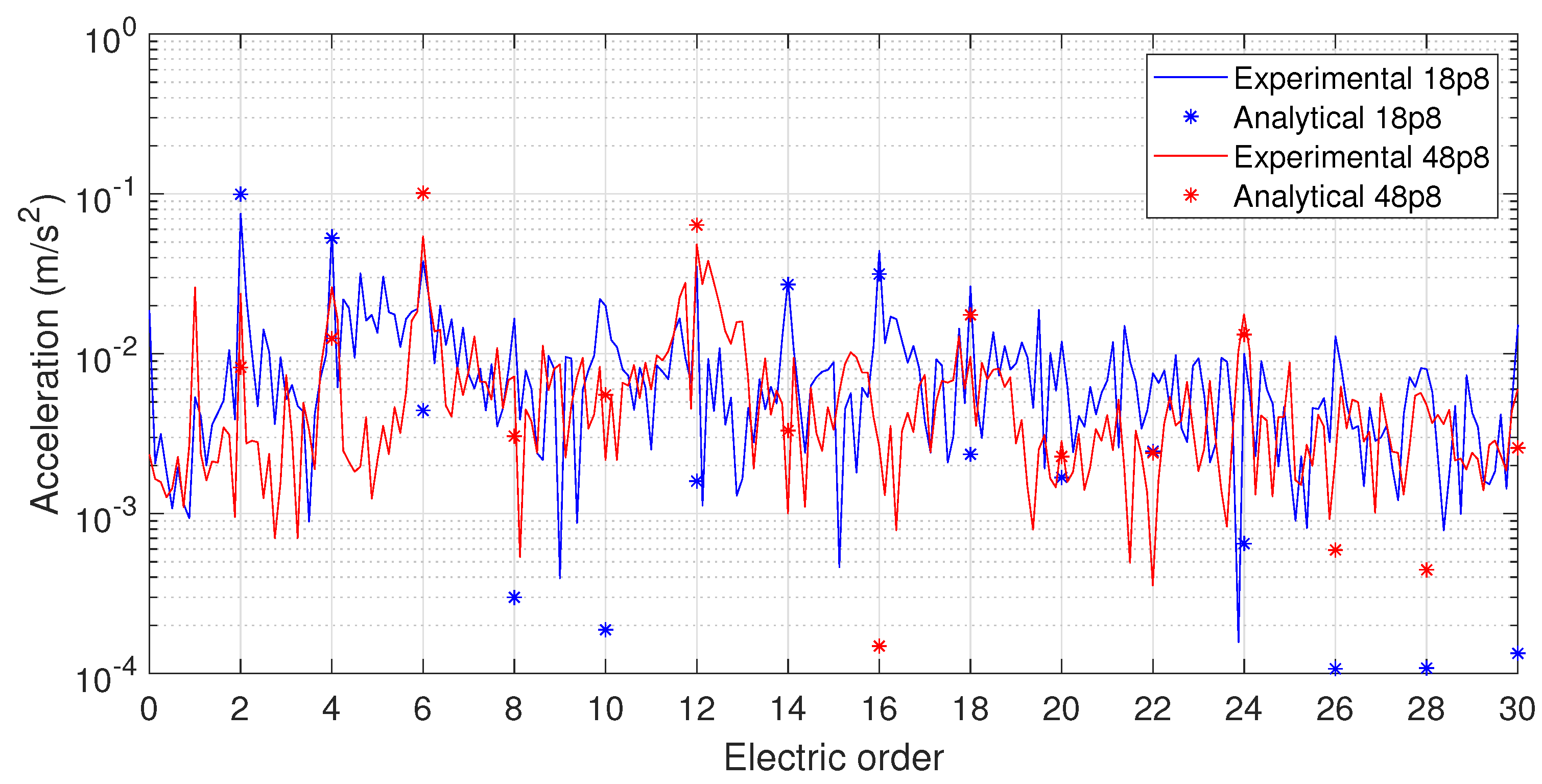
In addition, the machines of 48 slots and 8 pole pairs, and of 18 slots and 8 pole pairs are compared in Figure 11. The predominant harmonics can be clearly observed in each case: the 6th harmonic for the 48p8, which corresponds to the mode order 0 due to a low LCM value, and the 2nd harmonic for the 18p8 due to the low GCD value (see Table 6).
4. Discussion
Using the calculations and the measurement of the natural frequencies in Section 3.1, it can be concluded that the natural frequencies of the stator are roughly the same for significantly different numbers of teeth. Nevertheless, it should be noted that the diameters of the stators and the volume of teeth and windings are almost the same. It is therefore possible to change the number of slots without altering the structural behaviour, if the dimensions of the stator core and the volume of teeth and windings remain the same.
The equations given in Section 3.2 are proven to be a reliable tool to determine the harmonics of the vibration response with highest amplitudes (see Figure 11).
In order to reduce vibrations, in addition to the maximisation of , it may also be advantageous to maximise the LCM of the number of slots and the number of poles (). This is because a higher LCM means that a higher harmonic of the pressure is generating that harmonic, thus, the amplitude of that harmonic will be lower. Nonetheless, maximising and is not possible, because their product equals the product of and . For this reason, a simple design rule to choose the best numbers of slots and poles to minimise vibrations could not be determined.
Considering the results obtained (see Figure 8), it can be concluded that low GCD values and high LCM values concentrate vibrations in the harmonics that excite the lowest modes. The amplitudes of these peaks are generally higher as they correspond to a mode with a low natural frequency. In the contrary case, if GCD is high, LCM is low, and mode 0 becomes significant. Thus, the lowest mode obtained with the GCD should not be excessively high. In 24p8, the amplitudes of the harmonics were quite similar, with 8 being the order of the lowest mode excited. In the case of 48p8, mode 0 dominated, because the lowest mode was too big (16) and became insignificant. With nonexcessively big GCD values, the amplitudes are similar, therefore, the maximum amplitude obtained is minimised. Taking this into account, it is concluded that 24p8 is the best among the machines compared.
Nevertheless, depending on the application, a certain frequency range must be avoided, thus, the machine should be designed to have a few dominant peaks out of that frequency range. In this case, the GCD or the LCM should be maximised. Depending on the harmonic amplified in each of those cases and the frequency range where low vibrations are desired, the most appropriate combination can be chosen. For instance, 18p8 with a low GCD (2), which means a high amplitude of the second harmonic, can be an optimum design. If the predominant harmonic is out of the frequency range where the vibration should be low, the vibratory behaviour of that machine would be good due to the low amplitudes of most harmonics. Machine 48p8 with a low LCM also presents high amplitudes in a small number of harmonics. In this case, the sixth is the predominant harmonic, but a good performance may be possible by keeping that harmonic out of the frequency range to be avoided. In some cases, the problem is noise and, in general, low frequencies are not the main contributors. Thus, 18p8 may be a good design as the second harmonic is the predominant one. In other applications, the problem is the transmission of the vibrations to the surrounding elements and low-frequency vibrations are the most difficult to attenuate; in that case, 48p8 may be a good alternative. 18p8 and 48p8 have been measured (see Figure 11), hence, the design rules proposed are experimentally validated. These rules could prove crucial for the early design stage in which the number of slots and pole pairs are defined.
It was also observed (see Figure 9) that the increasing number of poles increased vibration amplitudes, but for the same rotational speed, presented less peaks in the same frequency range.
Finally, this study highlights the influence of the shape of the magnets or the geometry in which they are placed in the rotor on the amplitudes of the harmonics of the magnetomotive force of the magnets.
5. Conclusions
The present study analysed the main design parameters in PMSMs, the number of slots and poles, to determine their effect on vibrations. Using simple and fast calculations such as the LCM and the GCD of the number of slots and the number of poles, a significant amount of information was obtained. The harmonics to take into account in terms of vibration were determined, as was the likelihood of their amplitudes being significant.
Based on these findings, design guidelines were presented for an optimum vibratory behaviour. These propose that the highest or lowest possible GCD should be set if the vibration is required to be concentrated in one or a few harmonics. In these cases, the frequency range to be avoided should be taken into account. In the contrary case, if it is desired that the vibration is equally distributed over many harmonics, it is proposed that nonexcessively low Least Common Multiple and Greatest Common Divider values are chosen.
The results were validated with experimental measurements of the natural frequencies and the vibration response carried out in several machines.
The main limitation of the procedure proposed in this study is that the amplitudes are unknown. In some cases, it is not possible to know which of the predominant harmonics of two machines will be larger. Another limitation is that changing the number of slots may require a different winding, therefore, some characteristics of the motor may change significantly.
A more in-depth optimisation of the design is possible when the worst harmonic is identified. In changing the shape of the magnets, the amplitudes of the harmonics of the magnetomotive force may change, thus, the amplitude of the harmonics with the highest amplitudes could be reduced. In addition, the design rules proposed consider only the vibratory behaviour, and changes in electromagnetic performance should be analysed. It is therefore a subject of future work to establish design guidelines to optimise vibrations together with the electromagnetic performance such as the torque.
Author Contributions
Conceptualization, M.M. and A.M.; methodology, A.M. and J.P.; validation, J.P., S.Z. and J.I.; investigation, A.M. and S.Z.; resources, L.I.; data curation, M.M.; writing—original draft preparation, M.M.; writing—review and editing, A.M.; visualization, J.I.; supervision, J.P.; project administration, L.I.; funding acquisition, A.M. and L.I. All authors have read and agreed to the published version of the manuscript.
Funding
This research was funded by Ekonomiaren Garapen eta Lehiakortasun Saila, Eusko Jaurlaritza, grant number ZL-2018/00503 and ZL-2019/00554 and by Orona EIC.
Conflicts of Interest
The authors declare no conflict of interest.
Abbreviations
The following abbreviations are used in this manuscript:
| FE | Finite Element |
| GCD | Greatest Common Divider |
| LCM | Least Common Multiple |
| MMF | Magnetomotive Force |
| UMF | Unbalanced Magnetic Force |
References
- Corović, S.; Miljavec, D. Modal analysis and rotor-dynamics of an interior permanent magnet synchronous motor: An experimental and theoretical study. Appl. Sci. 2020, 10, 5881. [Google Scholar] [CrossRef]
- Li, Y.; Lei, G.; Bramerdorfer, G.; Peng, S.; Sun, X.; Zhu, J. Machine Learning for Design Optimization of Electromagnetic Devices: Recent Developments and Future Directions. Appl. Sci. 2021, 11, 1627. [Google Scholar] [CrossRef]
- Laskaris, K.I.; Kladas, A.G. Permanent-magnet shape optimization effects on synchronous motor performance. IEEE Trans. Ind. Electron. 2011, 58, 3776–3783. [Google Scholar] [CrossRef]
- Schlensok, C.; Gracia, M.; Hameyer, K. Combined numerical and analytical method for geometry optimization of a PM motor. IEEE Trans. Magn. 2006, 42, 1211–1214. [Google Scholar] [CrossRef]
- Reichert, T.; Kolar, J.W.; Nussbaumer, T. Stator tooth design study for bearingless exterior rotor PMSM. IEEE Trans. Ind. Appl. 2013, 49, 1515–1522. [Google Scholar] [CrossRef]
- Hsu, L.Y.; Tsai, M.C. Tooth shape optimization of brushless permanent magnet motors for reducing torque ripples. J. Magn. Magn. Mater. 2004, 282, 193–197. [Google Scholar] [CrossRef]
- Seo, K.S.; Kim, Y.J.; Jung, S.Y. Stator Teeth Shape Design for Torque Ripple Reduction in Surface-Mounted Permanent Magnet Synchronous Motor. In Proceedings of the 2014 17th International Conference on Electrical Machines and Systems (ICEMS), Hangzhou, China, 22–25 October 2014; pp. 387–390. [Google Scholar] [CrossRef]
- He, Q.; Bao, X. Reducing cogging torque in permanent-magnet synchronous motors by auxiliary teeth method. In Proceedings of the IEEE 11th Conference on Industrial Electronics and Applications, ICIEA 2016, Hefei, China, 5–7 June 2016; pp. 1488–1495. [Google Scholar] [CrossRef]
- Huo, M.; Wang, S.; Xiu, J.; Cao, S. Effect of magnet/slot combination on triple-frequency magnetic force and vibration of permanent magnet motors. J. Sound Vib. 2013, 332, 5965–5980. [Google Scholar] [CrossRef]
- Meier, F. Permanent-Magnet Synchronous Machines with Non-Overlapping Concentrated Windings for Low-Speed Direct-Drive Applications. Ph.D. Thesis, School of Electrical Engineering, KTH, Stockholm, Sweden, 2008. [Google Scholar]
- Li, Y.; Li, S.; Xia, J.; Zhang, F. Noise and Vibration Characteristics Analysis on Different Structure Parameters of Permanent Magnet Synchronous Motor. In Proceedings of the 2013 International Conference on Electrical Machines and Systems (ICEMS), Busan, Korea, 26–29 October 2013; pp. 46–49. [Google Scholar] [CrossRef]
- Hallal, J.; Pellerey, P.; Marion, F.; Druesne, F.; Lanfranchi, V. Harmonic pressure optimization on numerical electric motor model. In Proceedings of the 19th International Conference on the Computation of Electromagnetic Fields COMPUMAG, Budapest, Hungary, 30 June–4 July 2013. [Google Scholar]
- Valavi, M.; Nysveen, A.; Nilssen, R.; Rolvag, T. Slot harmonic effect on magnetic forces and vibration in low-speed permanent-magnet machine with concentrated windings. IEEE Trans. Ind. Appl. 2014, 50, 3304–3313. [Google Scholar] [CrossRef]
- Van Der Giet, M.; Franck, D.; Rothe, R.; Hameyer, K. Fast-and-easy acoustic optimization of PMSM by means of hybrid modeling and FEM-to-measurement transfer functions. In Proceedings of the 19th International Conference on Electrical Machines, ICEM 2010, Rome, Italy, 6–8 September 2010; pp. 1–6. [Google Scholar] [CrossRef]
- Jang, G.H.; Lieu, D.K. The effect of magnet geometry on electric motor vibration. IEEE Trans. Magn. 1991, 27, 5202–5204. [Google Scholar] [CrossRef]
- Besbes, M.; Picod, C.; Camus, F.; Gabsi, M. Influence of stator geometry upon vibratory behaviour and electromagnetic performances of switched reluctance motors. IEE Proc. Electr. Power Appl. 1998, 145, 462–468. [Google Scholar] [CrossRef]
- Kim, H.J.; Lee, T.G.; Kwon, S.O.; Hong, J.P. Vibration Analysis According to Stator Shape Design in A PMSM. In Proceedings of the 2010 International Conference on Electrical Machines and Systems, Incheon, Korea, 10–13 October 2010. [Google Scholar]
- Verez, G.; Barakat, G.; Amara, Y.; Hoblos, G.; Recherche, D.; Electroniques, S. Impact of Pole and Slot Combination on Vibrations and Noise of Electromagnetic Origins in Permanent Magnet Synchronous Motors. IEEE Trans. Magn. 2015, 51, 18–21. [Google Scholar] [CrossRef]
- Zuo, S.; Lin, F.; Wu, X. Noise Analysis, Calculation, and Reduction of External Rotor Permanent-Magnet Synchronous Motor. IEEE Trans. Ind. Electron. 2015, 62, 6204–6212. [Google Scholar] [CrossRef]
- Islam, R.; Husain, I. Analytical model for predicting noise and vibration in permanent-magnet synchronous motors. IEEE Trans. Ind. Appl. 2010, 46, 2346–2354. [Google Scholar] [CrossRef]
- Verez, G.; Barakat, G.; Amara, Y.; Bennouna, O.; Hoblos, G. Impact of Pole and Slot Combination on Noise and Vibrations of Flux-Switching PM Machines. In Proceedings of the 2014 International Conference on Electrical Machines (ICEM), Berlin, Germany, 2–5 September 2014; pp. 182–188. [Google Scholar] [CrossRef]
- Verez, G.; Barakat, G.; Amara, Y. Influence of Slots and Rotor Poles Combinations on Noise and Vibrations of Magnetic Origins in ‘U’–Core Flux-Switching Permanent Magnet Machines. Prog. Electromagn. Res. B 2014, 61, 149–168. [Google Scholar] [CrossRef] [Green Version]
- Krotsch, J.; Piepenbreier, B. Harmonic diversity and determining factors of radial forces in external rotor permanent magnet synchronous motors with concentrated windings. In Proceedings of the 19th International Conference on Electrical Machines, ICEM 2010, Rome, Italy, 6–8 September 2010. [Google Scholar] [CrossRef]
- Yu, Y.; Bi, C.; Hla, P.N.; Jiang, Q.; Lin, S.; Aung, N.L.H.; Mamun, A.A. Incline unbalanced magnetic pull induced by misalignment rotor in PMSM. IEEE Trans. Magn. 2013, 49, 2709–2714. [Google Scholar] [CrossRef]
- Gomez, I.; Almandoz, G.; Poza, J.; Ugalde, G.; Escalada, A.J. Analytical model to calculate radial forces in permanent-magnet synchronous machines. In Proceedings of the 2014 International Conference on Electrical Machines, ICEM 2014, Berlin, Germany, 2–5 September 2014; pp. 2681–2687. [Google Scholar] [CrossRef]
- Žarko, D.; Lipo, T.A.; Ban, D. Analytical Calculation of Magnetic Field Distribution in the Slotted Air Gap of a Surface PM Motor Using Complex Relative Air Gap Permeance. IEEE Trans. Magn. 2006, 42, 1828–1837. [Google Scholar] [CrossRef]
- Zhu, Z.Q.; Wu, L.J.; Mohd Jamil, M.L. Influence of pole and slot number combinations on cogging Torque in permanent-magnet machines with static and rotating eccentricities. IEEE Trans. Ind. Appl. 2014, 50, 3265–3277. [Google Scholar] [CrossRef]
- Lecointe, J.P.; Romary, R.; Brudny, J.F.; Czapla, T. Five methods of stator natural frequency determination: Case of induction and switched reluctance machines. Mech. Syst. Signal Process. 2004, 18, 1133–1159. [Google Scholar] [CrossRef]
- McCloskey, A.; Arrasate, X.; Hernández, X.; Gómez, I.; Almandoz, G. Analytical calculation of vibrations of electromagnetic origin in electrical machines. Mech. Syst. Signal Process. 2018, 98, 557–569. [Google Scholar] [CrossRef]
- Le Besnerais, J.; Lanfranchi, V.; Hecquet, M.; Friedrich, G.; Brochet, P. Characterisation of radial vibration force and vibration behaviour of a pulse-width modulation-fed fractional-slot induction machine. IET Electr. Power Appl. 2009, 3, 197. [Google Scholar] [CrossRef] [Green Version]
- Soedel, W. Vibrations of Shells and Plates; CRC Press: Boca Raton, FL, USA, 2004. [Google Scholar]
- Wang, C.; Lai, J.C.S. The sound radiation efficiency of finite length acoustically thick circular cylindrical shells under mechanical excitation I: Theoretical analysis. J. Sound Vib. 2000, 232, 431–447. [Google Scholar] [CrossRef]
- Wang, C.; Lai, J.C.S. Vibration analysis of an induction motor. J. Sound Vib. 1999, 224, 733–756. [Google Scholar] [CrossRef]
- Dos Santos, F.L.M.; Anthonis, J.; Naclerio, F.; Gyselinck, J.J.C.; Van Der Auweraer, H.; Góes, L.C.S. Multiphysics NVH Modeling: Simulation of a Switched Reluctance Motor for an Electric Vehicle. IEEE Trans. Ind. Electron. 2014, 61, 469–476. [Google Scholar] [CrossRef]
- Van der Giet, M.; Kasper, K.; De Doncker, R.W.; Hameyer, K. Material parameters for the structural dynamic simulation of electrical machines. In Proceedings of the 2012 XXth International Conference on Electrical Machines (ICEM), Marseille, France, 2–5 September 2012; pp. 2994–3000. [Google Scholar]
- Mair, M.; Weilharter, B.; Rainer, S.; Ellermann, K.; Bíró, O. Numerical and experimental investigation of the structural characteristics of stator core stacks. COMPEL Int. J. Comput. Math. Electr. Electron. Eng. 2013, 32, 1643–1664. [Google Scholar] [CrossRef]
- McCloskey, A.; Arrasate, X.; Almandoz, G.; Hernandez, X.; Salgado, O. Vibro-acoustic finite element analysis of a permanent magnet synchronous machine. In Proceedings of the 9th International Conference on Structural Dynamics, Eurodyn, Porto, Portugal, 30 June–2 July 2014. [Google Scholar]
- Saito, A.; Nishikawa, Y.; Yamasaki, S.; Fujita, K.; Kawamoto, A.; Kuroishi, M.; Nakai, H. Equivalent orthotropic elastic moduli identification method for laminated electrical steel sheets. Mech. Syst. Signal Process. 2015, 1–22. [Google Scholar] [CrossRef]
- Van der Giet, M.; Hameyer, K. Identification of homogenized equivalent materials for the modal analysis of composite structures in electrical machines. In Proceedings of the Institution of Mechanical Engineers—9th International Conference on Vibrations in Rotating Machinery, Exeter, UK, 8–10 September 2008. [Google Scholar]
- McCloskey, A.; Arrasate, X.; Hernandez, X.; Salgado, O. Measurement and simulation of the vibroacoustic performance of an electric motor. Mech. Mach. Sci. 2015. [Google Scholar] [CrossRef]
- Martinez, J.; Belahcen, A.; Detoni, J. A 2D magnetic and 3D mechanical coupled finite element model for the study of the dynamic vibrations in the stator of induction motors. Mech. Syst. Signal Process. 2015, 66–67, 1–17. [Google Scholar] [CrossRef]
- Le Besnerais, J. Vibro-Acoustic Analysis of Radial and Tangential Airgap Magnetic Forces in Permanent Magnet Synchronous Machines. IEEE Trans. Magn. 2015, 51, 1–9. [Google Scholar] [CrossRef]
Figure 1.
FEM stator and windings model.

Figure 2.
Experimental setup of the measurement of the natural frequencies of the stator.

Figure 3.
Experimental setup of the measurement of the vibration response.

Figure 4.
Diagram of the winding of the 18p8 machine.

Figure 5.
Design of the rotor of the 18p8 machine.

Figure 6.
First three mode shapes of the assembly of the stator and windings.

Figure 7.
Lowest four mode orders. The deformed mode shape is indicated in red and the undeformed mode shape in blue.
Figure 7.
Lowest four mode orders. The deformed mode shape is indicated in red and the undeformed mode shape in blue.

Figure 8.
Comparison of the vibration response of machines of several numbers of slots and 8 pole pairs.
Figure 8.
Comparison of the vibration response of machines of several numbers of slots and 8 pole pairs.

Figure 9.
Comparison of the vibration response of machines of several numbers of poles and slots.

Figure 10.
Comparison of the vibration response of the machine with 48 slots and 8 pole pairs.

Figure 11.
Comparison of the vibration response of the machines of 18 slots and 8 pole pairs, and 48 slots and 8 pole pairs.
Figure 11.
Comparison of the vibration response of the machines of 18 slots and 8 pole pairs, and 48 slots and 8 pole pairs.


Table 1.
Material properties of the stator and the windings (Elasticity and shear moduli (, and ) are given in GPa).
Table 1.
Material properties of the stator and the windings (Elasticity and shear moduli (, and ) are given in GPa).
| Stator | 210 | 50 | 0.25 | 6 | 4.1 | 0.005 |
| Windings | 0.8 | 0.4 | 0.005 | 50 | 20 | 0.3 |
Table 2.
Characteristics of the electric motors 18p8 and 48p8.
| 18p8 | 48p8 | |
|---|---|---|
| Pole pairs (p) | 8 | 8 |
| Slots () | 18 | 48 |
| Air gap | 1 mm | 1 mm |
| Length | 100 mm | 100 mm |
| Rotor outer diameter | 220 mm | 220 mm |
| Rated speed | 300 rpm | 300 rpm |
| Maximum speed | 400 rpm | 400 rpm |
| Rated torque | 180 Nm | 160 Nm |
| Rated power | 5.7 kW | 5 kW |
Table 3.
Comparison of the first three natural frequencies (in Hz) of the stators with different numbers of teeth.
Table 3.
Comparison of the first three natural frequencies (in Hz) of the stators with different numbers of teeth.
| 18 Teeth | 36 Teeth | 48 Teeth | 72 Teeth | |
|---|---|---|---|---|
| Mode 1 | 477.62 | 469.04 | 488.38 | 463.83 |
| Mode 2 | 546.04 | 545.66 | 541.34 | 549.67 |
| Mode 3 | 717.73 | 714.98 | 724.63 | 718.80 |
Table 4.
Comparison of the first four natural frequencies (in Hz) of the stators with different numbers of teeth.
Table 4.
Comparison of the first four natural frequencies (in Hz) of the stators with different numbers of teeth.
| 18 Teeth | 48 Teeth | Difference (%) | |
|---|---|---|---|
| Mode 1 | 395.17 | 444.54 | 11.11 |
| Mode 2 | 574.03 | 561.70 | −2.20 |
| Mode 3 | 568.96 | 600.02 | 5.18 |
| Mode 4 | 631.83 | 700.06 | 9.75 |
Table 5.
Natural frequencies of the lowest radial mode orders of the assembly of the stator and windings.
Table 5.
Natural frequencies of the lowest radial mode orders of the assembly of the stator and windings.
| Mode (n,m) | (2,1) | (1,1) | (3,1) | (4,1) | (5,1) | (6,1) | (0,1) |
|---|---|---|---|---|---|---|---|
| Frequency (Hz) | 675.7 | 700.3 | 1144.5 | 1614.1 | 1881.1 | 2169.4 | 2263.4 |
Table 6.
Characteristics of the machines of 8 pole pairs.
| Machine | 12p8 | 18p8 | 24p8 | 30p8 | 42p8 | 48p8 |
|---|---|---|---|---|---|---|
| 4 | 2 | 8 | 2 | 2 | 16 | |
| 48 | 144 | 48 | 240 | 336 | 48 | |
| 2 | 2 | 2 | 4 | 16 | 4 | |
| 1 | 1 | 1 | 1 | 3 | 1 | |
| 6 | 18 | 6 | 30 | 42 | 6 | |
| 4 | 8 | 2 | 8 | 8 | 1 |
Table 7.
Parameters of the machines of 8 and 10 pole pairs.
| Machine | 12p8 | 12p10 | 15p10 | 18p8 | 24p8 | 24p10 |
|---|---|---|---|---|---|---|
| 4 | 4 | 5 | 2 | 8 | 4 | |
| 48 | 60 | 60 | 144 | 48 | 120 | |
| 2 | 2 | 2 | 2 | 2 | 2 | |
| 1 | 2 | 1 | 2 | 2 | 1 | |
| 6 | 6 | 6 | 18 | 6 | 12 | |
| 4 | 5 | 4 | 8 | 2 | 5 |
Publisher’s Note: MDPI stays neutral with regard to jurisdictional claims in published maps and institutional affiliations. |
© 2021 by the authors. Licensee MDPI, Basel, Switzerland. This article is an open access article distributed under the terms and conditions of the Creative Commons Attribution (CC BY) license (https://creativecommons.org/licenses/by/4.0/).
Share and Cite
MDPI and ACS Style
Mendizabal, M.; McCloskey, A.; Poza, J.; Zarate, S.; Iriondo, J.; Irazu, L. Optimum Slot and Pole Design for Vibration Reduction in Permanent Magnet Synchronous Motors. Appl. Sci. 2021, 11, 4849. https://doi.org/10.3390/app11114849
AMA Style
Mendizabal M, McCloskey A, Poza J, Zarate S, Iriondo J, Irazu L. Optimum Slot and Pole Design for Vibration Reduction in Permanent Magnet Synchronous Motors. Applied Sciences. 2021; 11(11):4849. https://doi.org/10.3390/app11114849
Chicago/Turabian StyleMendizabal, Mikel, Alex McCloskey, Javier Poza, Sergio Zarate, Jaione Iriondo, and Leire Irazu. 2021. "Optimum Slot and Pole Design for Vibration Reduction in Permanent Magnet Synchronous Motors" Applied Sciences 11, no. 11: 4849. https://doi.org/10.3390/app11114849
Note that from the first issue of 2016, this journal uses article numbers instead of page numbers. See further details here.