Article

Mode Shape-Based Damage Detection Method (MSDI): Experimental Validation

Faculty of Civil Engineering, University of Zagreb, 10000 Zagreb, Croatia
*
Author to whom correspondence should be addressed.
Appl. Sci. 2021, 11(10), 4589; https://doi.org/10.3390/app11104589
Submission received: 19 April 2021 / Revised: 12 May 2021 / Accepted: 15 May 2021 / Published: 18 May 2021
(This article belongs to the Special Issue Advanced Structural Health Monitoring: From Theory to Applications)

Abstract

:
The main principle of vibration-based damage detection in structures is to interpret the changes in dynamic properties of the structure as indicators of damage. In this study, the mode shape damage index (MSDI) method was used to identify discrete damages in plate-like structures. This damage index is based on the difference between modified modal displacements in the undamaged and damaged state of the structure. In order to assess the advantages and limitations of the proposed algorithm, we performed experimental modal analysis on a reinforced concrete (RC) plate under 10 different damage cases. The MSDI values were calculated through considering single and/or multiple damage locations, different levels of damage, and boundary conditions. The experimental results confirmed that the MSDI method can be used to detect the existence of damage, identify single and/or multiple damage locations, and estimate damage severity in the case of single discrete damage.

1. Introduction

During service life, structures are subjected to different loads, external factors, and unpredictable influences that can cause considerable structural damage. Regular inspections of structures are essential for early damage detection, analysis, and repair of damaged structures in order to extend the service life while assuring safety and reliability. Due to the lack of regular inspections and poor maintenance of structures, the damage can decrease the bearing capacity and endanger safety. The widely accepted structure inspection is based on visual inspections or locally limited nondestructive testing methods for damage assessment such as acoustic or ultrasonic methods, magnet field methods, radiography, eddy current methods, thermal field methods, and X-rays [1]. The mentioned methods have numerous limitations, such as the small inspection area and the location of damage needing to be known in advance. The problem is that the part of the structure where the inspection is carried out has to be accessible.
The difficulties in damage detection can be overcome by analyzing the dynamic response of structures obtained using the vibration-based monitoring system [2]. Global behavior of the structure is defined by its dynamic properties that can be determined using relatively simple measurement methods at a single or several locations in the structure. The main reason for using vibration-based monitoring is that structural damages such as changes in boundary conditions and bending cracks cause the loss of stiffness and consequently a change in dynamic properties (natural frequencies, mode shapes, and damping ratios).
Four levels of damage detection in structures are defined as follows [3]: detecting the presence of damage, detecting the damage location, determining the severity of the damage, and predicting the remaining service life. Different methods have been proposed on the basis of the change in natural frequencies [4,5,6,7,8,9]; mode shapes [10,11]; and their derivatives such as the change in modal flexibility [12,13], the change in modal curvature [14,15], the change in modal strain energy [16,17,18], and other modal methods used for damage detection on plate-like structures [19]. Furthermore, a number of non-modal methods are used for damage detection on plate-like structures, such as the frequency response function (FRF) method [20] and guided waves approach [21]. They are mainly used with some other algorithms (artificial neural networks, genetic algorithm, Bayesian approach, etc.), requiring additional effort to detect damage.
Mentioned methods are primarily used for the first two levels of damage assessment, i.e., damage detection and localization. Some of them can even be used to quantify the severity of the damage but mostly to identify the difference between lower and higher levels of damage [7,16,18]. When multiple structural damages are considered, determining damage severity becomes a challenge [22]. Most of the methods are applied to numerical and experimental models of rods, plates [23], and beams with simulated damages or real-life structures such as bridges [10,24].
Modal assurance criterion (MAC) [25,26,27], among other indicators, is used for damage detection based on mode shape changes. The MAC is a scalar quantity related to the degree of consistency between two mode shapes, and it can be used for the direct comparison of mode shapes in the undamaged and damaged condition. This criterion is not sensitive to small differences between mode shapes and cannot be used for the damage localization, but it can serve as an indicator of damage in the structure [28,29]. In order to detect and localize damages in structures, researchers proposed the mode shape damage index (MSDI) algorithm on the basis of a modified MAC matrix (ΔMAC), which considers mode shapes that are almost identical and excludes dissimilar mode shapes [30]. During this research, finite element analysis (FEA) was performed to obtain the mode shapes of plate models with different damage cases and boundary conditions. It was concluded that the MSDI method can be used to accurately locate single and multiple damages on plate-like structures and that it has the capability to distinguish damages with different levels of severity. By comparing the MSDI method to the l1-norm regularized finite element model updating method, researchers obtained similar results in damage localization [31].
The advantage of the MSDI method is that it does not require an additional tool, for example, a finite element model or algorithm-based massive measurement data such as artificial intelligence [32], machine learning [33], and deep learning [34] for damage detection. Unlike existing damage detection methods based on mode shape changes, this method is based on a minor difference between compared undamaged and damaged mode shapes. In this way, it is possible to determine the damage at the earliest stage of its occurrence, and at the same time exclude the influence of uncertainties (noise) that may significantly affect the change in mode shapes.
The aim of this study was to validate the MSDI method on the basis of the experimental model of a reinforced concrete (RC) plate under 10 different damage cases. Operational modal analysis (OMA) [35] was used for the determination of dynamic properties (natural frequencies, mode shapes, and damping ratios) of the plate in the undamaged and damaged state. The MSDI values were calculated for all damage cases and graphically presented.
The article is structured as follows. The governing equations of the MSDI algorithm are shown in Section 2.1. The experimental setup and procedure as well as the damage simulation are presented in Section 2.2. The results are summarized and discussed in Section 3. Section 3.1 deals with the effect of the damage level on the MSDI values at a single damage location. Section 3.2 deals with the effect of the damage zone size, and Section 3.3 deals with damage detection at multiple damage locations. Section 4 presents the conclusions.

2. Materials and Methods

2.1. The Mode Shape Damage Index (MSDI)

The MAC criterion provides a degree of consistency between two states (undamaged and damaged), and it ranges between 0 and 1. The MAC matrix is defined as
M A C ( k , l ) = | { ϕ k u } T { ϕ l d } | 2 ( { ϕ k u } T { ϕ k u } ) ( { ϕ l d } T { ϕ l d } ) ,
where { ϕ k u } represents the k-th mass-normalized mode shape vector in the undamaged state and { ϕ l d } represents the l-th mass-normalized mode shape vector in the damaged state. The values of the diagonal elements of the MAC matrix represent the correlation between corresponding mode shapes. If there is no damage and no noise in the signal, the diagonal elements of the MAC matrix are equal to 1, while values that are less than 1 reveal a weak correlation between the two mode shapes that can indicate the presence of damage (reduction of stiffness). The non-diagonal elements of the MAC matrix are usually equal to 0 because their values represent the correlation of inconsistent modes. Therefore, the MSDI damage localization algorithm uses only the diagonal elements (k = l) of the MAC matrix represented by the squared value of the trace of the MAC matrix defined as
γ t r M A C = ( t r M A C ) 2 .        
This value ranges between zero and n2, where n represents the number of correlated mode shapes. If γ t r M A C = n 2 , then the compared mode shape vectors are highly correlated and almost identical, which means that there is no change in stiffness. When the value tends to 0, the vectors of the compared mode shapes are entirely inconsistent. The uncertainties such as noise in the signal, which can occur in the experimental determination of mode shapes, are ignored.
Further, a modified matrix named ΔMAC was developed, which is sensitive even to a small difference between correlated mode shapes in the undamaged and damaged state. The diagonal elements of the ΔMAC matrix are defined as follows
Δ α k l = α k l γ t r M A C , k = l ,
where α k l and Δ α k l are the diagonal elements of the original MAC matrix and the modified ΔMAC matrix, respectively. Theoretically, if there is no change in stiffness and no noise in the signal, the mode shapes match entirely, and the modified ΔMAC matrix equals the original MAC matrix.
The mode shape damage index (MSDI) is a damage indicator based on the difference between modified modal displacements in the undamaged and damaged state in each i-th node of a structural element (i.e., plate) as follows
| M S D I i | = ( Φ ¯ k u ) i ( Φ ¯ l d ) i ( Φ ¯ k u ) i ,
where ( Φ ¯ k u ) i and ( Φ ¯ l d ) i are the modified modal displacements in each i-th node given by the following equations
( Φ ¯ k u ) i = k = 1 n ( ( ϕ k u ) i 2 · Δ α k l ) ,
( Φ ¯ l d ) i = l = 1 n ( ( ϕ l d ) i 2 · Δ α k l ) ,
where ( ϕ k u ) i and ( ϕ l d ) i denote the values of modal displacements of the k-th mode shape in the undamaged state and the l-th mode shape in the damaged state in each i-th node of the plate. The normalized modal displacements are squared to highlight a local change of the mode shape in the damaged state compared to the undamaged state. Furthermore, modal displacements are multiplied by the corresponding value Δ α k l calculated from the modified matrix ΔMAC. In this way, only mode shapes with a reasonable degree of correlation are considered, and the ones that do not match are excluded from the damage localization. If even small damages are present at the i-th node, the MSDI value becomes a nondimensional negative value, presented as an absolute value. Theoretically, if there is no damage, i.e., no changes in the stiffness of the system (assuming there is no change in mass and damping), the MSDI value equals 0 in each i-th node of the plate.

2.2. Dynamic Testing of the Plate Model

To further validate the MSDI method and investigate its robustness, we performed experimental research on a model of a reinforced concrete (RC) plate with plan dimensions 2.3 × 1.55 m and 7 cm of thickness. The plate was reinforced with the Q196 reinforcement mesh in the tension zone, and the thickness of the concrete cover was 2.5 cm. The mechanical properties of the concrete, i.e., the characteristic compressive strength (fck) and the modulus of elasticity (E), were determined on 28-day-old test specimens according to standards EN 12390-3 and EN 12390-13, respectively. The experimentally obtained values were fck = 70 MPa and E = 36 GPa. The model of an RC plate was divided into rectangular elements (16 cm × 15 cm); rows were marked in letters (A–J) and columns in numbers (1–14), as shown in Figure 1. A total of 165 (1–165) measurement points on the RC plate were used for the experimental modal analysis.
The operational modal analysis (OMA) [35] was applied for the detection of dynamic properties (natural frequencies, mode shapes, and damping ratios). The measurements were taken with the Brüell&Kjaer Multi-Analyzer system (type 3560-C) using five channels. The modal analysis, including signal processing and modal extraction procedures, was further performed using Pulse software. Five piezoelectric accelerometers (Brüell&Kjaer 4508-B, sensitivity 10 mV/ms−2) were used for acceleration measurements. OMA was conducted by moving four accelerometers through 41 measuring stages using one referent measurement point at position no. 155 (41 × 4 + 1 = 165 measurement points) (Figure 1). The impact hammer was used to excite the plate randomly. This kind of excitation aims to simulate an operational environment where the excitation is difficult or impossible to measure. Methods of frequency domain decomposition (FDD) [36] and enhanced frequency domain decomposition (EFDD) [37] were used for the estimation of modal parameters. The procedure is based on the singular value decomposition (SVD) of the power spectral density (PSD) matrix of the measured responses.
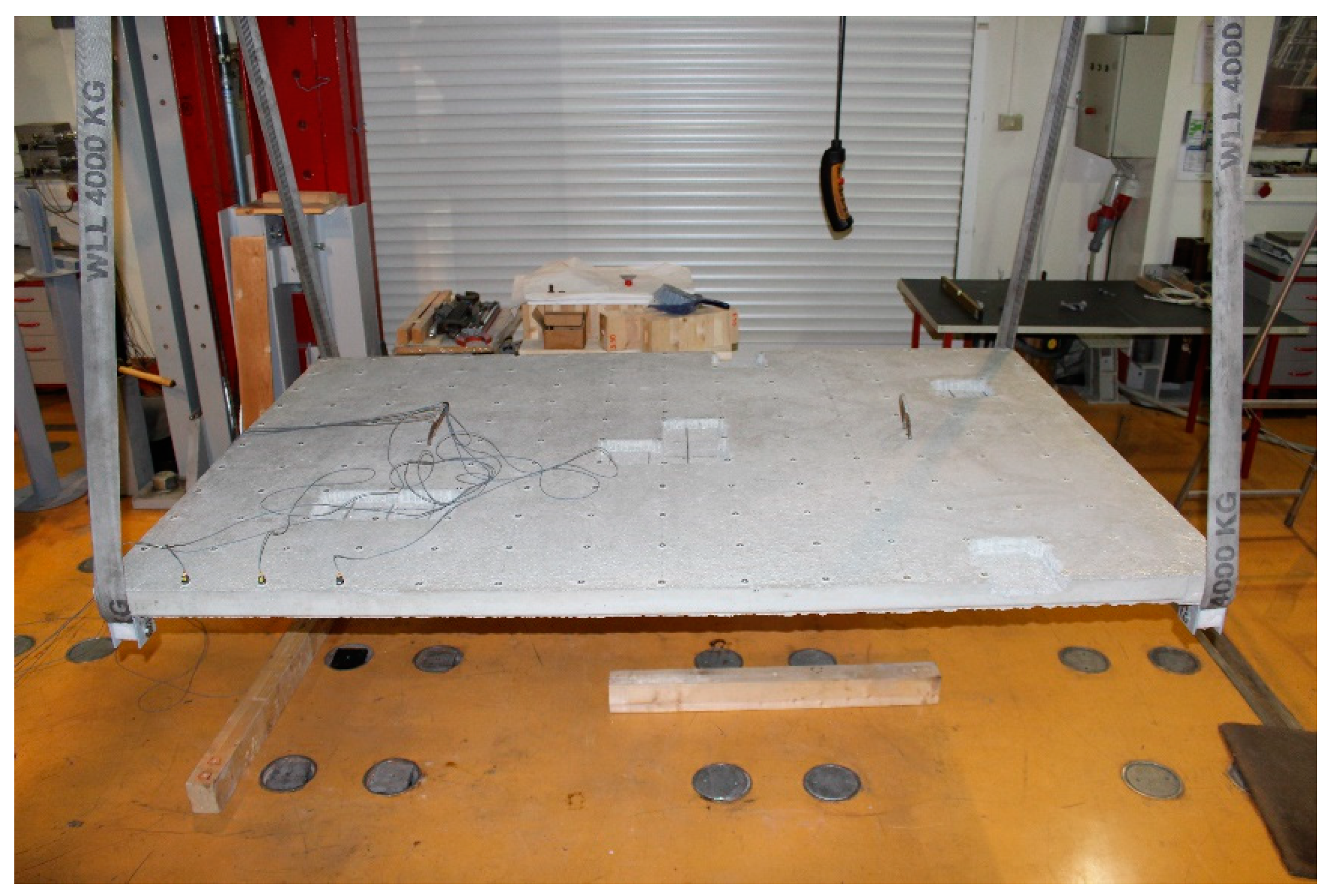
To achieve constant boundary conditions, we suspended the plate using very elastic ropes (Figure 2). The applied boundary conditions, a nearly ideal free-free set-up, were quickly implemented and easily repeated in the laboratory after each testing phase. The plate was tested in an undamaged state and then discrete damages were applied successively by removing parts of the surface from the top of the concrete plate.
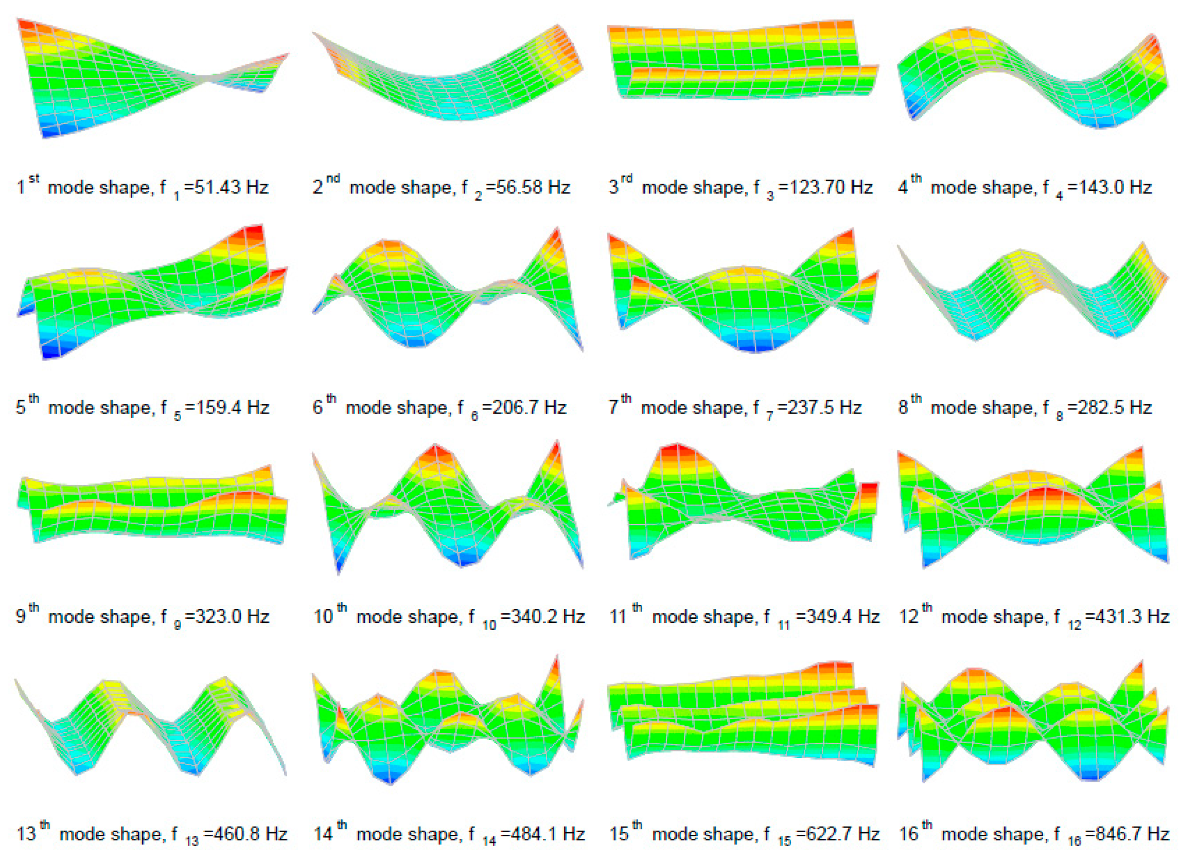
The plate was again tested after each successive damage simulation. A total of 16 experimentally obtained vertical mode shapes for the undamaged state (Figure 3) and each phase of the damaged state were observed in the analysis.

Simulation of Discrete Damages

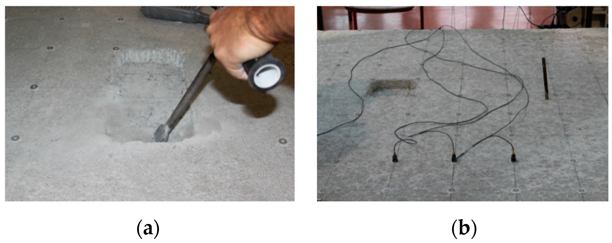
In the experimental research, discrete damage was applied by removing a part of the surface from the top of the concrete plate (Figure 4). The size of the discrete damaged rectangle was 15 × 16 cm, and the depth varied from 2 to 3 cm. The advantage of discrete damages lies in the fact that the damage location and the change in stiffness are precisely defined. Furthermore, it is possible to simulate a full range of damages, and the MSDI method can be tested using more than one damage location. In sequence, a total of 10 discrete damage cases were simulated on the concrete plate. It is known from the literature that stiffness has a dominant influence on the changes in mode shapes [38]. Therefore, the loss of mass was neglected in the experimental part of this research. Furthermore, the method was previously validated on numerical models [30,31] based only on the reduction of stiffness without including the effect of changes in mass.
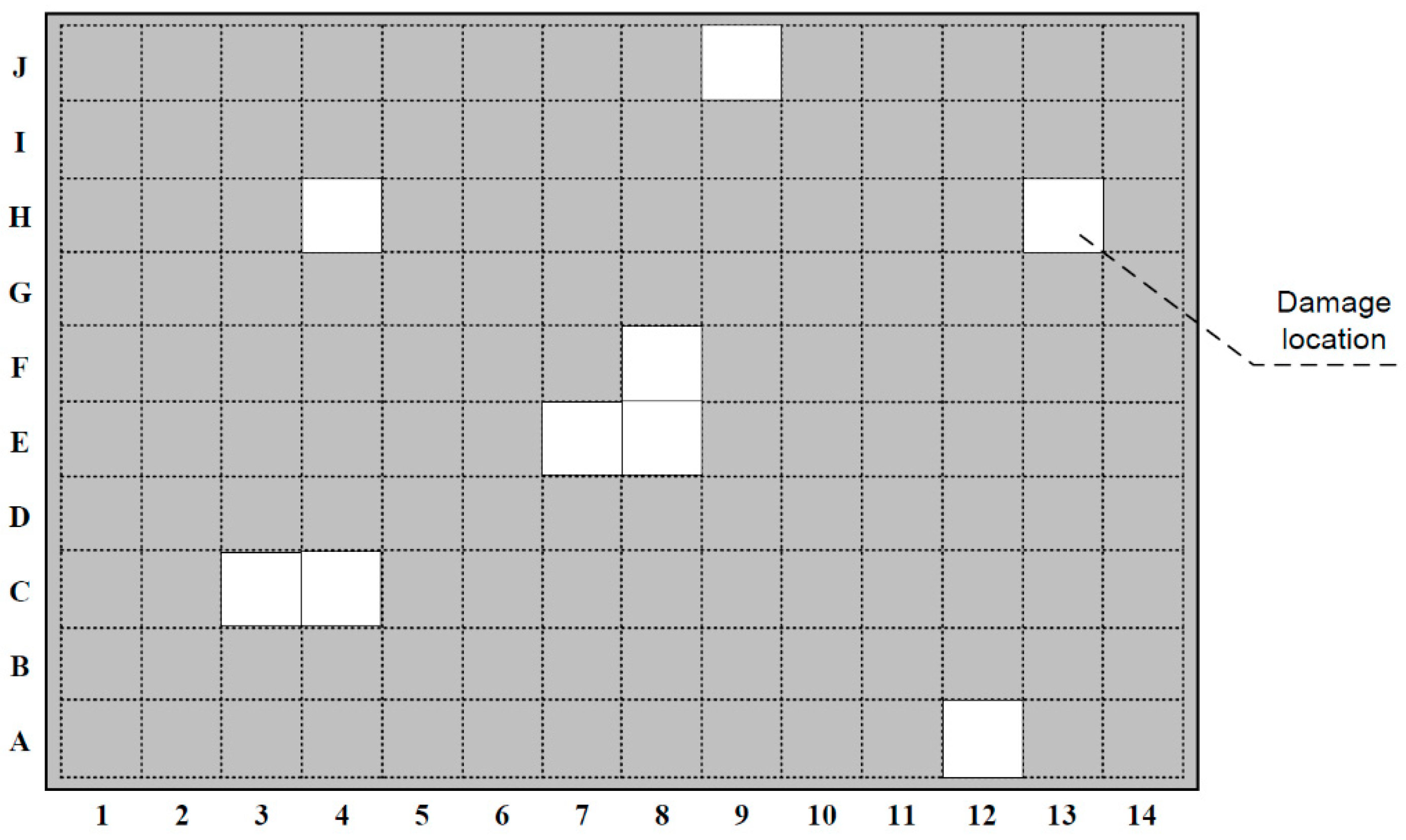
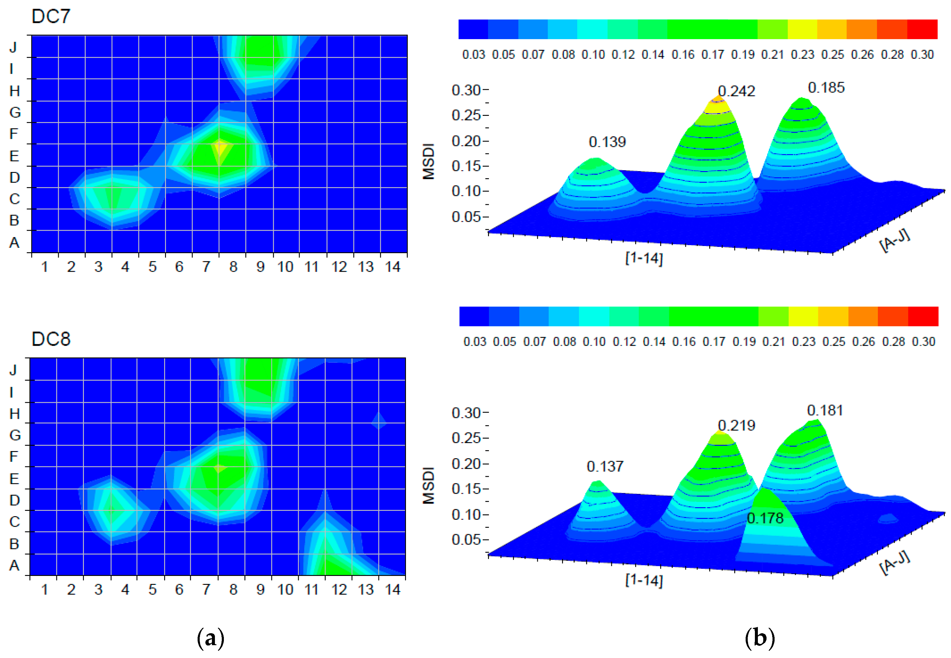
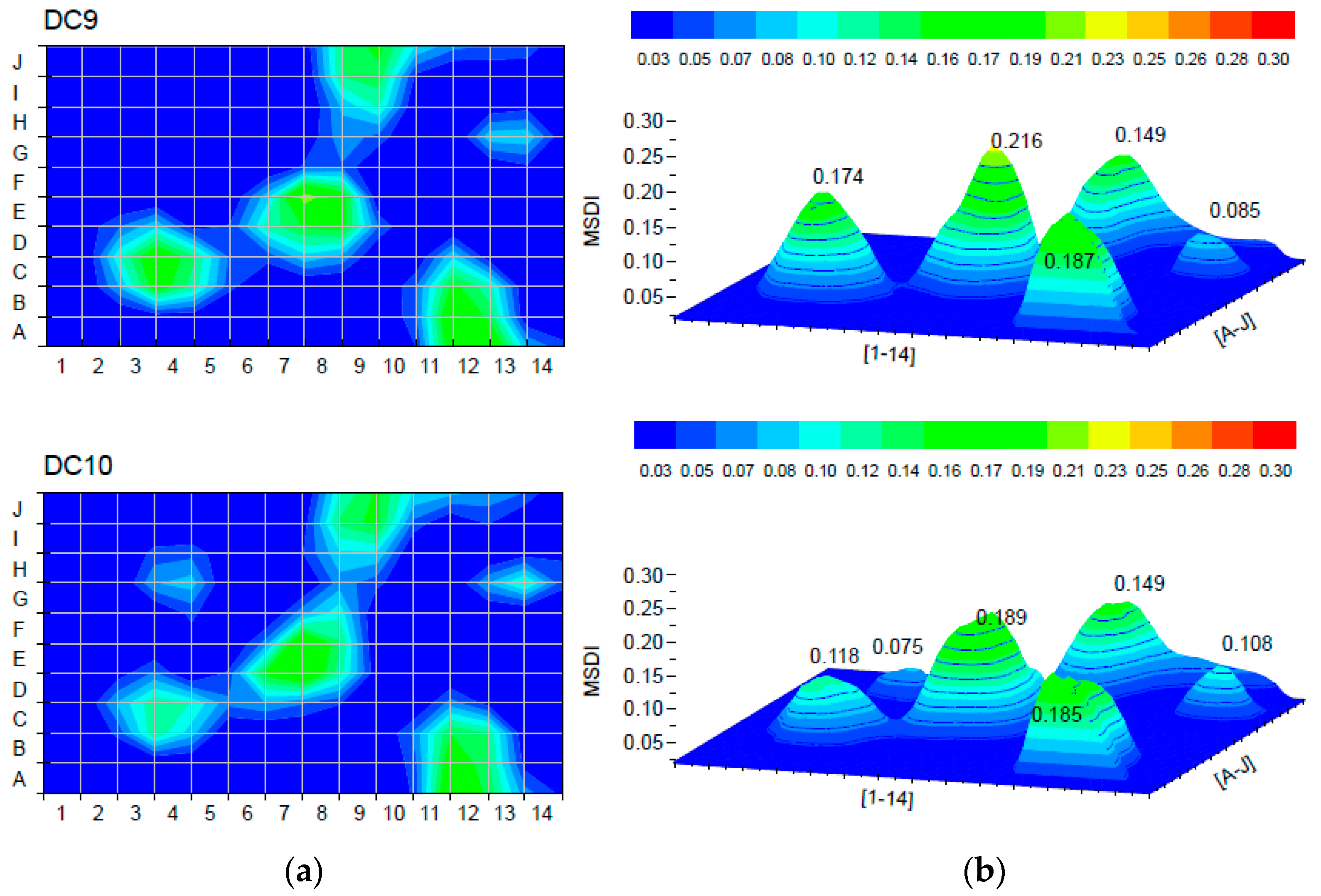
The first discrete damage was applied at the element E8 (damage case DC1) by reducing the concrete thickness for 2 cm. Afterward, an additional 1 cm of concrete was removed (damage case DC2). The remaining discrete damages were simulated by removing 3 cm of concrete at the plate elements as follows: F8, E7, C4, C3, J9, A12, H13, and H4. Locations of all discrete damages are presented in Figure 5. Different damage cases are listed in Table 1.

3. Results and Discussion

On the basis of experimental research, we performed a sensitivity analysis of the MSDI method, considering the effect of the damage level, the effect of the damage zone size, and ultimately the effect of multiple damages.

3.1. Effect of Damage Level at a Single Damage Location

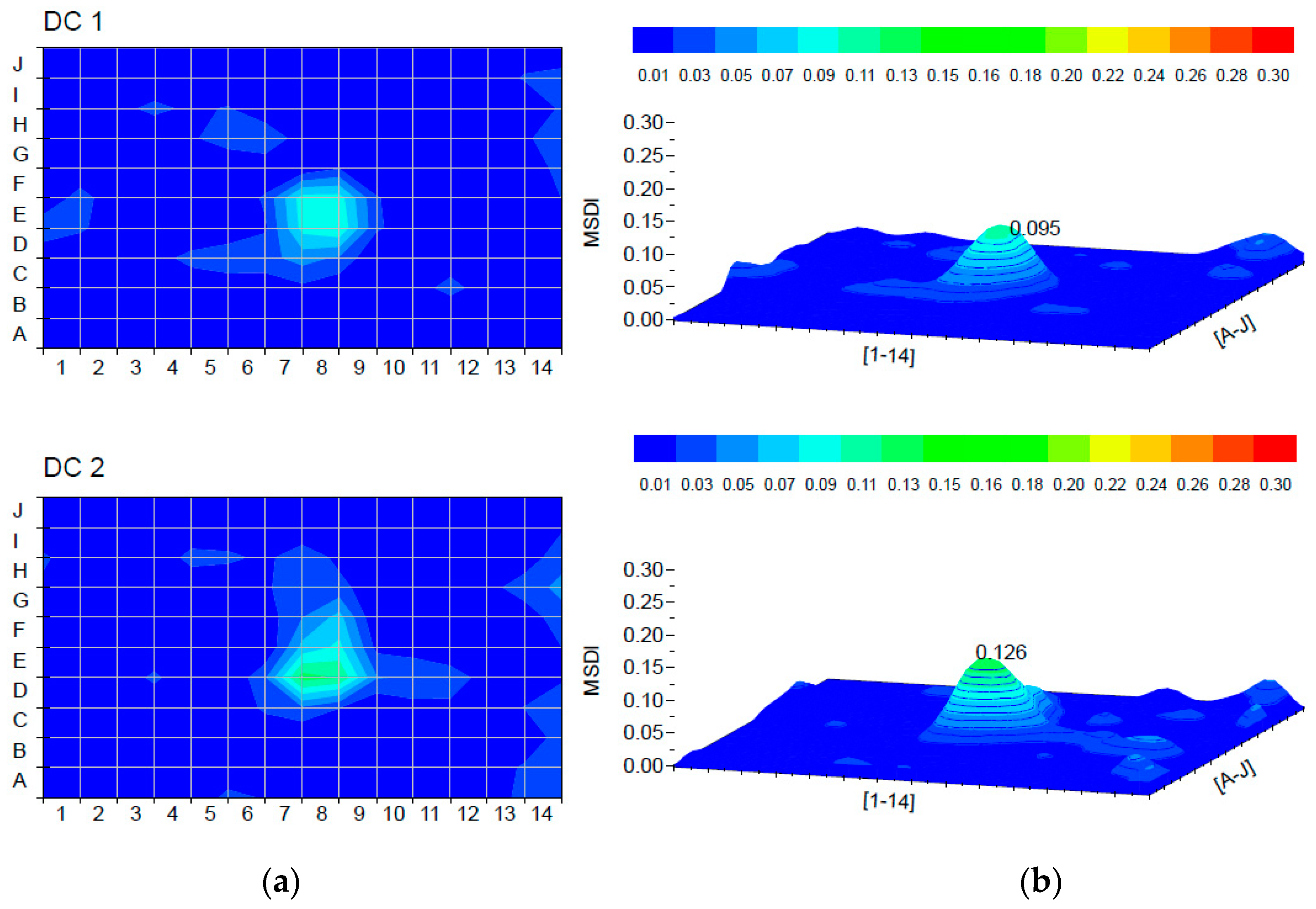
The first two damage cases at a single damage location were analyzed to determine the effect of the damage level when using the MSDI method. Damage cases DC1 and DC2 at element E8 simulated two levels of damage, “small” (depth of 2 cm) and “moderate” damage (depth of 3 cm). The damage location was determined by the MSDI method and presented as a colored graphical representation in Figure 6 for the first two damage cases. The MSDI values were calculated according to Equation (4). The peak values indicate the location of the damage on the plate in 3D view, and the damaged area is presented in 2D view. The exact location of the discrete damage, the element E8, was accurately identified. Moreover, the increase from small to moderate damage was followed by the increase of the MSDI value.
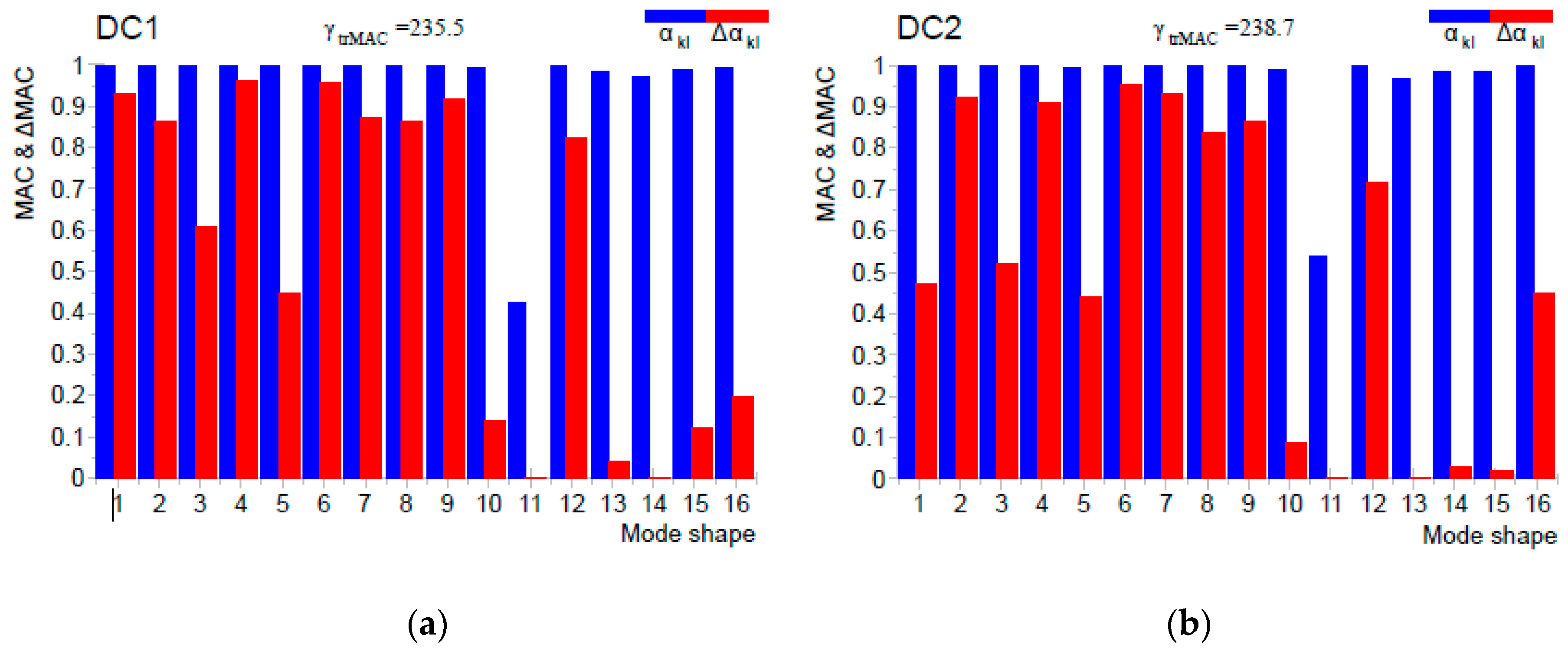
Furthermore, it is interesting to compare diagonal elements of the MAC and ΔMAC matrices both in numerical and experimental examples. In the numerical analysis, almost all coefficients participate with the maximum value 1 when damage is detected [30] because there are no measurement uncertainties. The comparison of experimentally obtained values is presented in Figure 7 for the first 16 mode shapes of the plate for damage cases DC1 and DC2. Some of the mode shapes for both damage cases were inconsistent (Figure 7a, mode shapes 11, 13, 14; Figure 7b, mode shapes 11, 13, 14, 15) in the undamaged and damaged states as a result of noise in the measurement signal and some other uncertainties (experimentally unrepeatable boundary conditions). It is shown that only a few mode shapes participated with values close to 1 (Figure 7a, mode shapes 1, 4, 6), whose weighting factor Δ α k l on modal displacements (Equations (5) and (6)) was sufficient for damage localization. Mentioned uncertainties are challenging to simulate or predict by numerical analysis. Thus, it is essential to emphasize the importance of validating damage detection methods on the basis of experimental results.

3.2. Effect of Damage Zone Size

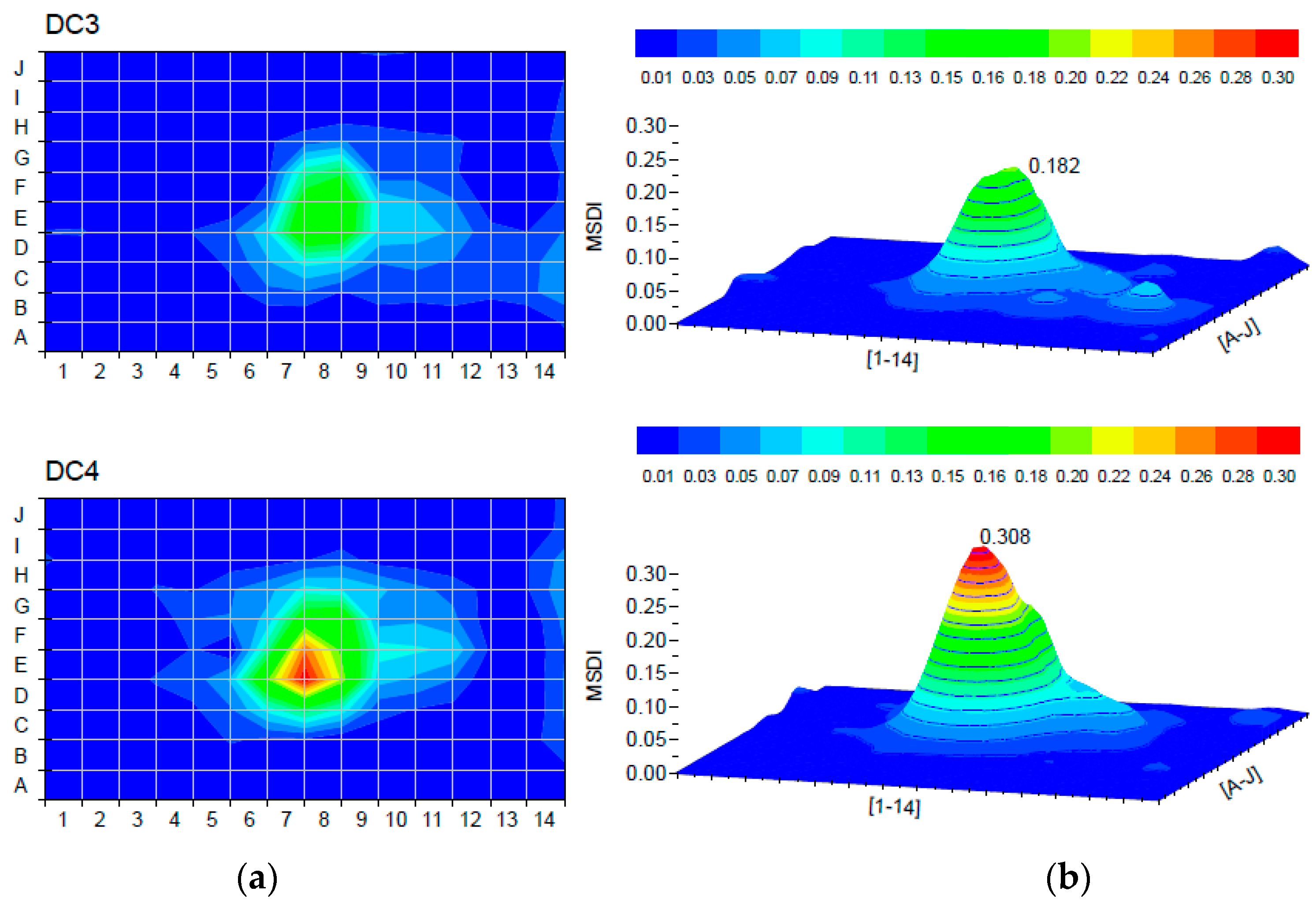
In this section, the influence of the damage zone size on the sensitivity of the MSDI method was considered. The third level of damage can be described as “large” damage, simulated by the loss of depth which is equal to “moderate” damage (3 cm) but with more than one damaged element. These substantial damages were simulated as damage cases DC3 (elements E8 and F8) and DC4 (elements E8, F8, and E7). Figure 8 summarizes the results of the effect of the damage zone size. In both damage cases, the damage was accurately localized. Moreover, the method can be used to determine larger damaged zones, i.e., several adjacent damaged elements. The MSDI values kept increasing with the addition of more damage.

3.3. Effect of Multiple Damages

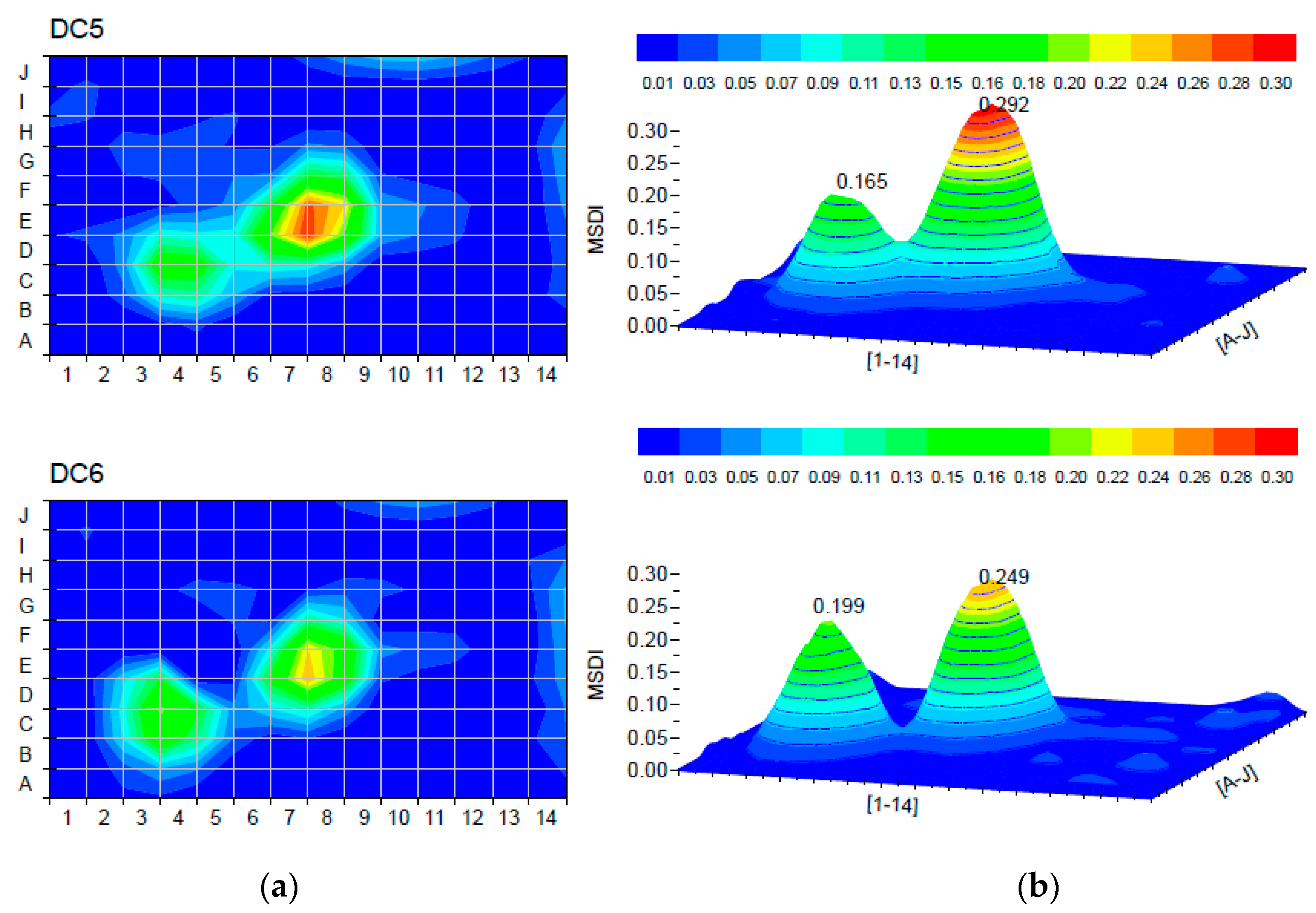
The remaining damage cases were analyzed to primarily investigate the effect of multiple damages on the MSDI method. In damage cases DC5 (DC4 + element C4) and DC6 (DC5 + element C3), the effect of multiple damages and the effect of the damage zone size were considered by adding another damage location on the plate. When we compared the results for both damage cases in Figure 9, we found that the MSDI method was able to register both damages, regardless of the damage zone size. The peak MSDI values at the two locations coincided with the reduction of stiffness. Moreover, the damage severity was smaller at the single damaged element C4 (see Figure 9, DC5) than the damaged zone C4-C3 (see Figure 9, DC6).
The following two multiple damage cases DC7 and DC8 included damaged elements at the free edges of the plate. The results shown in Figure 10 indicate that the method effectively identified multiple damages regardless of the location of the damaged zone. Nevertheless, as previously concluded in the finite element analysis [30], the damage severity was influenced by the damage location. Therefore, the severity of multiple damages cannot be determined by using this method.
The last two damage cases DC9 and DC10 considered two additional random single damage locations in elements H13 and H4. The results of simulated damages are shown in Figure 11, and it can be found that all simulated damages were accurately localized by the proposed algorithm regardless of the damaged zone size or the damage location.
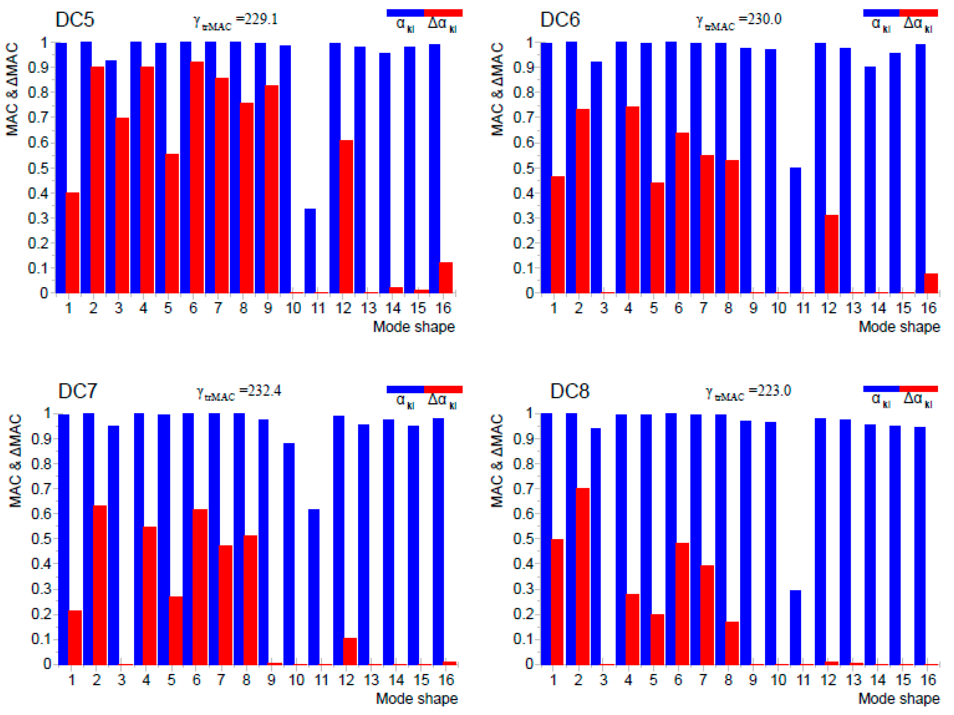
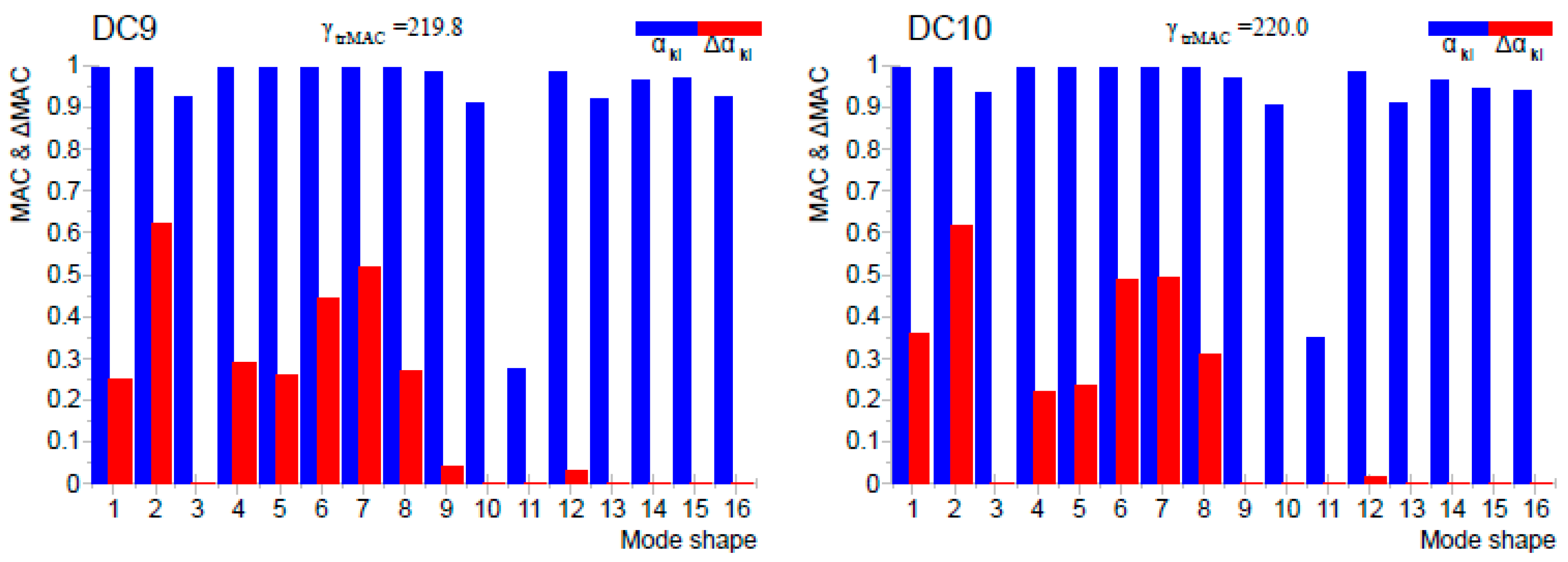
The diagonal elements of the MAC and ΔMAC matrices are shown for the damage cases DC5 to DC10 in Figure 12. It is noted that the number of mode shapes that were participating in damage detection decreased with the introduction of new damages. The first reason was that the intensity ( α k l value) decreased due to the low degree of consistency between estimated modal vectors in the undamaged and damaged states. The second reason was that some mode shapes entirely disappeared due to a significant change of consistency between estimated modal vectors. Even though a smaller number of mode shapes were used for damage detection based on the MSDI method, they were still able to provide useful information about the location of structural damage.
The accuracy of the MSDI method for damage localization depends on the number of measurement points (degrees of freedom) for some element or structure. In order to apply this method in practice within the structural health monitoring system (e.g., bridges, tall buildings), one must optimize the number of measuring points.
To obtain better reliability of the damage detection by using the presented method, we recommend as many experimentally obtained mode shapes as possible. In the paper, all experimentally observed mode shapes are presented and were used in the MSDI method, although a large number of mode shapes (for instance, Figure 12, DC 9) did not participate at all in damage detection or participate with significantly reduced impact.
The environmental (e.g., temperature) and serviceability effects were not considered in this research. It is necessary to consider the effects of temperature changes depending on the boundary conditions of the structure. Under the influence of different temperatures, the mode shapes can be changed significantly, and this can affect the MSDI analysis.

4. Conclusions

In this study, experimental validation of the mode shape damage index (MSDI) method for damage detection was performed on a reinforced concrete plate. Ten discrete damage cases were simulated by removing a part of the top layer on the concrete plate. On the basis of the measurement of the vibration response, we determined the dynamic properties of the plate in the undamaged and damaged conditions by applying the operational modal analysis. This method is particularly challenging due to many factors that can affect the accuracy of measurement and, therefore, can directly affect the damage analysis results. Namely, damage-induced changes in mode shapes are minimal, and every error in the experimental analysis of mode shapes can significantly affect the accuracy of damage detection. By applying the MSDI method on the experimental model, it is evident that the mode shapes that did not match for any reason were excluded from the damage analysis. Even though a smaller number of mode shapes were used for damage detection in the MSDI method, they can still provide useful information about the location of structural damage.
The conclusions from previous numerical research are confirmed. The MSDI method can be used to detect the existence of damage, identify single and/or multiple damage locations, and distinguish damages with different levels of severity. It must be emphasized that the severity of damage detected with this method depends on boundary conditions and the location of the damage.
The MSDI method can easily be implemented in the vibration-based damage detection system. This method does not require the numerical model for the damage assessment, and the measurement is simplified due to the fact it uses only the ambient response of the structure for the estimation of modal parameters. It is also possible to combine this method with some of the existing methods. For example, the change in natural frequency of structure can serve as an indicator of the damage existence, and then by applying the MSDI method, the damage location can be determined.
Although this method shows promising results and successful validation through experimental tests, there are still many challenges for future research in structural damage identification. By applying the MSDI method, it is still not possible to determine damage severity. Hence, future research is recommended in that direction. Furthermore, various uncertainties that may affect the results by using this method need to be considered, for instance, inconsistent boundary conditions, various ambient conditions (e.g., temperature, humidity), various types of damages (e.g., bending cracks, corrosion, wear), and serviceability effects (traffic) in a laboratory environment and in real structures.

Author Contributions

All authors have contributed to the contents within this paper. Conceptualization, I.D.; methodology, I.D.; experimental research, I.D., software, D.D. and M.B.; validation, I.D. and A.S.; literature review, I.D. and A.S.; writing—original draft preparation, I.D.; writing—review and editing, A.S.; visualization, D.D. and M.B.; supervision, D.D. All authors have read and agreed to the published version of the manuscript.

Funding

This research received no external funding.

Institutional Review Board Statement

Not applicable.

Informed Consent Statement

Not applicable.

Conflicts of Interest

The authors declare no conflict of interest.

References

  1. Cornwell, P.; Farrar, C.R.; Doebling, S.W.; Sohn, H. Environmental Variability of Modal Properties. Exp. Tech. 1999, 23, 45–48. [Google Scholar] [CrossRef]
  2. Wang, F.L.; Chan, T.H.T. Review of Vibration-Based Damage Detection and Condition Assessment of Bridge Structures Using Structural Health Monitoring. In The Second Infrastructure Theme Postgraduate Conference: Rethinking Sustainable Development: Planning, Engineering, Design and Managing Urban Infrastructure; Queensland University of Technology: Brisbane, Australia, 2009; pp. 35–47. [Google Scholar]
  3. Rytter, A. Vibrational Based Inspection of Civil Engineering Structures. Ph.D. Thesis, Department of Building Technology and Structural Engineering, Aalborg University, Aalborg, Denmark, 1993. [Google Scholar]
  4. Salawu, O.S. Detection of Structural Damage through Changes in Frequency: A Review. Eng. Struct. 1997, 19, 718–723. [Google Scholar] [CrossRef]
  5. Messina, A.; Williams, E.J.; Contursi, T. Structural Damage Detection by a Sensitivity and Statistical-Based Method. J. Sound Vib. 1998, 216, 791–808. [Google Scholar] [CrossRef]
  6. Morassi, A. Identification of a Crack in a Rod Based on Changes in a Pair of Natural Frequencies. J. Sound Vib. 2001, 242, 577–596. [Google Scholar] [CrossRef]
  7. Kim, J.T.; Stubbs, N. Crack Detection in Beam-Type Structures Using Frequency Data. J. Sound Vib. 2003, 259, 145–160. [Google Scholar] [CrossRef]
  8. Salehi, M.; Ziaei-Rad, S.; Ghayour, M.; Vaziri-Zanjani, M.A. A Structural Damage Detection Technique Based on Measured Frequency Response Functions. Contemp. Eng. Sci. 2010, 3, 215–226. [Google Scholar]
  9. Yang, Z.; Chen, X.; Yu, J.; Liu, R.; Liu, Z.; He, Z. A Damage Identification Approach for Plate Structures Based on Frequency Measurements. Nondestruct. Test. Eval. 2013, 28, 321–341. [Google Scholar] [CrossRef]
  10. Beskhyroun, S.; Wegner, L.D.; Sparling, B.F. New Methodology for the Application of Vibration-Based Damage Detection Techniques. Struct. Control Health Monit. 2012, 19, 632–649. [Google Scholar] [CrossRef]
  11. Xu, Y.; Zhu, W. Non-Model-Based Damage Identification of Plates Using Measured Mode Shapes. Struct. Health Monit. 2017, 16, 3–23. [Google Scholar] [CrossRef]
  12. Pandey, A.K.; Biswas, M. Experimental Verification of Flexibility Difference Method for Locating Damage in Structures. J. Sound Vib. 1995, 184, 311–328. [Google Scholar] [CrossRef]
  13. Catbas, F.N.; Brown, D.L.; Aktan, A.E. Use of Modal Flexibility for Damage Detection and Condition Assessment: Case Studies and Demonstrations on Large Structures. J. Struct. Eng. 2006, 132, 1699–1712. [Google Scholar] [CrossRef]
  14. Abdel Wahab, M.M.; De Roeck, G. Damage Detection in Bridges Using Modal Curvatures: Application to a Real Damage Scenario. J. Sound Vib. 1999, 226, 217–235. [Google Scholar] [CrossRef]
  15. Maeck, J.; De Roeck, G. Damage Detection on a Prestressed Concrete Bridge and RC Beams Using Dynamic System Identification. Key Eng. Mater. 1999, 167, 320–327. [Google Scholar] [CrossRef]
  16. Shi, Z.Y.; Law, S.S.; Zhang, L.M. Structural Damage Detection from Modal Strain Energy Change. J. Eng. Mech. 2000, 126, 1216–1223. [Google Scholar] [CrossRef]
  17. Hu, H.; Wang, B.T.; Lee, C.H.; Su, J.S. Damage Detection of Surface Cracks in Composite Laminates Using Modal Analysis and Strain Energy Method. Compos. Struct. 2006, 74, 399–405. [Google Scholar] [CrossRef]
  18. Meruane, V.; Lasen, M.; Droguett, E.L.; Ortiz-Bernardin, A. Modal Strain Energy-Based Debonding Assessment of Sandwich Panels Using a Linear Approximation with Maximum Entropy. Entropy 2017, 19, 619. [Google Scholar] [CrossRef] [Green Version]
  19. Fan, W.; Qiao, P. Vibration-Based Damage Identification Methods: A Review and Comparative Study. Struct. Health Monit. 2011, 10, 83–111. [Google Scholar] [CrossRef]
  20. Siow, P.Y.; Ong, Z.C.; Khoo, S.Y.; Lim, K.S. Damage Sensitive PCA-FRF Feature in Unsupervised Machine Learning for Damage Detection of Plate-Like Structures. Int. J. Struct. Stab. Dyn. 2021, 21. [Google Scholar] [CrossRef]
  21. Zhao, M.; Zhou, W.; Huang, Y.; Li, H. Sparse Bayesian Learning Approach for Propagation Distance Recognition and Damage Localization in Plate-like Structures Using Guided Waves. Struct. Health Monit. 2021, 20, 3–24. [Google Scholar] [CrossRef]
  22. Kahya, V.; Karaca, S.; Okur, F.Y.; Altunışık, A.C.; Aslan, M. Damage Localization in Laminated Composite Beams with Multiple Edge Cracks Based on Vibration Measurements. Iran. J. Sci. Technol. Trans. Civ. Eng. 2020, 45, 75–87. [Google Scholar] [CrossRef]
  23. Limongelli, M.P. The Surface Interpolation Method for Damage Localization in Plates. Mech. Syst. Signal Process. 2019, 118, 171–194. [Google Scholar] [CrossRef] [Green Version]
  24. Catbas, F.N.; Gul, M.; Burkett, J.L. Conceptual Damage-Sensitive Features for Structural Health Monitoring: Laboratory and Field Demonstrations. Mech. Syst. Signal Process. 2008, 22, 1650–1669. [Google Scholar] [CrossRef]
  25. West, M.; West, W. Illustration of the Use of Modal Assurance Criterion to Detect Structural Changes in an Orbiter Test Specimen. Proc. Air Conf. Aircr. Struct. Integr. 1984, 1, 1–6. [Google Scholar]
  26. Doebling, S.W.; Farrar, C.R.; Prime, M.B. A Summary Review of Vibration-Based Damage Identification Methods. Shock Vib. Dig. 1998, 30, 91–105. [Google Scholar] [CrossRef] [Green Version]
  27. Allemang, R.J. The Modal Assurance Criterion—Twenty Years of Use and Abuse. In Proceedings of the IMAC-XX: Conference & Exposition on Structural Dynamics, Los Angeles, CA, USA, 4–7 February 2002; p. 9. [Google Scholar]
  28. Pastor, M.; Binda, M.; Harčarik, T. Modal Assurance Criterion. In Procedia Engineering; Elsevier: Amsterdam, The Netherlands, 2012; Volume 48, pp. 543–548. [Google Scholar] [CrossRef]
  29. Tatar, A.; Niousha, A.; Rofooei, F.R. Damage Detection in Existing Reinforced Concrete Building Using Forced Vibration Test Based on Mode Shape Data. J. Civ. Struct. Health Monit. 2017, 7, 123–135. [Google Scholar] [CrossRef]
  30. Duvnjak, I.; Rak, M.; Damjanović, D. A New Method for Structural Damage Detection and Localization Based on Modal Shapes. In Proceedings of the Fifth International Symposium on Life-Cycle Civil Engineering (IALCCE 2016), Delft, The Netherlands, 16–19 October 2016. [Google Scholar]
  31. Duvnjak, I.; Damjanović, D.; Sabourova, N.; Grip, N.; Ohlsson, U.; Elfgren, L.; Tu, Y. Damage Detection in Structures—Examples. In Proceedings of the IABSE Symposium 2019 Guimarães: Towards a Resilient Built Environment—Risk and Asset Management, Guimarães, Portugal, 27–29 March 2019. [Google Scholar]
  32. Sun, L.; Shang, Z.; Xia, Y.; Bhowmick, S.; Nagarajaiah, S. Review of Bridge Structural Health Monitoring Aided by Big Data and Artificial Intelligence: From Condition Assessment to Damage Detection. J. Struct. Eng. 2020, 146, 04020073. [Google Scholar] [CrossRef]
  33. Hsieh, Y.-A.; Tsai, Y.J. Machine Learning for Crack Detection: Review and Model Performance Comparison. J. Comput. Civ. Eng. 2020, 34, 04020038. [Google Scholar] [CrossRef]
  34. Dang, H.V.; Raza, M.; Nguyen, T.V.; Bui-Tien, T.; Nguyen, H.X. Deep Learning-Based Detection of Structural Damage Using Time-Series Data. Struct. Infrastruct. Eng. 2020. [Google Scholar] [CrossRef]
  35. Zhang, L.; Brincker, R.; Andersen, P. An Overview of Operational Modal Analysis: Major Development and Issues. In Proceedings of the 1st International Operational Modal Analysis Conference (IOMAC 2005), Copenhagen, Denmark, 26–27 April 2005; pp. 149–160. [Google Scholar]
  36. Brincker, R.; Zhang, L.; Andersen, P. Modal Identification of Output-Only Systems Using Frequency Domain Decomposition. Smart Mater. Struct. 2001, 10, 441–445. [Google Scholar] [CrossRef] [Green Version]
  37. Gade, S.; Møller, N.B.; Herlufsen, H.; Konstantin-Hansen, H. Frequency Domain Techniques for Operational Modal Analysis. In Proceedings of the 1st International Operational Modal Analysis Conference (IOMAC 2005), Copenhagen, Denmark, 26–27 April 2005; p. 231. [Google Scholar]
  38. Khatibi, M.M.; Ashory, M.R.; Malekjafarian, A.; Brincker, R. Mass-Stiffness Change Method for Scaling of Operational Mode Shapes. Mech. Syst. Signal Process. 2012, 26, 34–59. [Google Scholar] [CrossRef]
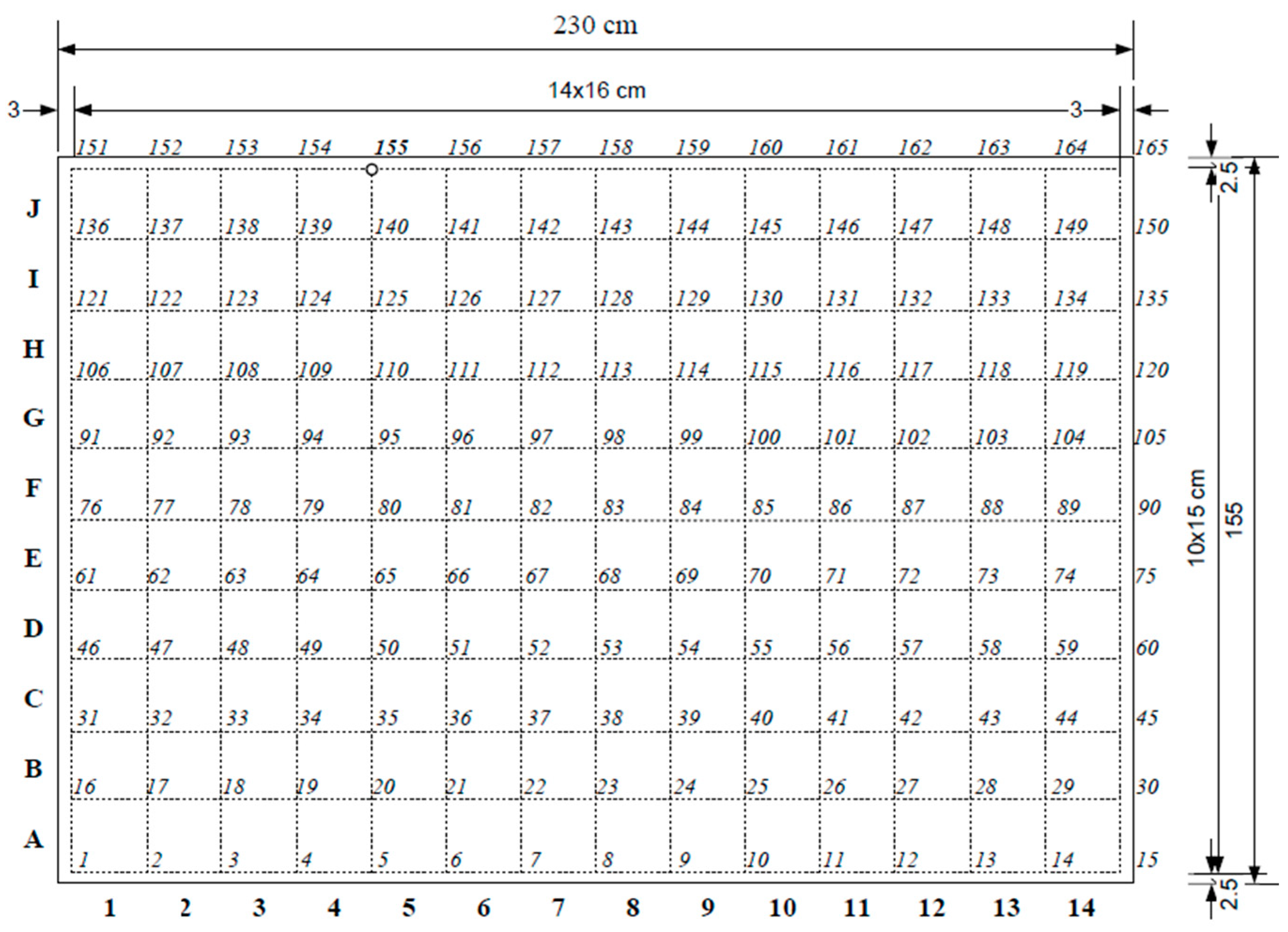
Figure 1. Measurement points on the RC plate.
Applsci 11 04589 g001
Figure 2. Suspended plate with discrete damages.
Applsci 11 04589 g002
Figure 3. Sixteen mode shapes obtained experimentally on the undamaged plate.
Applsci 11 04589 g003
Figure 4. Discrete damages on the RC plate: (a) chiseling; (b) one of the damage locations on the concrete plate.
Applsci 11 04589 g004
Figure 5. Discrete damage locations on the concrete plate.
Applsci 11 04589 g005
Figure 6. Damage localization for damage cases DC1 and DC2: (a) 2D; (b) peak values in 3D.
Applsci 11 04589 g006
Figure 7. Diagonal elements of the MAC and ΔMAC matrices: (a) damage case DC1; (b) damage case DC2.
Applsci 11 04589 g007
Figure 8. Damage localization for damage cases DC3 and DC4: (a) 2D; (b) peak values in 3D.
Applsci 11 04589 g008
Figure 9. Damage localization for damage cases DC5 and DC6: (a) 2D; (b) peak values in 3D.
Applsci 11 04589 g009
Figure 10. Damage localization for damage cases DC7 and DC8: (a) 2D; (b) peak values in 3D.
Applsci 11 04589 g010
Figure 11. Damage localization for damage cases DC9 and DC10: (a) 2D; (b) peak values in 3D.
Applsci 11 04589 g011
Figure 12. Diagonal elements of the MAC and ΔMAC matrices for damage cases DC5–DC10.
Applsci 11 04589 g012aApplsci 11 04589 g012b
Table 1. Damage cases simulated on the concrete plate.
Damage CaseElementsDepth (cm)
DC1E82
DC2E83
DC3E8 + F83
DC4DC3 + E73
DC5DC4 + C43
DC6DC5 + C33
DC7DC6 + J93
DC8DC7 + A123
DC9DC8 + H133
DC10DC9 + H43
Publisher’s Note: MDPI stays neutral with regard to jurisdictional claims in published maps and institutional affiliations.