Abstract
In heterogeneous microfluidic immunosensors, the diffusion boundary layer produced on the sensing area represents a critical factor that limits the biosensor performance. A three-dimensional simulation using the finite element method on the binding reaction kinetics of C-reactive protein (CRP) has been performed. We present a new microfluidic biosensor based on a novel reaction-surface design without and with electrothermal force. Two reaction surface configurations were studied. The kinetic reaction rate was calculated with coupled Navier−Stokes, mass diffusion, energy, and Laplace equations. The numerical results reveal that the characteristics of a microfluidic biosensor are more enhanced by using the circular ring design of the sensing area coupled with the electrothermal force. The rate of initial slope related to the association phase is multiplied by a factor 2 when the voltage is increased from 10 to 15 V. The results prove to be valuable in designing new microfluidic biosensors.
1. Introduction
During the last decade, the development of nanofluidic devices has grown considerably owing to their ability to control small amounts of fluid. Their unique characteristics have attracted researchers’ interest in several fields such as chemical, biological, and biomedical applications [,,,]. In the biomedical field, many biochemical processes such as mixing [] and sensing [,] can be manufactured and integrated in a single chip. Microfluidic biosensors offer several advantages such as reduced consumption of the reagents, short analysis time, and simultaneous detection of multiple analytes []. Immunosensors represent a class of biosensors using the sensitivity of antibody-antigen interactions for the detection of appropriate analytes. This technique is used to quantify the proteins and biological small molecules. Two types of immunoassays have been found: homogeneous immunoassay, where the interaction between antibodies and antigens is made in solution, and heterogeneous immunoassays where the interaction is made between antibodies immobilized on a solid membrane and the antigen present at the boundary layer []. In heterogeneous immunoassays, the concentration of the binding complex of antigen–antibody on the reaction surface has a crucial role. The chemical reaction time scale and the transport phenomena rate by diffusion and convection occurring in a heterogeneous immunosensors are related by the Damköhler number (Da). When Da is higher, mass transport is limited, while association kinetic is lower for low Da values []. For the microfluidic biosensors, the ratio of the diffusion velocity of molecules to the reaction surface is comparatively small. A diffusion boundary layer is developed and it leads to limiting the efficiency of biosensor [,]. Several methods have been tested to improve the phenomenon of transport of the analytes to the reaction surface such as microfluidic confinement [], and electrothermal effect [,,,].
In our previous studies, we proposed two methods to improve the reaction rate: one based on inserting a cylindrical obstacle within the microchannel near to the reaction surface and the other based on flow confinement [,,]. These studies are compared to the electrothermal flow and show its efficiencies. However, these numerical simulations have been done for two-dimensional configurations. This is somewhat constraining for spatial factors and practical design, especially the sensing area.
In the present work, three-dimensional simulations are performed. The effect of the sensing area shape and the geometrical location of the electrodes on the microfluidic biosensor performance are investigated.
2. Biosensor Geometry and Theory
2.1. Biosensor Design
The primary purpose of this work is to enhance the biosensor performance by proposing a new design of reaction surface and electrodes. This system consists of mixing a small concentration of analyte with the water in a microchannel having a biosensor on which antibody ligands are fixed. A binding reaction between the antibody fixed at the reaction surface and the antigen is developed.
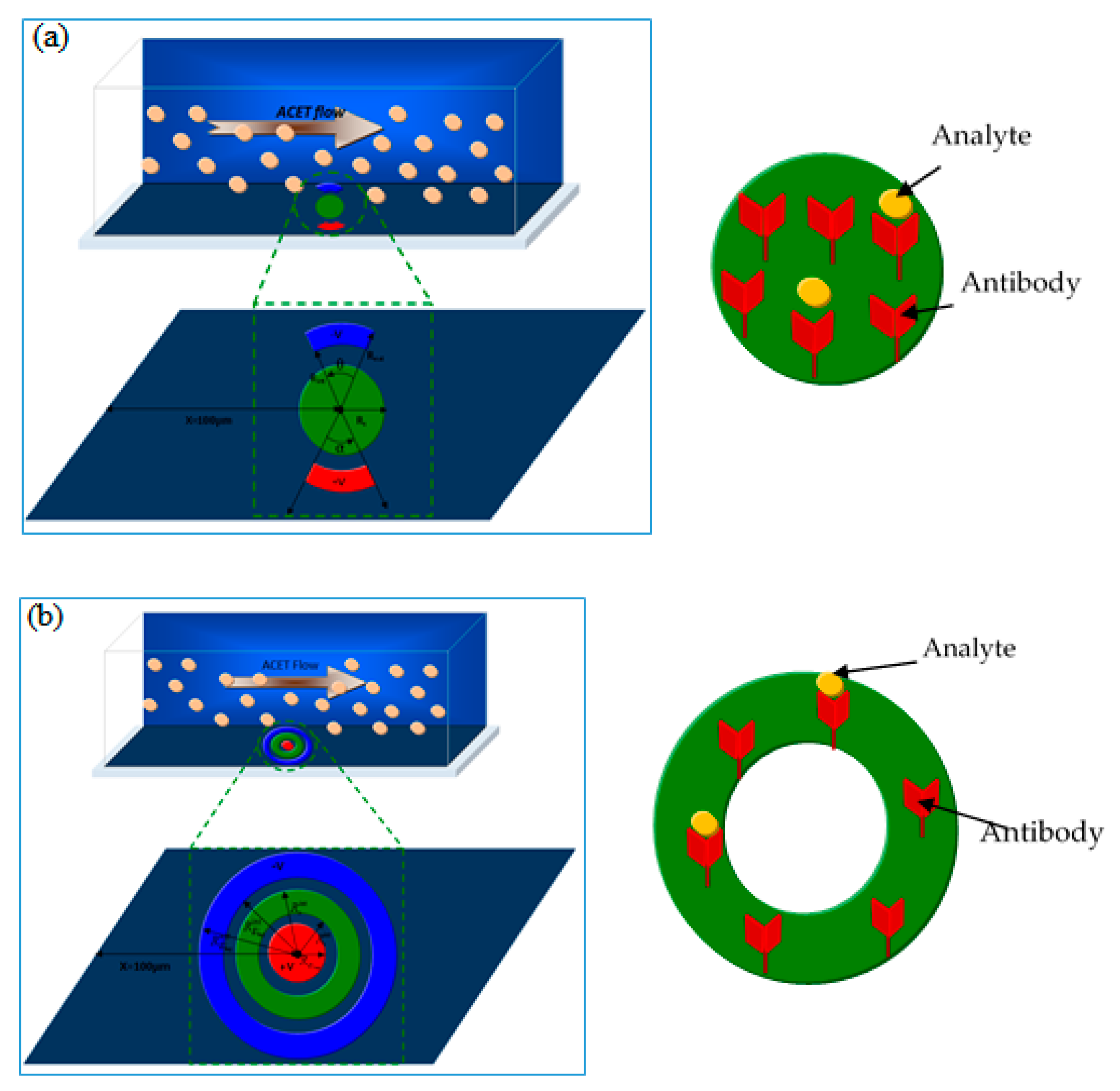
Figure 1 illustrates the three-dimensional schematic of microfluidic biosensors. The microchannel used in this study was 250 μm length, 50 μm wide and 40 μm high. The locations of reaction surface and electrode pair are shown in Figure 1. The geometric parameters of two biosensor models are given in Table 1 and Table 2, respectively.
Figure 1.
Sketch of two types of 3D models of a microfluidic biosensor. The channel dimensions (length, width, and height) are respectively 250 µm, 50 µm, and 40 µm. (a) Geometry 1; (b) Geometry 2.
Table 1.
Geometrical parameters for type 1 of the biosensor model.
Table 2.
Geometrical parameters for the second biosensor model.
Based on our previous studies [,,,,] and literature studies [], it appears that the formation of the diffusion boundary layer is closely related to the length of the reaction surface and the position of the electrodes. For this reason, the above configurations are proposed in order to improve the microfluidic biosensor response and reduce the diffusion boundary layer.
2.2. Governing Equations
The application of a non-uniform Alternating Current (AC) electric field on a fluid provokes inhomogeneities of the electrical permittivity ε and the conductivity σ of the solution due to the temperature gradient subsequent to the Joule effect. These inhomogeneities of ε and σ give rise to the electrothermal force given by this expression:
where represents the angular frequency of the electric field , is the electrical conductivity and is permittivity of the fluid. For aqueous media at 293 K, and [] where T is temperature of the fluid.
The electrothermal flow inside the microfluidic chips is assumed to be steady and laminar. The fluid is Newtonian. The flow is governed by the continuity, Navier-Stokes and the energy balance equations:
where , p, ρ, μ, k, and Cp are the velocity vector, pressure, density, dynamic viscosity, thermal conductivity, and specific heat of the fluid, respectively.
The transport of the antigen in bulk liquid phase from the left inlet is expressed by the Fick second law involving both conduction and convection:
Here, C is the bulk concentration (mol/m3), D is the diffusion coefficient of the antigen, and t is the time (s).
Equation (3) reveals clearly that the analyte concentration in the bulk is affected by the velocity field which is itself influenced by the electrothermal force described in Equation (1). Therefore, the concentration at the biosensor surface will be affected by this force.
The reaction between the antibody fixed at the reaction surface and the suspended target analyte (antigen) is modeled by the so-called first-order Langmuir adsorption equation. The binding reaction at the sensitive surface is symbolized according to:
where θ and Cs are the surface concentration (mol/m2) of the active sites and the antigen-antibody complexes, respectively. The rate constants related to adsorption and desorption are k1 and k2, respectively.
The rate equation governing the time evolution of antigen-antibody complexes Cs at the sensor surface is given by the following expression:
where θ0 denotes the total number of active sites accessible on the sensor surface.
In order to solve the above governing equations (Equations (1)–(4)), we used the boundary conditions presented in Table 3.
Table 3.
Boundary conditions used in this simulation.
In the above conditions (Table 3), different meanings may be assigned to the word insulation owing to the considered equation. In the matter of the boundary conditions related to the energy equation, this word means thermal insulation, that is, the conduction heat flux through the considered surface is equal to zero. Concerning the Poisson equation, electrical insulation is used at all the boundaries except the electrodes. In other words, at these boundaries, the electrical field is equal to zero to insure its continuity.
Concerning the analyte transport equation, the word impermeable means that there is no diffusion through the walls (except the reaction surface).
The numerical method used to discretize the above equations and perform the simulations is the finite element method.
Table 4 illustrates the values of the physicochemical parameters used for this numerical study. These values are taken from the literature [,,].
Table 4.
Numerical values of the parameters used in the current simulations [,,].
3. Results and Discussion
3.1. Model Validation
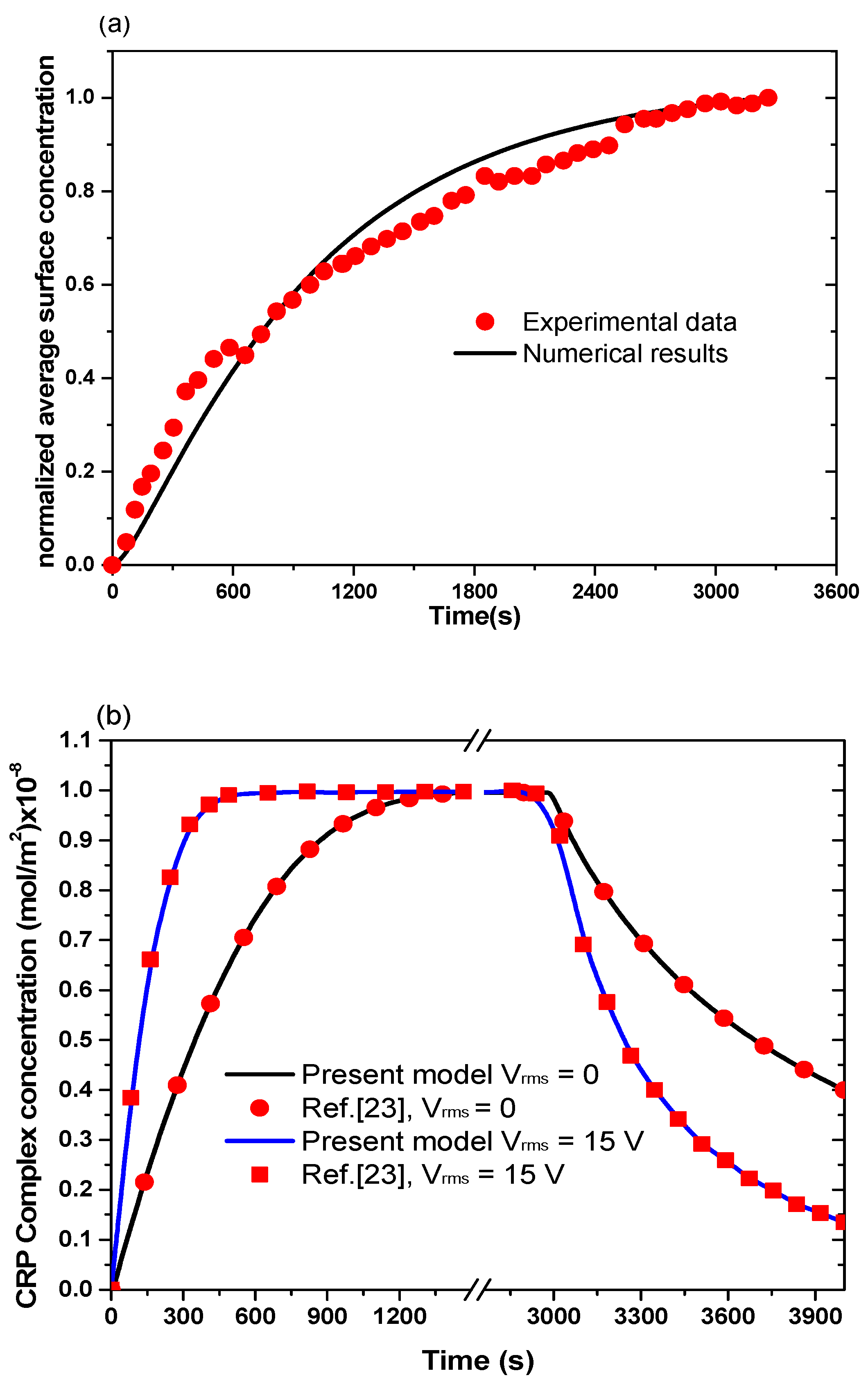
The chemical binding kinetics of the analyte (Anti-rabbit IgG) with the ligand (Rabbit IgG) at the reaction surface has been validated with experimental results of Hofmann et al. [] without confinement flow and for the case of no AC electric field. Figure 2a presents the transient evolution of the normalized concentration of the complex. We notice good agreement between the simulation results with the experimental data of Hofmann et al. [].
Figure 2.
Numerical results of C-reactive protein (CRP) complex concentration as a function of time (a) compared to experimental data from Hofmann et al. [] and (b) compared to results from Huang et al. [] with and without electrothermal force.
Figure 2b compares the results obtained by the present studies with those obtained by Huang et al. [] in the cases without and with the electrothermal force. A good agreement has been observed. It should be noted that several components of the computation code has also been validated in our previous papers [,,,,].
In order to optimize microfluidic biosensor performance, several parameters were tested in this work. Two biosensor geometries with two forms of reaction surface were studied.
3.2. Effect of Surface Reaction Shape
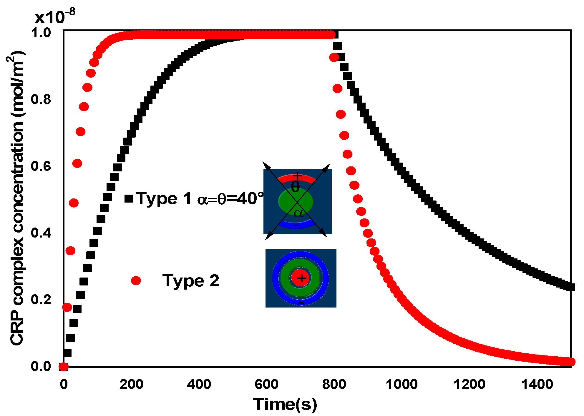
Figure 1 exhibits the geometry of the two biosensors having different shapes of reaction surface and electrode arrangement. Figure 3 and Figure 4 show the transient evolution of the CRP complex of these two biosensors for uave = 100 µm/s without applied voltage (Vrms = 0 V) and with applied voltage (Vrms = 15 V), respectively. The geometric parameters of the two biosensor models are given in Table 1 and Table 2.
Figure 3.
Temporal evolution of the average surface concentration of CRP complex for the two types of biosensors without applied voltage Vrms = 0 V. The first model of reaction surfaces is circular but the second model of reaction surface is a disk. The average inlet velocity is fixed at 100 µm/s.
Figure 4.
Temporal evolution of the average surface concentration of CRP complex for the two types of biosensors for Vrms = 15 V. For the first model, the electrodes angles (θ, α) are fixed to 40°. The average inlet velocity is fixed at 100 µm/s.
For the first model of the biosensor, the reaction surface was a disk of radius Rs = 15.96 μm while for the second model it was a circular ring of outer and inner radius = 25 µm and = 20 µm, respectively. In both models of biosensors, the area of the reaction surface was taken equal to S = 800 µm2. The electrodes angle θ and α for the first biosensor model were equal to 40°.
Figure 3 and Figure 4 present the evolution of the normalized complex concentration Cs during the association and dissociation phases. During the first phase (association), the complex concentration increases almost linearly until reaching saturation. At this stage (saturation), all the ligands are occupied by the analytes injected at the inlet of channel. After a given time ( = 800 s), the injection of analyte is stopped and therefore the kinetic bond dissociation will take place.
In the case of Vrms = 0 V (Figure 3), the binding reaction rate related to the circular reacting surface without the application of the electrothermal force was smaller than that related to the reaction surface having the form of a circular ring.
In the case of Vrms = 15 V (Figure 4), a significant improvement in the binding reaction was observed for the second model compared to the first model. The electrothermal force induced by the electrodes for the second model contributed effectively to the increase of the reaction rate. The shape of the reaction surface and the electrode arrangement have an important role in improving the biosensor response.
3.3. Effect of the Applied Voltage
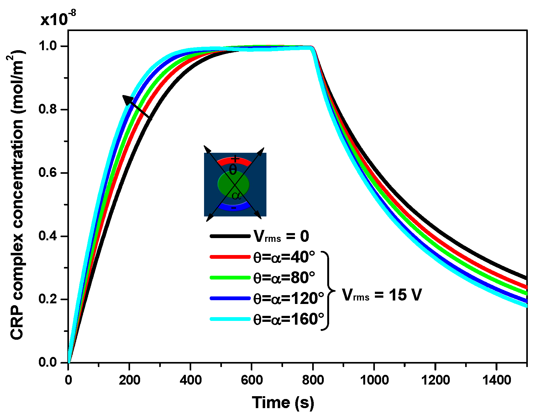
Figure 5 illustrates the effect of electrodes angles (θ, α) on the transient evolution of CRP complex concentration for Vrms = 15 V and uave = 100 µm/s. Four values of the angle θ = α (namely, 40, 80, 120, and 160°) were considered in order to study the effect of these angles on the biosensor response. The results are also compared to those obtained in the case without the electrothermal effect (Vrms = 0 V). As expected, this figure reveals that when the electrodes angle increases, the electrothermal effect becomes more important and subsequently there is an improvement of the reaction rate.
Figure 5.
Temporal evolution of the average surface complex concentration for different values of the electrode aperture angles with applied voltage Vrms= 15 V. Four values of the angle θ = α (namely, 40, 80, 120, and 160°) are considered. The average inlet velocity is fixed at 100 µm/s.
Table 5 illustrates the initial slopes for association and dissociation binding reaction corresponding to four values of the electrode aperture angles θ and α. The initial slope was calculated by choosing few points near the initial time of each phase (i.e., near = 0 s for the association phase and near = 800 s for the dissociation phase). Then, a linear interpolation based on the least square method was used to compute the slope. The slope of the curves gives the binding rate and is related to the response time of the biosensor.
Table 5.
Initial slopes and enhancement factors of the binding reactions under 15 V for different values of the electrode aperture angles.
The enhancement factors of these initial slopes are also presented. It is clear that the improvement of the binding reaction is significant during both the association phase and the dissociation phase. The most significant enhancement factor for the adsorption and desorption of CRP protein pair under 15 V was obtained for α = θ = 160°.
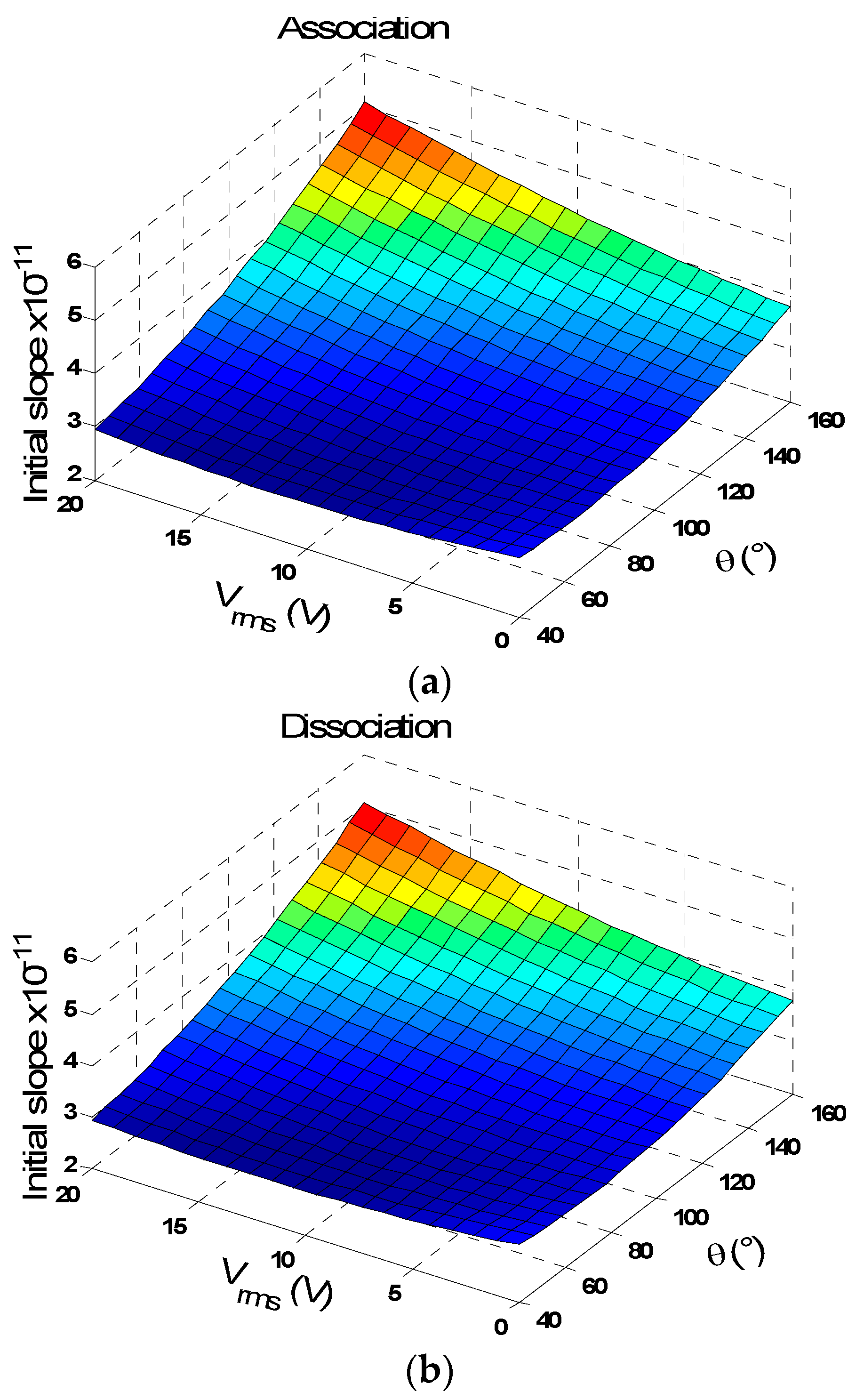
The initial slopes depend not only on the electrode aperture angles but also on the applied voltage. Figure 6 presents the three-dimensional surface plot of the slope at the origin of time related to the association and dissociation stages versus the applied voltage and the electrode aperture angle for a fixed value of the average inlet velocity uave = 100 µm/s. The large value of the initial slope was achieved for the largest applied voltage and for the largest electrode aperture angle.
Figure 6.
(a) Surface plot of initial slope related to the association and (b) dissociation stages versus applied voltage Vrms and the electrode aperture angle α = θ. The average inlet velocity is fixed at 100 µm/s. The initial slope for the both phases varies linearly with the applied voltage. The maximum of the initial slope is reached for Vrms = 15 V and α = θ = 160°.
Figure 7 illustrates the temperature rise versus the applied voltage and electrode aperture angle for uave = 100 µm/s. From this figure, it is noted that the temperature rise is strongly influenced by the applied voltage. However, the electrode aperture angle has a small and linear effect on the temperature rise.
Figure 7.
Surface plot of temperature rise versus the applied voltage Vrms and the electrode angle α = θ. The average inlet velocity is fixed at 100 µm/s.
Furthermore, it clearly appears that the temperature rise due to the Joule heating has a quadratic variation versus the applied voltage. This result is expected due to the source term in the heat equation. By increasing the angle θ, the electrode surface increases causing an increase in the electric field and subsequently the temperature. For example, the electrical field for Vrms = 15 V increases from 4 MV/m for θ = α = 40° to 6.2 MV/m for θ = α = 160°. Thus, there is an increase in Joule heating.
For microfluidic biosensors under AC electric field, the Joule heating could provoke an important temperature rise. The exceeding of the safe limit temperature can damage the thermally labile biological samples (say about 3 K) []. For this reason, it is necessary to work with a voltage lower than 15 V.
To avoid exceeding the limit temperature of the biological samples, we work at Vrms = 15 V. For this type of biosensor, the optimum efficiency is achieved for a larger electrode angle and high applied voltage.
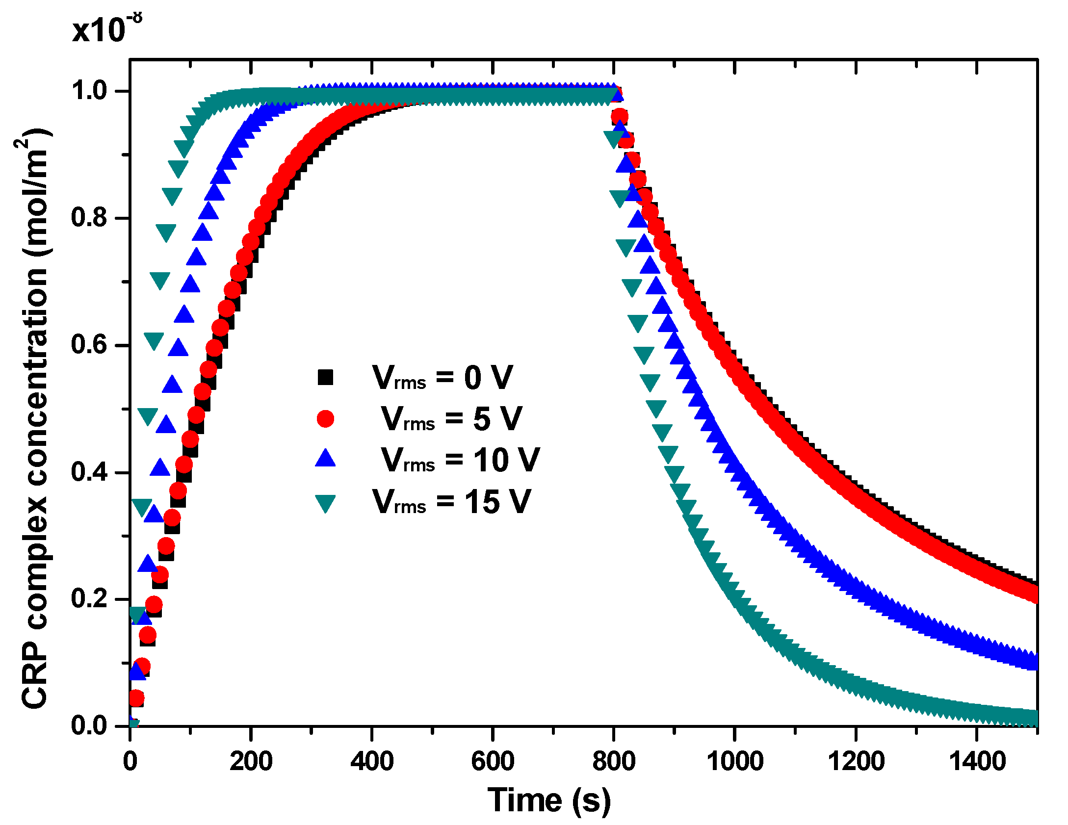
Figure 8 depicts the temporal evolution of average surface CRP complex concentration without and with electrothermal effect for uave = 100 µm/s. Three different AC voltages, 5, 10, and 15 V, were tested in this study. We noticed a significant improvement in reaction rate, especially for the larger applied voltage. For example, the increase rate of initial slope for the association phase was about 5% when the voltage Vrms increased from 0 to 5 V and 105% when the voltage Vrms increased from 10 to 15 V (Figure 9).
Figure 8.
Transient evolution of CRP complex concentration during the association and dissociation phases for several applied voltage Vrms from 0 to 15 V and for uave = 100 µm/s. The average inlet velocity is fixed at 100 µm/s.
Figure 9.
Initial slope related to association and dissociation phases of CRP complex versus the applied voltage. The average inlet velocity is fixed at 100 µm/s. The value of initial slope is calculated by choosing few of the initial points from the curves of Figure 8 then a linear interpolation by the least square method is used to compute the slope.
In Table 6, we calculated the temperature rise for different applied voltages. For Vrms = 15 V, ΔT = 3.0 K represents the limit value of the biological samples. Indeed, the maximum temperature rise obtained for the first model of the biosensor for α = θ = 160° is ΔT = 2.7 K under the same conditions of applied voltage and inlet velocity.
Table 6.
Enhancement factor for association and dissociation phases and temperature rise.
3.4. Effect of Inlet Velocity
To study the impact of the average inlet velocity on the response of both biosensor models, Figure 10 shows the evolution of the slope at the origin of time related to the association phase versus the average inlet velocity with and without electrothermal field. In absence of the electrothermal effect (i.e., Vrms = 0 V), increasing the flow velocity improves the convective mass transport of the analyte towards the sensitive surface and subsequently enhances the reaction rate. In Figure 10, the initial slope related to the association stage with electrothermal effect (Vrms = 15 V) for the first model of the biosensor is presented for α = θ = 160°.
Figure 10.
Comparison of the initial slope for both biosensor models versus the inlet velocity without and with applied voltage. For the first biosensor model, the applied voltage Vrms is fixed to 15 V whereas Vrms = 10 V for the second type. This intentional choice is made to show the efficiency and supremacy of the second geometry compared to the first one.
This figure exhibits two regions: a linear region for low inlet velocities and an almost saturation region for larger inlet velocities. In the first region, the reaction rate is greatly accelerated for any value of the applied voltage because the analyte in the bulk has time to diffuse to the reaction surface. In the second region, the enhancement factor of the binding reaction decreases because the amount of analyte carried by the flow is large []. We can conclude that the electrothermal effect is dominant for low inlet velocities and will be negligible for the large flow rates.
For comparison, the initial slope of the association phase for both biosensor models without and with electrothermal field versus the average inlet velocity reveals that the second model of biosensor is more efficient than the first one without and with an applied voltage.
4. Conclusions
The present paper performs three-dimensional simulations based on the finite element method and investigating the binding reaction kinetics of C-reactive protein CRP. A new microfluidic biosensor based on a novel reaction surface design without and with electrothermal force has been analyzed. Two reaction surface configurations have been studied: one in the form of a disc surrounded by two electrodes and the other in the form of a circular ring, one electrode of which is located inside the ring and the other outside. The effects of several important parameters were discussed, namely, the electrode angle, the applied voltage, the inlet flow velocity, and the reaction surface shape. The numerical results prove that the characteristics of the microfluidic biosensor can be further upgraded by using the second design of the sensing area (circular ring) coupled with the electrothermal force. In summary, the sensing area shape and the electrode location are able to improve the kinetic efficiency. The presented numerical simulation should be useful in designing microfluidic biosensors.
Author Contributions
Conceptualization, F.E. and T.A.-s.; methodology, F.E.; software, F.E.; validation, F.E., T.A.-s. and H.B.; writing—original draft preparation, F.E. and T.A.-s.; writing—review and editing, H.B.; visualization, F.E.; supervision, H.B.; project administration, T.A.-s.; funding acquisition, T.A.-s. All authors have read and agreed to the published version of the manuscript.
Funding
This research was funded by the Deanship of Scientific Research at Princess Nourah bint Abdulrahman University through the Fast-track Research Funding Program.
Institutional Review Board Statement
Not applicable.
Informed Consent Statement
Not applicable.
Data Availability Statement
Not applicable.
Acknowledgments
This research was funded by the Deanship of Scientific Research at Princess Nourah bint Abdulrahman University through the Fast-track Research Funding Program to support publication in the top journal (Grant no. 42-FTTJ-32).
Conflicts of Interest
The authors declare no conflict of interest.
References
- Cheng, S.-B.; Chen, M.-M.; Wang, Y.-K.; Sun, Z.-H.; Xie, M.; Huang, W. Current techniques and future advance of microfluidic devices for circulating tumor cells. TrAC Trends Anal. Chem. 2019, 117, 116–127. [Google Scholar] [CrossRef]
- Dabighi, A.; Toghraie, D. A new microfluidic device for separating circulating tumor cells based on their physical properties by using electrophoresis and dielectrophoresis forces within an electrical field. Comput. Methods Progr. Biomed. 2020, 185, 105147. [Google Scholar] [CrossRef]
- Luo, G.; Du, L.; Wang, Y.; Wang, K. Recent developments in microfluidic device-based preparation, functionalization, and manipulation of nano- and micro-materials. Particuology 2019, 45, 1–19. [Google Scholar] [CrossRef]
- Walczak, R.; Kawa, B.; Adamski, K. Inkjet 3D printed microfluidic device for growing seed root and stalk mechanical characterization. Sens. Actuators A Phys. 2019, 297, 111557. [Google Scholar] [CrossRef]
- Sheng, W.; Ogunwobi, O.O.; Chen, T.; Zhang, J.; George, T.J.; Liu, C.; Fan, Z.H. Capture, release and culture of circulating tumor cells from pancreatic cancer patients using an enhanced mixing chip. Lab Chip 2014, 14, 89–98. [Google Scholar] [CrossRef] [PubMed]
- Ding, R.; Lisak, G. Sponge-based microfluidic sampling for potentiometric ion sensing. Anal. Chim. Acta 2019, 1091, 103–111. [Google Scholar] [CrossRef]
- Santangelo, M.F.; Shtepliuk, I.; Filippini, D.; Ivanov, I.; Yakimova, R.; Eriksson, J. Real-time sensing of lead with epitaxial graphene-integrated microfluidic devices. Sens. Actuators B Chem. 2019, 288, 425–431. [Google Scholar] [CrossRef]
- Zheng, Z.; Wu, L.; Li, L.; Zong, S.; Wang, Z.; Cui, Y. Simultaneous and highly sensitive detection of multiple breast cancer biomarkers in real samples using a SERS microfluidic chip. Talanta 2018, 188, 507–515. [Google Scholar] [CrossRef] [PubMed]
- Ng, A.H.C.; Uddayasankar, U.; Wheeler, A.R. Immunoassays in microfluidic systems. Anal. Bioanal. Chem. 2010, 397, 991–1007. [Google Scholar] [CrossRef]
- Lebedev, K.; Mafe, S.; Stroeve, P. Convection, diffusion and reaction in a surface-based biosensor: Modeling of cooperativity and binding site competition on the surface and in the hydrogel. J. Colloid Interface Sci. 2006, 296, 527–537. [Google Scholar] [CrossRef]
- Hibbert, D.B.; Gooding, J.J.; Erokhin, P. Kinetics of Irreversible Adsorption with Diffusion: Application to Biomolecule Immobilization. Langmuir 2002, 18, 1770–1776. [Google Scholar] [CrossRef]
- Huang, K.-R.; Chang, J.-S.; Der Chao, S.; Wu, K.-C.; Yang, C.-K.; Lai, C.-Y.; Chen, S.-H. Simulation on binding efficiency of immunoassay for a biosensor with applying electrothermal effect. J. Appl. Phys. 2008, 104, 064702. [Google Scholar] [CrossRef]
- Hofmann, O.T.; Voirin, G.; Niedermann, P.; Manz, A. Three-Dimensional Microfluidic Confinement for Efficient Sample Delivery to Biosensor Surfaces. Application to Immunoassays on Planar Optical Waveguides. Anal. Chem. 2002, 74, 5243–5250. [Google Scholar] [CrossRef]
- Feldman, H.C.; Sigurdson, M.; Meinhart, C.D. AC electrothermal enhancement of heterogeneous assays in microfluidics. Lab Chip 2007, 7, 1553–1559. [Google Scholar] [CrossRef] [PubMed]
- Hart, R.; Lec, R.; Noh, H.M. Enhancement of heterogeneous immunoassays using AC electroosmosis. Sens. Actuators B Chem. 2010, 147, 366–375. [Google Scholar] [CrossRef]
- Liu, X.; Yang, K.; Wadhwa, A.; Eda, S.; Li, S.; Wu, J. Development of an AC electrokinetics-based immunoassay system for on-site serodiagnosis of infectious diseases. Sens. Actuators A Phys. 2011, 171, 406–413. [Google Scholar] [CrossRef]
- Mahmoodi, S.R.; Bayati, M.; Hosseinirad, S.; Foroumadi, A.; Gilani, K.; Rezayat, S.M. AC electrokinetic manipulation of selenium nanoparticles for potential nanosensor applications. Mater. Res. Bull. 2013, 48, 1262–1267. [Google Scholar] [CrossRef]
- Selmi, M.; Echouchene, F.; Belmabrouk, H.; Marwa, S.; Fraj, E.; Hafedh, B. Analysis of Microfluidic Biosensor Efficiency Using a Cylindrical Obstacle. Sens. Lett. 2016, 14, 26–31. [Google Scholar] [CrossRef]
- Selmi, M.; Echouchene, F.; Gazzah, M.H.; Belmabrouk, H. Flow Confinement Enhancement of Heterogeneous Immunoassays in Microfluidics. IEEE Sens. J. 2015, 15, 7321–7328. [Google Scholar] [CrossRef]
- Selmi, M.; Khemiri, R.; Echouchene, F.; Belmabrouk, H. Enhancement of the Analyte Mass Transport in a Microfluidic Biosensor by Deformation of Fluid Flow and Electrothermal Force. J. Manuf. Sci. Eng. 2016, 138, 081011. [Google Scholar] [CrossRef]
- Selmi, M.; Khemiri, R.; Echouchene, F.; Belmabrouk, H. Electrothermal effect on the immunoassay in a microchannel of a biosensor with asymmetrical interdigitated electrodes. Appl. Therm. Eng. 2016, 105, 77–84. [Google Scholar] [CrossRef]
- Echouchene, F.; Alshahrani, T.; Belmabrouk, H. Simulation of the Slip Velocity Effect in an AC Electrothermal Micropump. Micromachines 2020, 11, 825. [Google Scholar] [CrossRef] [PubMed]
- Huang, K.-R.; Chang, J.-S. Three dimensional simulation on binding efficiency of immunoassay for a biosensor with applying electrothermal effect. Heat Mass Transf. 2013, 49, 1647–1658. [Google Scholar] [CrossRef]
- Green, N.G.; Ramos, A.; González, A.; Castellanos, A.; Morgan, H. Electrothermally induced fluid flow on microelectrodes. J. Electrost. 2001, 53, 71–87. [Google Scholar] [CrossRef]
- Chou, C.; Hsu, H.-Y.; Wu, H.-T.; Tseng, K.-Y.; Chiou, A.; Yu, C.-J.; Lee, Z.-Y.; Chan, T.-S. Fiber optic biosensor for the detection of C-reactive protein and the study of protein binding kinetics. J. Biomed. Opt. 2007, 12, 024025. [Google Scholar] [CrossRef] [PubMed]
Publisher’s Note: MDPI stays neutral with regard to jurisdictional claims in published maps and institutional affiliations. |
© 2021 by the authors. Licensee MDPI, Basel, Switzerland. This article is an open access article distributed under the terms and conditions of the Creative Commons Attribution (CC BY) license (http://creativecommons.org/licenses/by/4.0/).