Article

A Numerical and Experimental Study on an Interconnected Metamaterial for Flexural Vibration Control Based on Modal Strain Energy

School of Mechanical Engineering, Gwangju Institute of Science and Technology (GIST), Gwangju 61005, Korea
*
Author to whom correspondence should be addressed.
Appl. Sci. 2021, 11(10), 4530; https://doi.org/10.3390/app11104530
Submission received: 7 April 2021 / Revised: 13 May 2021 / Accepted: 14 May 2021 / Published: 16 May 2021
(This article belongs to the Special Issue Vibration and Sound Control by Acoustic Meta Structures)

Abstract

:
In this study, an interconnected metamaterial was proposed to suppress flexural vibration. The interconnected metamaterial can improve the manufacturing and installation processes in terms of convenience because it can be fabricated in the form of a modular multi-celled structure with a single-phase material. To evaluate the vibration reduction performance of the metamaterial, stopband analysis was performed, as it solves an iterative eigenvalue problem for the wave vector domain. In order to identify the Bloch mode that contributes to flexural vibration, a concept to extract the Bloch mode based on the modal strain energy was proposed. The vibration-reduction performance of the interconnected metamaterial was numerically verified by using a frequency-response analysis of the multi-celled structure. The interconnected metamaterial proposed in this study was fabricated by using a 3D printer. Finally, the vibration-reduction performance of the multi-celled structure was experimentally verified by using impact testing.

Graphical Abstract

1. Introduction

Metamaterials are structures engineered to have wave-propagation characteristics that do not exist in nature [1,2,3,4]. An acoustic metamaterial was first proposed by Liu et al. in 2000 and has been studied in various fields such as sound radiation, weave guides, transmission loss, and vibration reduction for several decades [5].
Regarding vibration suppression, the working principles of acoustic metamaterials are mainly categorized into an anti-resonant mode and stopband. In 2013, Varanasi et al. proposed an analysis model of a metamaterial-based noise barrier that increases the sound transmission loss in the low-frequency range with anti-resonance [6]. In 2017, the noise reduction performance of this noise barrier was experimentally verified in a diffused field [7]. In 2019, Kim et al. proposed a design optimization method that maximized the sound transmission loss at the target frequency [8]. However, an anti-resonance-based design method generally requires relatively expensive computational resources to analyze the entire periodic structure. Using the stopband analysis, the response of the entire structure can be determined by the numerical analysis for the unit-cell structure [9,10,11,12,13]. According to Bloch’s theorem, the response of a multi-celled structure consisting of a periodically repeated unit cell is expressed as the product of a periodic function and a plane wave [10]. Using the Floquet–Bloch boundary condition based on the Bloch theorem, each boundary of the unit cell structure is characterized by a wave vector. Stopband analysis is an iterative eigenvalue analysis of periodic boundary conditions determined by each wave vector. Using stopband analysis of the unit-cell structure, a stopband in which no vibration mode exists for all wave vectors can be calculated, and the vibration is not propagated within the frequency range of the stopband [9,10,11,14].
Several studies on locally resonant metamaterials using stopband analysis for attenuating structural vibrations have been conducted. In 2012, Liu and Hussein developed an analytical model for calculating the stopband of a beam-shaped periodic structure [15]. In 2019, Jung et al. proposed locally resonant metamaterials based on panel springs comprising acrylic plastic and magnets [11]. This locally resonant metamaterial was applied to the vehicle dash panel to reduce the vibration and radiated noise of the panel. In 2020, a genetic-algorithm-based topology optimization method for a locally resonant metamaterial was proposed to tailor the stopband in the target frequency band [10].
In this work, an interconnected metamaterial in which the resonators of each unit structure are connected was proposed. The interconnected metamaterial is possible to be fabricated by modular manufacturing with single-phase materials. It is relatively advantageous to be applied to industrial applications. However, due to the interaction of each resonator, vibrational waves in interconnected metamaterials propagates not only through the host structure but also through the resonators. To suppress a flexural vibration with the metamaterial, a stopband should be calculated by extracting the Bloch mode that contributes to the bending mode of the host structure from the other modes. In 2006, a modal strain energy-based decomposition method was developed for damage localization of 3D frames [16]. In 2020, Brethm et al. developed an automation selection algorithm that selects the appropriate vibration mode, using the modal strain energy and modal assurance criteria [17]. As shown in these two kinds of works in the literature, it is possible to classify the Bloch modes concerning the dynamic property of the mode shape. Moreover, applying these locally resonant metamaterials to practical industrial problems is a difficult task. Furthermore, manufacturing them by general manufacturing processes such as casting or stamping is challenging because almost of locally resonant metamaterials have complicated shapes and consist of multiple materials [18,19,20,21,22]. In addition, because each unit-cell structure must be attached to the host structure with a regular unit-cell size, installing this type of metamaterial requires considerable effort.
In this work, we proposed the systematic method to evaluate the stopband of an interconnected metamaterial based on modal strain energy. The unit structure is divided into resonator and host structure, and modal strain energy for each part is calculated to separate the Bloch mode that contributes to the flexural wave was extracted from among the Bloch modes. The interconnected metamaterial can be fabricated by a modular manufacturing process that uses a single-phase material. The interconnected metamaterial proposed in this study is composed of only polylactic acid (PLA) plastic and can be manufactured by injection molding. Since the molds have been expensive to manufacture, a 3D printer was used in this work. Because the multi-celled structure comprising a unit cell is manufactured at once, the effort incurred during the installation process can be effectively reduced. In Section 2, stopband analysis for interconnected metamaterial unit-cell structures and frequency-response analysis for multi-celled structures are described. Section 3 describes the 3D-printer-based manufacturing methods and experiments conducted to validate the vibration-reduction performance of the interconnected metamaterial.

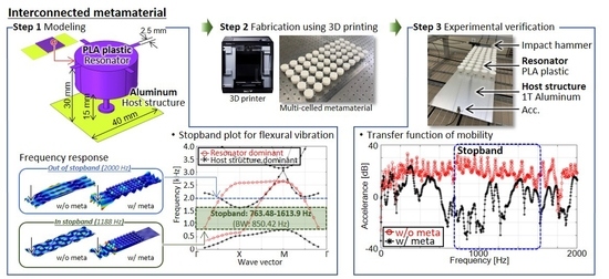
2. Finite Element Modeling of Interconnection Metamaterial

In this section, a numerical analysis of interconnected metamaterials is presented. First, a stopband in which the flexural vibration is suppressed in the host structure is calculated. Then, frequency response analysis was performed to validate the vibration-reduction performance in the frequency range of the stopband.

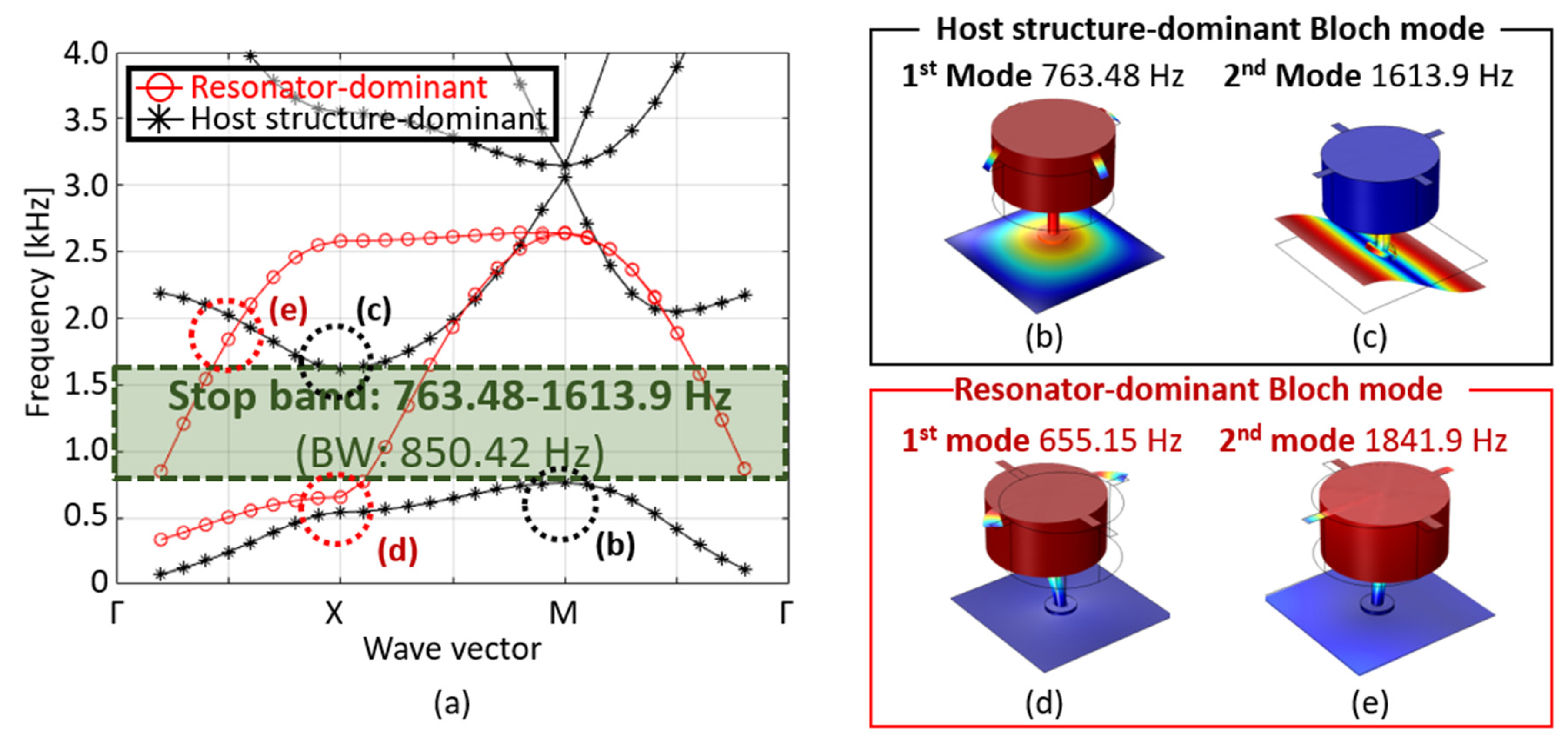
2.1. Stopband Analysis of Interconnected Metamaterials

In this subsection, we discuss the stopband analysis of interconnected metamaterials. Figure 1 shows a conceptual diagram of the interconnected metamaterial.
Figure 1a shows the size of the interconnected metamaterial. The host structure is an aluminum plate with 1T thickness, and the resonator part is PLA plastic. The mass of the resonator is determined by d 1 and h 1 , while the stiffness of the resonator is determined by d 2 and h 2 . The parameter w b e a m affects the interaction of each resonator. As d 1 and h 1 increase, the mass of the resonator increases, and the frequency width of the stopband can be changed. The stiffness of the metamaterial depends on the radius and height of the neck beam. By changing of d 2 and h 2 , the stiffness of resonator can be changed. The geometrical parameters used in this work are shown in Table 1.
As shown in Figure 1b, the interconnected part of the resonator ( Ω res , shell ) and host structure ( Ω host , shell ) are composed of shell elements, and the remaining resonator ( Ω res , solid ) domain comprises solid elements. At the solid–shell coupling boundary ( Ω solid - shell ), the solid and shell elements share the same displacement.
u shell u solid = 0   at   Ω solid - shell .
Table 2 shows the mechanical properties of aluminum and PLA plastic that make up the host structure and resonator.
Figure 2 describes the Floquet–Bloch boundary condition for stopband analysis. Figure 2a shows a schematic diagram explaining the Floquet–Bloch boundary condition. The multi-celled structure is a periodic structure in which the unit-cell structure is infinitely repeated along with the a1 and a2 directions. The unit-cell structure has a length of L in the x- and y-directions, and each unit structure comprises a host structure and a resonator. Each resonator is linked with adjacent resonators. Because of the spatial periodicity of the multi-celled structure, the unit-cell structure follows the Bloch theorem. The Floquet–Bloch boundary condition can be expressed as follows:
u ( r A ) = u ( r B + a ) = u ( r B + a 1 + a 2 ) = u ( r B ) e j ( k x a 1 + k y a 2 )
where u ( r A ) and u ( r B ) are the displacement responses at points A and B, respectively. The function e j ( k x a 1 + k y a 2 ) represents the spatial periodicity, expressed by the wave vector k. The Floquet–Bloch boundary condition was applied to consider the spatial periodicity of this metamaterial. According to Equation (2), the three left/top boundaries ( Γ T , host , Γ RT , host , Γ R , host ) of the host structure in Figure 2b are represented by five remaining boundaries ( Γ LT , host , Γ L , host , Γ LB , host , Γ B , host , Γ RB , host ), and the two left/bottom boundaries ( Γ L , res , Γ B , res ) of the resonator are represented by two right/top boundaries ( Γ R , res , Γ T , res ). According to Equation (2), each boundary condition is expressed as follows [9,10,11]:
u R , host = u L , host e j k x L u T , host = u B , host e j k y L u RB , host = u LB , host e j k x L u LT , host = u LB , host e j k y L u RT , host = u LB , host e j ( k x L + k y L ) u R , res = u L , res e j k x L u T , res = u B , res e j k y L
where u host and u res are the displacements of the host structure and resonator, respectively. The constant L is the length of the unit-cell structure. Equation (3) can be expressed in matrix form as follows:
I ( k ) u ˜ = 0 where   I ( k ) = [ e j k x L 1 0 0 0 0 e j k y L 1 0 ( 2 × 4 ) 0 ( 2 × 4 ) 0 ( 2 × 4 ) e j k x L 1 0 0 0 0 e j k y L 1 0 ( 2 × 4 ) 0 ( 3 × 4 ) 0 ( 3 × 4 ) e j k x L 1 e j k x L 0 e j k x L 0 0 0 1 0 0 1 ] u ˜ = [ u L , res u R , res u B , res u T , res u L , host u R , host u B , host u T , host u LB , host u RB , host u LT , host u RT , host ]
where u ˜ is the displacement vector comprising the displacement responses of the host structure and resonator. According to the Lagrange multiplier method, the eigenvalue problem for the augmented system can be expressed as follows:
[ K aug ω 2 M aug ] u aug = 0 where   K aug = [ K I ( k ) T I ( k ) 0 ] ,   M aug = [ M 0 0 0 ] ,   K aug = [ u λ ]
where K aug and M aug are the augmented stiffness and mass matrices, respectively. The variable ω and vector u are the natural frequency and displacement of the wave vector k ( k x , k y ) , respectively. The vector u aug is an augmented displacement vector comprising the displacement vector u and the Lagrange multiplier λ . Substituting I ( k ) in Equations (4) and (5), the stopband of the interconnected metamaterial can be calculated by using the iterative eigenvalue problem for each wave vector. The iterative solution obtained from Equation (5) indicates the modal frequencies for the variation in the wave vector. The modal frequency is the Bloch mode for propagating the vibration. In contrast, flexural waves are not propagated in the stopband, which is a frequency band in which the vibrating mode does not exist for all wave vectors. Considering the spatial periodicity of the interconnecting metamaterial, Equation (4) only calculates the wave vector domain for the unit structure, not the entire periodic structure. According to the symmetry of the unit-cell structure, the wave vector domain of the unit-cell structure can be reduced to the irreducible Brillouin zone (IBZ) defined in Figure 3 [2].
In this study, we considered the unit-cell structure in the form of a square of length L. Thus, the IBZ has the shape of a triangle made up of three points, Γ ( 0 , 0 ) , X ( π L , 0 ) , and M ( π L , π L ) . The dispersion diagram of the interconnected metamaterial represents the set of iterative solutions for the eigenvalue problem in Equation (5) with the wave-vector domain.
Figure 4 shows the dispersion diagram and Bloch modes calculated from stopband analysis for the unit structure of the interconnected metamaterial. The Bloch mode ω of the interconnected metamaterial is divided into the host structure dominant Bloch mode, ω host , which contributes to the transmission of the bending vibration of the host structure, and the resonator dominant Bloch mode, ω res , which does not directly contribute to the transmission of bending vibration. Therefore, the Bloch mode for the stopband which reduces the flexural vibration is determined by the host structure dominant Bloch mode, which is determined by the modal strain energy, as follows:
ω = ω host   ( E res E host ) ω = ω res   ( E res > E host )
where E host and E res are the modal strain energies calculated for the host structure and resonator, respectively. The modal strain energies calculated in the host structure and resonator can be expressed as follows [17].
E host = Ω host , shell 1 2 Ψ j T K Ψ j d Ω E res = Ω res , shell 1 2 Ψ j T K Ψ j d Ω + Ω res , solid 1 2 Ψ j T K Ψ j d Ω
where Ψ j is the displacement vector in the jth Bloch mode. As mentioned in the description of Figure 1, Ω host , shell , Ω res , shell and Ω res , solid are the shell boundaries of the host structure, interconnecting shell, and the solid domain of the resonator, respectively. As shown in Figure 4b,c, the modal strain energy of the host structure ( Ω host , shell ) is larger than that of the resonator because the deformation of the host structure is dominant. Thus, the Bloch modes in Figure 4b,c are the host-structure-dominant modes. The Bloch modes in Figure 4d,e are the resonator-dominant Bloch modes because the modal strain energy of the resonator ( Ω res , shell + Ω res , solid ) is relatively larger than that of the host structure. Details on extracting the host-structure-dominant Bloch mode are described in the Appendix A. The stopband for attenuating the flexural vibration can be determined by using the host-structure-dominant Bloch mode. As shown in Figure 4a, the interconnected metamaterial proposed in this study has a stopband from 763.48 to 1613.9 Hz. In this frequency range, the flexural vibration of the host structure with multi-celled metamaterials cannot be propagated because of the effect of the local resonance of each resonator.

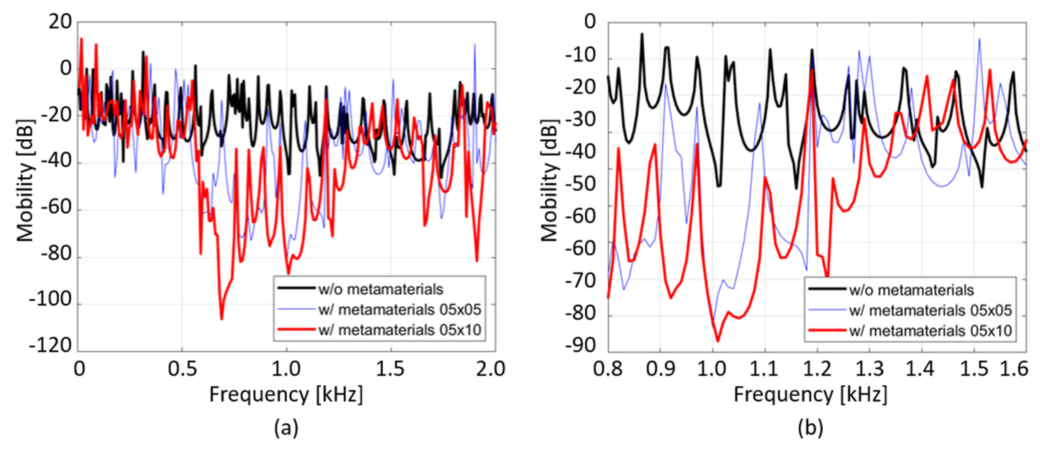
2.2. Frequency Response Analysis for Multi-Celled Interconnected Metamaterial

The frequency response analysis for the multi-celled metamaterial is implemented to verify the vibration-reduction performance in the frequency range of the stopband [23] in this subsection. Considering the computational cost, the size of the unit cell used to analyze the frequency response analysis of the multi-celled structure was determined to be 5 × 5 and 5 × 10. The multi-celled interconnected metamaterials of sizes 5 × 5 and 5 × 10 were attached to a plate of 800 mm × 200 mm, and each vibration response was compared. As shown in Figure 5, point excitation was performed at the center point of one edge along the z-direction, and the mobility response along the normal direction was calculated at the center point of the opposite direction.
Figure 6 shows the transfer function of the z-directional mobility calculated at each measuring point, as shown in Figure 5. As shown in Figure 4, the stopband of the interconnected metamaterial proposed in this study ranges from 763.48 to 1613.9 Hz. In this frequency range, the mobility of the bare plate decreases 17.5, 22.6 dB on average by attaching the multi-celled metamaterial of sizes 5 × 5 and 5 × 10. As shown in Figure 6, the flexural vibration-reduction performance of the 5 × 10 multi-celled structure is better than that of the 5 × 5 structure. Thus, as the size of the array increases, the vibration transmission of the structure decreases.
Figure 7 is the z-directional displacement response at 1188 and 2000 Hz calculated from the frequency response analysis model shown in Figure 5. In Figure 7a,b, the vibration generated in the excitation point of the bare plate is propagated on the whole structure regardless of the stopband. As shown in Figure 7c,e, the flexural vibration at the excitation point cannot be propagated because of the effect of the interconnected metamaterial. It is also not transmitted to the measurement point. In contrast, as shown in Figure 7d,f, the vibration of the excitation point is propagated to the entire host structure in the frequency range out of the stopband. Each resonator in the stopband locally resonates and dissipates the vibration energy, and vibration cannot be propagated.

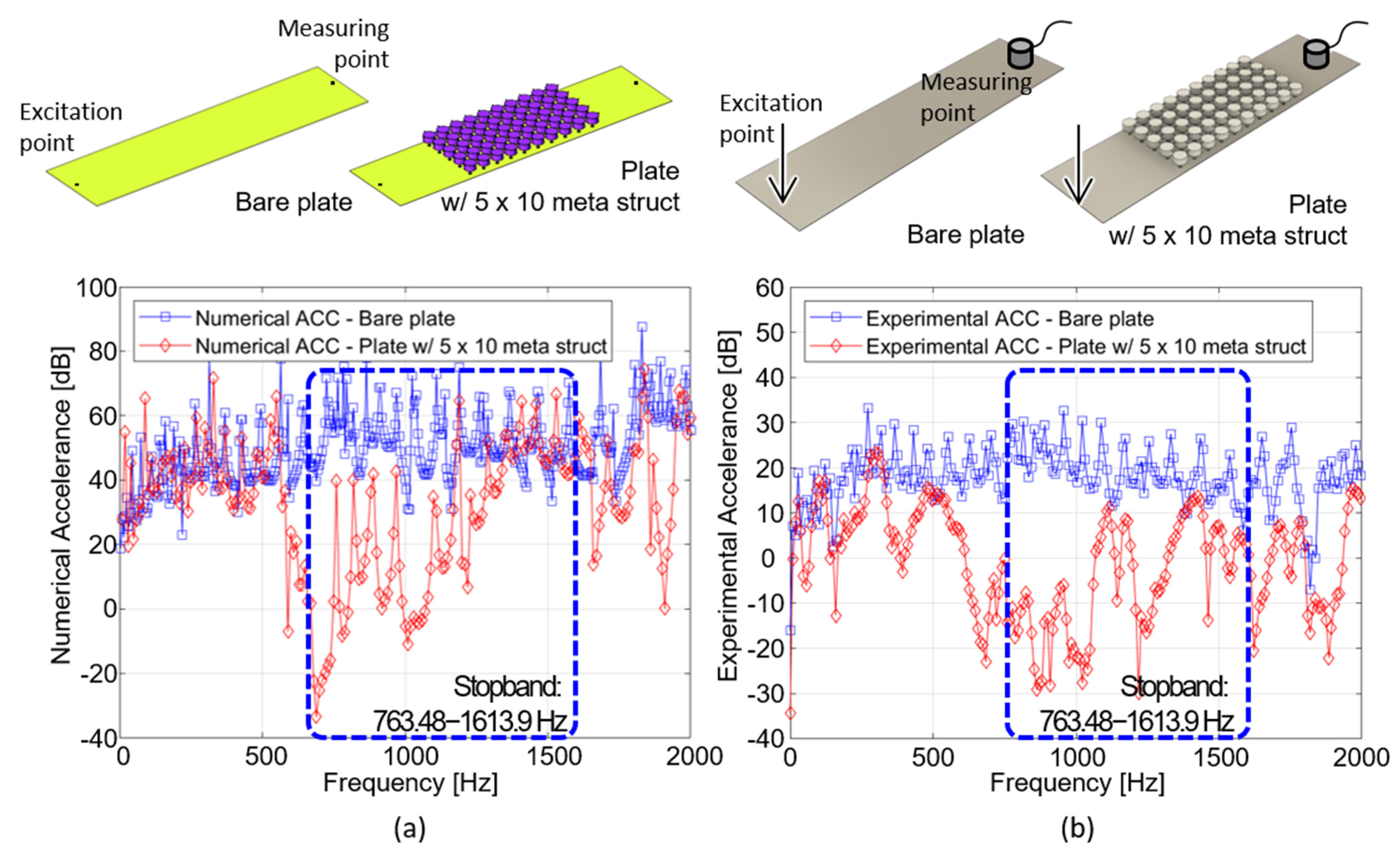
3. Fabrication and Experimental Verification of Interconnected Metamaterials

We describe the stopband analysis for attenuating flexural vibration and the frequency response analysis performed to verify the vibration reduction performance of the stopband in the previous section. In Section 3, we experimentally verify the vibration-reduction performance of the multi-celled interconnected metamaterial. For vibration testing, a multi-celled structure was fabricated by using a 3D printer. Figure 8 describes the manufacturing process for the multi-celled interconnected metamaterial.
Figure 8a shows the resonator part used in the finite element analysis model. As mentioned in Section 2.1, the resonator part included a combination of solid and shell elements, considering the computational cost. As shown in Figure 8b, to 3D print the multi-celled metamaterial, the metamaterial was modified by using the numerical analysis model. In this study, Sindoh 3D 2X was used to fabricate the multi-celled metamaterial. The geometrical size of the model to be manufactured must be smaller than 228 mm × 200 mm × 300 mm, which is the size of the 5 × 5 multi-celled structure. Considering constraints in manufacturing, the multi-celled structure of the 5 × 5 module was fabricated twice to make a 5 × 10 structure. Figure 8c shows the multi-celled structure fabricated by the 3D printer. The printer setting used in this manufacturing are shown in Table 2. Because the resonator part of the finite element model of the interconnected metamaterial is composed of an isotropic material, it must be manufactured with an ‘infill’ set to 100%. As the interconnecting element is modeled as a 1T shell, the height of each layer was set to 0.2 mm for stable lamination. The printing velocity was set to 40 mm/s. Increasing the printing velocity and layer height can reduce the working time, but it also reduces the quality of the product. If the infill density is lowered, the manufacturing speed increases, but the dynamic characteristics of the structure are significantly changed because empty spaces occur inside the resulting structure. Therefore, for 3D-printer-based manufacturing, the stetting parameters should be carefully determined considering the shape and size of the structure. Using the printer settings in Table 3, one module includes 154 layers, and manufacturing requires 53 h 10 m. Figure 8d shows the schematics used for assembling multi-celled metamaterials. As shown in Figure 8c,d, The multi-celled metamaterial of Figure 8c is attached to the aluminum plate of 1T thickness, using an adhesive layer.
Figure 9 shows the experimental setup for impact testing to verify the vibration-reduction performance of multi-celled interconnected metamaterials. The multi-celled metamaterial fabricated by a 3D printer was attached to the center of a 1T thick aluminum plate with dimensions of 200 mm × 800 mm. The vibration responses of the bare plate and the plate with a 5 × 10 multi-celled structure were compared. As shown in Figure 9, the excitation force was imposed at the end of the plate, and the vibration response was measured at the center of the other side. In this experiment, the excitation force was imposed by using an impact hammer (PCB model086C03), and the vibration signal was measured by using an accelerometer (Brüel & Kjær Type 4394) [11]. The LMS SCADAS DAQ equipment was used to collect and process the excitation force and vibration signals.
Figure 10 shows the results of the frequency response analysis proposed in Figure 5 and impact testing performed with the setup shown in Figure 9. The interconnected metamaterial proposed in this study has a stopband in the frequency range of 764–1613 Hz. As shown in Figure 6 and Figure 7, flexural vibration of the multi-celled metamaterial is suppressed in the frequency band of the stopband. Figure 10a,b show that the accelerance is numerically/experimentally reduced by an average of approximately 22.9 and 24.1 dB in the frequency range of the stopband. As shown in Figure 10b, peak/dip frequencies are different with numerical result in Figure 10a and the vibration reduction performance measured by impact testing is slightly larger than numerical simulation in Figure 10a. The reason why the numerical/experimental results are different is due to the unavoidable uncertainty in the process of assembling the meta structure and the printing process of the 3D printer [24,25]. Due to the additional damping effect of the adhesive layer, numerical noise reduction performance in Figure 10a is different with the experimental result in Figure 10b. Since thermal deformation is generated in 3D-printing process, the dynamic stiffness of metamaterial could be changed. Despite the various uncertainties, the experimental results show that the numerical model is sufficient to account for the physical phenomena.

4. Conclusions

In this study, an interconnected metamaterial was proposed to reduce bending vibration. In contrast with conventional acoustic metamaterials, which are individually manufactured and attached to the host structure, a multi-celled structure was fabricated with a single-phase material and applied to the vibrating structure. Thus, the convenience for manufacturing and installation was remarkably improved. The stopband for attenuating the flexural vibration of the host structure was determined by the host-structure-dominant Bloch mode, not the resonator-dominant Bloch mode. We also proposed a method to extract the host-structure-dominant Bloch mode by using modal strain energy to calculate the stopband for attenuating the flexural vibration. The vibration reduction performance of the interconnected metamaterial was numerically verified using the frequency response analysis of a multi-celled metamaterial. A 5 × 5 multi-celled structure was fabricated by using a 3D printer, and the vibration-reduction performance of the interconnected metamaterial was experimentally verified by using impact testing. In this study, a multi-celled interconnected metamaterial was produced by using a 3D printer, but it can be mass-produced by using the casting process. The interconnected metamaterial can be applied to various mechanical systems such as automobiles and home appliances to create a comfortable driving environment and improve system stability.

Author Contributions

Conceptualization, H.-G.K.; methodology, H.-G.K. and S.W.; software, H.-G.K.; validation, H.-G.K. and S.W.; formal analysis, H.-G.K.; investigation, O.J.; writing—original draft preparation, H.-G.K.; writing—review and editing, H.-G.K. and O.J.; supervision, S.W.; project administration, H.-G.K.; funding acquisition, S.W. All authors have read and agreed to the published version of the manuscript.

Funding

This work was supported by GIST Young Scientist Research Project grant funded by the GIST in 2021.

Institutional Review Board Statement

Not applicable.

Informed Consent Statement

Not applicable.

Data Availability Statement

All data in this paper are available; there are no additional data.

Acknowledgments

This work was supported by GIST Young Scientist Research Project grant funded by the GIST in 2021.

Conflicts of Interest

The authors declare no conflict of interest.

Appendix A

The modal-strain-energy-based method for extracting the band that contributes to flexural vibration from the eigenvalues of the stopband plot is described in Section 2.1. Figure A1 shows a conceptual diagram of how to classify the iterative solution into host-structure-dominant and resonator-dominant Bloch modes. The stopband plot shown in Figure A1a shows a solution to the iterative eigenvalue problem for the wave vector domain. Figure A1b shows the modal strain energy for the host structure and resonator, E host and E res , at the eigenvalue frequency calculated for k x = 78.5   rad / m and k y = 15.7   rad / m , respectively. As shown in Figure A1b, the first, third, and fifth Bloch modes for this wave vector are the host-structure-dominant Bloch modes, ω host , because the modal strain energy of the host structure is larger than that of the resonator. The host-structure-dominant Bloch modes are shown in Figure A1c. In contrast, in the case of the second and fourth orders, these Bloch modes are the resonator-dominant Bloch mode, ω res , because the modal strain energy of the resonator is relatively large. The resonator-dominant Bloch modes are shown in Figure A1d. In contrast with the resonator-dominant Bloch mode, the deformation of the host structure is dominant in the host-structure-dominant mode of Figure A1d. Therefore, the flexural vibration of the host structure is reduced in the frequency band of the stopband calculated from the host-structure-dominant Bloch mode.
Figure A1. Schematic diagram of the separation of the host-structure- and resonator-dominant Bloch modes: (a) stopband plot of the interconnected metamaterial; mode shape of (b) the host-structure-dominant Bloch mode, ω h o s t ; (c) the resonator dominant Bloch mode, ω r e s ; and (d) modal strain energy calculated in the host structure/resonator domain for each mode at the wave vectors of k x = 78.5   r a d / m and k y = 15.7   r a d / m .
Applsci 11 04530 g0a1

References

  1. Askari, M.; Hutchins, D.A.; Thomas, P.J.; Astolfi, L.; Watson, R.L.; Abdi, M.; Ricci, M.; Laureti, S.; Nie, L.; Freear, S. Ad-ditive manufacturing of metamaterials: A review. Addit. Manuf. 2020, 36, 101562. [Google Scholar]
  2. Craster, R.V.; Guenneau, S. Acoustic Metamaterials: Negative Refraction, Imaging, Lensing and Cloaking; Springer: Amsterdam, The Netherlands, 2012. [Google Scholar]
  3. Sharma, G.S.; Skvortsov, A.; MacGillivray, I.; Kessissoglou, N. Sound scattering by a bubble metasurface. Phys. Rev. B 2020, 102, 214308. [Google Scholar] [CrossRef]
  4. Sharma, G.S.; Skvortsov, A.; MacGillivray, I.; Kessissoglou, N. On superscattering of sound waves by a lattice of disk-shaped cavities in a soft material. Appl. Phys. Lett. 2020, 116, 041602. [Google Scholar] [CrossRef]
  5. Liu, Z.; Zhang, X.; Mao, Y.; Zhu, Y.Y.; Yang, Z.; Chan, C.T.; Sheng, P. Locally resonant sonic materials. Science 2000, 289, 1734–1736. [Google Scholar] [CrossRef]
  6. Varanasi, S.; Bolton, J.S.; Siegmund, T.H.; Cipra, R.J. The low frequency performance of metamaterial barriers based on cellular structures. Appl. Acoust. 2013, 74, 485–495. [Google Scholar] [CrossRef] [Green Version]
  7. Varanasi, S.; Bolton, J.S.; Siegmund, T. Experiments on the low frequency barrier characteristics of cellular metamaterial panels in a diffuse sound field. J. Acoust. Soc. Am. 2017, 141, 602–610. [Google Scholar] [CrossRef] [PubMed] [Green Version]
  8. Kim, H.-G.; Goo, S.; Jung, J.; Wang, S. Design optimization of a cellular-type noise insulation panel to improve transmis-sion loss at low frequency. J. Sound Vib. 2019, 447, 105–119. [Google Scholar] [CrossRef]
  9. Jung, J.; Goo, S.; Wang, S. Investigation of flexural wave band gaps in a locally resonant metamaterial with plate-like resonators. Wave Motion 2020, 93, 102492. [Google Scholar] [CrossRef]
  10. Jung, J.; Goo, S.; Kook, J. Design of a local resonator using topology optimization to tailor bandgaps in plate structures. Mater. Des. 2020, 191, 108627. [Google Scholar] [CrossRef]
  11. Jung, J.; Kim, H.-G.; Goo, S.; Chang, K.-J.; Wang, S. Realisation of a locally resonant metamaterial on the automobile pan-el structure to reduce noise radiation. Mech. Syst. Signal Process. 2019, 122, 206–231. [Google Scholar] [CrossRef]
  12. Sanchez-Perez, J.V.; Rubio, C.; Martinez-Sala, R.; Sanchez-Grandia, R.; Gomez, V. Acoustic barriers based on periodic arrays of scatterers. Appl. Phys. Lett. 2002, 81, 5240–5242. [Google Scholar] [CrossRef]
  13. Sharma, G.S. Acoustic Performance of Periodic Composite Materials. In Proceedings of the Acoustics 2015 Hunter Valley, Harrogate, UK, 15–18 November 2015; 2015. [Google Scholar]
  14. Hussein, M.I. Reduced Bloch mode expansion for periodic media band structure calculations. Proc. R. Soc. A Math. Phys. Eng. Sci. 2009, 465, 2825–2848. [Google Scholar] [CrossRef] [Green Version]
  15. Liu, L.; Hussein, M.I. Wave motion in periodic flexural beams and characterization of the transition between Bragg scattering and local resonance. J. Appl. Mech. 2012, 79, 011003. [Google Scholar] [CrossRef]
  16. Li, H.; Yang, H.; Hu, S.-L.J. Modal strain energy decomposition method for damage localization in 3D frame structures. J. Eng. Mech. 2006, 132, 941–951. [Google Scholar] [CrossRef]
  17. Brehm, M.; Zabel, V.; Bucher, C. An automatic mode pairing strategy using an enhanced modal assurance criterion based on modal strain energies. J. Sound Vib. 2010, 329, 5375–5392. [Google Scholar] [CrossRef]
  18. Hu, W.; Ren, Z.; Wan, Z.; Qi, D.; Cao, X.; Li, Z.; Wu, W.; Tao, R.; Li, Y. Deformation behavior and band gap switching function of 4D printed multi-stable metamaterials. Mater. Des. 2021, 200, 109481. [Google Scholar] [CrossRef]
  19. Gorshkov, V.; Sareh, P.; Navadeh, N.; Tereshchuk, V.; Fallah, A.S. Multi-resonator metamaterials as multi-band meta-structures. Mater. Des. 2021, 202, 109522. [Google Scholar] [CrossRef]
  20. An, X.; Lai, C.; Fan, H.; Zhang, C. 3D acoustic metamaterial-based mechanical metalattice structures for low-frequency and broadband vibration attenuation. Int. J. Solids Struct. 2020, 191–192, 293–306. [Google Scholar] [CrossRef]
  21. Huang, T.-Y.; Shen, C.; Jing, Y. Membrane- and plate-type acoustic metamaterials. J. Acoust. Soc. Am. 2016, 139, 3240–3250. [Google Scholar] [CrossRef] [Green Version]
  22. Elford, D.P.; Chalmers, L.; Kusmartsev, F.V.; Swallowe, G.M. Matryoshka locally resonant sonic crystal. J. Acoust. Soc. Am. 2011, 130, 2746–2755. [Google Scholar] [CrossRef] [Green Version]
  23. Comsol Multiphysics Users Guide. 2011. Available online: https://blogs.ethz.ch/ps_comsol/files/2020/05/COMSOLMultiphysicsUsersGuide.pdf (accessed on 15 May 2021).
  24. Tofangchi, A.; Han, P.; Izquierdo, J.; Iyengar, A.; Hsu, K. Effect of ultrasonic vibration on interlayer adhesion in fused fila-ment fabrication 3D printed ABS. Polymers 2019, 11, 315. [Google Scholar] [CrossRef] [PubMed] [Green Version]
  25. Sharma, G.S.; Faverjon, B.; Dureisseix, D.; Skvortsov, A.; MacGillivray, I.; Audoly, C.; Kessissoglou, N. Acoustic performance of a periodically voided viscoelastic medium with uncertainty in design parameters. J. Vib. Acoust. 2020, 142, 061002. [Google Scholar] [CrossRef]
Figure 1. Conceptual diagram of an interconnected metamaterial; (a) dimension and material of host structure (yellow) and resonator (violet); (b) layout of a unit-cell structure and element type for each component.
Applsci 11 04530 g001
Figure 2. Schematic diagram describing (a) the Floquet–Bloch boundary condition of the unit-cell structure and each boundary of (b) the host structure and (c) resonator.
Applsci 11 04530 g002
Figure 3. The irreducible Brillouin zone (IBZ) in the wave vector domain of a unit-cell structure.
Applsci 11 04530 g003
Figure 4. Dispersion diagram of the interconnected metamaterial: (a) stopband plot with host structure dominant (black star line) and resonator dominant (red circle line) bands; (b,c) are host structure dominant Bloch modes; (d,e) are resonator dominant Bloch modes.
Applsci 11 04530 g004
Figure 5. Frequency response analysis of plates (a) without and with interconnected metamaterials of sizes (b) 5 × 10 and (c) 10 × 10.
Applsci 11 04530 g005
Figure 6. Frequency response of z-directional mobility of the bare plate and plate with interconnected 5 × 10 and 10 × 10 metamaterials for (a) 0~2000 Hz and (b) the stopband (764–1613 Hz).
Applsci 11 04530 g006
Figure 7. Displacement field of a multi-celled interconnected metamaterial along the z-direction at 2000 Hz (out of stopband) and 1188 Hz (center frequency of stopband); frequency response of (a) bare plate, plates with (c) 5 × 5 and (e) 5 × 10 metamaterials at 1188 Hz; frequency response of (b) bare plate, plates with (d) 5 × 10 and (f) 10 × 10 metamaterials at 2000 Hz.
Applsci 11 04530 g007
Figure 8. Fabrication process of the interconnected metamaterial, using (a) a numerical analysis model; (b) modified model for additive manufacturing; (c) assembly scheme of the 5 × 5 multi-celled metamaterial and host structure; (d) assembly schematics of metamaterial.
Applsci 11 04530 g008
Figure 9. Experimental setup with multi-celled interconnected metamaterial structure.
Applsci 11 04530 g009
Figure 10. Accelerance transfer function between the excitation and measuring points in 1 T aluminum plates with/without the 5 × 10 interconnected metamaterials: (a) calculated form frequency response analysis and (b) measured by impact testing.
Applsci 11 04530 g010
Table 1. Geometrical parameters of the interconnected metamaterial.
ParameterValue (mm)
d 1 25
d 2 3
h 1 15
h 2 15
w b e a m 2.5
Table 2. Mechanical properties of the resonator and host structure.
ResonatorHost Structure
TypePLA plasticAluminum
Elastic modulus (GPA)4.1671.89
Poisson’s ratio (1)0.4030.284
Density (kg/m3)14002669
Table 3. Settings of 3D printer used to fabricate multi-celled interconnected metamaterials.
PropertiesValues
Infill density100%
Layer height0.2 mm
Printing velocity40 mm/s
Fixing bedRaft
Publisher’s Note: MDPI stays neutral with regard to jurisdictional claims in published maps and institutional affiliations.

