Article

Partial Energy Transfer Model of Lamb Waves Scattering in Materially Isotropic Waveguides

1
Department of Control Systems and Instrumentation, Faculty of Mechanical Engineering, VŠB-Technical University of Ostrava, 17. Listopadu 15/2127, 708 33 Ostrava-Poruba, Czech Republic
2
Department of Applied Mechanics, Faculty of Mechanical Engineering, VŠB-Technical University of Ostrava, 17. listopadu 15/2127, 708 33 Ostrava-Poruba, Czech Republic
3
Department of Applied Mechanics, Faculty of Mechanical Engineering, University of Žilina, Univerzitná 8215/1, 010 26 Žilina, Slovakia
4
Department of Mechanics and Machine Design Fundamentals, Faculty of Mechanical Engineering and Computer Science, Czestochowa University of Technology, 42-201 Częstochowa, Poland
*
Author to whom correspondence should be addressed.
Appl. Sci. 2021, 11(10), 4508; https://doi.org/10.3390/app11104508
Submission received: 11 April 2021 / Revised: 10 May 2021 / Accepted: 13 May 2021 / Published: 14 May 2021
(This article belongs to the Section Acoustics and Vibrations)

Abstract

:
The scattering phenomena of the fundamental antisymmetric Lamb wave mode with a horizontal notch enabling the partial energy transfer (PET) option is addressed in this paper. The PET functionality for a given waveguide is realized using the material interface. The energy scattering coefficients are identified using two methods, namely, a hybrid approach, which utilizes the finite element method (FEM) and the general orthogonality relation, and the semi-analytical approach, which combines the modal expansion technique with the orthogonal property of Lamb waves. Using the stress and displacement continuity conditions on the present (sub)waveguide interfaces, one can explicitly derive the global scattering matrix, which allows detailed analysis of the scattering process across the considered interfaces. Both methods are then adopted on a simple representation of a surface breaking crack in the form of a vertical notch, of which a certain section enables not only the reflection of the incident energy, but also its nonzero transfer. The presented results show very good conformity between both utilized approaches, thus leading to further development of an alternative technique.

1. Introduction

The scattering phenomena of Lamb waves [1,2] on various types of discontinuities [3,4] in elastic waveguides remains an attractive topic with a direct relationship to numerous applications in nondestructive testing or structured health monitoring. Due to the relatively high interest among the scientific community within this area, a number of experimental [5,6,7], numerical [8], and semi-analytical [9,10] approaches, in addition to hybrid [11] methods that combine the semi-analytical and numerical approaches, have emerged in recent decades to comprehensively describe the scattering process of Lamb waves. Progressive development of computer technology has enabled the use of the finite element method (FEM) or, alternatively, the boundary element method (BEM) [12,13,14,15]. The main disadvantage of these approaches, however, lies in their computational expense; in addition, these approaches do not provide more detailed insights into the scattering process. Subsequently, hybrid methods have been developed that combine FEM/BEM with suitable techniques, such as the complex mode expansion theory [16,17] and partial wave technique [18], in addition to models that completely eliminate the use of FEM/BEM. A pioneering work within this area is the method published by Torvik [19], which addressed the reflection of the Lamb wave modes from the free plate end, and discussed the importance of modes with complex and pure imaginary wavenumbers in the computational process. Gregory et al. addressed a similar topic using the projection method [20], which was further improved by Grahn [21] and Moreau [22]. The modal expansion technique became a basis for many other works. Shkerdin et al. [23] used scattering analysis in the case of an isotropic plate containing horizontal delamination, in which special attention was paid to the conversion between Rayleigh and Lamb waves. In 2002, a novel approach was published by Pagneux et al. [24,25], which incorporated a mode matching technique in conjunction with the biorthogonality relation [26] and the stress and displacement discontinuities at the corresponding waveguide sections. Using this method, it is possible to explicitly derive the scattering matrix, which links the incident Lamb wave modes with the scattered wave modes. Such a multimodal approach was exploited and further developed by Feng, who adopted the mode matching (MM) method for a variety of problems [27,28,29,30]. One of the important benefits of the MM method is its modular characteristic, which allows control of the amount of transmitted/reflected energy for a given waveguide section, and is thus able to simulate the partial contact between the crack faces. The importance of this phenomenon is evidenced by a number of publications in the field of fracture mechanics or ultrasonic testing. Trofimov et al. [31] analyzed the effect of partial contact of an arbitrary location in the case of penny-shaped cracks, which often occur in metal casting, using the analytical and FEM approaches. These defects, including the given phenomena, may have an inconsiderable effect on the effective elastic and conductive material properties. In 2001, Beghini et al. [32] published a study of inclined edge cracks, which were subject to different friction conditions within the crack faces. The results show a considerable effect on the stress intensity factor versus different contact regimes within the crack faces. Another interesting study within this field is that of Zhao et al. [33], who presented a theoretical analysis of the crack–face contact effect on the stress intensity factor of various shell structures. Problems arising from partial contact of the crack face are also the subject of a number of publications focused on either conventional ultrasonic testing techniques [34,35,36], numerical and experimental methods incorporating the use of Lamb waves [37,38,39] or techniques coupled with power spectra subharmonic analysis [40].
In this study, we investigated the potential of the MM technique within the proposed PET approach, which enables control of the energy transfer for selected waveguide(s). This feature was implemented using the material interface of particular thickness and material parameters. The verification of the PET approach was realized on a surface breaking vertical notch, for which a section of the waveguide under the notch enables the partial energy transfer. The analysis of the scattering process involved the incident fundamental antisymmetric Lamb wave mode (A0) mainly due to its easy applicability in practical measurements. The energy transmission and reflection coefficients with respect to the incident mode were obtained using two methods—the PET approach and a hybrid method combining FEM and the general orthogonality relation [16]. Obtained results from both approaches show very good mutual agreement and thus provide promising applicability to many complex geometries in terms of their shape, including the study of the effect of multipoint contact between the crack faces or even partially opened/closed cracks.

2. Mode Matching Technique

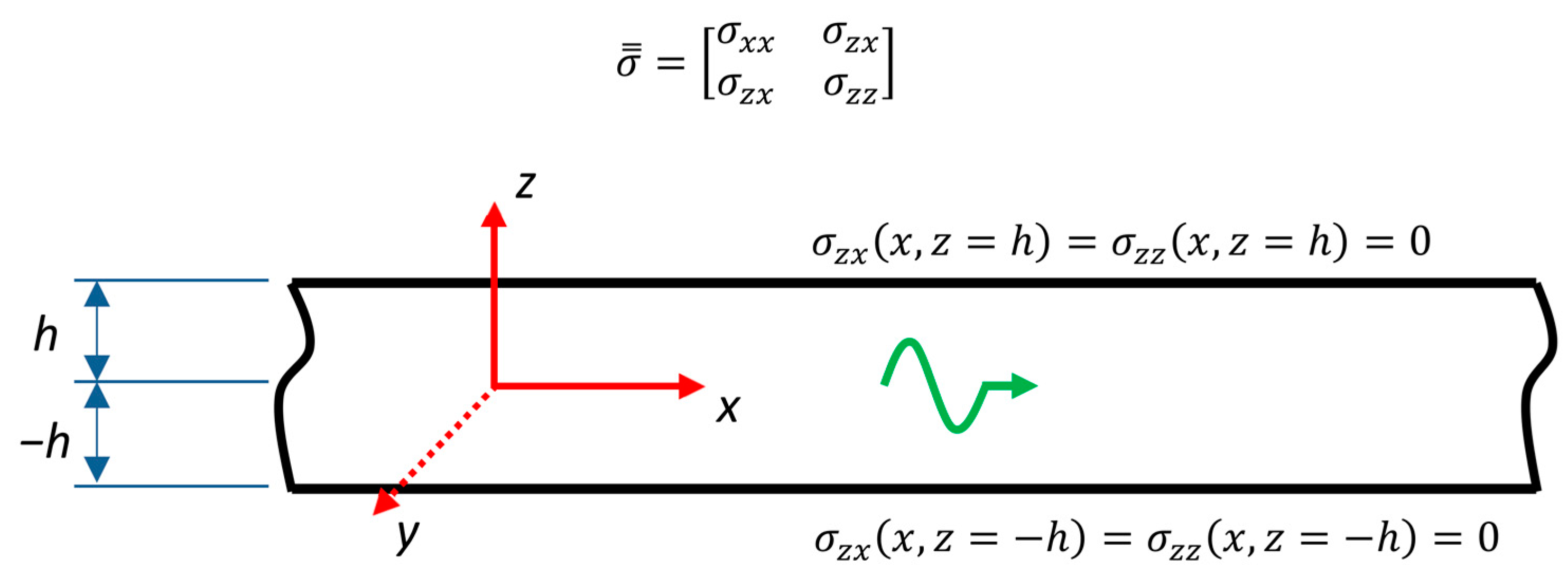
2.1. General Background

Let us now consider a waveguide of homogeneous thickness under the plane strain condition with stress-free boundaries (see Figure 1). By assuming the stress and displacement field time dependence in the form of e i ω t and, at the same time, using the constitutive equations:
σ i j = λ θ δ i j + 2 μ ε i j
the equation of motion can be presented:
× σ = = ρ u ¨
expressed purely in terms of the displacement vector u :
μ 2 u + ( λ + μ ) ( × u ) = ρ ω 2 u ,
where u ( x , z ) = { u , w } T , t refers to time,   δ i j is Kronecker delta,   θ denotes dilatation, ρ refers to density, ω is angular frequency, ε i j refers to the symmetrical strain tensor component, and σ i j represents component of the symmetrical stress tensor σ = :
σ = = [ σ x x σ z x σ z x σ z z ]
Using the Helmholtz decomposition theorem [41] and the given boundary conditions (see Figure 1), it is possible to derive the Rayleigh–Lamb dispersion equation, which is used to identify the real, complex, or pure imaginary wavenumbers for given material parameters and f t h product where t h is plate thickness and f refers to the frequency. The Lamb wave problem may be treated as an eigenvalue problem for wavenumber k under the assumption of separation of variables x and z in the displacement and stress field functions [24,25], which forming a discrete spectrum as the associated eigenfunctions:
[ u n ( x , z ) w n ( x , z ) σ x x n ( x , z ) σ z x n ( x , z ) ] = [ u ˜ n ( z ) w ˜ n ( z ) σ ˜ x x n ( z ) σ ˜ z x n ( z ) ] e i k n x
where subscript   . n denotes the n-th wavenumber k n , and subscript . ˜ expresses the functional dependence on the spatial coordinate   z . The already identified spectrum may be subsequently split into two parts [24], thus representing the wave propagation in opposite directions with respect to a given coordinate axis x. Assuming the completeness of Lamb wave mode, as proved by Kirrmann [42], the resulting stress/displacement field can be represented as a sum of individual stress/displacement components, which are weighted by complex amplitudes α n + / α n for the n-th mode with wavenumber k n :
[ u ( x , z ) w ( x , z ) σ x x ( x , z ) σ z x ( x , z ) ] = n [ m n ( x ) u ˜ n + ( z ) n n ( x ) w ˜ n + ( z ) n n ( x ) σ ˜ x x n + ( z ) m n ( x ) σ ˜ z x n + ( z ) ] = n α n + ( x ) [ u ˜ n + ( z ) w ˜ n + ( z ) σ ˜ x x n + ( z ) σ ˜ z x n + ( z ) ] + n α n ( x ) [ u ˜ n ( z ) w ˜ n ( z ) σ ˜ x x n ( z ) σ ˜ z x n ( z ) ]
where subscript . refers to left-moving waves and subscript . + refers to right-moving waves. Let us now introduce the biorthogonality relation [26]:
t h   u ˜ n ( z ) σ ˜ x x m ( z ) + w ˜ m ( z ) σ ˜ z x n ( z ) d z = Λ n δ m n ,
which, using vectors:
M n ( z ) = [ u ˜ n ( z ) σ ˜ z x n ( z ) ] , N n ( z ) = [ σ ˜ x x n ( z ) w ˜ n ( z ) ]
can be rewritten in the following form:
( M n | N m ) = Λ n δ m n ,
where   Λ n is a normalization factor, δ m n is the Kronecker delta symbol, t h refers to waveguide thickness [ h , h ] , and ( | ) defines the inner product. The total stress/displacement field with respect to Equation (8) can be defined in the following manner:
M ( x , z ) = [ u σ z x ] = n m n ( x )   M n ( z ) , N ( x , z ) = [ σ x x w ] = n n n ( x )   N n ( z ) ,
Using a systematic projection between individual vectors M , M n ,   N , N n , it is possible to identify the desired m n ,   n n variables [24]:
( M | N m ) = n m n ( x ) ( M n | N m ) = Λ m m m ( x ) , ( M m | N ) = n n n ( x ) ( M m | N n ) = Λ m n m ( x ) .
For further convenience, we use the power-normalized form of the individual eigenfunctions u ˜ n , w ˜ n ,   σ ˜ x x n , σ ˜ z x n , where the normalization is performed by the square root of the time-averaged acoustic power flow P x n [24,27]:
P x n = ω 2 | Λ n | .
Due to this step, the acoustic power flow for a given mode can be calculated as the square of the complex amplitude magnitude.

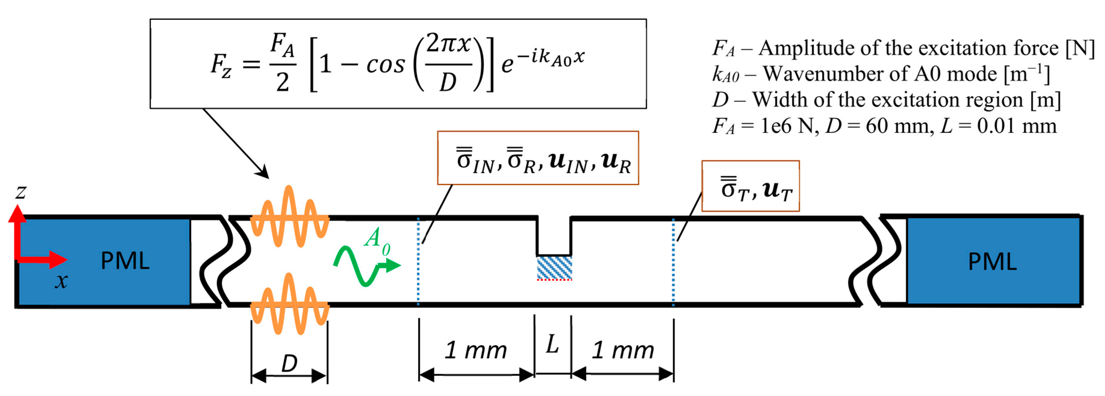
2.2. Scattering of Lamb Waves at Vertical Notch

Consider a homogeneous thickness waveguide with the present vertical notch of finite width L, as shown in Figure 2. Note that the section below the notch is additionally split into two sub-waveguides for further application of the PET approach. Each waveguide section is numbered (number in a circle), including its interface.
The continuity condition in terms of displacement vector/stress tensor components for a given interface is introduced by the following relations [27]:
M 1 ( x 1 , z ) = n = 1 N m 1 n ( x 1 ) M 1 n ( z ) = { M 2 ( x 1 , z ) = n = 1 N m 2 n ( x 1 ) M 2   n ( z ) , z t h 1 2 t h 2 , t h 1 2 M 3   ( x 1 , z ) = n = 1 N m 3   n ( x 1 ) M 3   n ( z ) , z t h 1 2 + t h 4 , t h 1 2 + t h 4 + t h 3 M 4   ( x 1 , z ) = n = 1 N m 4   n ( x 1 ) M 4   n ( z ) , z t h 1 2 , t h 1 2 + t h 4
N 1   ( x 1 , z ) = n = 1 N n 1   n ( x 1 ) N 1   n ( z ) = { N 2   ( x 1 , z ) = n = 1 N n 2   n ( x 1 ) N 2   n ( z ) , z t h 1 2 t h 2 , t h 1 2 N 3   ( x 1 , z ) = n = 1 N n 3   n ( x 1 ) N 3   n ( z ) , z t h 1 2 + t h 4 , t h 1 2 + t h 4 + t h 3 N 4   ( x 1 , z ) = n = 1 N n 4   n ( x 1 ) N 4   n ( z ) , z t h 1 2 , t h 1 2 + t h 4
Equations (13) and (14) can be further rewritten in the following form:
M 1   ( x 1 , z ) = n = 1 N m 1   n ( x 1 ) M 1   n ( z ) = m = 2 N w = 4 n = 1 N m m   n ( x 1 ) M m   n ( z ) ,  
N 1   ( x 1 , z ) = n = 1 N n 1   n ( x 1 ) N 1   n ( z ) = m = 2 N w = 4 n = 1 N n m   n ( x 1 ) N m   n ( z ) ,
where N refers to the number of considered Lamb wave modes for which N , N w represents the highest index number of sub-waveguide section present and associated with the main waveguide at the junction x = x 1 at the same time (see Figure 2), and the left subscript denotes the waveguide affiliation. Using the biorthogonality relation (Equation (7)) and the related systematic projections of the individual vectors M , M n ,   N , N n , it is possible to separate the m n ,   n n variables, which are affiliated to the main waveguide (section number 1—see Figure 2):
( M 1   | N 1   w ) | t h 1   = ( M 2   | N 1   w ) | t h 2   + ( M 3   | N 1   w ) | t h 3   + ( M 4   | N 1   w ) | t h 4   = m 1   w Λ 1   w ,
( M 1   n | N 1   ) | t h 1   = ( M 1   n | N 2   ) | t h 2   + ( M 1   n | N 3   ) | t h 3   + ( M 1   n | N 4   ) | t h 4   = n 1   n Λ 1   n ,
and for the present sub-waveguides denoted by section numbers 2–4 (see Figure 2):
( M 1 | N m   n ) | t h m   = w = 1 N m 1   w ( M 1   w | N m   n ) | t h m   = m n m Λ n m ,
( M m   w | N 1   ) | t h m   = n = 1 N n 1   n ( M m   w | N 1   n ) | t h m   = n w m Λ w m ,
where | t h m   denotes the integration over the specified sub-waveguide thickness in the form of the given inner product. After the rearrangement of Equations (17)–(20) [43,44], we can derive the explicit formulation of the global scattering matrix, a linear operator, which links the vectors containing the complex amplitudes of the reflected waves v R = [ α 1 ( x 1 ) α + 1 ( x 2 ) ] T with the vector containing the complex amplitudes of the incident ones— v I N = [ α + 1 ( x 1 ) α 1 ( x 2 ) ] T :
[ α 1 ( x 1 ) α + 1 ( x 2 ) ] = S 1       ( x 1 , x 2 ) [ α + 1 ( x 1 ) α 1 ( x 2 ) ] ,
where:
S   1     ( x 1 , x 2 ) = { M 1 1 m = 2 N w = 3   M 2 m + M 3 m } 1 { m = 2 N w = 3   M 4 m + M 5 m } ,
with [43]:
M 1 1 = [ 2 Λ 1   [ 0 ] N x N [ 0 ] N x N 2 Λ 1   ]
M 2 m = [ H 1 , m     [ 0 ] N x N [ 0 ] N x N H 1 , m     ] [ R + m ( x 1 ) T m ( x 2 , x 1 ) T + m ( x 1 , x 2 ) R + m ( x 2 ) ] [ 2 m Λ [ 0 ] N x N [ 0 ] N x N 2 m Λ ] 1 [ K 1 , m     [ 0 ] N x N [ 0 ] N x N K 1 , m     ] ,
M 3 m = [ G 1 , m     [ 0 ] N x N [ 0 ] N x N G 1 , m     ] [ 2 Λ m   [ 0 ] N x N [ 0 ] N x N 2 Λ m   ] 1 [ K 1 , m     [ 0 ] N x N [ 0 ] N x N K 1 , m     ] ,
M 4 m = [ H 1 , m [ 0 ] N x N [ 0 ] N x N H 1 , m ] [ R + m ( x 1 ) T m ( x 2 , x 1 ) T + m ( x 1 , x 2 ) R + m ( x 2 ) ] [ 2 m Λ [ 0 ] N x N [ 0 ] N x N 2 m Λ ] 1 [ J 1 , m [ 0 ] N x N [ 0 ] N x N J 1 , m ] ,
M 5 m = [ G 1 , m     [ 0 ] N x N [ 0 ] N x N G 1 , m     ] [ 2 Λ m   [ 0 ] N x N [ 0 ] N x N 2 Λ m   ] 1 [ J 1 , m     [ 0 ] N x N [ 0 ] N x N J 1 , m     ] ,
G 1 , m   ( n , w ) = ( M 1   n | N m   w ) | t h m   ( M m   n | N 1   w ) | t h m   ,  
H 1 , m   ( n , w ) = ( M 1   n | N m   w ) | t h m   + ( M m   n | N 1   w ) | t h m   ,
J 1 , m   ( n , w ) = ( M 1   w | N m   n ) | t h m   + ( M m   w | N 1   n ) | t h m   ,  
K 1 , m   ( n , w ) = ( M m   w | N 1   n ) | t h m   ( M 1   w | N m   n ) | t h m   .
where R m   + ( x 1 ) represents the reflection matrix affiliated to the m-th waveguide and, at the same time, containing the complex amplitudes of left-moving reflected waves at interface x = x1, R m   + ( x 2 ) refers to reflection matrix containing the complex amplitudes of right-moving reflected waves at interface x = x2, T m   +   ( x 1 , x 2 ) represents the transmission matrix containing the complex amplitudes of right-moving waves transmitted through the waveguide section defined by coordinates x 1 , x 2 and T m     ( x 2 , x 1 ) refers to a transmission matrix containing the complex amplitudes of left-moving waves transmitted through the waveguide section defined by coordinates x 2 , x 1 (see Figure 2). The local scattering matrices for sub-waveguides 2–4 are defined in the following way:
S m ( x 1 , x 2 ) = [ R + m ( x 1 ) T m     ( x 2 , x 1 ) T m   +   ( x 1 , x 2 ) R + m ( x 2 ) ] .
In the case of sub-waveguide 2, the following applies:
S 2 ( x 1 , x 2 ) = [ R + 2 ( x 1 ) [ 0 ] N x N [ 0 ] N x N R + 2 ( x 2 ) ] ,
where, due to the symmetry of the vertical notch with respect to the axis y, the reflection matrices R + 2 ( x 1 ) and R + 2 R + ( x 2 ) are identical. The resulting expression of the scattering matrix is as follows [27]:
R + m   ( x 1 ) = R + m   ( x 2 ) = ( L + V T 2 Λ ) 1 ( V T L ) ,
with:
V ( n , w ) = ( u ˜ n | σ ˜ x x w ) | z = z 1 z = z 2 ,
L ( n , w ) = ( σ ˜ z x n | w ˜ w ) | z = z 1 z = z 2 ,
u / σ denotes a vector form of a given displacement vector/stress tensor component and z1/z2 refers to the given integration limits. The local scattering matrices of sub-waveguides 3 and 4 will be in following form:
S m   ( x 1 , x 2 ) = [ [ 0 ] N x N d i a g ( e i   k     n | x | ) d i a g ( e i   k     n | x | ) [ 0 ] N x N ] ,   m = 3 ,   4
It has to be noted that the global scattering matrix including its accompanying computations has a semi-analytical characteristic, in which the scalar products are determined analytically, whereas the inverse matrix operations are realized using a numerical procedure.
Let us now return to Figure 2, where the PET technique is applied to sub-waveguide section No. 3. The modification concerns matrices G 1 , 3   ,   H 1 , 3   ,   J 1 , 3     ,   K 1 , 3   and subsequently also matrices M   3   2 ÷ M   3   2 , where the eigenfunctions N 3   w / M 3   n / M 3   w / N 3   n are assembled according to the modified value of Young´s modulus to provide the desired ratio of transmitted/reflected energy through the considered section. The identification of the required value of Young´s modulus can be performed either using the PET approach or by utilizing FEM analysis in combination with an appropriate postprocessing tool.

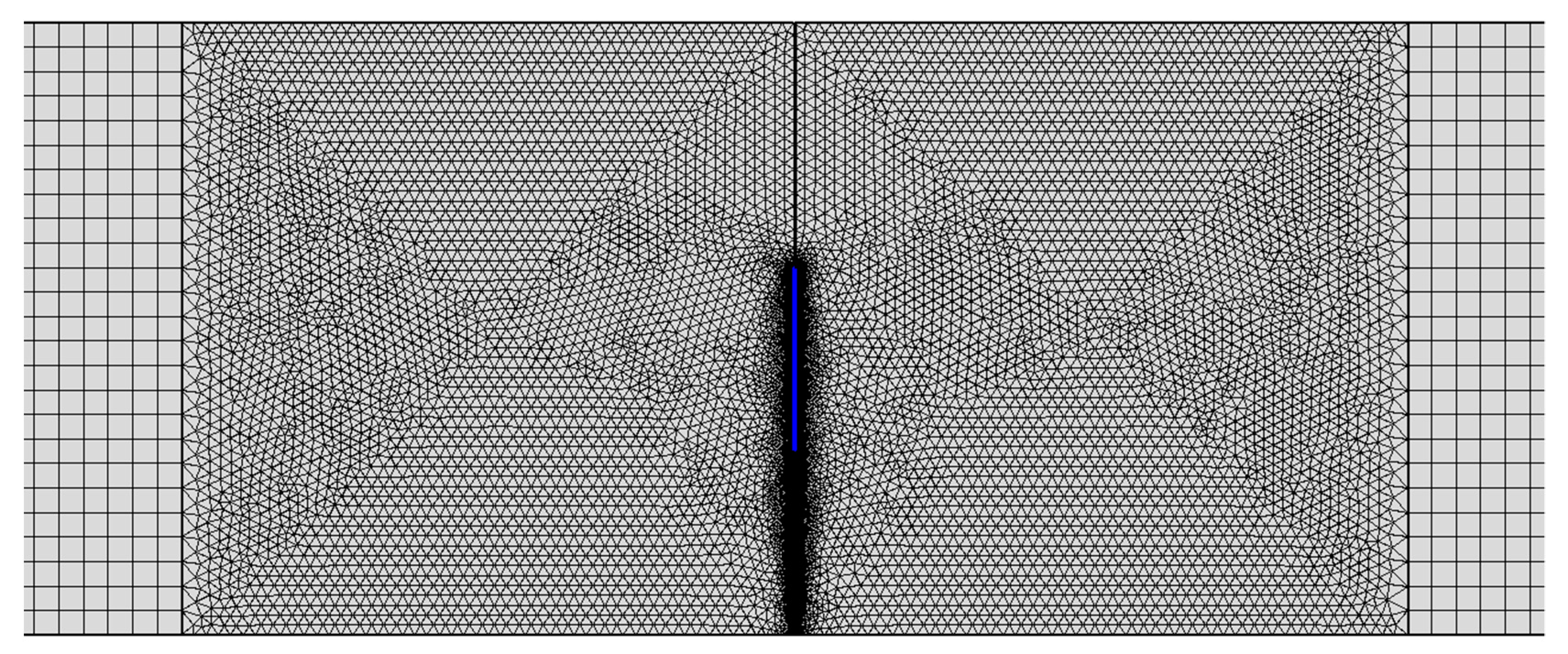
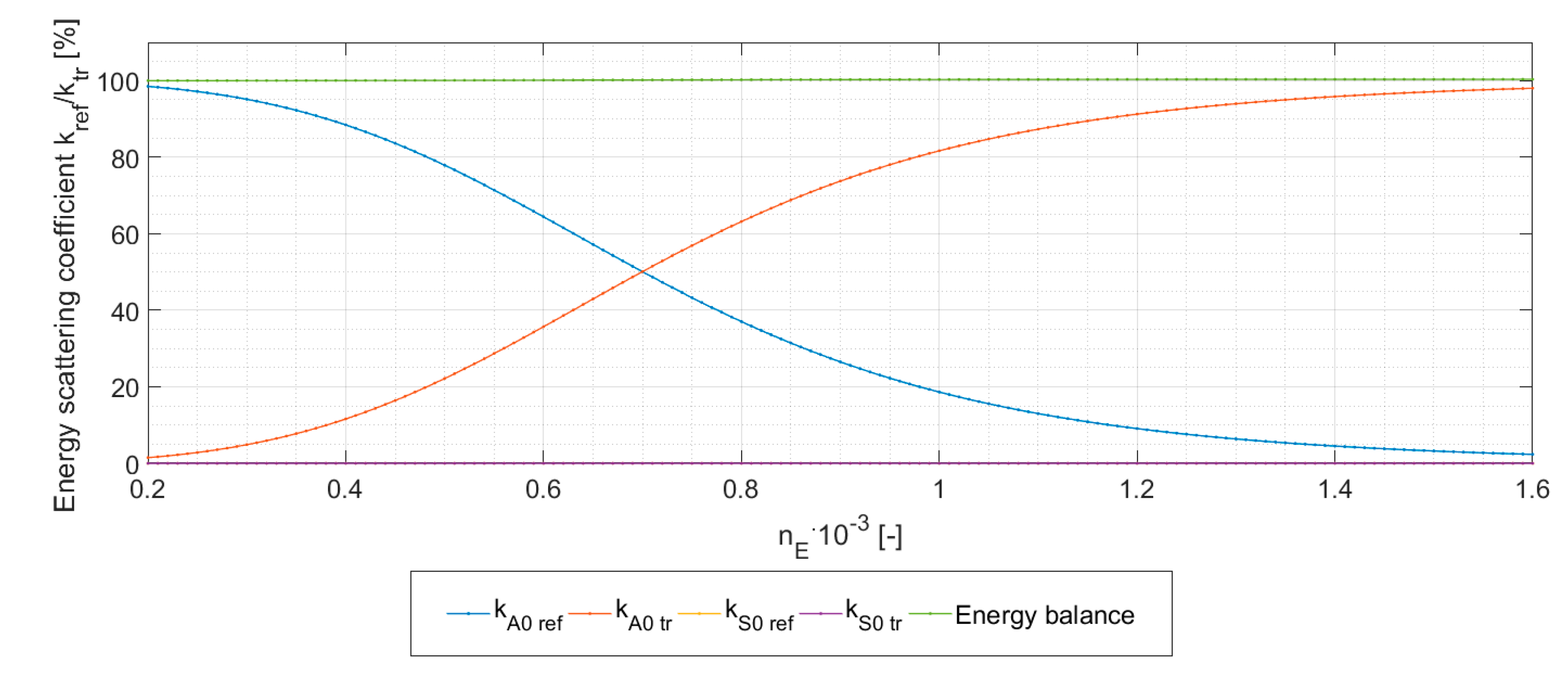
3. Numerical Verification of PET Model

The PET approach is verified based on an application example, for which the geometry is presented in Figure 2, where the partial energy transfer functionality is applied to sub-waveguide No. 3. The incident mode is in the form of a fundamental antisymmetric Lamb wave (A0) of central frequency equal to 150 kHz. The selection of the incident mode in the form of the A0 Lamb wave mode was realized purely from a practical point of view, because it has versatile use in real applications. The overall thickness of the aluminum plate (ρ = 2660 kg/m3, c L = 6295 m/s, c T = 3100 m/s → Young´s modulus E = 68.5 GPa, Poisson´s ratio ν = 0.34 [-]) was 10 mm, and the thickness of waveguides 2–4 was equal to 4,3 and 3 mm, respectively, and width L equal to 0.01 mm.
The reference values of the energy scattering coefficients were obtained in the same manner as in [43], i.e., by utilizing the hybrid approach, which combines FEM with the general orthogonality relation. Using the FEM, it is possible to extract the through-thickness stress tensor and displacement vector components of the incident (subscript IN), reflected (subscript R), and transmitted (subscript T) modes at a given distance from the discontinuity (see Figure 3), namely one millimeter.
The FEM simulations were realized in COMSOL Multiphysics software in frequency domain. The scattering region and its close vicinity were meshed using linear triangular elements with a maximum allowable size of 0.2 mm, whereas the remainder of the geometry, including the perfectly matched layer (PML), which served to eliminate the undesired reflections, was meshed using linear rectangular elements with a size of 0.4 mm (see Figure 4).
The excitation of the incident A0 mode was utilized with Hanning-windowed toneburst in the form of normal force, which was applied on opposite surfaces. It should be noted that the applied excitation on given boundaries is antisymmetric with respect to the mid-plane axis.
Once the desired through-thickness variables for the incident, reflected, and scattered mode are identified, it is possible to calculate the energy scattering coefficients, which due to the power-normalization of stress/displacement components, can be expressed using complex amplitudes [16,43]:
k R n = P A V   R n P A V   I N = | α n   R | 2 | α I N | 2 = 0 t h ( σ ˜ x   R n   u R F E M + σ x   R F E M u ˜ R n τ ˜ x z   R n v R F E M τ x z   R F E M v ˜ R n )   d z × { 2 0 t h [ σ ˜ x   R n u ˜ R n   τ ˜ x z   R n v ˜ R n ] d z } 1 0 t h ( σ ˜ x   I N   u I N F E M + σ x   I N F E M u ˜ I N   τ ˜ x z   I N     v I N F E M τ x z   I N F E M v ˜ I N   )   d z × { 2 0 t h [ σ ˜ x   I N   u ˜ I N       τ ˜ x z   I N   v ˜ I N   ] d z } 1 ,
k T n = P A V   T n P A V   I N = | α n   T | 2 | α I N | 2 = 0 t h ( σ ˜ x   T n u T F E M + σ x   T F E M u ˜ T n τ ˜ x z   T n v T F E M τ x z   T F E M v ˜ T n )   d z × { 2 0 t h [ σ ˜ x   T n u ˜ T n τ ˜ x z   T n v ˜ T n ] d z } 1 0 t h ( σ ˜ x   I N   u I N F E M + σ x   I N F E M u ˜ I N   τ ˜ x z   I N     v I N F E M τ x z   I N F E M v ˜ I N   )   d z × { 2 0 t h [ σ ˜ x   I N   u ˜ I N     τ ˜ x z   I N   v ˜ I N   ] d z } 1 ,
where P A V   I N   / P A V   R n / P A V   T n express time-averaged acoustic power flow of incident/reflected/transmitted modes, k R   / k T   are energy scattering coefficients of reflected/transmitted modes, α I N / α R / α T are complex amplitudes of incident/reflected/transmitted modes, the superscript F E M denotes the total stress/displacement field obtained by FEM computation, the subscript/superscript n denotes the n-th considered Lamb wave mode and the subscripts I N / R / T in the case of displacement/stress components represent affiliation to incident/reflected/transmitted modes. As stated above, the PET approach was applied to sub-waveguide 3 (interfaces 3,6—see Figure 2), where, due to the fact that the incident mode is antisymmetric (A0), the amount of transmitted/reflected energy in the concerned sub-waveguide is related to the power of the A0 mode in this waveguide.
The identification of the desired value of Young´s modulus, which induces the given ratio between transmitted and reflected energy for A0 mode in sub-waveguide 3, was performed using the hybrid approach presented above. Figure 5 displays the dependence of energy scattering coefficients for the reflected and transmitted A0/S0 waves versus the multiplier of Young´s modulus nE for sub-waveguide 3. It should be noted that the given values were also used by the semi-analytical model incorporating the PET approach. In the next step, both methods, i.e., semi-analytical and hybrid approaches, were then used to evaluate the energy scattering coefficients for selected fractions of reflected or transmitted energy of A0 mode in sub-waveguide 3. In the case of the semi-analytical approach, the analysis began with the identification of real, imaginary, and complex wavenumbers [45], including an additional refinement procedure based on the Newton–Raphson method, in which the complex wavenumbers have to be considered in the form of conjugate pairs [44].
Feng et al. [46] proved that the best results are obtained when the number of wavenumbers corresponding to S modes NS is higher by one compared to the number of A modes NA, i.e., NS = NA + 1. For the total number N of considered wavenumbers, therefore, N = NA + NS = 2NA + 1 must apply. In the initial step, a wave vector is formed by real, imaginary, and one pair of complex wavenumbers, whereas the energy scattering coefficients including the energy balance are evaluated. Each subsequent iteration is characterized by the increase in the complex wavenumber conjugate pair by one, with subsequent computation of the scattering coefficients and the related energy balance. This process is repeated until a permissible value of the energy balance is obtained.

4. Results and Conclusions

The energy scattering coefficients affiliated with the main waveguide Section 1 (see Figure 2) were calculated using both techniques, i.e., PET model and hybrid method, for the following percentages of the reflected energy in the sub-waveguide 3: 0, 2.3, 4.7, 10, 20, 30, 40, 50, 60, 70, 80, 92, and 99. For each computational process within the predefined percentage of the reflected energy value in the given sub-waveguide, we followed the procedure described in Section 3. The optimal total number of wavenumbers for a given configuration in the case of the PET model was identified using the minimalization of the self-proposed error function:
e r r o r N i = 0.2 × ( | k A 0 r e f F E M k A 0 r e f P E T k A 0 r e f F E M | + | k S 0 r e f F E M k S 0 r e f P E T k S 0 r e f F E M | + | k A 0 t r F E M k A 0 t r P E T k A 0 t r F E M | + | k S 0 t r F E M k S 0 t r P E T k S 0 t r F E M | ) + 0.8 × | 100 E B P E T 100 | + ( 0.1 N i N i n i t i a l ) 1 3 ,
where e r r o r N i   refers to the error value for Ni considered wavenumbers, k r e f F E M / k t r F E M / k r e f P E T / k t r P E T denote the energy reflection coefficients of reflected/transmitted modes obtained using the FEM/PET approach, N i n i t i a l refers to the initial total number of wavenumbers, and N i denotes the total number of wavenumbers for the i-th iteration. It should be noted that the hybrid approach (denoted by the “FEM” superscript) provides a reference to the PET model, which is obvious from Equation (36), where the individual error contributions of the PET model energy scattering coefficients are related to their FEM model counterparts. Moreover, the error formulae also use weighted functions, which have to emphasize the result from the energy balance criterion. The last term in Equation (36) is used to benefit the results with a lower considered number of wavenumbers and, at the same time, with an acceptable energy balance condition.
Figure 6 displays the relationship between the energy scattering coefficients of A0/S0 modes affiliated to the main waveguide Section 1 (see Figure 2), which were obtained by both presented methods. It is obvious that the PET approach shows very good, if not excellent, agreement compared to its FEM counterpart, where the maximum difference between the reference values of the scattering coefficients was not greater than 4% across the entire range of the percentage of reflected energy in sub-waveguide 3.
The convergence characteristic of the semi-analytical method incorporating the PET approach was primarily influenced by the utilized value of the percentage of reflected energy in sub-waveguide 3. From Figure 7, it can be seen that the higher the percentage of reflected energy in the given sub-waveguide, the larger the number of real and pure imaginary wavenumbers in the given section. This behavior has a direct effect on the modified value of Young’s modulus, which needs to be accordingly reduced by the multiplier nE. By comparison, the optimal value of the total number of wavenumbers, which ensures the best energy balance, has only a slightly increasing trend and tends to occur between 20 and 50. Additionally, the convergence effectiveness across the entire interval of percentages of reflected energy is clearly demonstrated by the graphs presented in Figure 8, Figure 9 and Figure 10. An interesting finding was that rapid increase in the real/imaginary wavenumbers in sub-waveguide Section 3 compared to the other sections did not negatively influence the convergence characteristic, and even forced the value of the optimal number of wavenumbers toward the initial point—see Figure 10.
In conclusion, it should be noted that the entire computational process using the PET approach showed very good numerical stability across the entire range of the considered values of the percentage of reflected energy in the given sub-waveguide, even when the material properties resulting from the prescribed value of Young’s modulus, which maintained the energy flow through the waveguide, were physically implausible. In the future, we would like to use this approach to address more complex issues in the form of an angled surface breaking crack exhibiting multipoint contact of the fracture surfaces.

Author Contributions

P.Š. and M.Š. wrote the manuscript. M.R. performed the numerical analysis. D.C. and P.K. reviewed the manuscript. All authors have read and agreed to the published version of the manuscript.

Funding

This work was supported by the project Innovative and additive manufacturing technology—new technological solutions for 3D printing of metals and composite materials—CZ.02.1.01/0.0/0.0/17_049/0008407 and by the project No. 8JPL19022. This work was also supported by the European Regional Development Fund in the Research Centre of Advanced Mechatronic Systems project, CZ.02.1.01/0.0/0.0/16_019/0000867 within the Operational Programme Research, Development and Education and the project SP2021/27 Advanced methods and technologies in the field of machine and process control supported by the Ministry of Education, Youth and Sports, Czech Republic.

Institutional Review Board Statement

Not applicable.

Informed Consent Statement

Not applicable.

Data Availability Statement

Data can be provided upon request from the correspondent author.

Conflicts of Interest

The authors declare no conflict of interest.

References

  1. Park, S.-J.; Kim, H.-W.; Joo, Y.-S. Leaky Lamb Wave Radiation from a Waveguide Plate with Finite Width. Appl. Sci. 2020, 10, 8104. [Google Scholar] [CrossRef]
  2. DiBiase, M.; De Marchi, L. Clusters of Shaped Ultrasonic Transducers for Lamb Waves’ DoA Estimation. Appl. Sci. 2020, 10, 8150. [Google Scholar] [CrossRef]
  3. Stobbe, D.M.; Grünsteidl, C.M.; Murray, T.W. Propagation and scattering of Lamb waves at conical points in plates. Sci. Rep. 2019, 9, 15216. [Google Scholar] [CrossRef] [PubMed] [Green Version]
  4. Andhale, Y.S.; Masurkar, F.; Yelve, N.P. Localization of Damages in Plain And Riveted Aluminium Specimens using Lamb Waves. Int. J. Acoust. Vib. 2019, 24, 150–165. [Google Scholar] [CrossRef]
  5. Mori, N.; Biwa, S. Transmission of Lamb waves and resonance at an adhesive butt joint of plates. Ultrasonics 2016, 72, 80–88. [Google Scholar] [CrossRef] [Green Version]
  6. Eremin, A.; Golub, M.; Glushkov, E.; Glushkova, N. Identification of delamination based on the Lamb wave scattering resonance frequencies. Ndt E Int. 2019, 103, 145–153. [Google Scholar] [CrossRef]
  7. Glushkov, E.; Glushkova, N.; Eremin, A.; Lammering, R. Trapped mode effects in notched plate-like structures. J. Sound Vib. 2015, 358, 142–151. [Google Scholar] [CrossRef]
  8. Mori, N.; Kusaka, T. Reflection and transmission characteristics of Lamb waves at an adhesive lap joint of plates. J. Acoust. Soc. Am. 2019, 145, 3075–3085. [Google Scholar] [CrossRef]
  9. Glushkov, E.; Glushkova, N.; Eremin, A.; Giurgiutiu, V. Low-cost simulation of guided wave propagation in notched plate-like structures. J. Sound Vib. 2015, 352, 80–91. [Google Scholar] [CrossRef]
  10. Glushkov, E.; Glushkova, N.; Golub, M.; Eremin, A. Resonance blocking and passing effects in two-dimensional elastic waveguides with obstacles. J. Acoust. Soc. Am. 2011, 130, 113–121. [Google Scholar] [CrossRef] [Green Version]
  11. Golub, M.; Shpak, A.; Mueller, I.; Fomenko, S.; Fritzen, C.-P. Lamb Wave Scattering Analysis for Interface Damage Detection between a Surface-Mounted Block and Elastic Plate. Sensors 2021, 21, 860. [Google Scholar] [CrossRef]
  12. Koshiba, M.; Morita, H.; Suzuki, M. Finite-element analysis of discontinuity problem of SH modes in an elastic plate waveguide. Electron. Lett. 1981, 17, 480–482. [Google Scholar] [CrossRef]
  13. Koshiba, M.; Karakida, S.; Suzuki, M. Finite-Element Analysis of Lamb Wave Scattering in an Elastic Plate Waveguide. IEEE Trans. Sonics Ultrason. 1984, 31, 18–24. [Google Scholar] [CrossRef] [Green Version]
  14. Moser, F.; Jacobs, L.J.; Qu, J. Modeling elastic wave propagation in waveguides with the finite element method. Ndt E Int. 1999, 32, 225–234. [Google Scholar] [CrossRef]
  15. Cho, Y.; Rose, J.L. An elastodynami’c hybrid boundary element study for elastic guided wave interactions with a surface breaking defect. Int. J. Solids Struct. 2000, 37, 4103–4124. [Google Scholar] [CrossRef]
  16. Moreau, L.; Castaings, M.; Hosten, B.; Predoi, M.V. An orthogonality relation-based technique for post-processing finite element predictions of waves scattering in solid waveguides. J. Acoust. Soc. Am. 2006, 120, 611–620. [Google Scholar] [CrossRef]
  17. Gunawan, A.; Hirose, S. Mode-exciting method for Lamb wave-scattering analysis. J. Acoust. Soc. Am. 2004, 115, 996–1005. [Google Scholar] [CrossRef]
  18. Hakoda, C.; Lissenden, C.J. Using the Partial Wave Method for Wave Structure Calculation and the Conceptual Interpretation of Elastodynamic Guided Waves. Appl. Sci. 2018, 8, 966. [Google Scholar] [CrossRef] [Green Version]
  19. Torvik, P.J. Reflection of Wave Trains in Semi-Infinite Plates. J. Acoust. Soc. Am. 1967, 41, 346–353. [Google Scholar] [CrossRef]
  20. Gregory, R.D.; Gladwell, I. The reflection of a symmetric Rayleigh-Lamb wave at the fixed or free edge of a plate. J. Elast. 1983, 13, 185–206. [Google Scholar] [CrossRef]
  21. Grahn, T. Lamb wave scattering from a circular partly through-thickness hole in a plate. Wave Motion 2003, 37, 63–80. [Google Scholar] [CrossRef]
  22. Moreau, L.; Caleap, M.; Velichko, A.; Wilcox, P. Scattering of guided waves by through-thickness cavities with irregular shapes. Wave Motion 2011, 48, 586–602. [Google Scholar] [CrossRef]
  23. Shkerdin, G.; Glorieux, C. Lamb mode conversion in a plate with a delamination. J. Acoust. Soc. Am. 2004, 116, 2089–2100. [Google Scholar] [CrossRef]
  24. Pagneux, V.; Maurel, A. Lamb wave propagation in inhomogeneous elastic waveguides. Proc. R. Soc. Lond. A 2002, 458, 1913–1930. [Google Scholar] [CrossRef]
  25. Pagneux, V.; Maurel, A. Lamb wave propagation in elastic waveguides with variable thickness. Proc. R. Soc. Lond. A 2006, 462, 1315–1339. [Google Scholar] [CrossRef]
  26. Fraser, W.B. Orthogonality relation for the Rayleigh–Lamb modes of vibration of a plate. J. Acoust. Soc. Am. 1976, 59, 215–216. [Google Scholar] [CrossRef]
  27. Feng, F.; Shen, J.; Lin, S. Scattering matrices of Lamb waves at irregular surface and void defects. Ultrasonics 2012, 52, 760–766. [Google Scholar] [CrossRef] [PubMed]
  28. Feng, F.; Lin, S. The band gaps of Lamb waves in a ribbed plate: A semi-analytical calculation approach. J. Sound Vib. 2014, 333, 124–131. [Google Scholar] [CrossRef]
  29. Feng, F.L.; Shen, J.Z.; Deng, J.J.; Wang, Q.P. Analytical Solution of Lamb Wave Scattering at Plate End. Adv. Mater. Res. 2011, 199–200, 949–952. [Google Scholar] [CrossRef]
  30. Feng, F.; Shen, J.; Deng, J. The scattering matrices of Lamb waves at multiple delaminations and broken laminates. Ndt E Int. 2012, 49, 64–70. [Google Scholar] [CrossRef]
  31. Trofimov, A.; Drach, B.; Kachanov, M.; Sevostianov, I. Effect of a partial contact between the crack faces on its contribution to overall material compliance and rezistivity. Int. J. Solids Struct. 2016, 108, 289–297. [Google Scholar] [CrossRef]
  32. Beghini, M.; Bertini, L.; Fontanari, V. A weight function technique for partially closed inclined edge cracks analysis. Int. J. Fract. 2001, 112, 57–68. [Google Scholar] [CrossRef]
  33. Zhao, J.; Liu, R.; Wu, X. Effects of partial crack-face contact for the bending of thin shell structures. Appl. Fract. Mech. 2008, 49, 128–150. [Google Scholar] [CrossRef]
  34. Bowles, S.J.; Harding, C.A.; Hugo, G.R. Effect of Crack Closure on Ultrasonic Detection of Fatigue Cracks at Fastener Holes. AIP Conf. Proc. 2009, 1096, 1878–1885. [Google Scholar]
  35. Thompson, R.B.; Skillings, B.J.; Zachary, L.W.; Schmerr, L.W.; Buck, O. Effects of Crack Closure on Ultrasonic Transmission. Rev. Prog. Quant. Nondestruct. Eval. 1983, 2A, 325–343. [Google Scholar] [CrossRef] [Green Version]
  36. Thompson, R.B.; Fiedler, C.J. The Effects of Crack Closure on Ultrasonic Scattering Measurements. In Review of Progress in Quantitative Nondestructive Evaluation; Metzler, J.B., Ed.; Springer: Boston, MA, USA, 1984; pp. 207–215. [Google Scholar]
  37. Matsushita, M.; Mori, N.; Biwa, S. Transmission of Lamb waves across a partially closed crack: Numerical analysis and experiment. Ultrasonics 2019, 92, 57–67. [Google Scholar] [CrossRef]
  38. An, Y.-K. Measurement of crack-induced non-propagating Lamb wave modes under varying crack widths. Int. J. Solids Struct. 2015, 62, 134–143. [Google Scholar] [CrossRef]
  39. Lee, B.C.; Staszewski, W.J. Modelling of Lamb wave interaction with open and closed fatigue cracks for damage detection. Iop Conf. Ser. Mater. Sci. Eng. 2010, 10, 1–10. [Google Scholar] [CrossRef]
  40. Yamanaka, K.; Mihara, T.; Tsuji, T. Evaluation of Closed Cracks by Model Analysis of Subharmonic Ultrasound. Jpn. J. Appl. Phys. 2004, 43, 3082–3087. [Google Scholar] [CrossRef]
  41. Achenbach, J.D. Reciprocity in Elastodynamics, Cambridge Monographs on Mechanics; Cambridge University Press: New York, NY, USA, 2004. [Google Scholar]
  42. Kirrmann, P. On the completeness of Lamb modes. J. Elast. 1995, 37, 39–69. [Google Scholar] [CrossRef]
  43. Šofer, M. Resonance phenomena of lamb waves scattering by a horizontal crack of finite length. J. Sound Vib. 2021, 490, 115742. [Google Scholar] [CrossRef]
  44. Šofer, M.; Šofer, P.; Ferfecki, P.; Molčan, M.; Stryja, J. Lamb wave mode scattering analysis on adhesively bonded single lap joint using modal decomposition method. Appl. Math. Model. 2021, 89, 413–427. [Google Scholar] [CrossRef]
  45. Šofer, M.; Ferfecki, P.; Šofer, P. Numerical solution of Rayleigh-Lamb frequency equation for real, imaginary and complex wavenumbers. In MATEC Web of Conferences; EDP Sciences: Les Ulis, France, 2018; Volume 157, p. 08011. [Google Scholar] [CrossRef] [Green Version]
  46. Feng, F.; Shen, Z.; Shen, J. Scattering of obliquely incident waves by straight features in a plate. Wave Motion 2016, 60, 84–94. [Google Scholar] [CrossRef]
Figure 1. Geometry of the Lamb wave problem.
Applsci 11 04508 g001
Figure 2. Scattering of Lamb wave at the vertical notch of width L.
Applsci 11 04508 g002
Figure 3. Scattering of Lamb wave at the vertical notch of width L—application of hybrid method.
Applsci 11 04508 g003
Figure 4. Discretization of the scattering region including its close vicinity; the region where the PET approach was adopted is marked by blue color.
Applsci 11 04508 g004
Figure 5. Energy scattering coefficients versus multiplier of Young´s modulus nE for sub-waveguide 3.
Applsci 11 04508 g005
Figure 6. Energy scattering coefficients in the main waveguide section versus percentage of reflected energy prescribed in sub-waveguide 3.
Applsci 11 04508 g006
Figure 7. Number of real/pure imaginary wavenumbers in sub-waveguide 3 versus the percentage of reflected energy prescribed in the considered sub-waveguide.
Applsci 11 04508 g007
Figure 8. Numerical convergence of energy scattering coefficients in waveguide 1 (2.3% of reflected energy in sub-waveguide 3).
Applsci 11 04508 g008
Figure 9. Numerical convergence of energy scattering coefficients in waveguide 1 (98.2% of reflected energy in sub-waveguide 3).
Applsci 11 04508 g009
Figure 10. Numerical convergence of energy scattering coefficients in waveguide 1 (99% of reflected energy in sub-waveguide 3).
Applsci 11 04508 g010
Publisher’s Note: MDPI stays neutral with regard to jurisdictional claims in published maps and institutional affiliations.

