Article

Prediction of Neural Space Narrowing and Soft Tissue Injury of the Cervical Spine Concerning Head Restraint Arrangements in Traffic Collisions

Department of Mechanical and Industrial Engineering, College of Engineering, Qatar University, Doha 2713, Qatar
*
Authors to whom correspondence should be addressed.
Appl. Sci. 2021, 11(1), 145; https://doi.org/10.3390/app11010145
Submission received: 14 November 2020 / Revised: 9 December 2020 / Accepted: 14 December 2020 / Published: 25 December 2020
(This article belongs to the Section Applied Biosciences and Bioengineering)

Abstract

:
Common quantitative assessments of neck injury criteria do not predict anatomical neck injuries and lack direct relations to design parameters of whiplash-protection systems. This study aims to provide insights into potential soft tissue-level injury sites based on the interactions developed in-between different anatomical structures in case of a rear-end collision. A detailed finite element human model has exhibited an excellent biofidelity when validated against volunteer impacts. Three head restraint arrangements were simulated, predicting both the kinematic response and the anatomical pain source at each arrangement. Head restraint’s contribution has reduced neck shear and head kinematics by at least 70 percent, minimized pressure gradients acting on ganglia and nerve roots less than half. Posterior column ligaments were the most load-bearing components, followed by the lower intervertebral discs and upper capsular ligaments. Sprain of the interspinous ligamentum flavum at early stages has caused instability in the craniovertebral structure causing its discs and facet joints to be elevated compressive loads. Excessive hyperextension motion, which occurred in the absence of the head restraint, has promoted a stable avulsion teardrop fracture of the fourth vertebral body’s anteroinferior aspect and rupture the anterior longitudinal ligament. The observed neck injuries can be mathematically related to head–torso relative kinematics. These relations will lead to the development of a comprehensive neck injury criterion that can predict the injury level. This, in turn, will impose a significant impact on the design processes of vehicle anti-whiplash safety equipment.

1. Introduction

The cervical spine is among the most vulnerable road injuries with a high risk of morbidity [1]. Whiplash trauma is a neck injury due to forceful, rapid back-and-forth movement of the neck that is often associated with rear-end traffic collisions. The reported annual treatment costs in the United States are as high as $5.2 billion [1]. In 2013, the United Kingdom announced that 76% of the insurance claims were associated with whiplash injuries, compared to an average of 48% throughout the rest of Europe [2]. Around 80.9% of patients had a mild neck injury following a traffic accident, and 19.1% had severe health complications [3]. Out of those, soft tissue injuries were the leading source of pain (16.2%), followed by disabilities due to spinal cord trauma (3.8%) and fracture-dislocations (1.3%). The key to reducing the whiplash’s motion is by minimizing the relative kinematics between the occupant’s head and torso. The primary countermeasure is the head restraints equipped in the vehicle to limit the neck’s hyperextension motion relative to the torso. However, their effectiveness is highly influenced by their position relative to the occupant’s head. Unfortunately, passengers rarely adjust their head restraint to the recommended position due to low public awareness [4]. Trempel and Edward [5] have reported a reduction of 11.2% in neck injuries for head restraints with good rating to poorly rated head restraints according to Insurance Institute for Highway Safety (IIHS). They have analyzed data from 36 insurance companies over 17 US states for 1754 vehicles between 2001–2014 models, and the claims were added up to 603,755 caused by rear-end collisions.
Traffic accident patients often have persistent chronic complaints due to whiplash, as addressed by several clinical reports [6]. Their findings suggested that the central nervous system’s hyperexcitability, which might start three to six months after the initial injury, seems to play the primary role in sustaining those pain complaints [6]. Nevertheless, the underlying anatomical pain mechanisms are still vague, even though several stimuli (mechanical, thermal, electrical) were used to assess the injury [6]. This is because whiplash trauma is sensitive to several factors related to the impact scenario and human parameters, such as age and gender [7].
Neck injury criteria have been extensively used as a tool to predict the injury level in the head-neck–torso structure to impact while adjusting the head restraint to various positions. These criteria were developed to exclusively provide injury assessment based on the spine relative kinematic or kinetic responses. The finite element (FE) method is commonly utilized since volunteer tests are limited to low impacts, and cadaver or crash dummy tests do not represent the accurate active responses [8]. However, utilizing FE analysis aims to provide insights into tissue-level injury mechanisms and thresholds rather than general assessment. Although some studies have provided details of failed cervical components at a segmental level, only a few have used an entire detailed human model [9,10]. The head–neck–torso interactions play a significant role in altering tissue injury sites relative to head restraint arrangement [8]. Therefore, it is necessary to utilize a convenient detailed human model to expand the knowledge base and explain pain’s physiological sources as the causing scenario conditions change.
This study has performed numerical FE simulations using an entire human model that comprises skeleton, muscular, ligament, and nervous structures to predict the cervical spine kinematic response to rear-end collision. This, in turn, will provide insights into potential soft tissue-level injury sites based on the interactions developed in-between different anatomical structures. To explore the range of injuries that could develop; as a result, a rear-end impact and better understand the interactions between cervical components, three head restraint arrangements were simulated; properly positioned, poorly adjusted, and without a head restraint. Those findings may potentially contribute to anticipating spinal injury’s physiological causes and developing a comprehensive neck injury criterion that provides protective measures in automotive crash scenarios.

2. Methodology

2.1. Model Development

This study utilized nonlinear dynamic analysis explicit solver in LS-DYNA® FE software to simulate a rear-end vehicle collision with the Total Human Model for Safety (THUMS v.4) (Figure 1). This human model consists of a skeletal structure, muscular structure, organs, tendons, ligaments, and nerve system. The solid elements were used to model the bulky muscles, intervertebral discs (IVDs), and cancellous bones, whereas ligaments, spinal cord, and cortical bones were modeled with shell elements. The majority of the components were meshed with hexahedron elements, except for cortical shells and thin muscles composed of a tetrahedron and one-dimensional elements. Table 1 presents the material properties of the cervical spine components. Johnson and Cook elasto–plastic model was defined for the cortical and cancellous bony structures of the occipital condyle (OC), the entire cervical vertebra (C1–C7), and the first thoracic vertebra (T1) (Figure 1c) [11]. Their intervertebral nucleus pulposus and annulus fibrosus were defined as fluid and Hill hyper-elastic materials, respectively [12,13]. Anterior longitudinal ligament (ALL), posterior longitudinal ligament (PLL), intertransverse ligament (ITL), ligamentum flavum (LF), capsular ligament (CL), and interspinous ligament (ISL) were modeled using generalized Maxwell and Kelvin–Voigt viscoelastic equations [14,15]. Feng hyper-elastic behavior was used to describe the thick bulky neck muscles, whereas thin muscles were modeled using nonlinear curves [16].
The seat’s base and backrest cushioning material were made of SAF 6060 polyurethane foam [18], whereas a softer foam was assigned to the head restraint [19]. Ogden hyper-elastic foam material model was used to describe polyurethane foam behavior. Table 2 summarizes seat material properties and overall seat dimensions. The seat contained wings padding the backrest and base to arrest the human body during the impact properly. A three-point seatbelt and a rigid floorpan were added to support the body. The velocity boundary condition was applied horizontally to the rigid lower seat base, recliner joint, and the backrest and head restraint shell. The seatbelt retractor was initially locked without pre-tensions applied. The seat’s lateral and vertical motions were constrained, whereas no constraints nor forces were applied to the human model.

2.2. Parametric Study

Three arrangements were developed (i.e., A (good), B (poor), and C (without head restraint)) to investigate the effect of head restraint position on cervical spine injuries. The head restraint level was initially 10 mm above the head. Arrangement A had a properly adjusted head restraint at 20 mm away from the head, whereas Arrangement B was poorly positioned at 100 mm. Contrarily, Arrangement C did not feature a head restraint. A 10 g pulse velocity testing protocol was prescribed to all arrangements adopted from international insurance whiplash prevention working group center under research council for automobile repairs (RCAR–IIWPG) [20]. Besides, gravitational acceleration (9.81 m/s2) was included to obtain realistic results. The backrest and base were both inclined by 25 ° from the vertical and horizontal axes, respectively. This is the proper angle to reduce the submarining risk below the seatbelt in the event of a frontal impact, resulting in internal and spinal injuries [21]. The results were recorded until the head rebounds from the head restraint or after a period of 300 ms from the beginning of the acceleration pulse, whichever comes first.

3. Results and Discussion

3.1. Model Validation

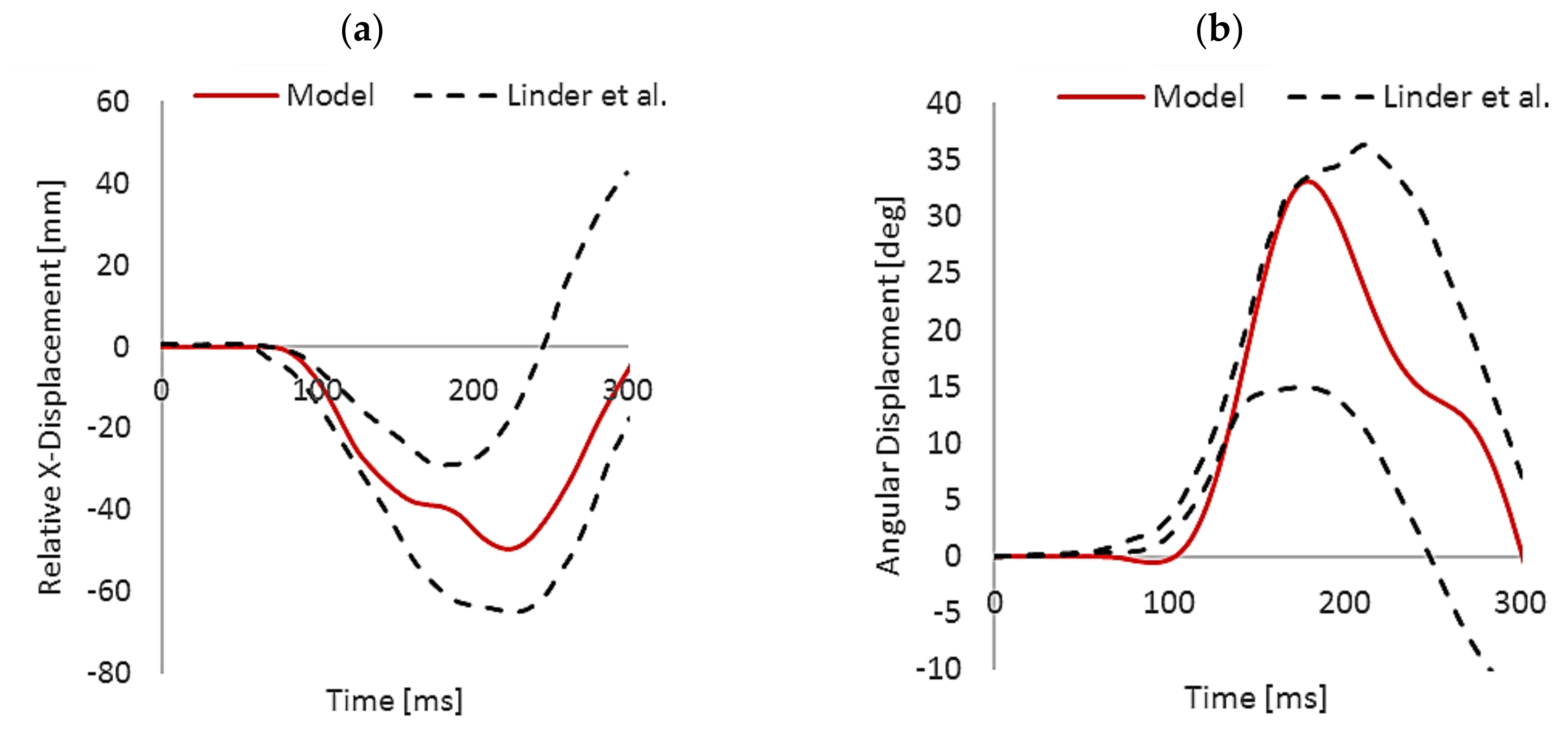
Validation of the human model responses has been extensively investigated in the literature. Its biomechanics were compared against several cadaver and volunteer human responses reported in the literature [9]. Besides those reported, an additional validation was achieved in this study by comparing its global relative kinematics against the volunteer rear-end impact test conducted by Linder et al. [22]. In their study, eight male volunteers were subjected to a 7 km/h velocity rear-impact profile and a mean acceleration of ~2 g. The test was performed using an adaptive seat with a head restraint backset gap of 150 mm. It is worth noting that a restraining harness was used instead of a 3-point seatbelt to ensure the volunteers’ safety at a high head restraint backset gap. Figure 2 presents the head retraction (x-displacement) movement concerning the torso and the head’s peak angular displacement. The resulted kinematic responses were found to be within the average motion corridors of the human subjects. Head retraction reached a maximum of 49.5 mm after 224 ms, whereas peak head extension was 33.1 degrees at 179 ms.

3.2. Head Retraction Phase

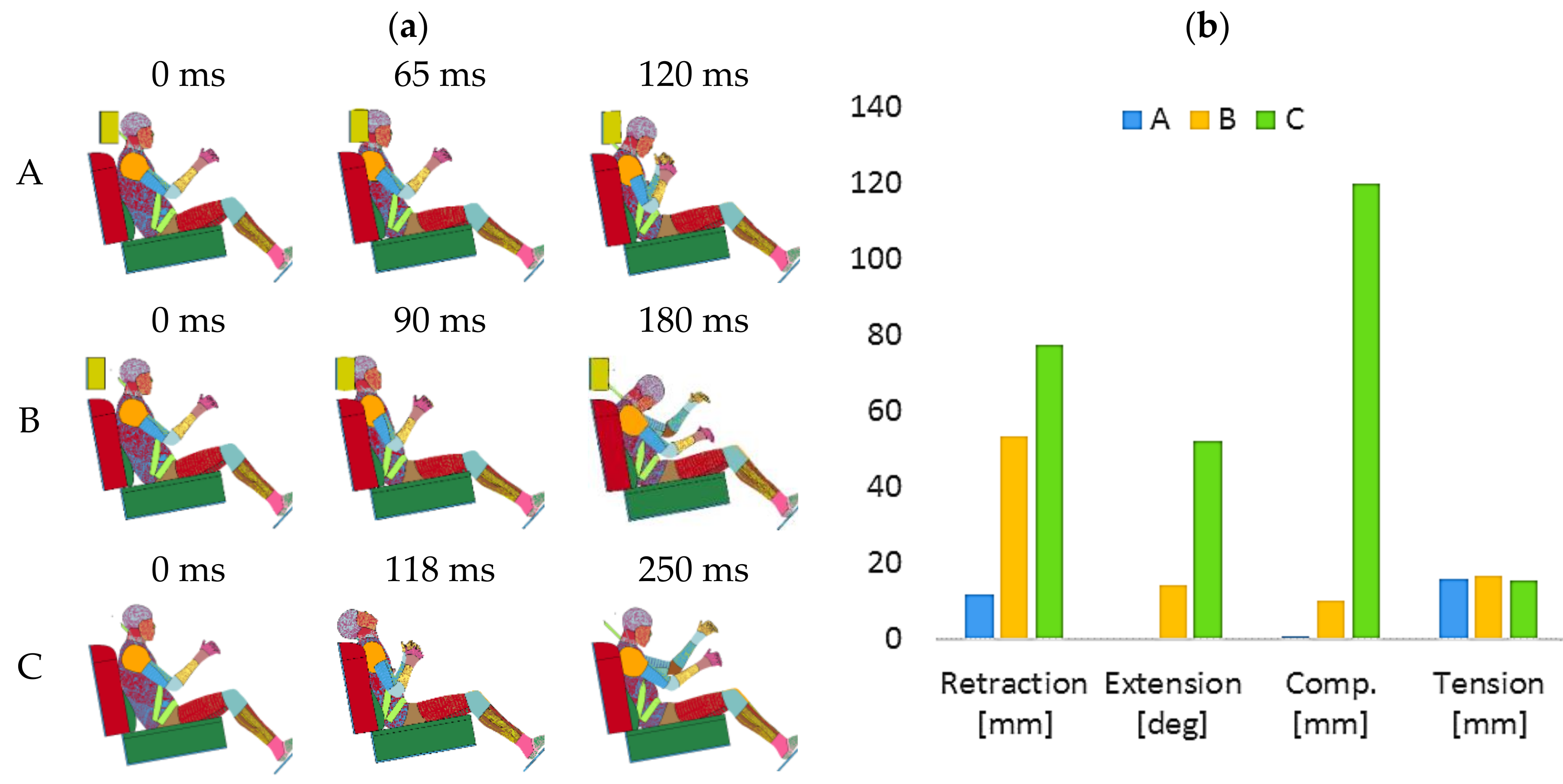
The overall cervical spine kinematics were divided into three distinct phases; the S-shape, hyperextension, and rebound phases [8]. The human body interactions with the accelerating seat, restraining seatbelt, and head restraint support are illustrated in Figure 3a. At the beginning of the impulse, the torso gradually absorbs kinetic energy while indenting into the seatback. Consequently, the torso begins to accelerate upward, depending on the passenger’s seatback angle and material properties [9]. Meanwhile, the unsupported head does not move accordingly and lags behind the torso due to its inertia. This, in turn, causes the neck to endure combined flexion and extension moments at the upper and bottom levels, respectively, to form what is known as an S-shape posture.
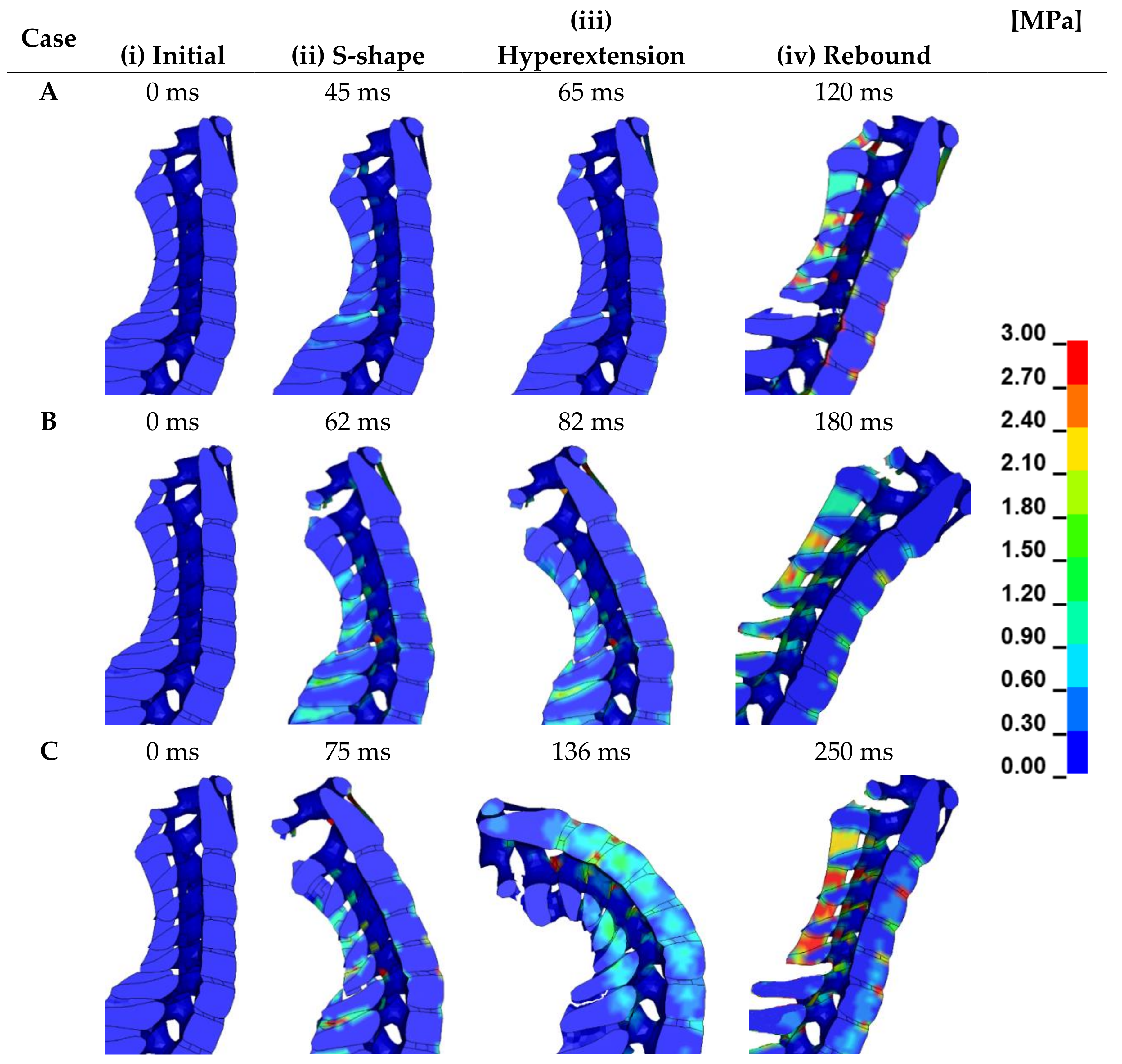
In comparison between the head restraint arrangements, the head retraction increased linearly with the head restraint-to-head gap distance (Figure 3b). Besides, the S-shape curvature becomes more severe when the head retracts further behind the torso. Arrangement A was more responsive in providing head support at an early stage before excessive head retraction (<12 mm). Therefore, the cervical structure sustained without failure against the stresses, as shown in Figure 4, A-ii. On the contrary, the poorly adjusted head restraint in Arrangements B and C has permitted the head to retract beyond 52 mm and 76 mm, respectively.
The cervical spine elements started to collapse and tear due to the vertebra’s excessive relative rotational movements. Firstly, the upper flexion moment forced the posterior ligaments (LF and ISL) to stretch beyond their physiological limit and fail in the craniovertebral region (Figure 4, B&C-ii). Accordingly, higher stresses were shifted to the CL and ITL ligaments due to increased S-shaped curvature. The ITL ligament was able to withstand those stresses due to its elasticity and strength [23]. Unlike the ITL, however, the CL ligaments were disrupted at C1–C2 facet joints. Secondly, the ISL ligament undertook significant shear stresses at the bottom spinous process (C6–C7–T1) owing to high neck contraction displacement due to extension motion. It is a very delicate ligament and will require long-term treatments to recover [14]. Lastly, shear stresses induced on the bottom IVDs have reached a significant level of more than 2.4 MPa (Figure 4, C-ii). Those will most probably produce damage to the outer annulus’ neural arch and delamination [12].

3.3. Hyperextension Phase

Once the kinetic energy is transferred to the head through the neck during the S-shape phase, it extends behind the torso. This extension moment results from the lever arm between the head’s center of mass and the OC’s pulling point. This, in turn, stretches the anterior ligaments and the annulus of the IVDs. Therefore, injuries are mostly limited to or originate from the spine’s anterior column [8]. Patients that have experienced rear-end collision often sustain anterior ligament ruptures and disk separation, which lends weight to the hyperextension mechanism [12]. The degree of injury and symptom chronicity depends on the amount of extension that occurs. Figure 3b indicates that the neck experiences complex motion, in Arrangement C, comprised of hyperextension (>56°) combined with elevated compressive displacement (>120 mm). The extent of those relative motions is well beyond the neck’s threshold tolerance levels [14]. Thus, the presence of head restraint in the vehicle is essential for the safety of the occupant. Although the head restraint in Arrangement B was misplaced, it had a significant impact in lowering the peak neck compression and extension by 72% and 91%, respectively (Figure 3b). On the other hand, Arrangement A has eliminated the relative kinematics since it supported the head in the former phase.
Without head restraint support, the posterior and anterior spinal columns were subjected to sufficient compression and tension loads, respectively, to cause sprains and fractures in its osteoligamentous structure (Figure 4, C-iii). The former stresses were higher than 120 MPa owing to the interface between the C3–C6 spinous process (Figure 5c). Accordingly, microcracks initiation within their cancellous bones were likely to occur [24]. Besides, since the ISL, LF, and CL ligaments have failed in the craniovertebral region, the relative motions between the atlas and axis vertebras were no longer fully constrained. Hence, contact stresses between them were generated, as seen in Figure 4, C-iii. These stresses have up to a 20% probability of causing an unstable type II odontoid fracture in the C2 dens or initiating cancellous bone cracks in C1 and facet joints [25]. In this case, the immediate intervention of anterior screw fixation surgical treatment is required to provide rigid support for the fracture and unify with the preservation of atlantoaxial rotation [25].
Disruption of the ALL ligament occurred at C3–C5 levels due to exposure to tensile stresses beyond 30 MPa, which exceeds its material capabilities (Figure 5a). Furthermore, stable avulsion fracture from the attachments to the inferior corner of the C4 vertebral body (Figure 4, C-iii). As stated by Yoganandan et al. [26], an added range of movement due to neck hyperextension can eventually cause long-term segmental spinal instability and spine degeneration. The PLL and CL ligaments did not endure harmful stresses since they are located on the middle neutral column, and thus their failure is not foreseen in this stage.
Regarding the IVDs, they undertook a complex combination of stresses beyond their physiological limit (greater than 3 MPa), especially at the C3–C4 interface (Figure 5b) [12]. Therefore, the probability of promoting radial fissures and disc prolapse (slipped disc) is very high [12]. It is worth mentioning that those injuries are hazardous and will require years to heal. All the previously mentioned neck injuries can be avoided by adjusting the head restraint properly, similar to Arrangement A. This allows the head restraint to absorb the head’s kinetic energy and lower its relative rotational motion with the torso, which neglected neck extension.
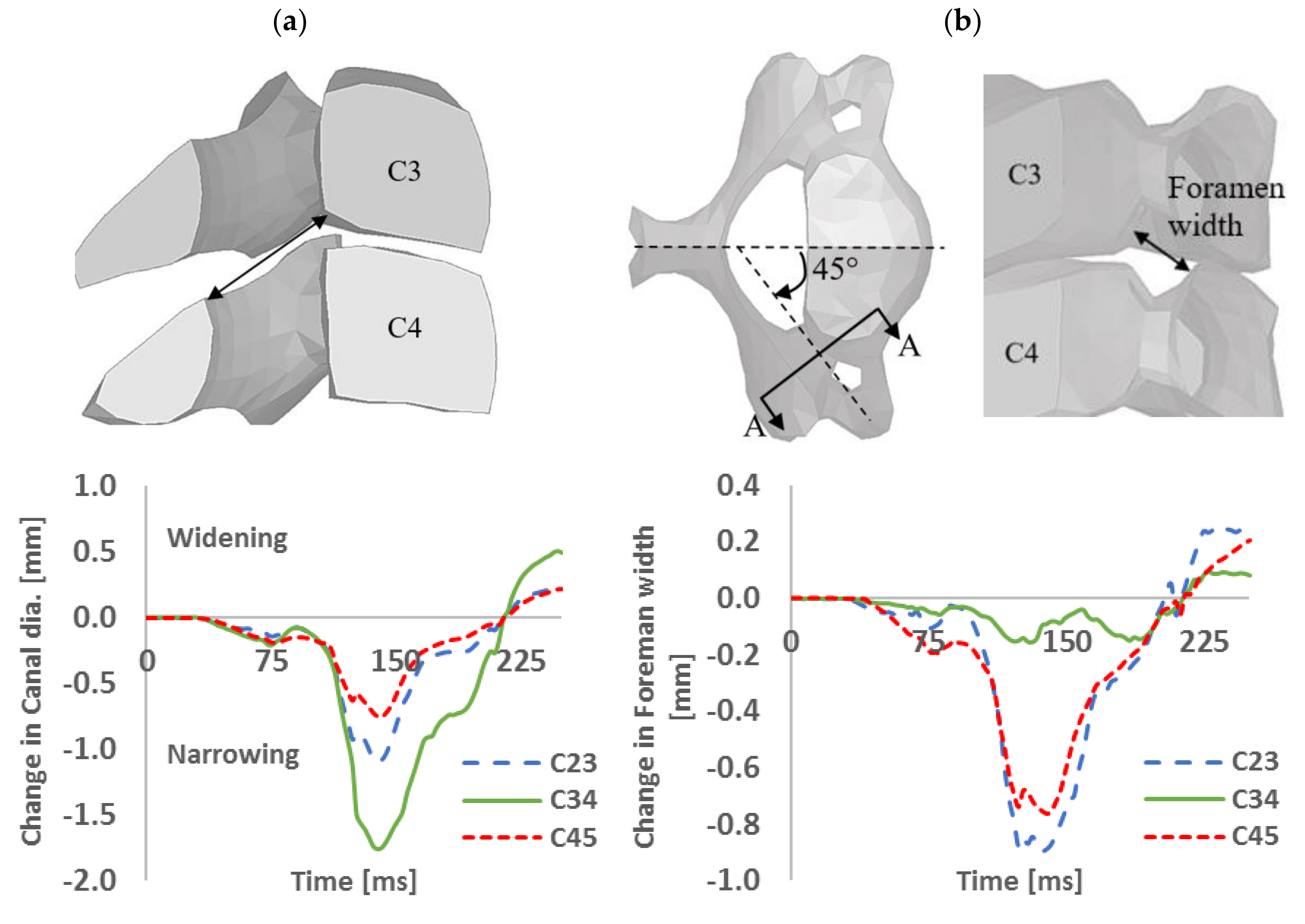
Peak levels of neural space narrowing were observed at the upper C2–C4 intervertebral segments during the hyperextension phase. Lateral structural displacements have narrowed the canal diameter by a peak of 1.8 mm at the C3–C4 level in Arrangement C (Figure 6a). This, in turn, has built hydrodynamic pressure gradients in the spinal cord [15].
Pressure levels reached a maximum of 114 kPa were observed in the OC–C1 segment (Figure 7c). This level exceeds the tolerance threshold and will most likely contribute to chronic dysfunction of the nerve roots involved [27]. The foramen width, measured at 45° to the midsagittal plane, was reduced by 0.87 mm at the C2–C3 level (Figure 6b). Consequently, the ganglia and nerve roots were subjected to potential injury. Since the spinal fluid is incompressible, this causes an outward displacement of the spinal canal’s contents [27]. Blood within the anterior internal venous plexus moves through the foramen to the anterior external venous plexus [27]. At the same time, cerebrospinal fluid enters through the nerve root sleeves.
The increased amount of blood and cerebrospinal fluid leads to additional compressive loads being applied to nerve roots. Further, the craniocervical junction ligaments, such as the alar and transverse ligaments, were protruded and buckled inwardly, which most likely applies additional pressure on those roots. The head restraint in the other arrangements with head restraint involvement has minimized these pressure gradients by more than 50 percent (Figure 7). The fact that occupants of vehicles involved in rear-end collisions often experience neck and shoulder pain adds more credit to the previous causes.

3.4. Neck Flexion Phase

The head rebound phase begins when the head restraint releases its stored energy after the maximum indentation. This energy causes the head to rebound at a specific rate, and at the same time, the cervical spine straightens [26]. This rate is influenced by the seat design and its material properties. In Arrangement C, the rebound interval started when the seatbelt restrained the torso rebounding motion after the neck extension at 136 ms (Figure 3a). The head’s relative velocity with the torso was lower than the other arrangement since the head restraint was not present to provide the head with additional energy. Simulated results were terminated at the end of the rebound phase for A (good), B (poor), and C (without head restraint) Arrangements at 120, 180, and 250 ms, respectively.
Variations in the neck tension between the three head restraint arrangements were insignificant due to the absence of airbag deployment (Figure 3b). Overall, a maximum elongation of less than 19.6 mm was recorded within acceptable neck displacement boundaries. However, the peak head flexion angle of 32 degrees relative to the T1 was beyond the safe range of motion [11]. Consequently, the posterior cervical ligaments were the most load-bearing components, followed by the cancellous bone, CL, and IVDs. The results suggest that ISL and LF ligaments were strained at a high rate, especially in Arrangements A and B, and thus failed at multiple bottom levels (Figure 4, A&B-iv). Similar observations were reported from experimentation on intact biofidelic fresh-frozen cadaveric cervical spines [28].
The middle and lower cervical spine (C3–C4 through C6–C7) were the most vulnerable segments for ISL and LF failure at low impacts and throughout the entire spine at 10 g impact. In general, the ISL was at higher elongations than LF, possibly because they are located at a greater distance from the center of rotation during hyperflexion. There was no sign of a teardrop fracture of the anteroinferior aspect of the C2–C4 vertebral bodies since the hyperflexion motion was combined with tension rather than compression displacements. However, their corresponding IVD was exposed to pinching stresses from the anterior annular fiber layer [12] (Figure 4, C-iv). Those stresses were higher than the injury tolerance of 2.7 MPa [12].
Failure of the posterior ligaments has added additional structural instability resulting in increased compressive loadings on the anterior IVDs and leading to disc and facet degeneration. As a result, chronic pain will appear from facet joint osteoarthritis, as demonstrated by radiographic studies [28]. Fortunately, those injuries were not accommodated by a displacement of the posterior portion of its body into the spinal canal. Therefore, injury to the spinal cord was not predicted in this stage.
Stresses on the CL were the greatest at C4–C6 levels and infrequently exceeded the sub failure injury threshold at 3.5 MPa. Therefore, they are less likely to be injured. Those injuries do not lead to death, but the joints cartilage may bleed and get damaged, which will promote chronic long-term neck pain [12]. They are more vulnerable when the flexion motion is combined with an axial rotational moment, as shown at the end of Arrangement B in Figure 4, B-iv. These rotational moments most likely appear from the three-point restraining seatbelt, where one shoulder of the torso is fully restrained, unlike the other. Studies predicted that they would carry up to 70 percent of the total load, which leads to failure in its structures [11]. Since this stage was comprised of chronic injuries at multiple levels, an airbag deployment system is mandatorily equipped in vehicles.
It is worth mentioning that ligaments and bony injuries predicted by the FE model provided insights into the neck response to rear-end collision and highlighted the most vulnerable cervical components to fail. However, these results should not be considered a final statement before further investigation utilizing extensive clinical trials. Several limitations were associated that may or may not affect the biofidelity of the study. For instance, muscle pre-tension was not defined in the human model to establish equilibrium spinal posture and active structural responses. Besides, the availability of cervical components’ material properties and injury thresholds were limited with some diversity in their values, which may have caused prediction variations in the prolonged, painful response.

4. Conclusions

Overall, head restraints have exhibited adequate neck protection towards limiting peak shear and extension displacements during the retraction stage. Even the poorly adjusted one has reduced the relative kinematics by 72 percent. Tissue-level injuries were mainly caused by hyperflexion motion during the rebound phase regardless of the head restraint position. That is true, especially when this motion was combined with axial rotation, due to the three-point restraining seatbelt, where further loads were subjected to the intertransverse and capsular ligaments. The interspinous and ligamentum flavum ligaments were the most vulnerable cervical components in the entire spine. During the s-shape stage, their sprain occurred when the head restraint was poorly positioned and thus caused relative motion instabilities between the atlas and axis vertebra. This, in turn, caused the intervertebral discs, capsular ligaments, and facet joints at the craniovertebral level to undergo high compressive stresses beyond their physiological injury threshold. A stable extension-teardrop avulsion fracture of the anteroinferior aspect of the fourth vertebral body occurred when the head restraint was absent. Accordingly, the anterior longitudinal ligament was ruptured, whereas the posterior longitudinal ligament remained intact. Lastly, the spinal cord at the craniocervical level underwent high hydrodynamic pressure gradients due to the structure’s unstable relative motions. Moreover, the ganglia and nerve roots were subjected to sufficient compressive loads to cause injury due to narrowing in their neural space. Consequently, chronic shoulder pain and numbness are common symptoms of post whiplash trauma due to the dysfunction of those roots.
These findings illustrate the complexity of the injury that extends to not only damage to cervical muscles and ligaments but also its nervous system and vertebral body fractures. These injuries are related to head–torso relative kinematics that is highly dependent on the head restraint position, as demonstrated in this study. A more representative neck injury criterion can be developed as per these relations that can predict the level of the injury. Such criterion will provide significant insights into the effect of various safety design parameters in limiting whiplash injuries.
A properly adjusted head restraint was very effective in limiting potential whiplash injuries. However, having the need to manually adjust the head restraint every time an occupant sits in the vehicle or change his posture while driving is not practical. Unfortunately, active head restraint systems are being featured only on luxury cars as an advanced safety pack with other features such as road-assist lane monitoring. There is a need to make it mandatory to equip every new vehicle with an active head restraint system and develop a retrofit system for the older models.

Author Contributions

Conceptualization, O.L. and E.M.; Formal analysis, O.L., E.M. and J.-J.C.; Funding acquisition, E.M.; Investigation, O.L. and J.-J.C.; Methodology, E.M.; Writing—original draft, O.L. and E.M.; Writing—review & editing, J.-J.C. All authors have read and agreed to the published version of the manuscript.

Funding

The authors would like to acknowledge the financial support of the Qatar National Research Fund (a member of the Qatar Foundation) through the National Priorities Research Program NPRP#6-292-2-127. The work was supported in part by a research grant from Qatar University under the grant number IRCC-2019-001.

Conflicts of Interest

The authors certify that they have no affiliations with or involvement in any organization or entity with any financial interest or non-financial interest in the subject matter or materials discussed in this manuscript. Ethical approval was not required since this study did not involve human nor animal subjects. The data collected in this study is not publicly available due to research work copyrights.

References

  1. Li, F.; Liu, N.; Li, H.; Zhang, B.; Tian, S.; Tan, M.; Sandoz, B. A review of neck injury and protection in vehicle accidents. Transp. Saf. Environ. 2019, 1, 89–105. [Google Scholar] [CrossRef]
  2. Oliphant, K. The Whiplash Capital of the World”: Genealogy of a Compensation Myth. In Damages and Compensation Culture: Comparative Perspectives; Hart Publishing: London, UK, 2016; pp. 15–36. [Google Scholar]
  3. Bener, A.; Rahman, Y.S.A.; Mitra, B. Incidence and severity of head and neck injuries in victims of road traffic crashes: In an economically developed country. Int. Emerg. Nurs. 2009, 17, 52–59. [Google Scholar] [CrossRef] [PubMed]
  4. Stemper, B.D.; Yoganandan, N.; Pintar, F.A. Effect of head restraint backset on head–neck kinematics in whiplash. Accid. Anal. Prev. 2006, 38, 317–323. [Google Scholar] [CrossRef] [PubMed]
  5. Trempel, R.E.; Zuby, D.S.; Edwards, M.A. IIHS head restraint ratings and insurance injury claim rates. Traffic Inj. Prev. 2016, 17, 590–596. [Google Scholar] [CrossRef] [PubMed]
  6. Van Oosterwijck, J.; Nijs, J.; Meeus, M.; Paul, L. Evidence for central sensitization in chronic whiplash: A systematic literature review. Eur. J. Pain 2013, 17, 299–312. [Google Scholar] [CrossRef]
  7. Forman, J.L.; Lopez-Valdes, F.J.; Duprey, S.; Bose, D.; de Dios, E.D.; Subit, D.; Gillispie, T.; Crandall, J.R.; Segui-Gomez, M. The tolerance of the human body to automobile collision impact–a systematic review of injury biomechanics research, 1990–2009. Accid. Anal. Prev. 2015, 80, 7–17. [Google Scholar] [CrossRef]
  8. Ivancic, P.C.; Sha, D.; Lawrence, B.D.; Mo, F. Effect of active head restraint on residual neck instability due to rear impact. Spine 2010, 35, 2071–2078. [Google Scholar] [CrossRef] [Green Version]
  9. Iwamoto, M.; Nakahira, Y.; Kimpara, H. Development and validation of the total human model for safety (THUMS) toward further understanding of occupant injury mechanisms in precrash and during crash. Traffic Inj. Prev. 2015, 16, S36–S48. [Google Scholar] [CrossRef] [Green Version]
  10. Broos, J.; Meijer, R. Simulation Method for Whiplash Injury Prediction Using an Active Human Model. In Proceedings of the IRCOBI Conference—International Research Council on the Biomechanics of Injury, Malaga, Spain, 14–16 September 2016. [Google Scholar]
  11. Mustafy, T.; Moglo, K.; Adeeb, S.; El-Rich, M. Injury mechanisms of the ligamentous cervical C2–C3 functional spinal unit to complex loading modes: Finite element study. J. Mech. Behav. Biomed. Mater. 2016, 53, 384–396. [Google Scholar] [CrossRef]
  12. Newell, N.; Little, J.P.; Christou, A.; Adams, M.A.; Adam, C.J.; Masouros, S.D. Biomechanics of the human intervertebral disc: A review of testing techniques and results. J. Mech. Behav. Biomed. Mater. 2017, 69, 420–434. [Google Scholar] [CrossRef]
  13. Panzer, M.B.; Cronin, D.S. C4–C5 segment finite element model development, validation, and load-sharing investigation. J. Biomech. 2009, 42, 480–490. [Google Scholar] [CrossRef] [PubMed]
  14. Mattucci, S.F.; Moulton, J.A.; Chandrashekar, N.; Cronin, D.S. Strain rate-dependent properties of younger human cervical spine ligaments. J. Mech. Behav. Biomed. Mater. 2012, 10, 216–226. [Google Scholar] [CrossRef] [PubMed] [Green Version]
  15. El-Rich, M.; Arnoux, P.; Wagnaca, E.; Brunet, C.; Aubin, C. Finite element investigation of the loading rate effect on the spinal load-sharing changes under impact conditions. J. Biomech. 2009, 42, 1252–1262. [Google Scholar] [CrossRef] [PubMed]
  16. Iwamoto, M.; Kisanuki, Y.; Watanabe, I.; Furusu, K.; Miki, K.; Hasegawa, J. Development of a finite element model of the total human model for safety (THUMS) and application to injury reconstruction. In Proceedings of the International IRCOBI Conference, Munich, Germany, 18–20 September 2002. [Google Scholar]
  17. Cheng, S.; Clarke, E.C.; Bilston, L.E. Rheological properties of the tissues of the central nervous system: A review. Med. Eng. Phys. 2008, 30, 1318–1337. [Google Scholar] [CrossRef]
  18. Mohanty, P.P.; Mahapatra, S. A finite element approach for analyzing the effect of cushion type and thickness on pressure ulcer. Int. J. Ind. Ergon. 2014, 44, 499–509. [Google Scholar] [CrossRef]
  19. Briody, C.; Duignan, B.; Jerrams, S. Testing, modelling, and validation of numerical model capable of predicting stress fields throughout polyurethane foam. In Proceedings of the 7th European Conference on Constitutive models for Rubber, Munich, Bavaria, 28–31 August 2011. [Google Scholar]
  20. RCAR-IIWPG Seat/Head Restraint Evaluation Protocol (Version 3). 2008. Available online: www.iihs.org/media/84f361de-a61a-4614-985c-c420c1d20634/1846913147/Ratings/Protocols/current (accessed on 12 August 2020).
  21. Beck, B.; Brown, J.; Bilston, L.E. Variations in rear seat cushion properties and the effects on submarining. Traffic Inj. Prev. 2011, 12, 54–61. [Google Scholar] [CrossRef]
  22. Linder, A.; Schick, S.; Hell, W.; Svensson, M.; Carlsson, A.; Lemmen, P.; Schmitt, K.; Gutsche, A.; Tomasch, E. ADSEAT–Adaptive seat to reduce neck injuries for female and male occupants. Accid. Anal. Prev. 2013, 60, 334–343. [Google Scholar] [CrossRef]
  23. Yoganandan, N.; Pintar, F.; Butler, J.; Reinartz, J.; Sances, A., Jr.; Larson, S.J. Dynamic response of human cervical spine ligaments. Spine 1989, 14, 1102–1110. [Google Scholar] [CrossRef]
  24. Anastasilakis, A.D.; Polyzos, S.A.; Makras, P.; Aubry-Rozier, B.; Kaouri, S.; Lamy, O. Clinical features of 24 patients with rebound-associated vertebral fractures after denosumab discontinuation: Systematic review and additional cases. J. Bone Miner. Res. 2017, 32, 1291–1296. [Google Scholar] [CrossRef] [Green Version]
  25. Marwan, Y.; Kombar, O.R.; Al-Saeed, O.; Aleidan, A.; Samir, A.; Esmaeel, A. The feasibility of two screws anterior fixation for Type II odontoid fracture among Arabs. Spine 2016, 41, E643–E646. [Google Scholar] [CrossRef] [Green Version]
  26. Yoganandan, N.; Stemper, B.D.; Rao, R.D. Patient mechanisms of injury in whiplash-associated disorders. Semin. Spine Surg. 2013, 25, 67–74. [Google Scholar] [CrossRef]
  27. Chen, H.B.; King, H.Y.; Wang, Z.G. Biomechanics of whiplash injury. Chin. J. Traumatol. 2009, 12, 305–314. [Google Scholar] [PubMed]
  28. Panjabi, M.M.; Pearson, A.M.; Ito, S.; Ivancic, P.C.; Gimenez, S.E.; Tominaga, Y. Cervical spine ligament injury during simulated frontal impact. Spine 2004, 29, 2395–2403. [Google Scholar] [CrossRef] [PubMed]
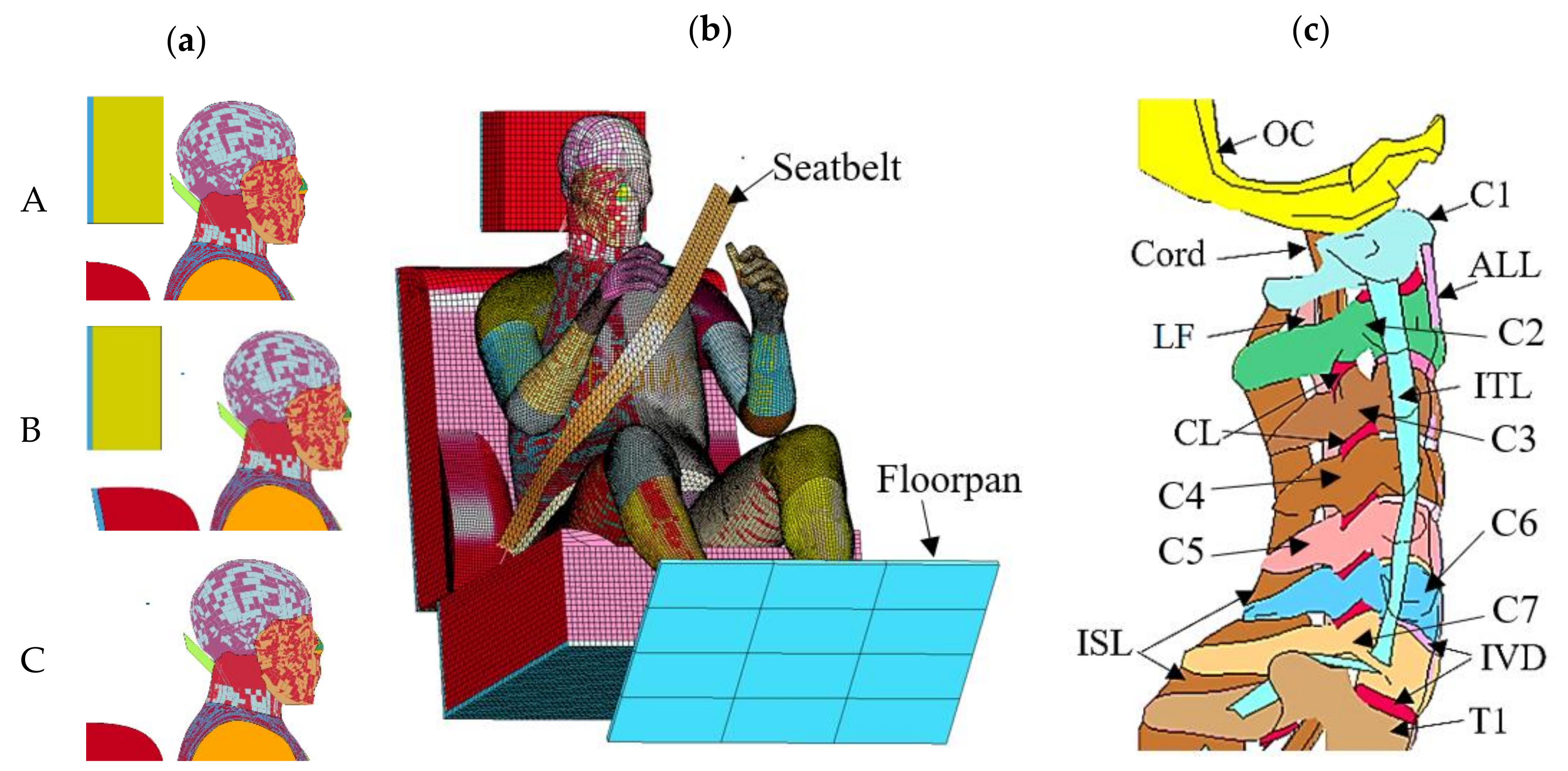
Figure 1. (a) Side views of head restraint Arrangements A (good), B (poor), and C (without head restraint), (b) isometric view of a human model seated on an inclined chair with three-point seatbelt and a floorpan, and (c) side view of the cervical spine bony structure including occipital condyle (OC), entire cervical vertebra (C1–C7), and the first thoracic vertebra (T1), and the associated ligaments such as anterior longitudinal ligament (ALL), intertransverse ligament (ITL), ligamentum flavum (LF), capsular ligament (CL), interspinous ligament (ISL), and intervertebral discs (IVDs).
Applsci 11 00145 g001
Figure 2. Comparison between the developed model results and Linder et al. [22] reported data of eight male volunteers in terms of (a) head retraction in horizontal axis relative to the first thoracic vertebra and (b) head angular displacement.
Applsci 11 00145 g002
Figure 3. (a) Side view of simulated occupant response for A (good), B (poor), and C (without head restraint) with (b) their corresponding peak relative neck retraction, compression, tension, and extension measured between the occipital condyle (OC) and the first thoracic vertebra (T1).
Applsci 11 00145 g003
Figure 4. Effective stress levels (MPa) at the sagittal view for cervical cancellous bones and ligaments. Responses were captured for A, B, and C Arrangements at (i) initial posture, (ii) S-shape, (iii) hyperextension, and (iv) head rebound phases.
Applsci 11 00145 g004
Figure 5. Bar charts representing peak effective stress levels (MPa) recorded at (a) cervical ligaments, (b) intervertebral discs, and (c) cortical bony structure. Data bars labeled with (*) indicates failure occurred to the component.
Applsci 11 00145 g005
Figure 6. Schematic sketch of (a) the sagittal spinal canal and (b) superior view with an intervertebral section view of the C3–C4 cervical foraminal area. The canal diameter was measured from the posteroinferior corner of C3 to the superior end of C4 at the sagittal plane, whereas the foramen width was the shortest distance between the anterior of C3 to the posterior of C4 at the AA plane. The line graphs in (a), (b) represent the change in canal diameter and foramen width concerning time, respectively, at C2–C3, C3–C4, and C4–C5 intervertebral segments for Arrangement C (without head restraint).
Applsci 11 00145 g006
Figure 7. Sagittal screens of spinal cord effective stress levels (MPa) during neck hyperextension phase for head restraint arrangement (a) A at 63 ms, (b) B at 73 ms, and (c) C at 124 ms.
Applsci 11 00145 g007
Table 1. Material properties of the cervical spine components.
ComponentConstitutive ModelMaterial Properties (ρ 10−6 kg/mm3, σ MPa)Ref.
CorticalJohnson and Cook Elasto-plastic ρ = 1.82 ,   σ f = 155 ,   E = 16800 ,   σ y = 110 ,
ν = 0.3 ,   b = 100 ,   n = 0.1 ,   c = 1
[11]
CancellousJohnson and Cook Elasto-plastic ρ = 0.17 ,   σ f = 2.23 ,   E = 100 ,   σ y = 1.92 ,
ν = 0.29 ,   b = 20 ,   n = 1 ,   c = 1
[11]
Nucleus pulposusFluid ρ = 1 ,   K = 1720 [12]
Annulus fibrosusHill hyper-elastic ρ = 1.2 ,   σ f = 2.7 , ε f = 0.3 ,   n = 2 ,
C 1 = 0.115 ,   C 2 = 2.101 ,   C 3 = 0.893 ,
β 1 = 4 ,   β 2 = 1 ,   β 3 = 2
[13]
Spinal cordQuasilinear viscoelastic E = 1.37 ,   ε f = 10 % ,   A = 0.028 ,   B = 25.9 ,
τ 1 = 4.38 ,   τ 2 = 0.554 ,   τ 3 = 234.4 ,
G 1 = 0.104 ,   G 2 = 0.121 ,   G 3 = 0.377
[17]
Muscles3D Feng hyper-elastic (bulky muscles),
1D nonlinear (thin muscles)
ρ = 1.05 ,   K = 4.59 ,   μ = 0.1
Nonlinear loading/unloading curves
[16]
LigamentsGeneralized Maxwell and Kelvin–Voigt viscoelastic E ν E t ν t η 0 λ σ f [14,15]
ALL500.4100.42281e631.9
PLL630.499.00.42281e629.3
ITL11.40.411.00.42281e6-
ISL13.70.394.00.42281e64.5
LF24.60.395.00.42281e65.6
CL6.90.3922.00.42281e63.5
Table 2. Driver seat overall dimensions and soft-cushion material properties for Ogden hyper-elastic model.
DimensionsBackrestBaseHead Restraint
Cushion length (mm)585200640
Cushion width (mm)530250530
Cushion Thickness (mm)151120160
Wing width (mm)130-100
Wing Thickness (mm)53-30
Material PropertiesBackrest/BaseHead Restraint
Density, ρ (kg/m3)6040
Stiffness, E (kPa) 200 20
Relaxation modulus, G 1 ,   G 2 0.3003, 0.19970.0973, 0.174
Relaxation time, τ 1 ,   τ 2   (sec)0.010014, 0.10020.30639, 11.21
Shear modulus μ 1 ,   μ 2 (kPa)4.81, 3.644.185, 0.0037
Exponent coefficient α 1 ,   α 2 19.8, 19.821.4556, −6.89
Decay constant β 1 ,   β 2 (10−2)0.0145, 0.650, 0
Publisher’s Note: MDPI stays neutral with regard to jurisdictional claims in published maps and institutional affiliations.