1. Introduction
There are two common types of railway track are used in railway engineering: (a) ballasted track with concrete sleeper or wooden sleeper, and (b) non-ballasted or slab track structure. The ballasted track which is installed with concrete sleepers has been widely used for conventional lines. The main advantages of this type of track are good elasticity, low initial construction cost, and ease of maintenance [
1]. However, the ballasted track also has essential drawbacks such as high maintenance cost, fouled ballast, or insufficient support to the track structures. The track degradation’s main causes are ballast fouling and insufficient depth of ballast [
2]. Therefore, it is necessary to develop and research a non-destructive method such as ground penetrating radar (GPR) to limit these problems because the capacity of drainage in railway infrastructure is highly dependent on the fouled ballast [
3]. Compared to the ballasted track, the non-ballasted or slab track has lower maintenance cost. It has been developed and become more popular in Korea, Japan, China, and Europe. Due to the advanced behaviors such as good resistance in lateral and longitudinal direction and limiting of the buckling problem the slab track system is a suitable choice to apply for high-speed or metro railway track in tunnels, underground sections and bridges [
4].
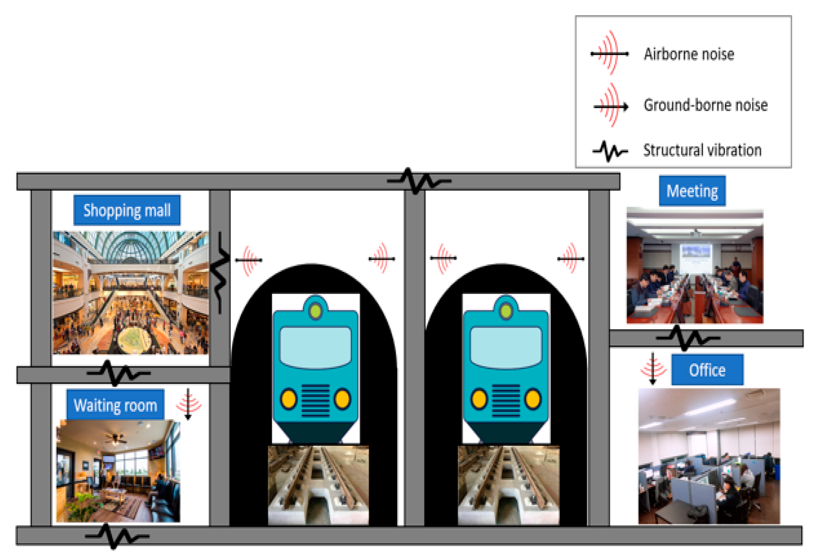
Nowadays, railway networks have been developed rapidly and the popular way to construct the infrastructure is to use the idle space below the tracks, especially for urban railway stations. However, by using the conventional slab track (cast in-situ method), the ground-borne noises and vibrations generated from railway facilities during the train operations have become a severe problem [
5]. As can be seen in
Figure 1, at a railway station, the dynamic loads of the trains will be transmitted through the rails and slab track to the pillars, walls, and so on, which are the main structures that form the framework of the station [
6]. So, it is more effective to find countermeasures that address the source of the noise, which are more economically and intrinsically efficient for existing railway stations [
7].
A floating slab track is one way to minimize the ground-borne vibration noise by blocking the vibration transmitted from the vehicle–track interaction [
8]. This type of track is generally made of the continuous rail, mounted on the massive concrete by the fastening devices and forming the mass–spring–systems (MSS). The combination of the panel’s weight with a dead load of superstructures (rails, fastening systems, and sleepers) created the dynamically active mass [
9]. Under this type of track, the anti-vibration device such as the glass fiber, rubber bearing, or coil springs [
10] is installed as a substructure to disconnect the track from the ground and decrease the magnitude of the load generated by the wheel-rail, and this method is widely used and accepted for railway tracks in Korea and around the world [
11,
12,
13,
14,
15,
16,
17,
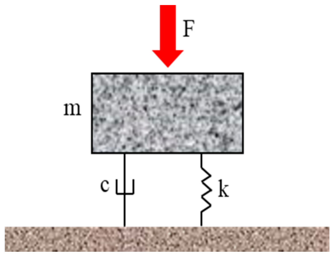
18]. In floating slab tracks, the rails are usually used as the connection between panels instead of dowel bars to reduce the construction cost. To simulate the performance of this type of track system, the easiest way is to consider it as a single degree of freedom as shown in
Figure 2 with F is load, m is the mass of the track structures, k is the stiffness of substructure and c is the damping factor of the system. The biggest deterrent of this type of railway structure is the huge initial construction cost. However, recent studies about the life cycle cost of railway structures pointed out that this type of track can be an alternative method of the ballasted track or conventional concrete track with several advantages such as lower maintenance cost, rapid construction, and lower structure height [
19].
In this study, we determined whether a precast floating track, which was manufactured in a factory, transported, and installed at a construction site, could be a suitable solution to reduce the noise and vibration problems. Our study utilized a precast floating slab track structure, which is a newly developed structure, unlike existing conventional track structures. We assessed the precast floating track panel structure using the finite element method (MIDAS CIVIL program) and structural assembly tests to verify its structural performance. The goal of these tests was to evaluate the displacement of the rail and panel to verify the safety of this system through the load transfer efficiency.
2. Precast Floating Panel
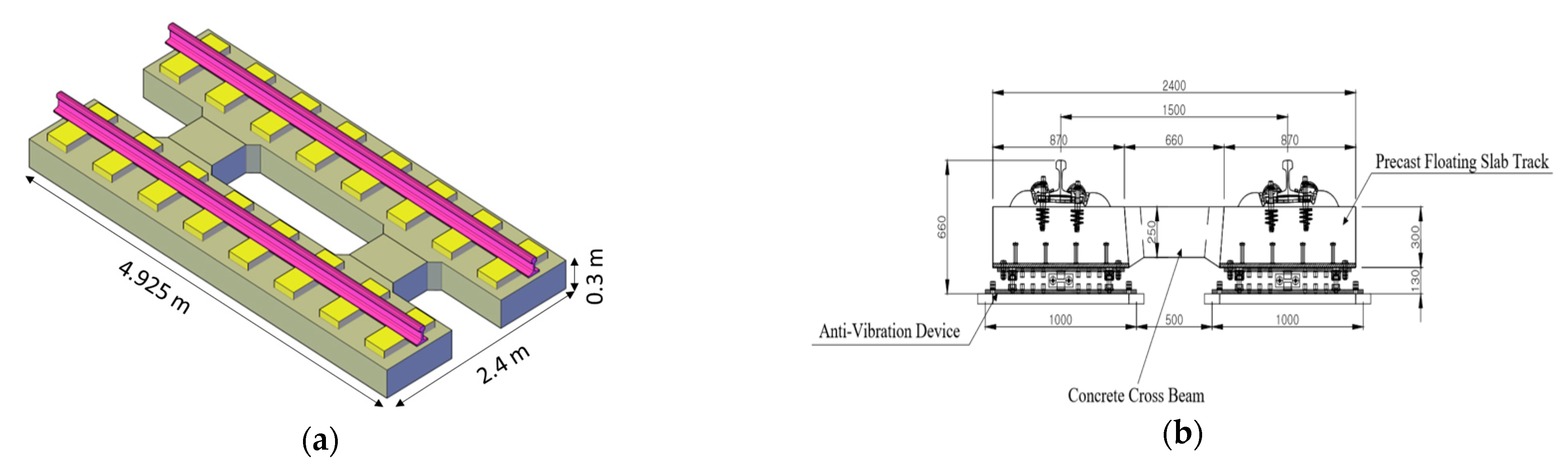
This study focuses on a new type of precast floating panel developed by the Korea Railroad Research Institute (KRRI).
Figure 3 shows a 3D-modeling and the cross section of this type of panel. The dimensions of the panel were 4.925 m (length) × 2.4 m (width) × 0.3 m (thickness). Rail and the slab panel was connected by fastening device (System 300-1, KR type).
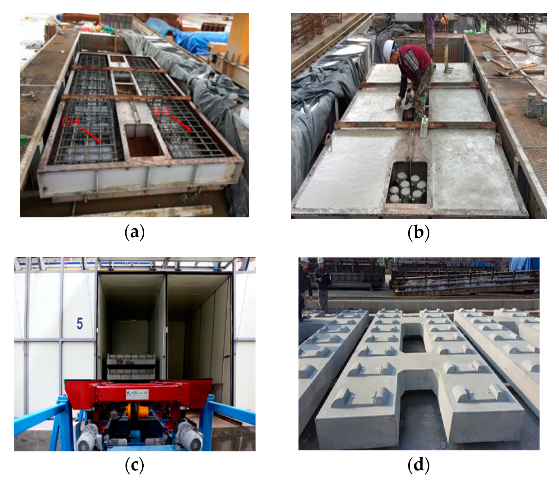
The fabrication process of the precast floating panel is shown in
Figure 4. Rebars D19 (longitudinal direction) and D13 (horizontal direction) were installed in a formwork, after completing the formwork, concrete was poured (
Figure 4b) and the curing process was carried out (
Figure 4c) until the compressive strength of concrete (
f’c) reached 45 MPa (
Figure 4d). This type of track can be installed in a limited amount of time after the existing ballasted track is removed. This design has six anti-vibration devices that are attached to the bottom of one of the precast track panels. The panel is composed of assembly blocks that are connected by concrete crossbeams. The panels are transported to the construction sites for rapid installation and are assembled to a fixed track height by adjusting the base, which is aligned in advance with the upper part of the station slab. The precast floating slab panels are installed sequentially on a flat plane using a hydraulic jack, and a high-precision survey is used to make linear corrections. The anti-vibration isolator uses a wedge-type engineering plastic block to attenuate the vibrations in the vertical direction, through frictional resistance. This provides restorative forces through the coil springs, which are arranged in the lateral and vertical directions to insulate against any vibrations.
3. Experimental Program
To evaluate the structural safety of the prefabricated floating track, we tested the bending performance of the slab panel in conjunction with a designed trainload. The performance of the vibration control system was compared with the stability of the track system and its ability to resist train loads. The detailed specifications of the slab panel are shown in
Table 1. The test was conducted using the same structural assembly specimens, to evaluate the behavior of track systems, which consisted of rails, slab panels, and vibration isolators composed of precast panels. The test was carried out by applying loads on the three-panel test, two load cases were conducted: loaded on the 2nd panel at the 2/4 point, and on the 2nd panel at 4/4 point.
Table 2 shows the specifications of the load test. In load case I, the maximum bending capacity of the structure was verified through the deflection of rail and panel. Meanwhile, the purpose of load case II was to determine the load transfer efficiency between the panels. According to the Korea construction rules for the railroad (Rule number 16), in the tunnel section, the standard live load EL-18 was used to apply for the designed load (180 kN) and in preparation for installing this type of track in conventional line [
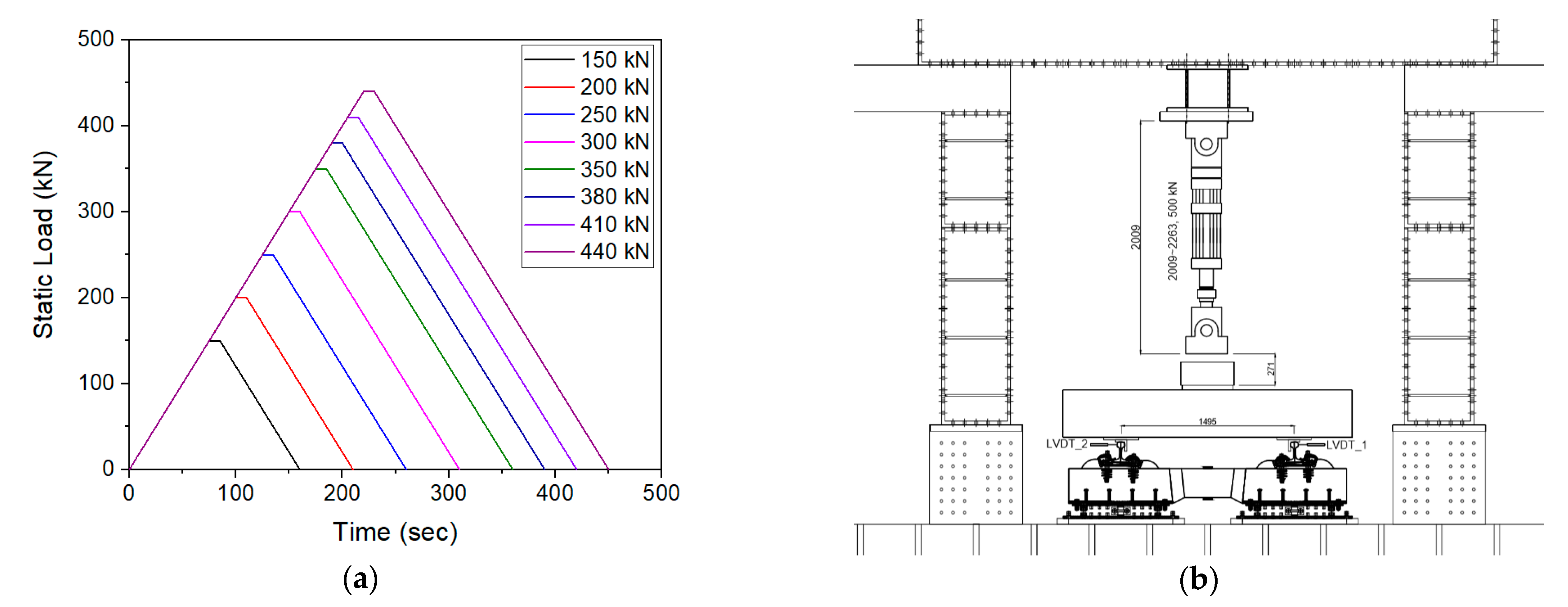
20], more than 250 kN of axle load must be reviewed so that the test was performed through the load up to 440 kN which is calculated based on the static axle load of Korean standard (KRL-2012) for conventional passenger and freight train (220 kN) and the dynamic amplification factor (2.00) according to Eisenmann formula [
1]. In
Figure 5 a full-scale load test was conducted using monotonic loads of 150, 200, 250, 300, 350, 380, 410, and 440 kN. The load force rate (DIN45673-1) was set to 2 kN/s, then remain the maximum load time was 10 s, and the displacement of the rail and panel were measure while removing the load at the same speed again. The loading test assemblies for the three-panel slab are shown in
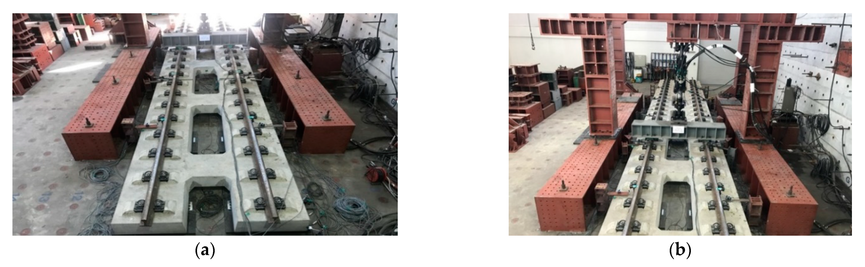
Figure 6 and
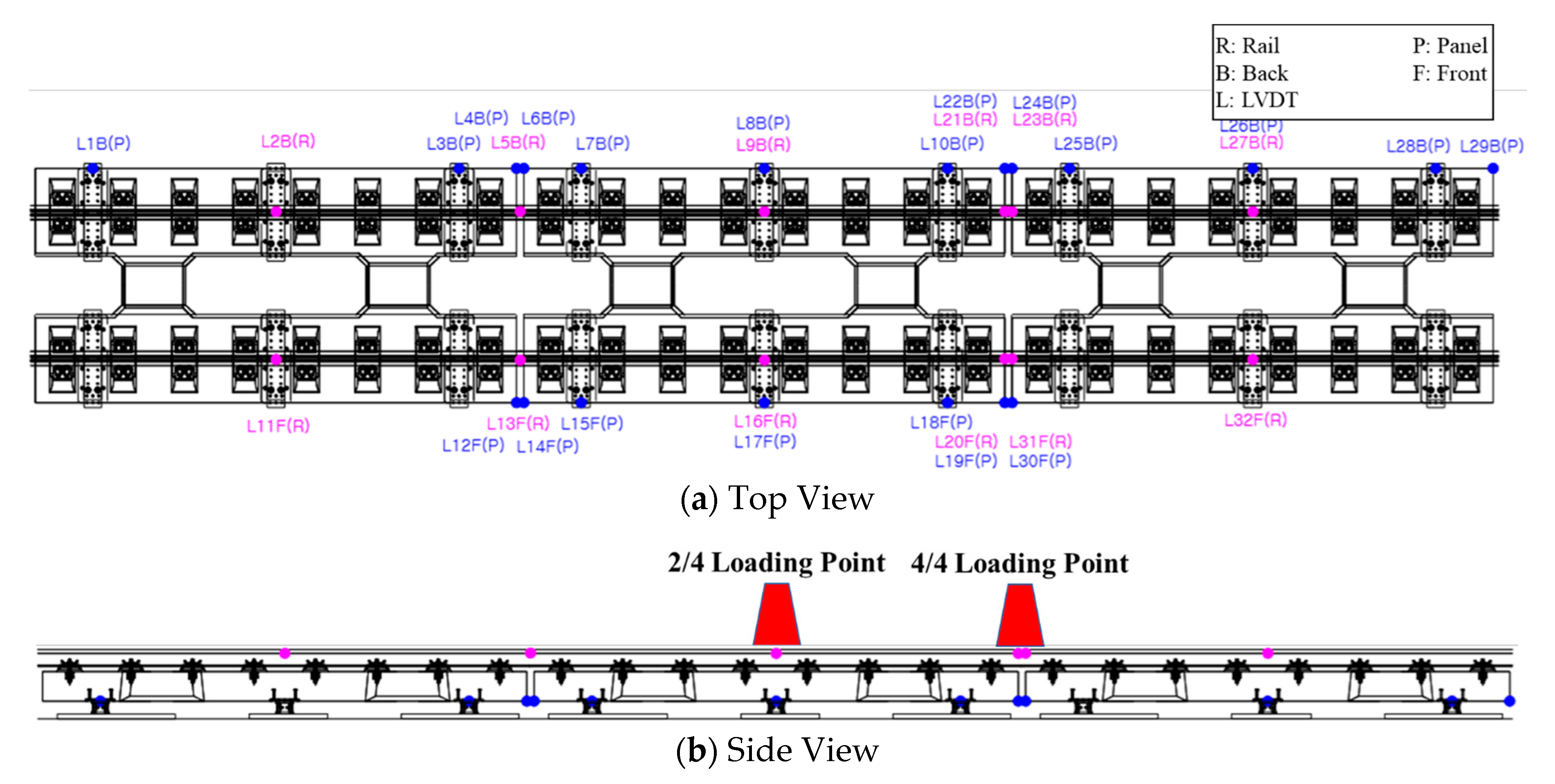
Figure 7. First, the anti-vibration devices were installed at the bottom of the panels. Next, the panels were fixed on the flat floor by screws, and finally, the load was applied at two load cases as mention above. The linear voltage differential transducers (LVDT) were set to 50 mm mounted on the rails; panels are shown in
Figure 7 to measure the behavior of structures. The load capacity was set to 500 kN using a dynamic actuator, and the data was collected using a TDS-601 data logger, which was manufactured by Tokyo Corp.
4. Numerical Analysis
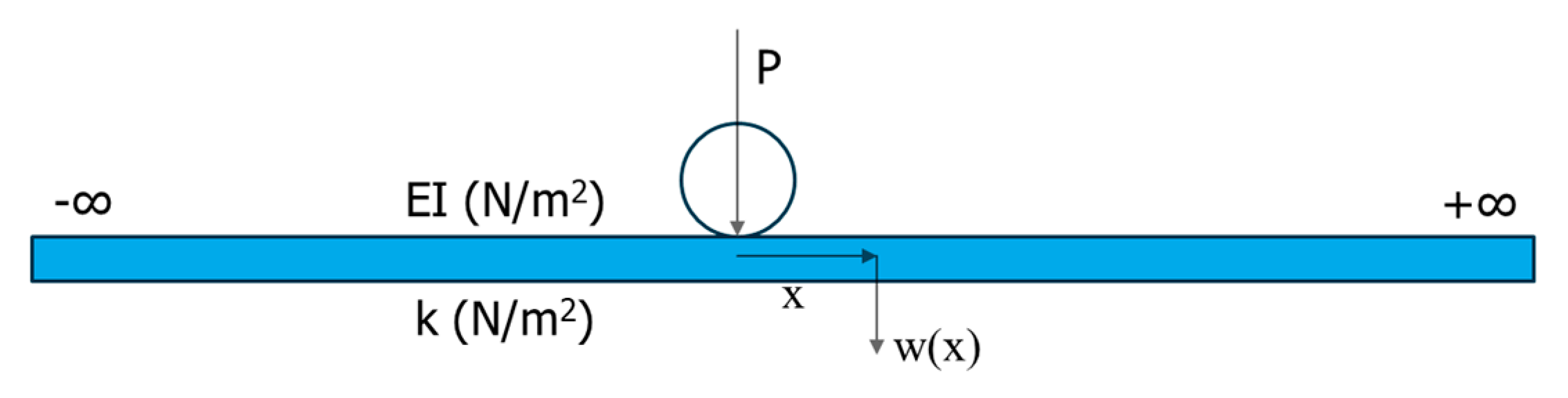
In railway application, according to the Zimmermann method which is the well-known “beam on elastic foundation”, the rail is assumed as a continuous beam supported by the elastic foundation system composed by fastening system, ballast, sub-ballast-mat as well as sub-soil. In this study, we focused on the displacement of the structures under the static loads to determine the load transfer efficiency of precast floating slab track. To model this type of precast floating slab track, based on this method, we considered the rail as a continuous beam mounted on the panels by fastening system and the panels (discontinuous slabs) was attached with the anti-vibration device as the elastic component.
According to the beam on elastic foundation theory, the deflection and moment of the beam under the concentrated wheel load shown in
Figure 8 can be calculated as following formulas:
where:
L: characteristic length
(m); and
kd: stiffness coefficient of discrete support
and ;
a: spacing between centers of discrete supports (m);
Q: wheel load (N) = 0.5 P (with P is axle load)
EI: bending stiffness of beam (N/m2);
and, two influence factors are:
This type of precast floating slab track was simulated as the double beam model with discrete support so the finite element method can be used to evaluate the structural behavior of the track [
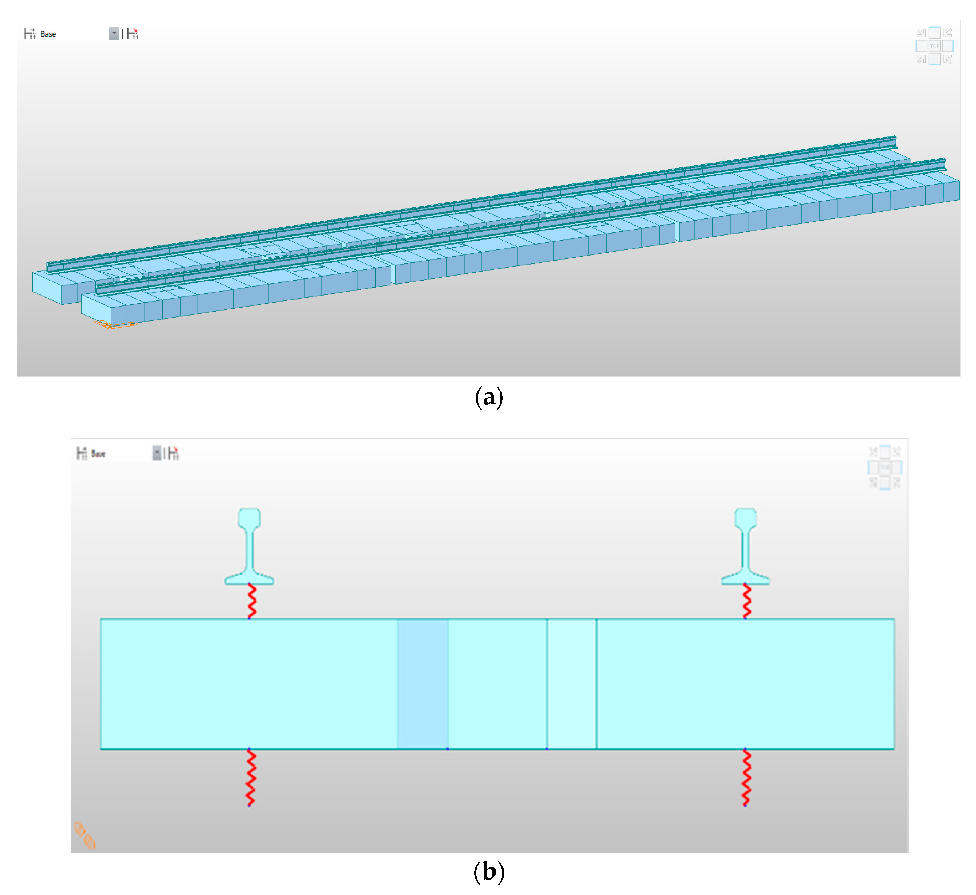
1]. In this paper, we used MIDAS CIVIL 2019, a finite element program to model the precast floating slab track. The continuous rail was modeled by using the profile of KR 60 rail, considered as a continuous beam and the standard gauge (1435 mm) was applied. The panel was modeled by two concrete slabs connected with each other by crossbeams using the beam element and the distance between each panel is 75 mm. The rail and concrete slab were connected by the elastic fastening system (system 300-1, KR type) with the vertical stiffness was 28.7 kN/mm. Six anti-vibration devices were set up at the bottom of each panel as the spring device (elastic link element), the vertical stiffness of each device was 22.5 kN/mm. The structure system analysis model and specifications are shown in
Figure 9 and
Table 3, respectively.
Figure 9 shows the concept of three panels (approximately 15 m length) simulated as the same dimensions of the actual specimens with the continuously rail mounted on by the fastening device. This new type of precast floating slab track has no joint to connect the panels, so the load can be distributed and transmitted directly through the rails.
5. Results and Discussion
This study conducted load tests to evaluate the displacement of the structures as well as the load transfer efficiency of the new type of precast floating slab track. The results of the test are compared with the Finite Element Analysis to accurately understand the structure behaviors.
5.1. Load Case I
In this Load case, the loads were set up at the center of 2nd panel to verify the maximum bearing capacity as well as the maximum deflection of the structures.
Table 4 shows the vertical displacement measurement results for the three-panel precast floating slab track, which was mounted on a 60 K continuous rail with a central loading point (2/4 loading point) compare with the FEA results.
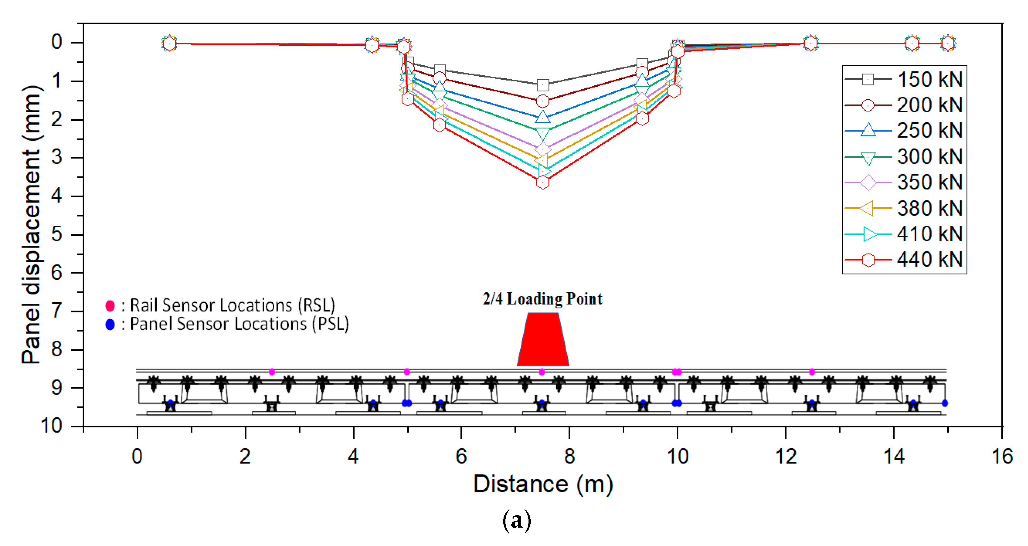
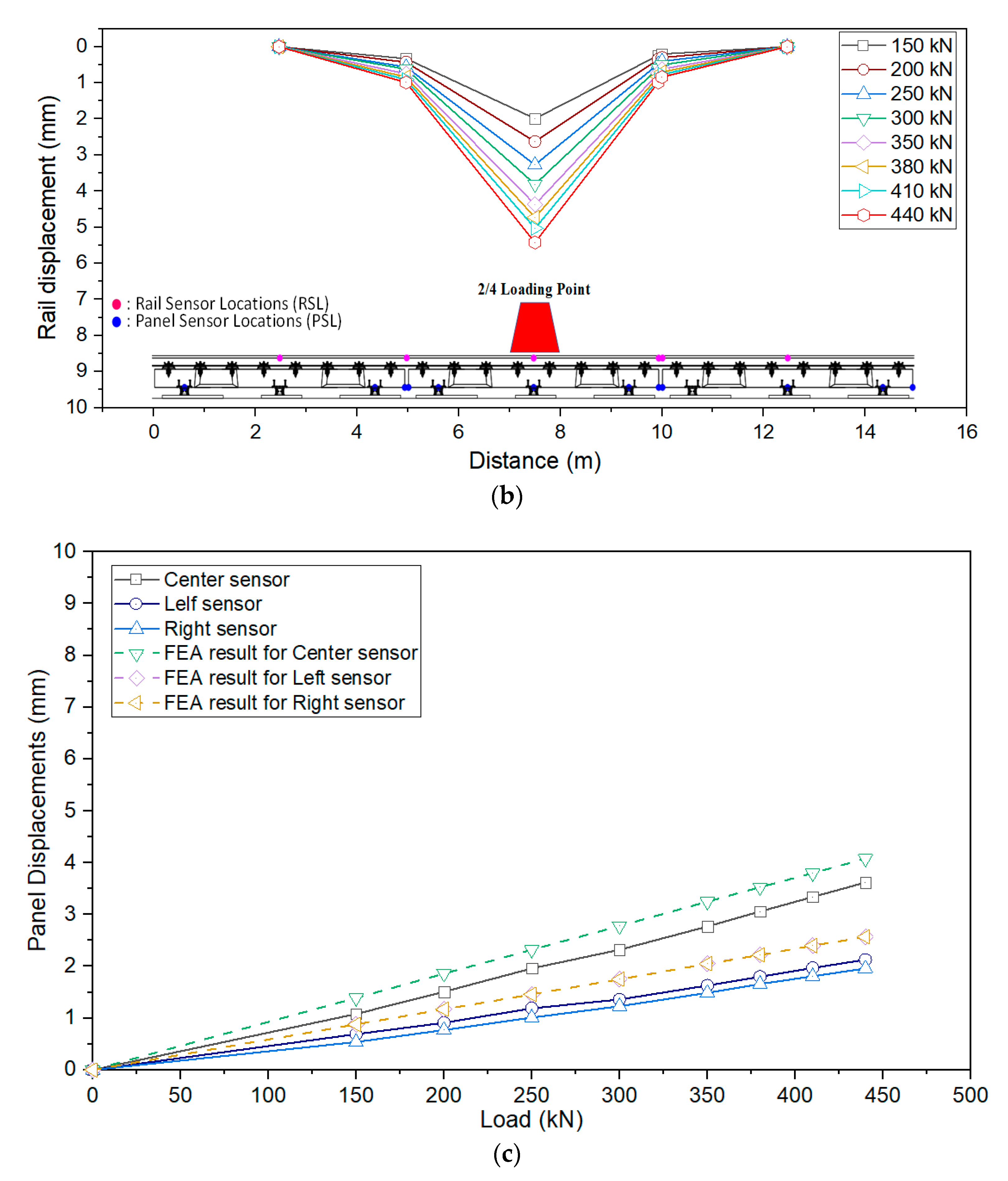
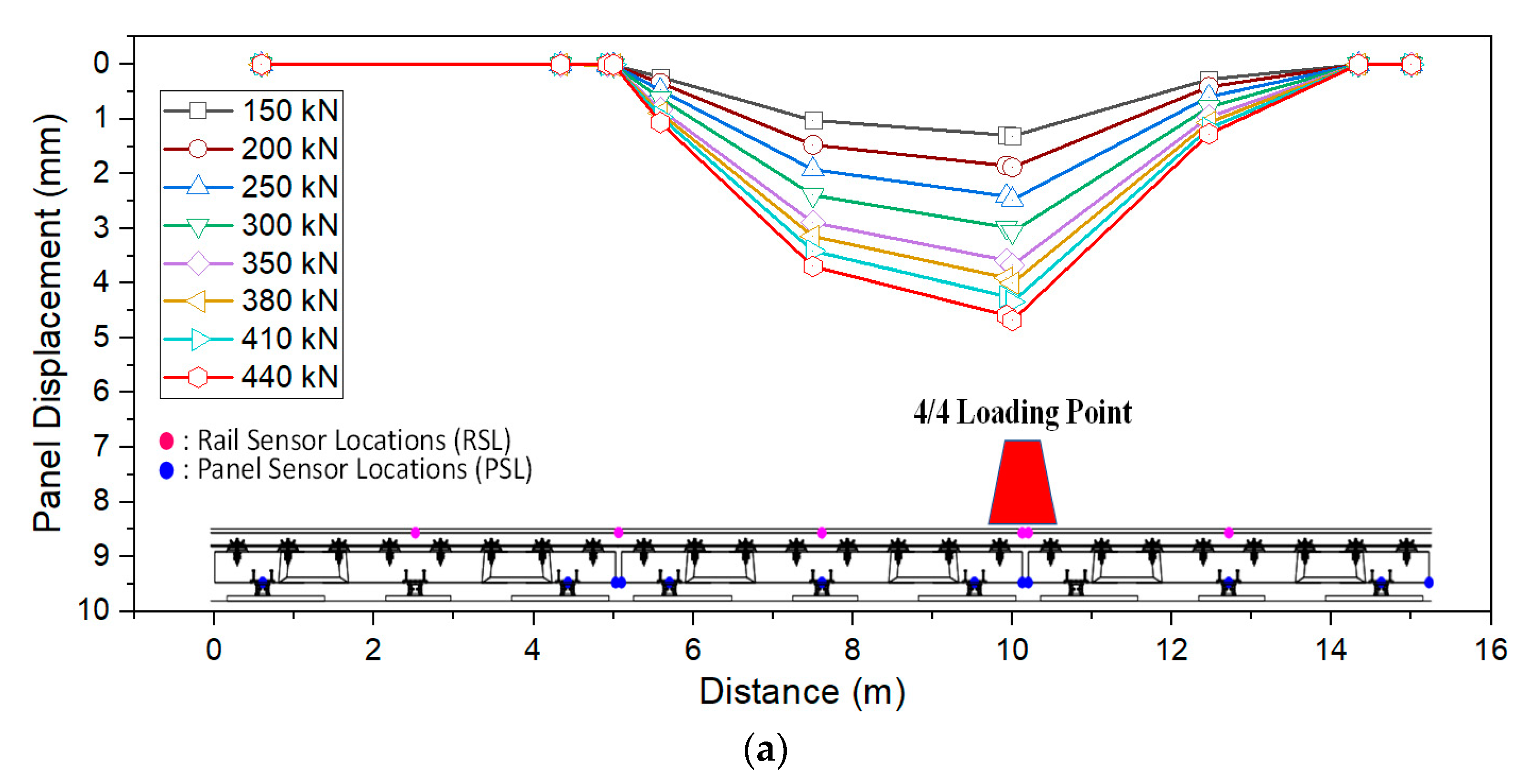
Figure 10 shows the vertical deflections of the panel, and the relative deflections of the right rail, which were measured in Load case I when applying loads in the center of the 2nd panel (2/4 loading point). As shown in
Figure 5a, under monotonic loads of 150 to 440 kN, the vertical displacement of the panel occurred between 1.08 to 3.62 mm, when the sensor was installed in the center of the panel. However, on the right-side sensor the displacement of panel changed from 0.54m to 1.96 mm and this data on the left-side was increased from 0.69 to 2.13 mm, so that the average vertical deflection value varied from 0.77 to 2.57 mm. This is because of the greater the load, the greater the vertical displacement. The estimated support stiffness of the six anti-vibration devices under the slab was calculated by divided the load by the average deflection and determined to be 28.53–32.47 kN/mm, which is slightly bigger than the value of the original design. Due to the load was applied in the center of three panels, the displacement of the panels in
Figure 10a and the displacement of the rails in
Figure 10b can be compared with others. As can be seen in
Figure 10a,b, the loads were transmitted and distributed to three panels through the rails. However, even if the loads from 150~440 kN were applied in the 2nd panel, the vertical displacement only occurred in the central panel and this value of the left and right panel was exceedingly small. This situation was also the same for rail displacement.
As can be seen in
Figure 10c, the results from the assembly test were moderately smaller than the FEA results. The panel displacements at the left and right sensors were similar according to the calculation of the program. The maximum average value of FEA was roughly 1.2 times larger than this value from the actual test. Moreover, the support stiffness was measure around 23.8 kN/mm from the program which was almost the same as the design stiffness of the anti-vibration device (22.5 kN/mm).
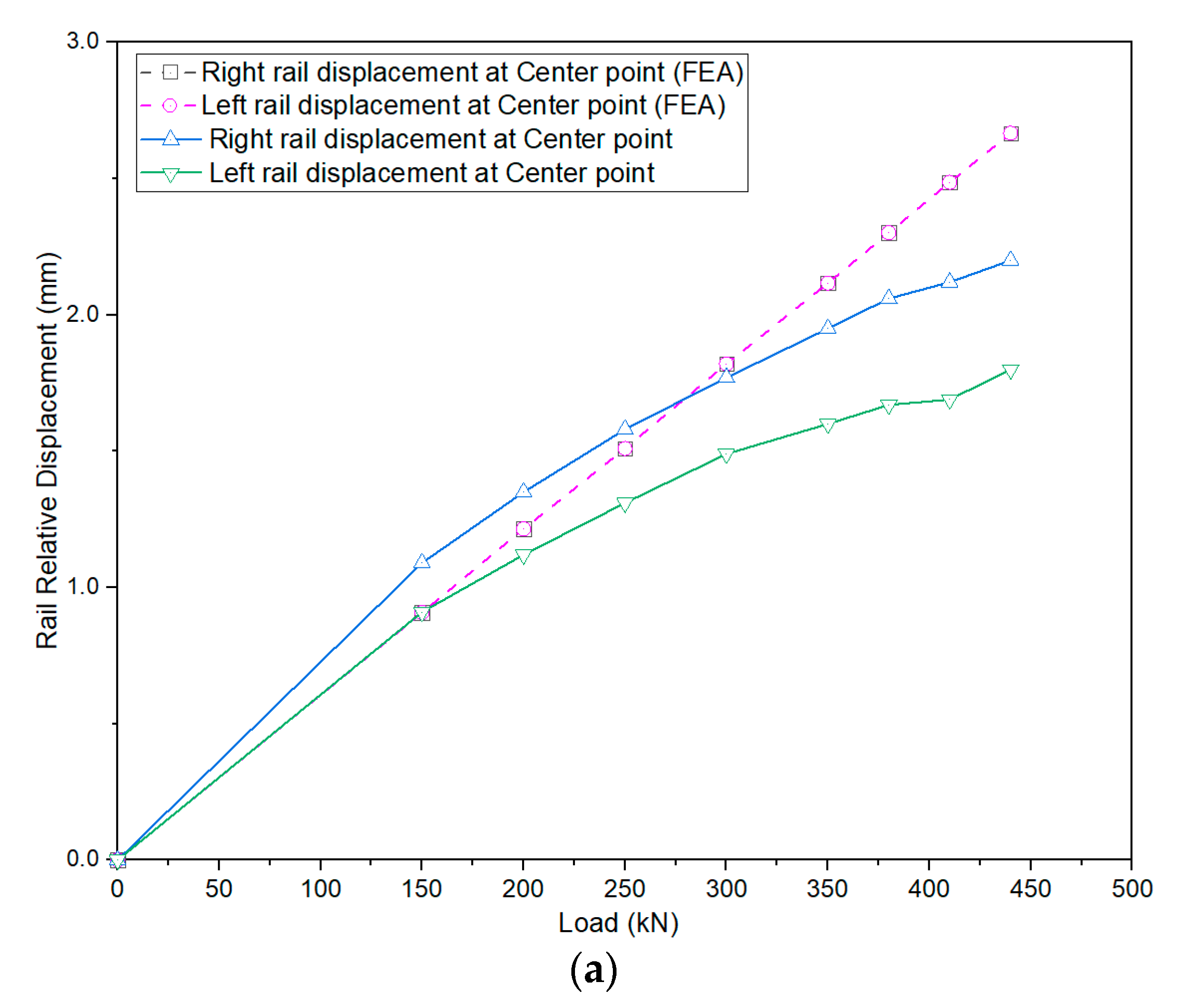
Table 5 shows the results for the relative rail vertical deflections at both the center endpoints. These deflections occurred in both rails when the load was applied in the center of the 2nd panel. This result was calculated by the difference between the deflection of rail and panel. The displacements in the left and right rails were almost insignificant. The maximum displacement of the relative rail to be 2.2 mm, which was 440 kN for the 60K rail mounted on three-panel assembly test. At the center point, the vertical relative displacement of the right rail was 0.91 to 1.80 mm. However, the left rail was between 1.09 to 2.20 mm. The maximum displacement deviation of the left and right sides was 0.43 mm. Under the same loading conditions, the vertical deflection of the left rail at the endpoint was 0.06 to 0.39 mm, and 0.10 to 0.25 mm for the right rail. Thus, the average displacement of the rails mounted on three-panel at the center point was approximately 8.30 times larger than at the endpoint.
As can be seen in
Figure 11, the FEA results present the relative displacements of both rails have no difference at center point or endpoint. The displacement of both rails at the center point was 0.91–2.67 mm, and this value at the endpoint was 0.16–0.48 mm. The average deflection of rails at the center point when calculated by the FEM program was only 5.61 times larger than at the endpoint. When comparing the maximum average results, the experiment test value was 0.93 times of finite element analysis result.
5.2. Load Case II
Figure 12 shows the results when the loads were applied to the 2nd panel at 4/4 loading points (Load case II). The main reason of this Load case is to determine the effectiveness of transferring the load from one panel to another. The loading point was set up at the junction between two panel (2nd and 3rd panel). The loads were transmitted between two panel without any dowel bar or connection joint.
The previous research about concrete pavement pointed out that at least 10% of initial cost increase if install the dowel bars between the panel [
21,
22]. To limit that issue, this precast floating slab track used rails to transfer the load from the panels and the distance between each slab was 75 mm. In this type of track, the upper part of the panel was fastened only by the rails, which were separated from the track slab. Because the train runs on these rails, it is necessary to consider the relative deflection of the connected panel. If a difference occurs in the upper part of the panel of the relative deflection of the rail, then the railway train will affect the dynamic behavior, such as the vehicle acceleration, and body acceleration will increase due to a step difference that occurs when the train passes through the connected portion [
23]. The vertical deflection of the panel and the rail at the endpoint and the adjacent point were therefore measured.
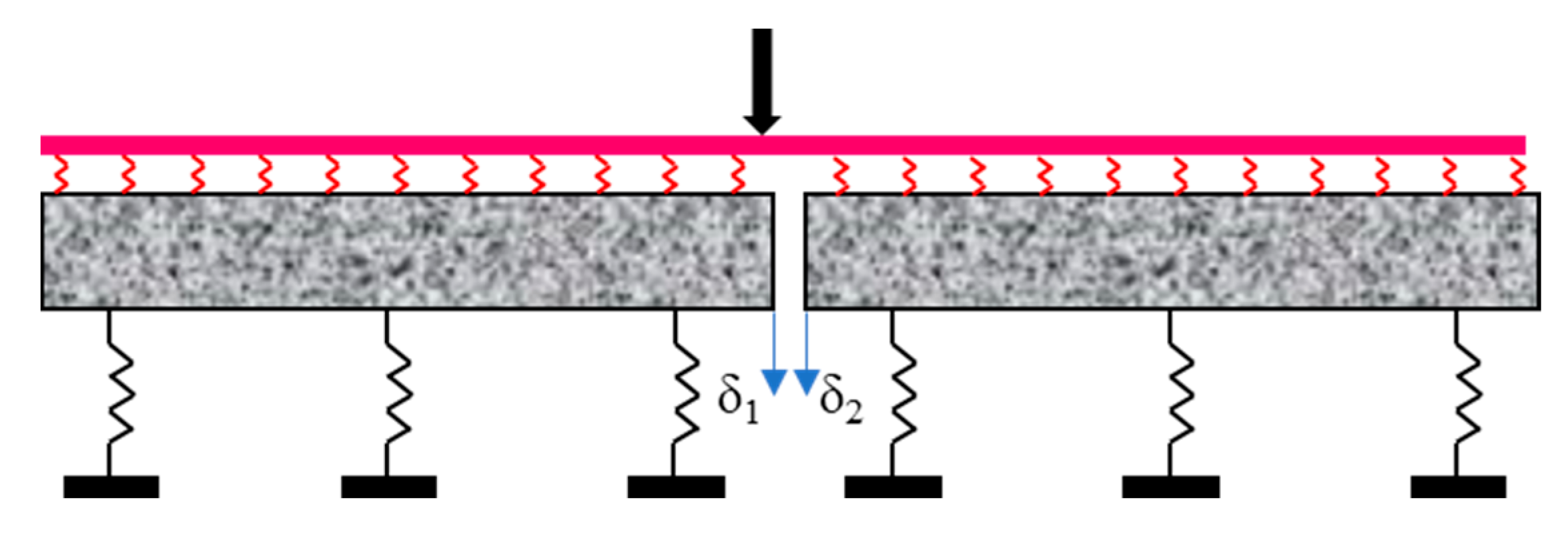
The load transfer characteristics of the slab panel connection can be determined by using load transfer efficiency (LTE), which is defined as by [
24]:
where, δ
1: is the rail/panel displacement at panel endpoint (mm).
δ2: is the rail/panel displacement at panel adjacent point (mm).
As shown in
Figure 13, the load transfer efficiency (LTE) of this precast floating track was based on the displacement of rail and panel between the loaded panel endpoint (δ
1) and unloaded panel adjacent point (δ
2). In this paper, the precast floating track has used the rails mounted on the slabs to transfer the load from one slab to another instead of the connection joint or dowel. If the displacement of loaded slab panel approximated with the unloaded one (δ
1 ≈ δ
2), the result in LTE will reach 100% [
22]. High stresses will occur if the load transfer is poor and it may cause the pumping, faulting and breaks at the corner. Therefore, load transfer efficiency is especially important to ensure the running safety of floating slab track.
The evaluated results are shown in
Table 6 and
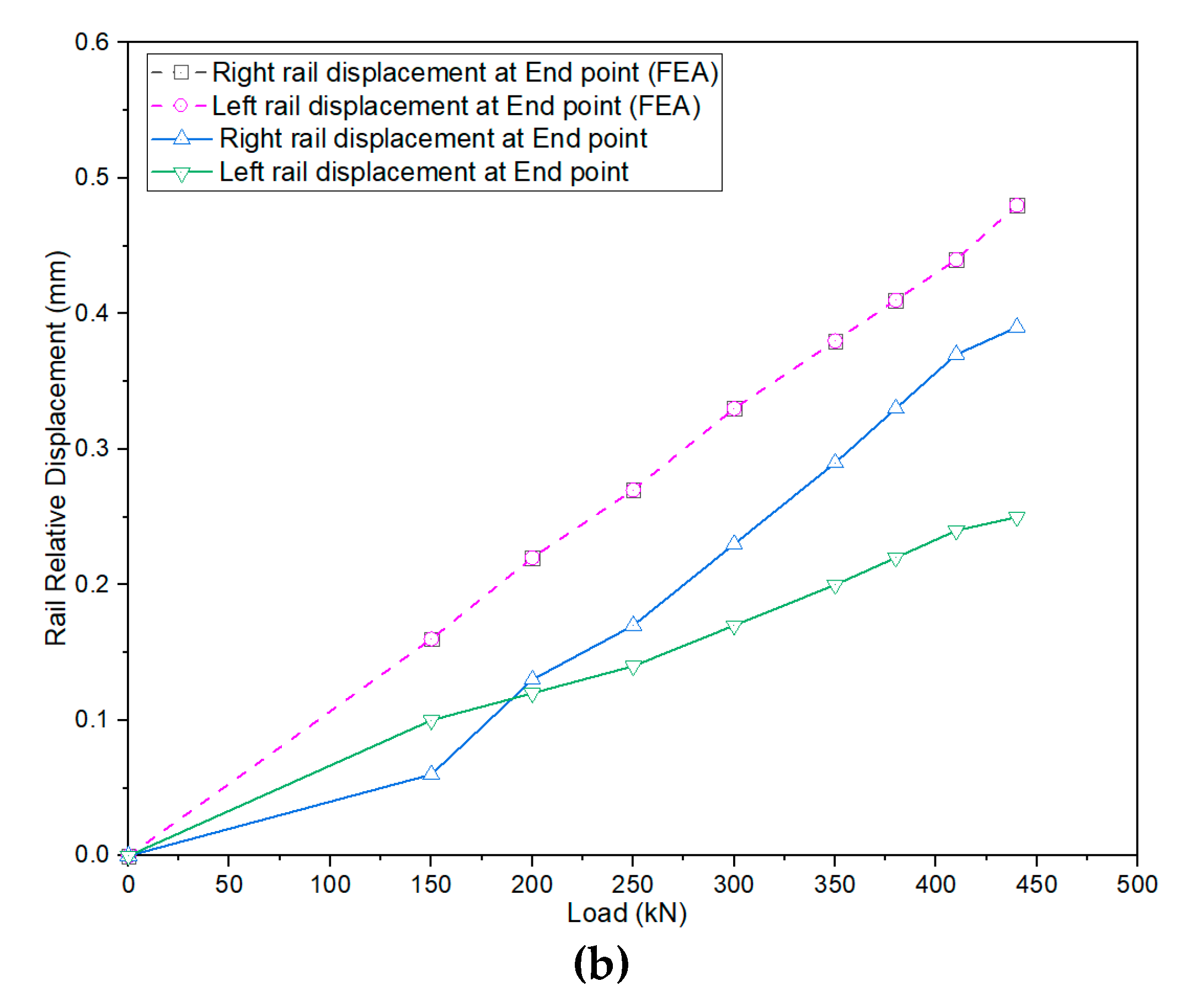
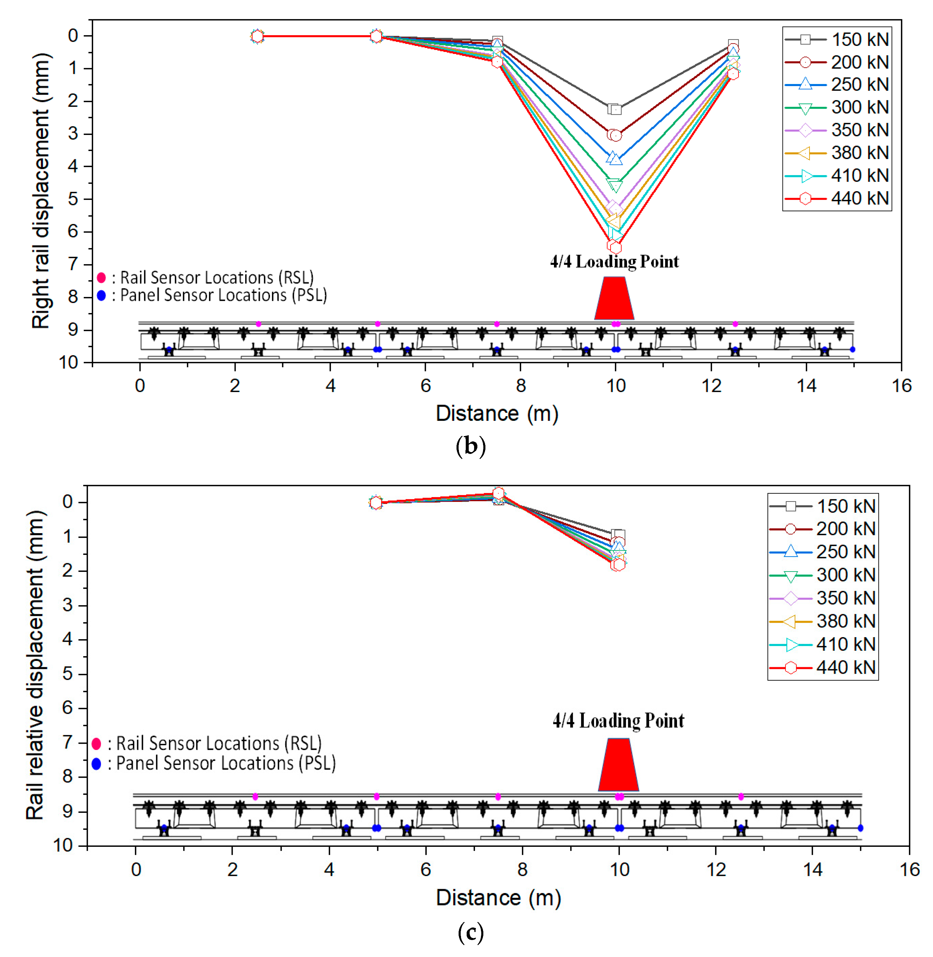
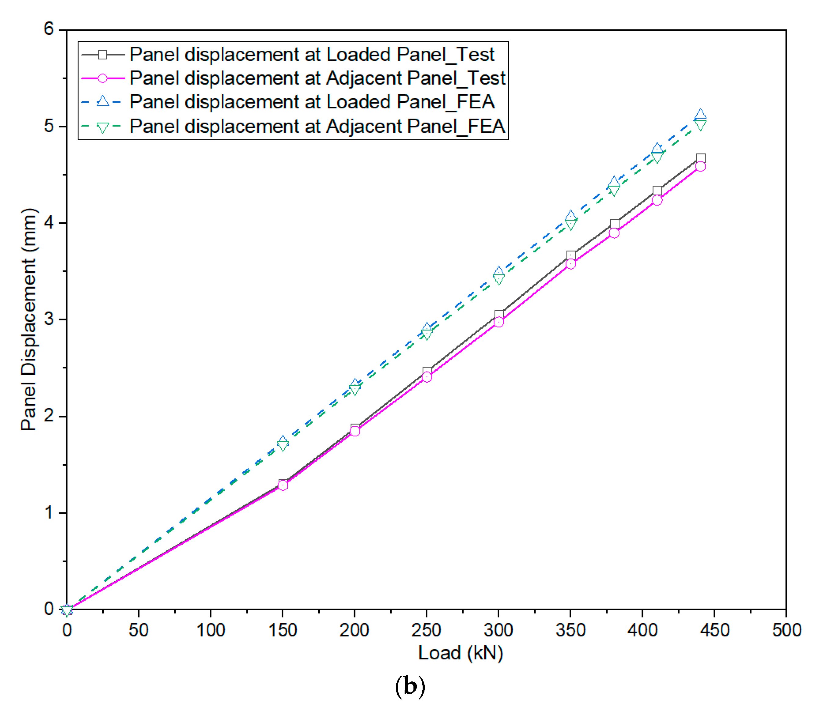
Table 7. According to the measurements, when a load of 150 to 440 kN was applied at Load case II, rail deflection was 2.24 to 6.48 mm at the panel’s endpoint and was 2.21 to 6.4 mm in the adjacent panel. Meanwhile, the displacement of the panel was 1.31 to 4.68 at the loaded panel and was 1.29 to 4.59 at the adjacent one. However, these values of rail and panel which were calculated by FEA was slightly larger as shown in
Figure 14. Based on the 250 kN load of Korea’s standardized cargo design load, the rail deflections difference between the ends was 0.08 mm and the panel deflection difference between the ends was 0.06 mm, which was within 2 mm of the Japanese usability standard for high-speed railway bridges. When the track slab separation distance was 75 mm, the inclination of rail was a maximum of 1.2‰, which is less than the standard of comfort (2.5 ‰) as well as the safety standard (2.0‰) in Japan.
As mention above, the purpose when applying the loads at Load case II is to verify the efficiency of the load transmitted between panels. From the data of the test and program, the LTE results from the assembly test were smaller than FEA. The evaluated LTE of rail at maximum load (440 kN) was 99.38%, and this value from FEA was 99.84% with a relative difference of 0.46%. Moreover, the error in the panel was 1.05% in the same condition. However, these results show that this type of track can transfer the load perfectly with various kinds of load (150–440 kN) with the LTE more than 99% for the rail and 97% for the panel.
Table 8 presents comparisons of the average load transfer efficiency and numerical method (Midas civil program). The results show that the LTE from FEA was slightly larger and equal to 1.01 times compared with the experiment.
In terms of structural safety and ride comfort, the step standard is presented in the design guidelines of the Korea Railroad Authority “Honam High-speed Rail Design Guidelines (Civil Work)” [
25], and the design standards such as the Japanese railway structures Displacement Limitation [
26], and the European standards. In this case, the Japanese standard was used for the concrete slab track. The average LTE of the rail was 99.24%, and the panel was 98.90%. The precast floating track does not have a load-carrying structure, such as a dowel, which connects the track slabs directly to each other. However, load transfer occurred through the rails (60 K rails), which were fastened at the top of the panel.
6. Conclusions
We developed and designed a new type of precast floating slab track structure, which differs from conventional track structures. The main purpose of this type of track is to reduce the ground-borne noise and vibration generated from the vehicle–track interaction. As part of this study, the floating track was assessed using experimental methods, and this type of track were simulated by using MIDAS Civil 2019—a finite element analysis to calculate the structural performance base on the beam on elastic foundation theory. Moreover, before operating the train, a precast floating track structure was assembled after installing the slab panel with the anti-vibration devices, which were manufactured in a factory and mounted on a continuous rail using a fastening device. As the train passed through, we determined that the track structure behavior was similar to the structural assembly test. After testing and comparing with the results of the FEA, the following conclusions were drawn. First, the measured vertical deflection of the rails and the panels of the structural assembly of the test specimen composed of the three-panel, satisfied the requirements of the track (rail relative displacement ≤ 3 mm). Therefore, the design can be considered sufficiently safe. The performance of the track was verified through experimental loading tests. Both the center point and end points of the three panels, which were joined by a rail, exhibited vertical rail deflections satisfied the requirements. The average panel vertical displacement of three-panel by FEM program was 1.2 times greater than the result from assembly test. Meanwhile, the maximum rail displacement from FEA was roughly 1.1 times larger than from the test. Therefore, the train loads were distributed to the adjacent precast floating track through the continuous rail. The reason of these differences can be explained that the average supported stiffness from experimental results was larger than FEA results. Moreover, when applying the assembly test, errors might be occurred that could lead to these differences.
Instead of steel plate or steel bar as the dowel joints, the loads were transmitted directly between the slab panels by continuous rail (60 K rail). When trainloads were applied to the rails, a difference in the rail displacement (step difference) and the LTE was measured at the end of the panels. From these results, we found that a step difference in the rails and panels was within the standard limit (2 mm), and the structure was secure during train operations. In addition, the average LTE of the rails was 99.24%, and the panel was 98.90% when measured during train operations. So, this precast floating slab track can secure the trainloads which were sufficiently transmitted through the structures.
Author Contributions
Conceptualization, L.V.; methodology, L.V. and Y.S.K.; software, L.V.; validation, L.V. and Y.S.K.; formal analysis, L.V.; investigation, L.V.; resources, L.V. and Y.S.K.; data curation, L.V.; writing—original draft preparation, L.V.; writing—review and editing, L.V. and Y.S.K.; visualization, L.V. and Y.S.K.; supervision, Y.S.K.; project administration, Y.S.K.; funding acquisition Y.S.K. All authors have read and agreed to the published version of the manuscript.
Funding
This research was funded by the railway technology research project (19RTRP-C148760-02) by the Korea Agency for Infrastructure Technology Advancement.
Institutional Review Board Statement
Not applicable.
Informed Consent Statement
Not applicable.
Data Availability Statement
The data presented in this study are available on request from the corresponding author.
Conflicts of Interest
The authors declare no conflict of interest.
References
- Esveld, C. Modern Railway Track, 2nd ed.; Delft University of Technology: Zaltbommel, The Netherland, 2001. [Google Scholar]
- Birhane, F.N.; Choi, Y.T.; Lee, S.J. Development of GPR Device and Analysis Method to Detect Thickness of Ballast Layer. J. Korean Soc. Railw. 2020, 23, 269–278. [Google Scholar] [CrossRef]
- Koh, T.; Shin, M. Field Tests on Eco-Friendly Railway Precast Concrete Slab. Appl. Sci. 2020, 10, 4140. [Google Scholar] [CrossRef]
- Pichler, D. Ballastless Track Systems Experiences Gained in Austria and Germany. In Proceedings of the AREMA Conference, Indianapolis, IN, USA, 29 September–2 October 2013; pp. 81–100. [Google Scholar]
- Kwon, S.G.; Kim, J.Y. Development of noise and vibration reduction technology for railway station structures. Railw. J. Korean Soc. Railw. 2018, 21, 14–20. [Google Scholar]
- Yang, S.C.; Kang, Y.S.; Kim, M.C. Evaluation method for vibration-reduction efficiency of slab track. J. Korean Soc. Civ. Eng. 2000, 20, 427–435. [Google Scholar]
- Yang, S.C.; Kim, T.W.; Kang, Y.S. Measures for noise and vibration of high speed railway track structures. J. Korean Soc. Noise Vib. Eng. 2004, 14, 26–34. [Google Scholar]
- Li, Z.G.; Wu, T.X. On vehicle/track impact at connection between a floating slab and ballasted track and floating slab track’s effectiveness of force isolation. Veh. Syst. Dyn. 2009, 47, 513–531. [Google Scholar] [CrossRef]
- Wagner, H.G. Attenuation of Transmission of Vibrations and Ground-Borne Noise by Means of Steel Spring Supported Low-Tuned Floating Track-Beds. In Proceedings of the 2002 World Metro Symposium, Taipei, Taiwan, 25–27 April 2002. [Google Scholar]
- Jin, H.; Liu, W.; Zhou, S. An experiment to assess vibration reduction ability of the rubber floating-slab tracks with different supporting forms. J. Vibroeng. 2015, 17, 3237–3246. [Google Scholar]
- Kang, Y.S. Performance Improvement and Maintenance Technology Development of High-Speed Railway Systems—Next Generation High Speed Rail Technology Development Project; Final Report; Korea Railroad Research Institute, Ministry of Land, Infrastructure and Transport: Gyeonggi-do, Korea, 2012.
- Cui, F.; Chew, C.H. The effectiveness of floating slab track system—Part I. Receptance methods. Appl. Acoust. 2000, 61, 441–453. [Google Scholar] [CrossRef]
- Grootenhuis, P. Floating track slab isolation for railways. J. Sound Vib. 1977, 51, 443–448. [Google Scholar] [CrossRef]
- Hui, C.; Ng, C. The effects of floating slab bending resonances on the vibration isolation of rail viaduct. Appl. Acoust. 2009, 70, 830–844. [Google Scholar] [CrossRef]
- Lombaert, G.; Degrande, G.; Vanhauwere, B.; Vandeborght, B.; François, S. The control of ground-borne vibrations from railway traffic by means of continuous floating slabs. J. Sound Vib. 2006, 297, 946–961. [Google Scholar] [CrossRef]
- Nelson, J. Recent developments in ground-borne noise and vibration control. J. Sound Vib. 1996, 193, 367–376. [Google Scholar] [CrossRef]
- Wagner, H.-G.; Herrmann, A. Floating Slab Track Above Ground for Turnouts in Tram Lines. In Proceedings of the 9th International Workshop on Railway Noise, Munich, Germany, 4–8 September 2007; pp. 86–93. [Google Scholar]
- Yuan, J.; Chang, Y.; Meng, Z.; Song, L. Modal Analysis and Parameter Assessment of Floating Slab Track. In Proceedings of the International Conference on Transportation Engineering, Chengdu, China, 25–27 July 2009; p. 543. [Google Scholar]
- Montella, G.; Mastroianni, G.; Serino, G. Experimental and Numertical Investigations on Innovative Floating—Slab Track Including Recycled Rubber Elements. In Proceedings of the 25th International Conference on Noise and Vibration Engineering (ISMA 2012), Leuven, Belgium, 17–19 September 2012. [Google Scholar]
- Kang, Y.S.; Lee, C.Y.; Du Jang, D.; Kwon, S.G.; Han, W.J.; Vu, L. Study on Structural Performance of Precast Track of Discrete Panel Supporting Type for Rapid Ballast Improvement. J. Korean Soc. Hazard Mitig. 2020, 20, 233–244. [Google Scholar] [CrossRef]
- Smith, K.D.; Peshkin, D.G.; Darter, M.I.; Mueller, A.L.; Carpenter, S.H. Performance of Jointed Concrete Pavements, Volume I: Evaluation of Concrete Pavement Performance and Design Features; FHWA-RD-89-136; Federal Highway Administration: McLean, VA, USA, 1990.
- Chung, W.; Kwon, K.; Jang, S.Y. Deflection-based load transfer efficiency of Floating Slab Track. KSCE J. Civ. Eng. 2014, 18, 616–624. [Google Scholar] [CrossRef]
- Jang, S.-Y.; Yang, S.-C. Assessment of Train Running Safety, Ride Comfort and Track Serviceability at Transition between Floating Slab Track and Conventional Concrete Track. J. Korean Soc. Railw. 2012, 15, 48–61. [Google Scholar] [CrossRef][Green Version]
- Jang, S.Y.; Ahn, M.K.; Choi, W.I.; Park, M.H. Investigation of Load Transfer Characteristics at Slab Joints in the Floating Slab Track by Equivalent Shear Spring Model. In Proceedings of the 2011 Autumn Conference, Jeju, Korea, 20–22 October 2011; pp. 2838–2843. [Google Scholar]
- Korea Railroad Network Authority. Honam High-Speed Rail Design Guidelines; Civil Work; Korea Railroad Network Authority: Seoul, Korea, 2007. [Google Scholar]
- Railway Technology Research Institute (RTRI). Design Standards for Railway Structures and Commentary—Limit for Displacement; Ministry of Land, Infrastructure, Transport, and Tourism: Tokyo, Japan, 2007.
Figure 1.
The structural vibration transfer path.
Figure 1.
The structural vibration transfer path.
Figure 2.
Single degree of freedom scheme.
Figure 2.
Single degree of freedom scheme.
Figure 3.
(a) Three-dimensional (3D)-modeling of the precast floating panel, and (b) cross-section of precast floating panel.
Figure 3.
(a) Three-dimensional (3D)-modeling of the precast floating panel, and (b) cross-section of precast floating panel.
Figure 4.
Fabrication process of precast floating panel: (a) assembly of rebar, (b) concrete pouring, (c) curing, and (d) prototype of precast floating panels.
Figure 4.
Fabrication process of precast floating panel: (a) assembly of rebar, (b) concrete pouring, (c) curing, and (d) prototype of precast floating panels.
Figure 5.
Assembly test specifications: (a) full scale static loading diagram and (b) installation of assembly test.
Figure 5.
Assembly test specifications: (a) full scale static loading diagram and (b) installation of assembly test.
Figure 6.
Structural assembly of three slab panel with 60 K rail: (a) Load case I: center loading point, and (b) Load case II: 2nd panel at 4/4 loading point test.
Figure 6.
Structural assembly of three slab panel with 60 K rail: (a) Load case I: center loading point, and (b) Load case II: 2nd panel at 4/4 loading point test.
Figure 7.
Locations of sensors to evaluate the performance of the three precast panels.
Figure 7.
Locations of sensors to evaluate the performance of the three precast panels.
Figure 8.
Beam on elastic foundation model.
Figure 8.
Beam on elastic foundation model.
Figure 9.
Modeling of the precast floating slab; (a) overview, and (b) front view.
Figure 9.
Modeling of the precast floating slab; (a) overview, and (b) front view.
Figure 10.
Three-panel vertical displacement test results (Load case I) (a) vertical displacement of the panel (mm), (b) rail vertical displacement (mm), and (c) comparison between FEA and test results (mm).
Figure 10.
Three-panel vertical displacement test results (Load case I) (a) vertical displacement of the panel (mm), (b) rail vertical displacement (mm), and (c) comparison between FEA and test results (mm).
Figure 11.
Comparison of rail relative displacement (Load case I), (a) at center point, and (b) at end point.
Figure 11.
Comparison of rail relative displacement (Load case I), (a) at center point, and (b) at end point.
Figure 12.
Vertical displacement results for three-panel testing (at 2nd panel 4/4 loading point), (a) vertical displacement of the panel (mm), (b) vertical displacement of the right rail (mm), and (c) rail relative vertical displacement (mm).
Figure 12.
Vertical displacement results for three-panel testing (at 2nd panel 4/4 loading point), (a) vertical displacement of the panel (mm), (b) vertical displacement of the right rail (mm), and (c) rail relative vertical displacement (mm).
Figure 13.
Load transfer between slab panel.
Figure 13.
Load transfer between slab panel.
Figure 14.
Load-displacement results of assembly test and finite element analysis (Load Case II), (a) vertical displacement of the right rail (mm), and (b) vertical displacement of the panel (mm).
Figure 14.
Load-displacement results of assembly test and finite element analysis (Load Case II), (a) vertical displacement of the right rail (mm), and (b) vertical displacement of the panel (mm).
Table 1.
Specification of Specimen.
Table 1.
Specification of Specimen.
| Specifications | Dimensions |
|---|
| Size of Panel (m) | 4.925 (L) × 2.4 (W) × 0.3 (H) |
| Concrete Strength (MPa) | 45 |
| Weight of Panel (ton) | 7.6 |
| Vertical Support Stiffness of Anti-vibration Device (kN/mm) | 22.5 |
| Lateral Support Stiffness of Anti-vibration Device (kN/mm) | 18 |
Table 2.
Loading points.
| Classification | Loading Point | Steps |
|---|
| Number of Panel | Loading Cases |
|---|
| Three Panels | Load case I | Load on 2nd panel-2/4 Point
(Distance: 7.4625 m load on both rails) | 8 Steps (150–440 kN) |
| Load case II | Load on 2nd panel-4/4 Point
(Distance: 10.00 m load on both rails) | 8 Steps (150–440 kN) |
Table 3.
Specification of track system.
Table 3.
Specification of track system.
| Classification | Unit | Specification |
|---|
Rail
(KR60) | Moment of inertia | mm4 | 30,640,000 |
| Section modulus | mm3 | 395,000 |
| Modulus of elasticity | MPa | 210,000 |
| Coefficient of thermal expansion | 1/°C | 1.14 × 10⁻⁵ |
| Fastening system | Type | | System 300-1 |
| Width | mm | 160 |
| Length | mm | 290 |
| Static stiffness (Vertical direction) | kN/m | 28,734 |
| Dynamic stiffness (Vertical direction) | kN/m | 32,770 |
| Static stiffness (Lateral direction) | kN/m | 40 |
| Dynamic stiffness (Lateral direction) | kN/m | 60 |
| Precast concrete slab (ladder type) | Thickness | mm | 300 |
| Width | mm | 900 |
| Length | mm | 4925 |
| Modulus of elasticity | MPa | 35,684 |
| Compressive strength | MPa | 45 |
| Poison’s coefficient | - | 0.18 |
| Coefficient of thermal expansion | 1/°C | 1.0 × 10⁻⁵ |
| Anti-vibration device | Static stiffness | kN/m | 22,500 |
| Stability stiffness (longitudinal direction) | kN/m | 18,000 |
| Stability stiffness (lateral direction) | kN/m | 18,000 |
| Crossbeam | Modulus of elasticity | MPa | 35,684 |
| Compressive strength | MPa | 45 |
| Poison’s coefficient | - | 0.18 |
| Coefficient of thermal expansion | 1/°C | 1.0 × 10⁻⁵ |
Table 4.
Panel vertical displacement of three-panel precast floating slab track panel (central loading point in 2nd Panel).
Table 4.
Panel vertical displacement of three-panel precast floating slab track panel (central loading point in 2nd Panel).
Load
(kN) | Panel Vertical Displacement | Support Stiffness (kN/mm) | FEA Results for Panel Vertical Displacement |
|---|
Center Sensor
(mm) | Left Side Sensor (mm) | Right Side Sensor (mm) | Average Value
(mm) | Center Sensor
(mm) | Left Side Sensor
(mm) | Right Side Sensor
(mm) | Average Value
(mm) |
|---|
| 150 | 1.08 | 0.69 | 0.54 | 0.77 | 32.47 | 1.39 | 0.88 | 0.88 | 1.05 |
| 200 | 1.51 | 0.91 | 0.77 | 1.06 | 31.35 | 1.86 | 1.17 | 1.17 | 1.40 |
| 250 | 1.96 | 1.19 | 1.01 | 1.39 | 30.05 | 2.32 | 1.46 | 1.46 | 1.75 |
| 300 | 2.32 | 1.36 | 1.23 | 1.64 | 30.55 | 2.78 | 1.75 | 1.75 | 2.09 |
| 350 | 2.77 | 1.63 | 1.49 | 1.96 | 29.71 | 3.25 | 2.05 | 2.05 | 2.45 |
| 380 | 3.06 | 1.80 | 1.66 | 2.17 | 29.14 | 3.53 | 2.22 | 2.22 | 2.66 |
| 410 | 3.34 | 1.97 | 1.81 | 2.37 | 28.79 | 3.80 | 2.40 | 2.40 | 2.87 |
| 440 | 3.62 | 2.13 | 1.96 | 2.57 | 28.53 | 4.08 | 2.57 | 2.57 | 3.07 |
Table 5.
Maximum relative rail displacement results for the three-panel precast floating slab track (loading at center point of 2nd Panel).
Table 5.
Maximum relative rail displacement results for the three-panel precast floating slab track (loading at center point of 2nd Panel).
Load
(kN) | Center Point (mm) | End Point (mm) | FEA Results |
|---|
| Center Point (mm) | End Point (mm) |
|---|
| Left Rail | Right Rail | Left Rail | Right Rail | Left Rail | Right Rail | Left Rail | Right Rail |
|---|
| 150 | 1.09 | 0.91 | 0.06 | 0.10 | 0.91 | 0.91 | 0.16 | 0.16 |
| 200 | 1.35 | 1.12 | 0.13 | 0.12 | 1.22 | 1.22 | 0.22 | 0.22 |
| 250 | 1.58 | 1.31 | 0.17 | 0.14 | 1.51 | 1.51 | 0.27 | 0.27 |
| 300 | 1.77 | 1.49 | 0.23 | 0.17 | 1.82 | 1.82 | 0.33 | 0.33 |
| 350 | 1.95 | 1.60 | 0.29 | 0.20 | 2.12 | 2.12 | 0.38 | 0.38 |
| 380 | 2.06 | 1.67 | 0.33 | 0.22 | 2.30 | 2.30 | 0.41 | 0.41 |
| 410 | 2.12 | 1.69 | 0.37 | 0.24 | 2.49 | 2.49 | 0.44 | 0.44 |
| 440 | 2.20 | 1.80 | 0.39 | 0.25 | 2.67 | 2.67 | 0.48 | 0.48 |
Table 6.
Load transfer efficiency (LTE) of rail between panel endpoint and panel adjacent (Load at 2nd panel 4/4 loading point).
Table 6.
Load transfer efficiency (LTE) of rail between panel endpoint and panel adjacent (Load at 2nd panel 4/4 loading point).
Load
(kN) | Rail Displacement (mm) | FEA Result |
|---|
| Loaded Panel (δ1) | Adjacent Panel
(δ2) | Step
(mm) | Incli-Nation (‰) | LTE (%) | Loaded Panel (δ1) | Adjacent Panel
(δ2) | Step
(mm) | Incli-Nation
(‰) | LTE
(%) |
|---|
| 150 | 2.24 | 2.21 | 0.03 | 0.40 | 99.33 | 2.40 | 2.39 | 0.01 | 0.13 | 99.79 |
| 200 | 3.04 | 3.01 | 0.03 | 0.40 | 99.50 | 3.20 | 3.19 | 0.01 | 0.15 | 99.83 |
| 250 | 3.82 | 3.74 | 0.08 | 1.07 | 98.94 | 4.00 | 3.99 | 0.01 | 0.13 | 99.87 |
| 300 | 4.56 | 4.47 | 0.09 | 1.20 | 99.00 | 4.80 | 4.79 | 0.02 | 0.21 | 99.83 |
| 350 | 5.30 | 5.22 | 0.08 | 1.07 | 99.24 | 5.60 | 5.59 | 0.02 | 0.25 | 99.83 |
| 380 | 5.69 | 5.61 | 0.08 | 1.07 | 99.29 | 6.09 | 6.07 | 0.02 | 0.27 | 99.84 |
| 410 | 6.09 | 6.00 | 0.09 | 1.20 | 99.26 | 6.57 | 6.54 | 0.02 | 0.29 | 99.83 |
| 440 | 6.48 | 6.40 | 0.08 | 1.07 | 99.38 | 7.05 | 7.02 | 0.02 | 0.31 | 99.84 |
Table 7.
Load transfer efficiency (LTE) of panel between panel endpoint and panel adjacent (Load at 2nd panel 4/4 loading point).
Table 7.
Load transfer efficiency (LTE) of panel between panel endpoint and panel adjacent (Load at 2nd panel 4/4 loading point).
Load
(kN) | Panel Displacement (mm) | FEA Result |
|---|
| Loaded Panel (δ1) | Adjacent Panel
(δ2) | Step
(mm) | LTE (%) | Loaded Panel (δ1) | Adjacent Panel
(δ2) | Step
(mm) | LTE (%) |
|---|
| 150 | 1.31 | 1.29 | 0.02 | 98.47 | 1.74 | 1.71 | 0.03 | 99.10 |
| 200 | 1.88 | 1.85 | 0.03 | 98.40 | 2.33 | 2.29 | 0.04 | 99.13 |
| 250 | 2.47 | 2.41 | 0.06 | 97.57 | 2.91 | 2.86 | 0.05 | 99.13 |
| 300 | 3.06 | 2.98 | 0.08 | 97.39 | 3.49 | 3.43 | 0.06 | 99.13 |
| 350 | 3.67 | 3.58 | 0.09 | 97.55 | 4.07 | 4.00 | 0.07 | 99.13 |
| 380 | 4.00 | 3.90 | 0.10 | 97.50 | 4.42 | 4.35 | 0.08 | 99.13 |
| 410 | 4.34 | 4.24 | 0.10 | 97.70 | 4.77 | 4.69 | 0.08 | 99.13 |
| 440 | 4.68 | 4.59 | 0.09 | 98.08 | 5.12 | 5.03 | 0.09 | 99.13 |
Table 8.
Comparison of average LTE.
Table 8.
Comparison of average LTE.
| Structures | Average Load Transfer Efficiency (%) | |
|---|
| Experiment | FEA |
|---|
| Rail | 99.24 | 99.83 | 1.01 |
| Panel | 98.90 | 99.13 | 1.01 |
| Publisher’s Note: MDPI stays neutral with regard to jurisdictional claims in published maps and institutional affiliations. |
© 2020 by the authors. Licensee MDPI, Basel, Switzerland. This article is an open access article distributed under the terms and conditions of the Creative Commons Attribution (CC BY) license (http://creativecommons.org/licenses/by/4.0/).


