The Effect of BDS-3 Time Group Delay and Differential Code Bias Corrections on Positioning


 ,
,  ,
,
Abstract
1. Introduction
2. Theory of BDS-3 TGD/DCB Correction Models
2.1. Current Status of BDS-3 TGD and DCB
2.2. General Observation Model
2.3. Correction Model with Broadcast Satellite Clocks
2.4. Correction Model with Precise Satellite Clocks
3. Materials and Methods
4. Result and Discussion
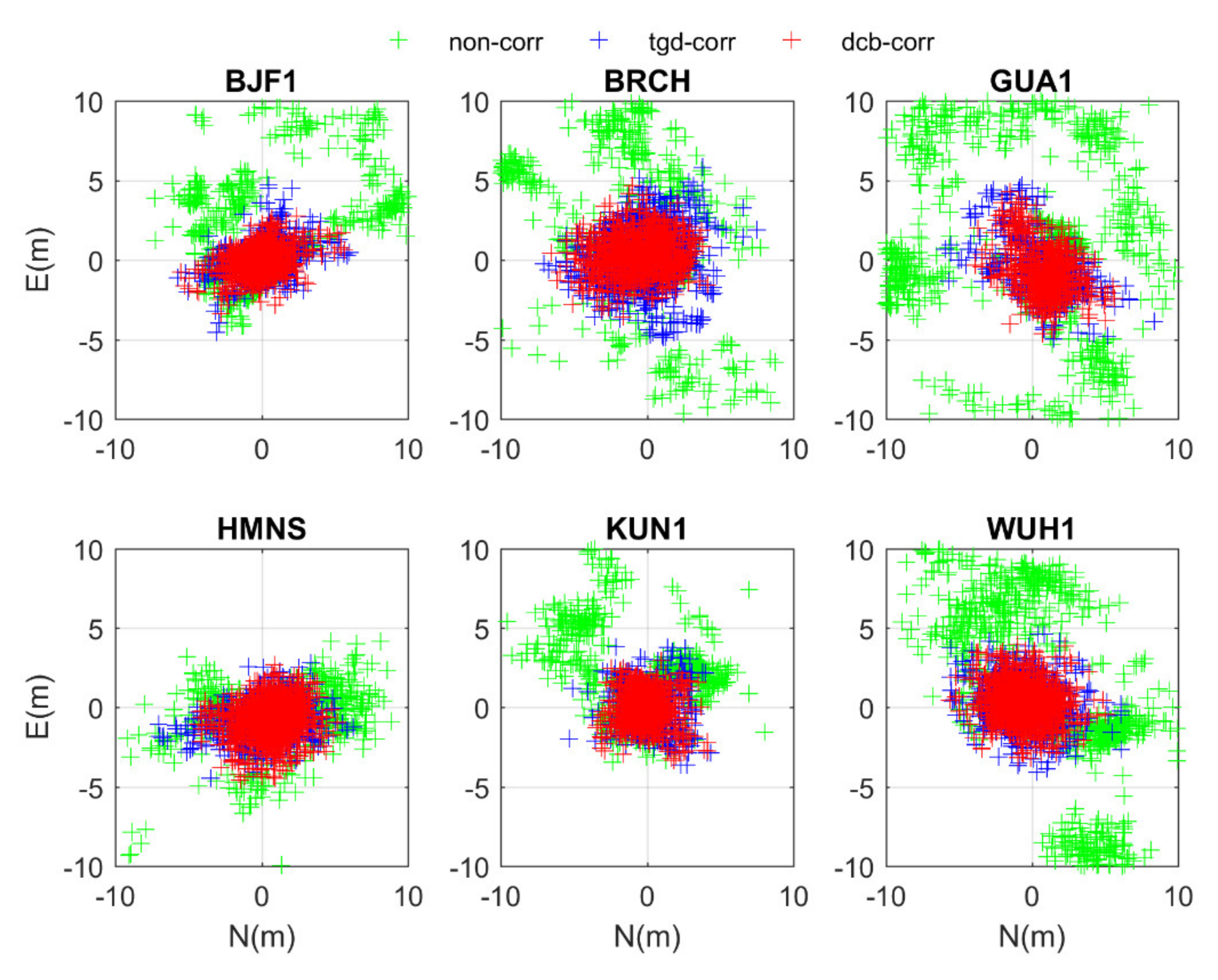
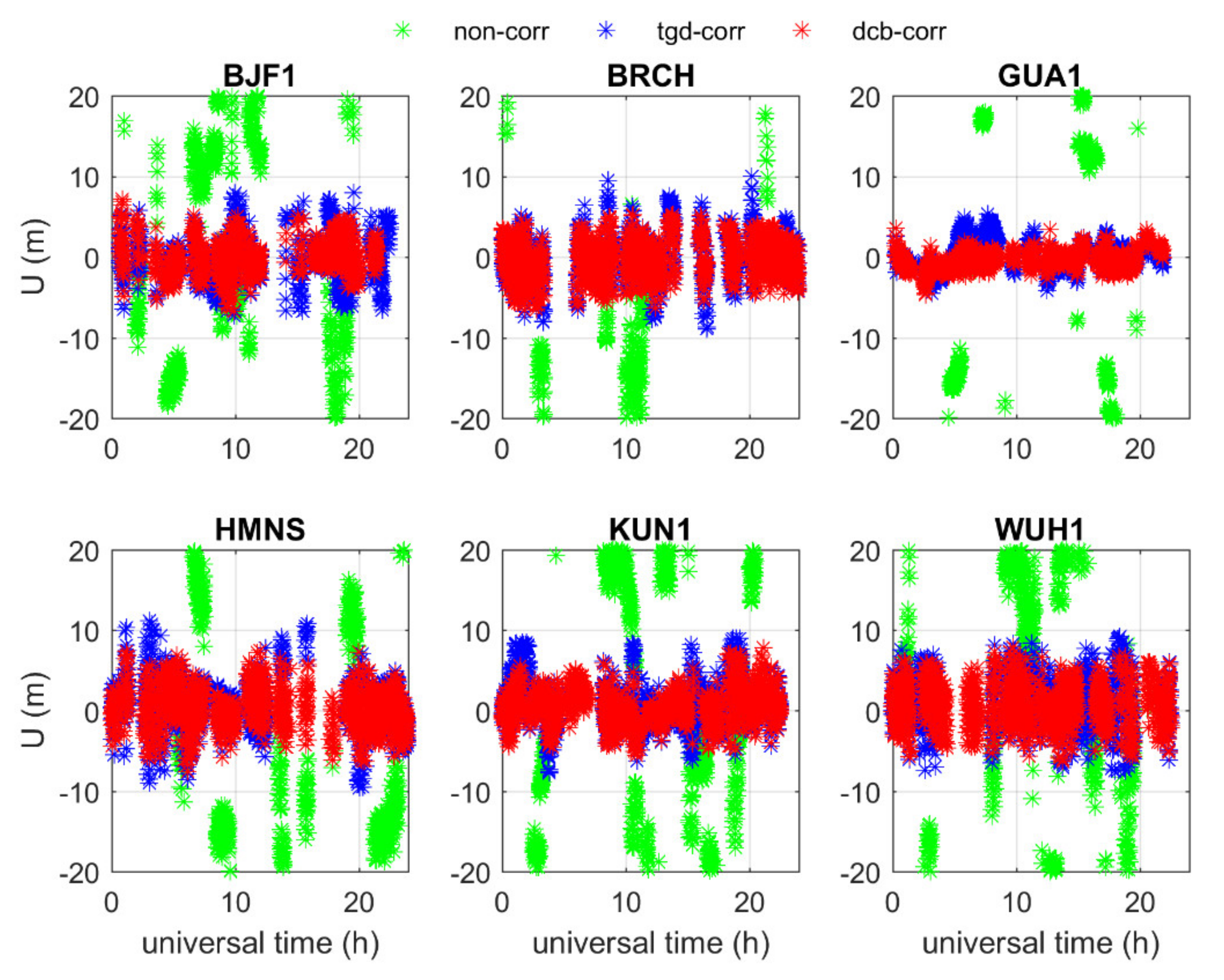
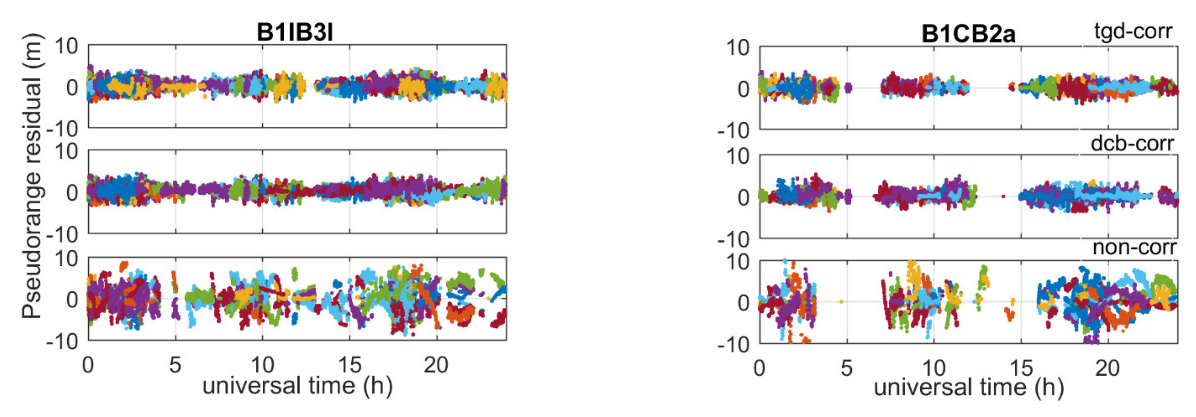
4.1. Performance of SPP
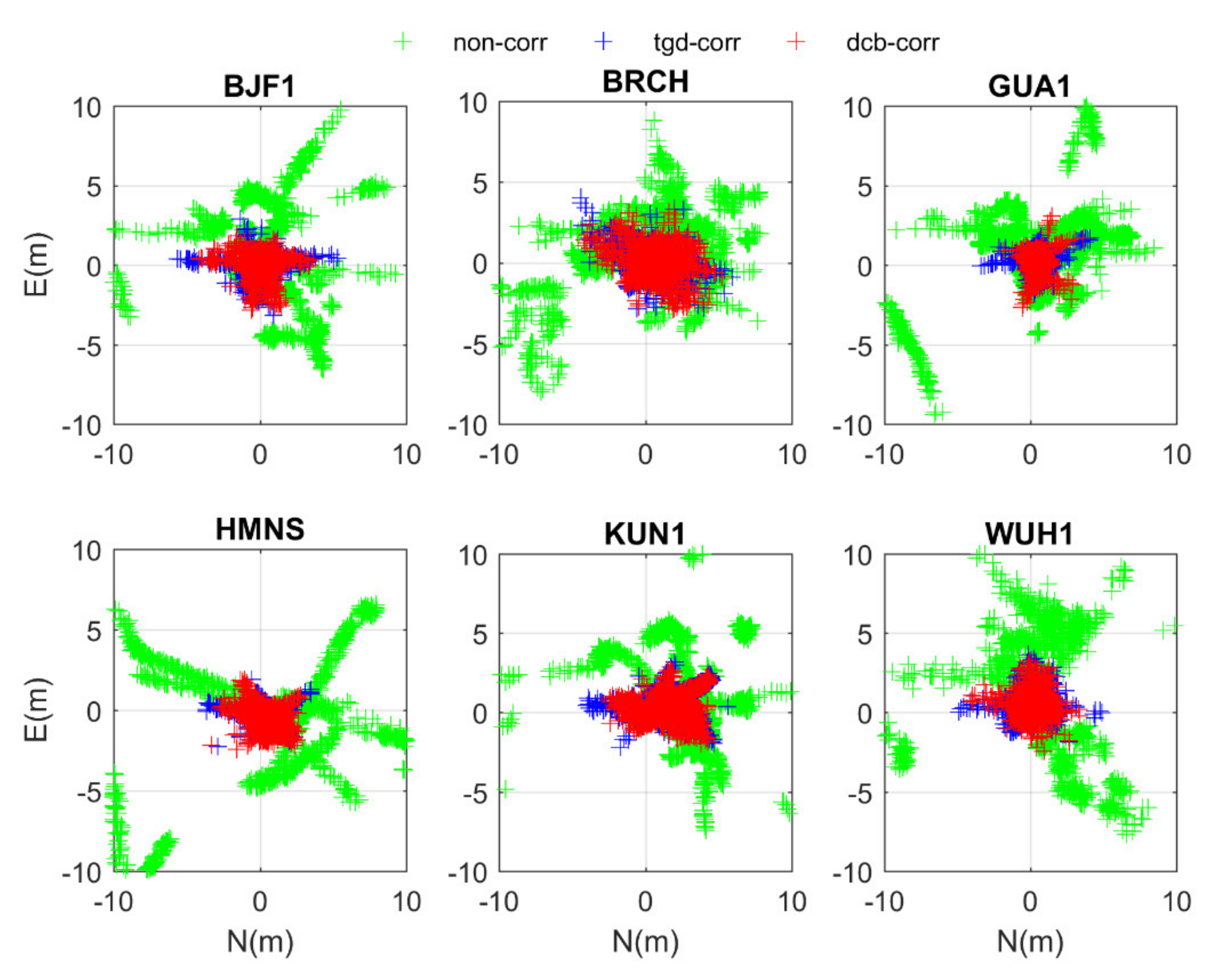
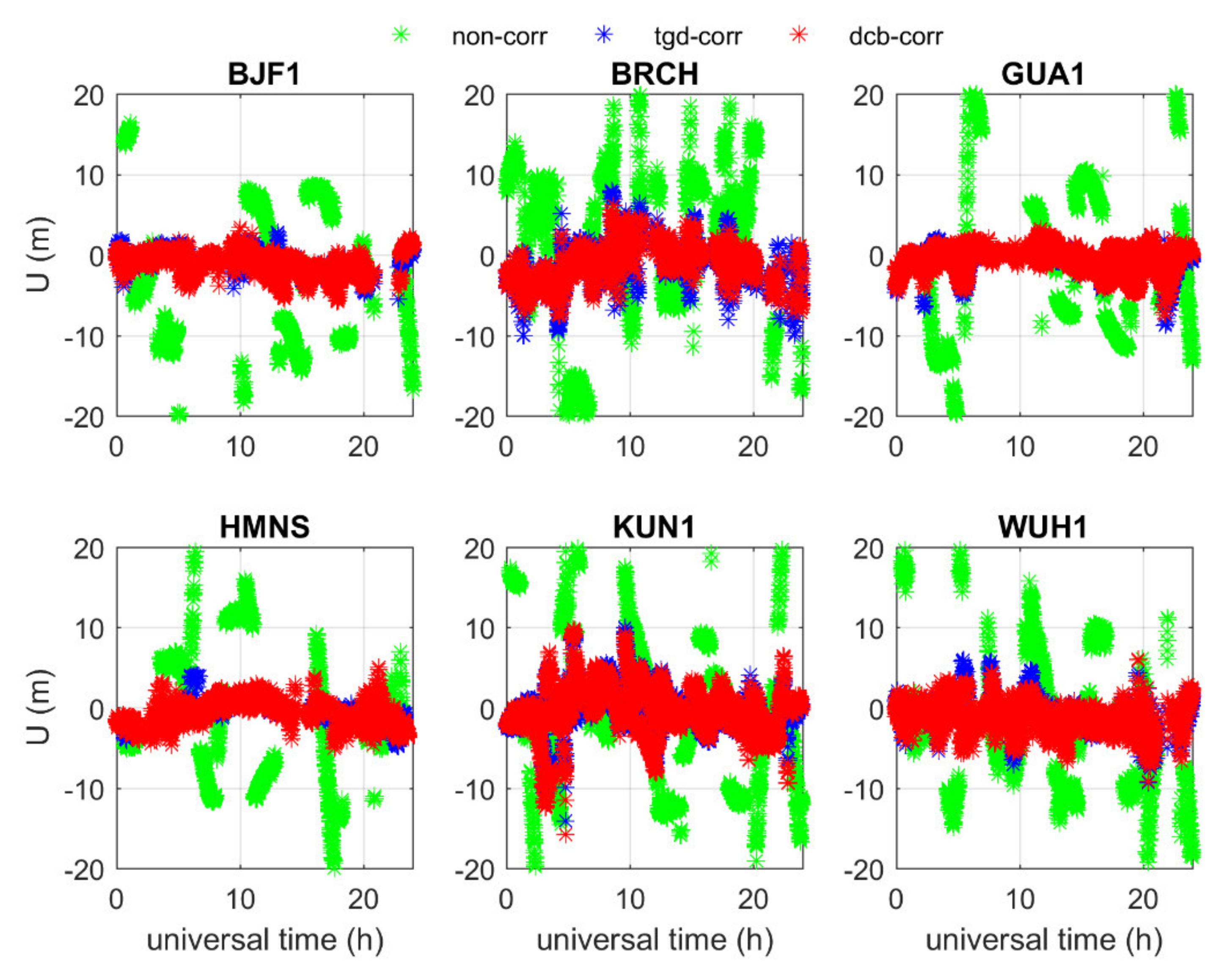
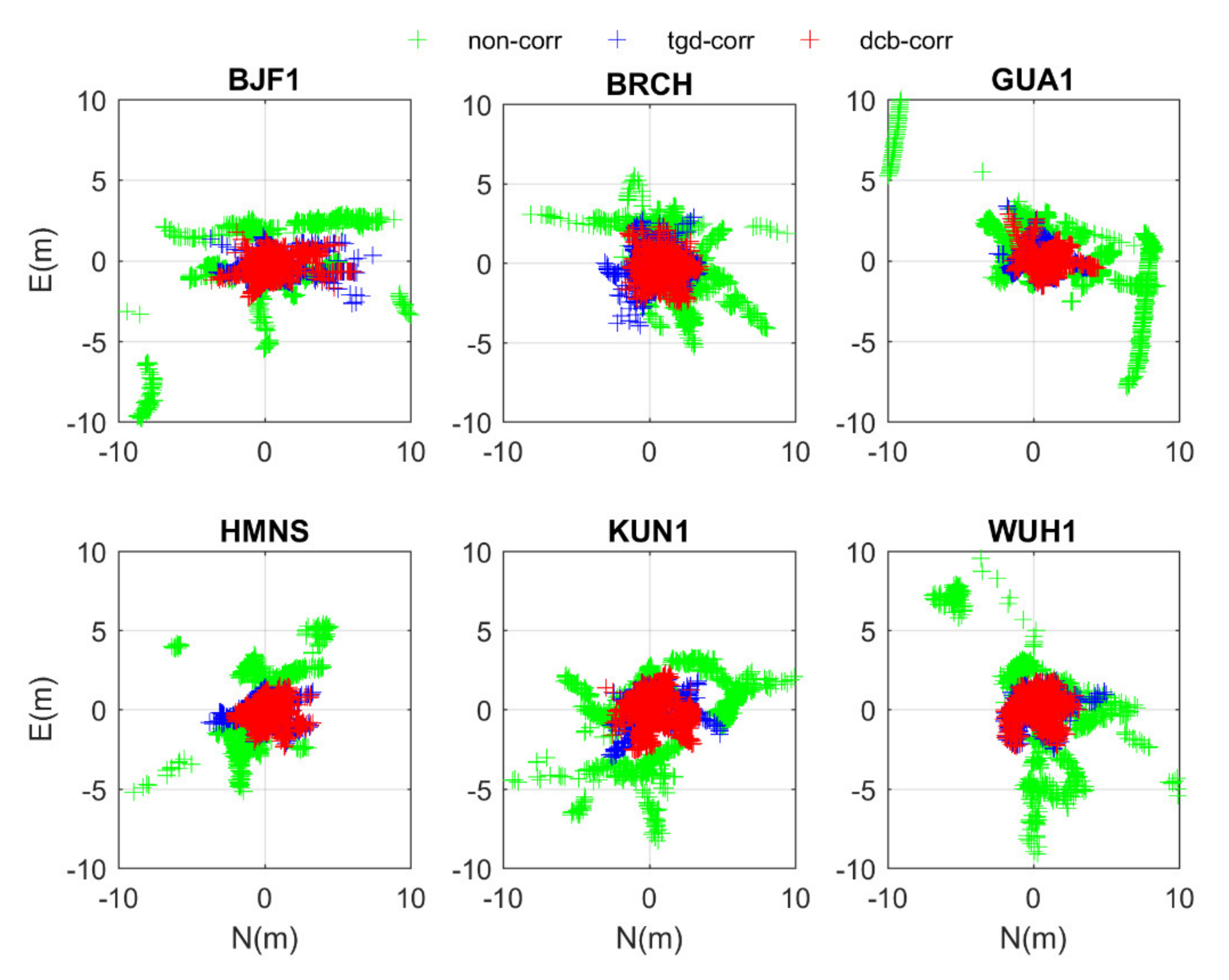
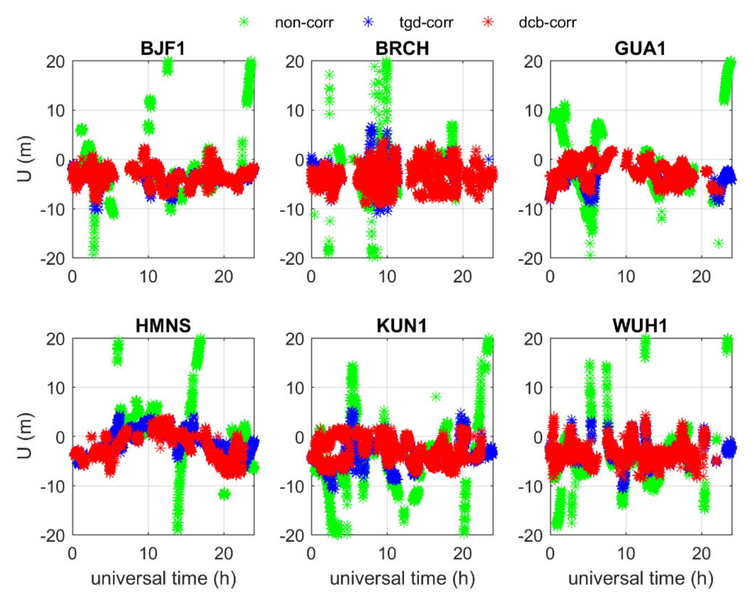
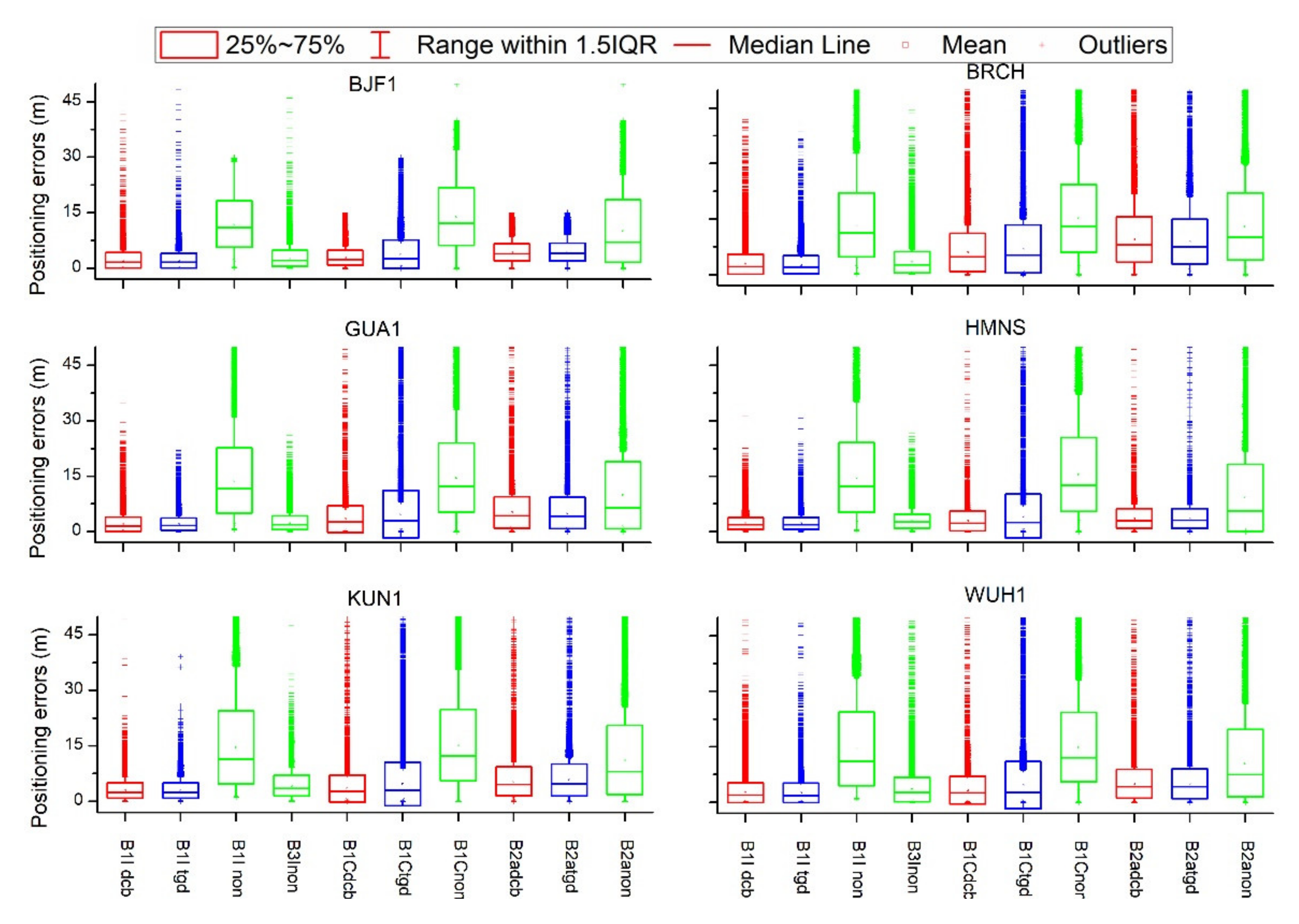
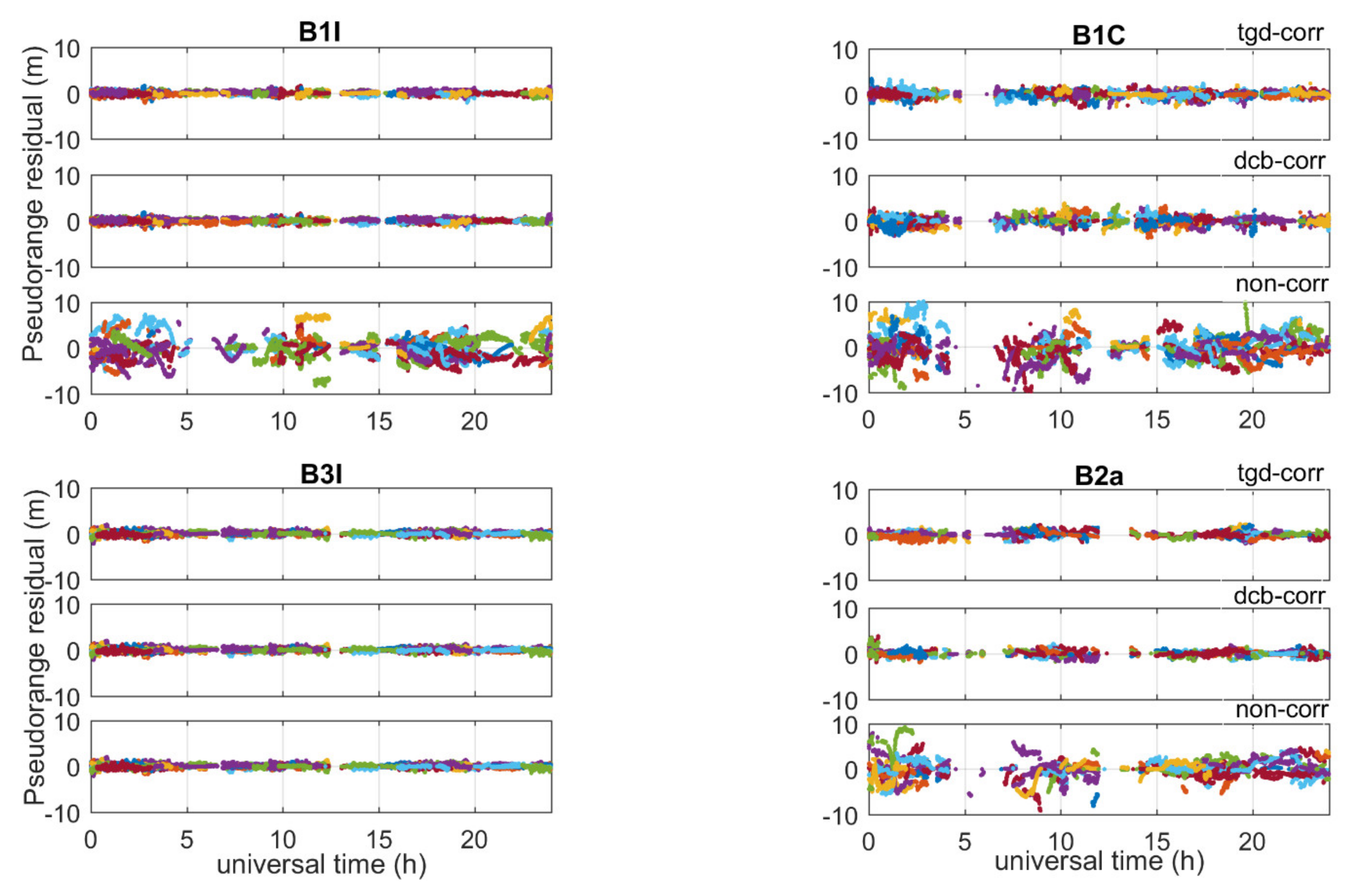
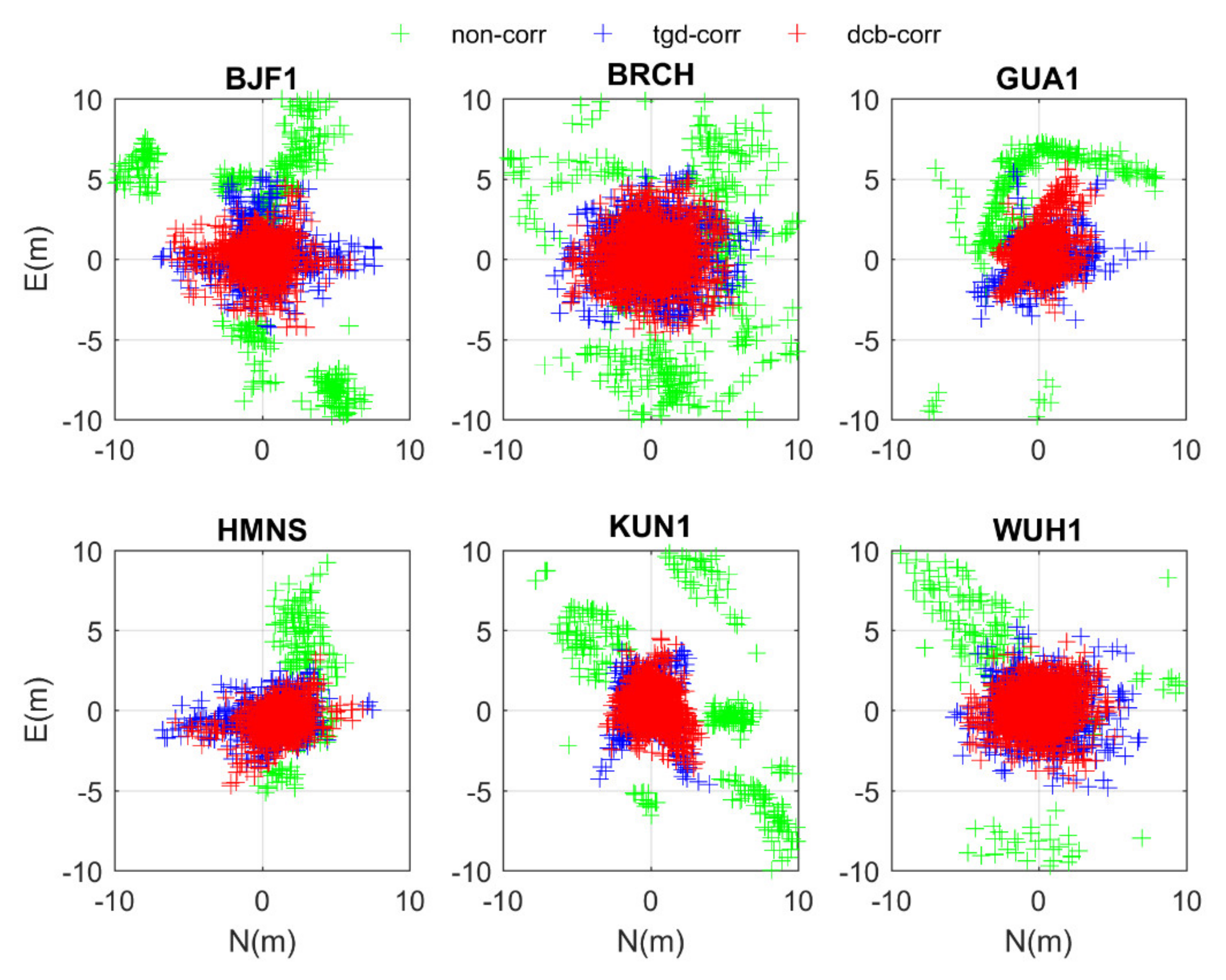
4.1.1. Single-Frequency
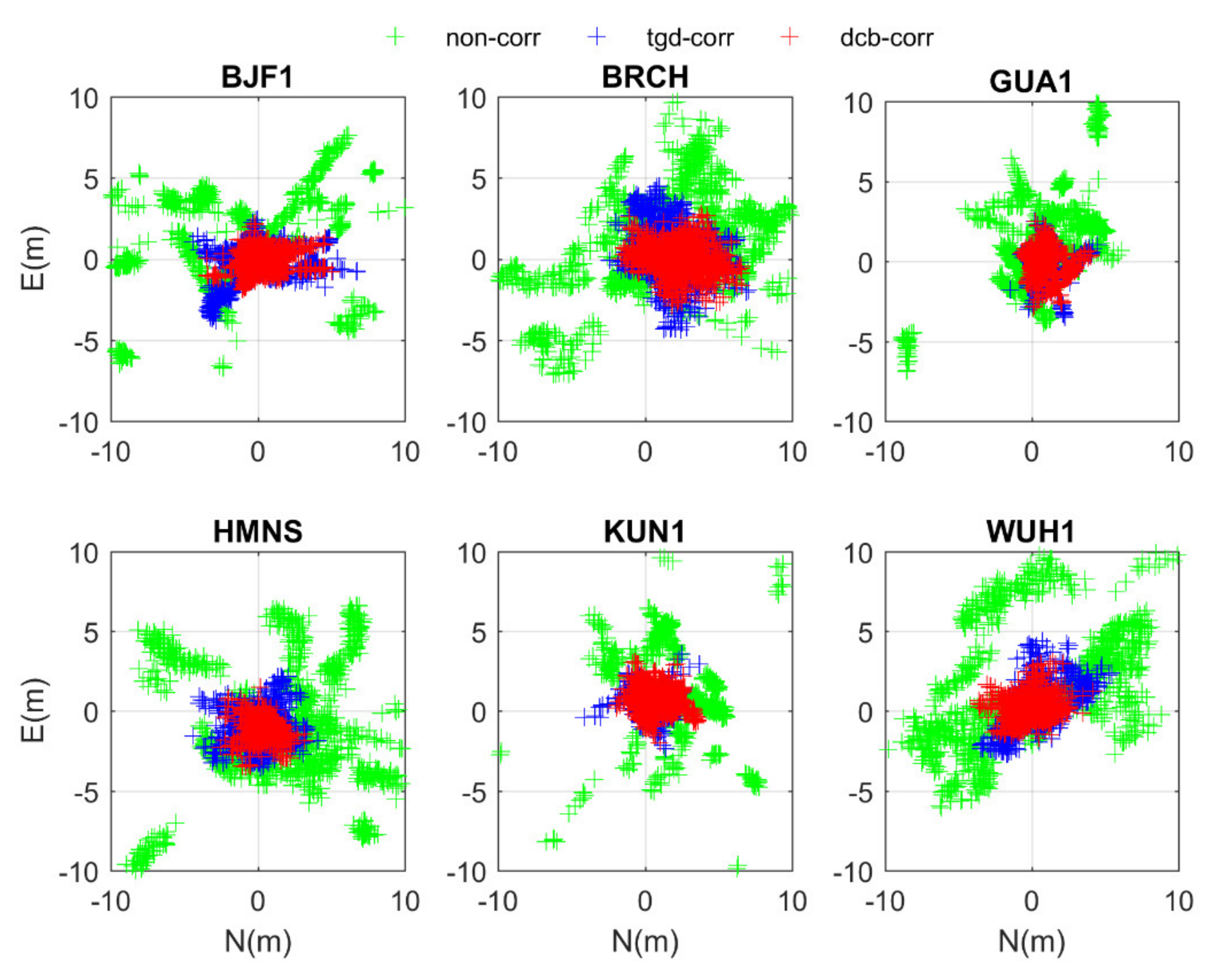
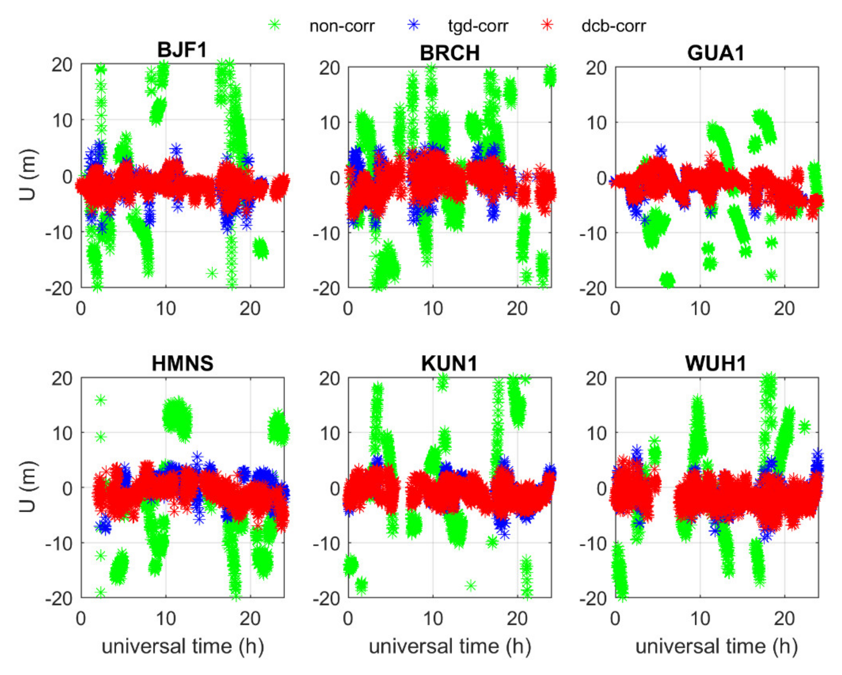
4.1.2. Dual-Frequency
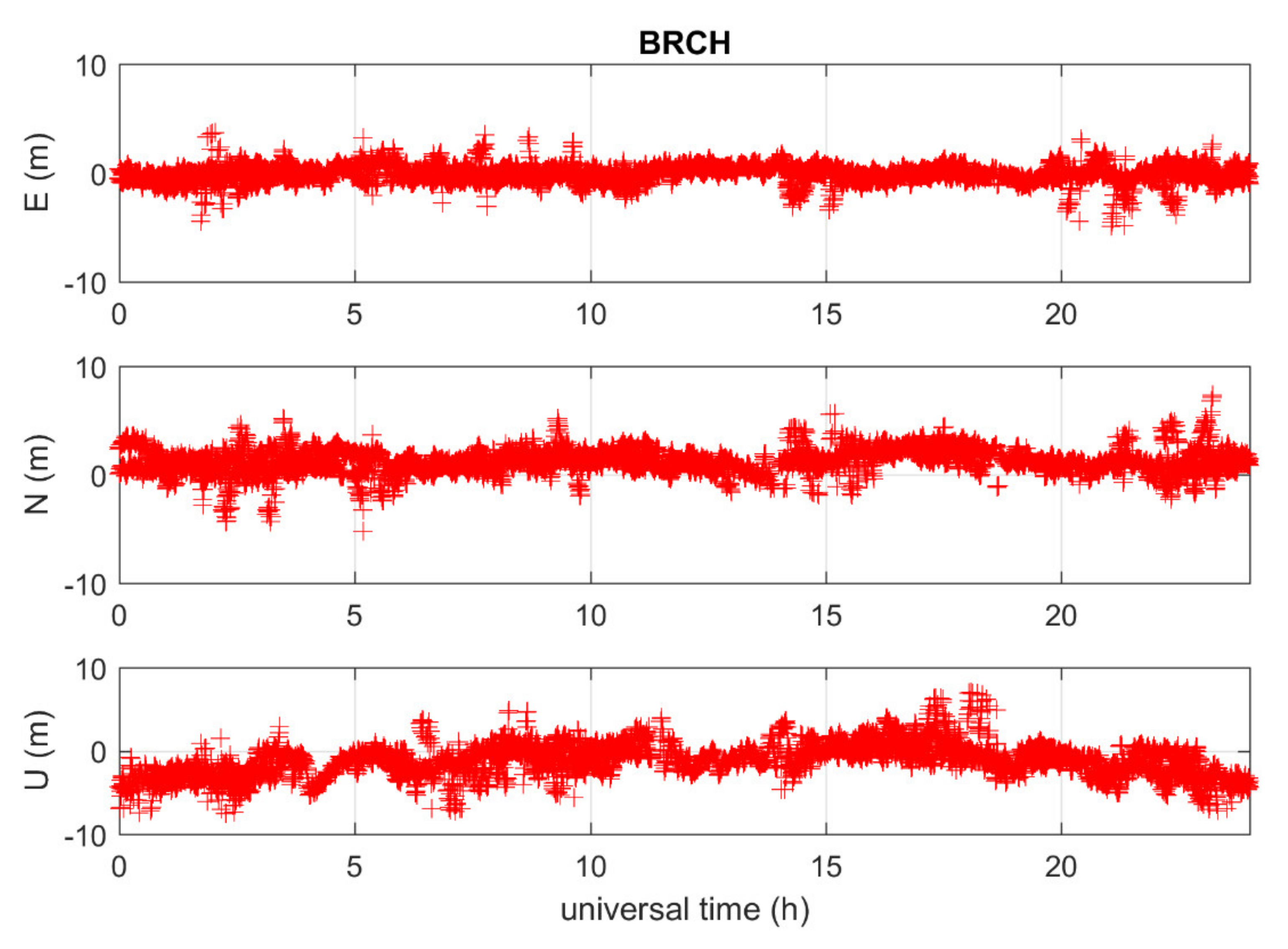
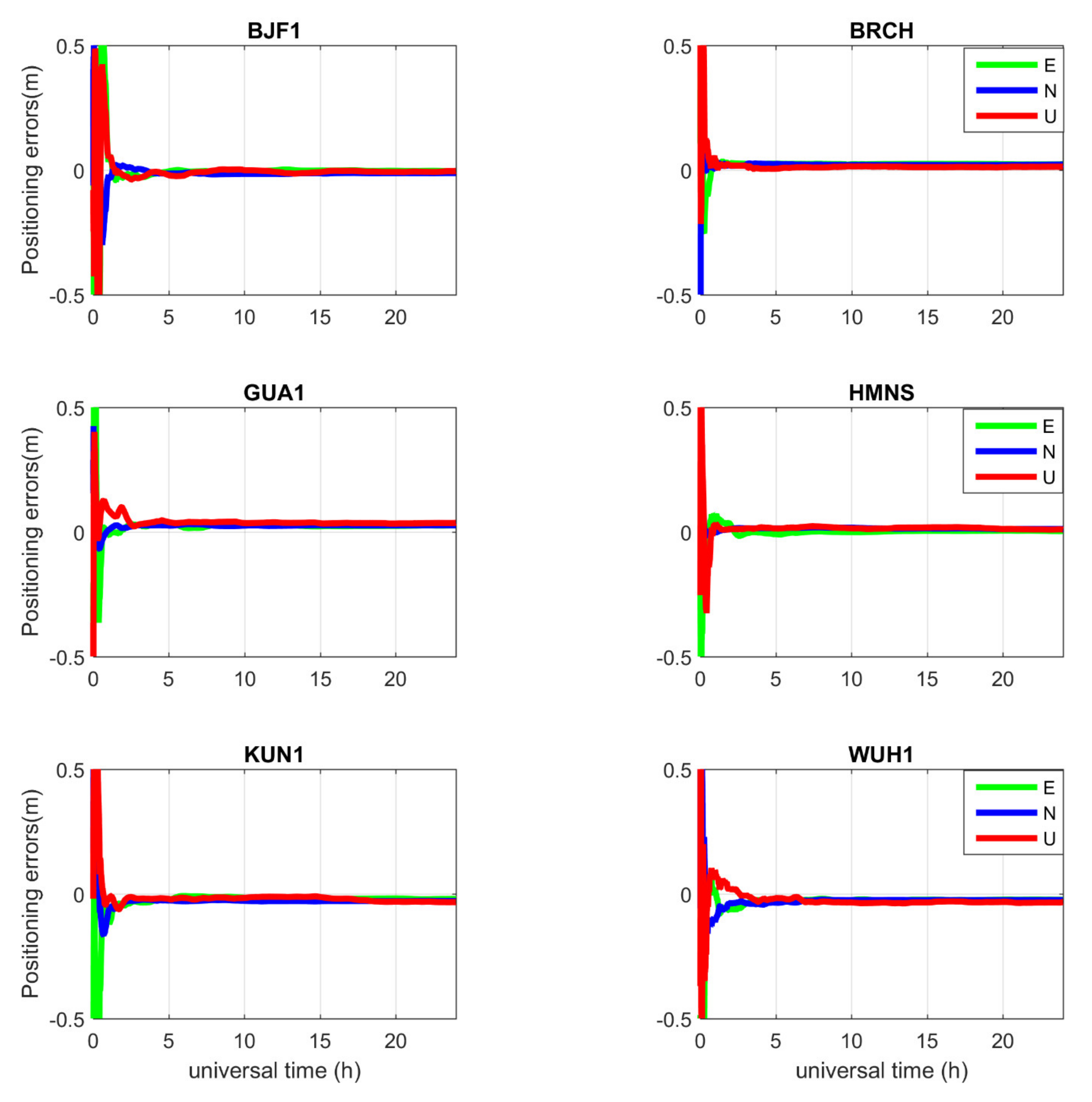
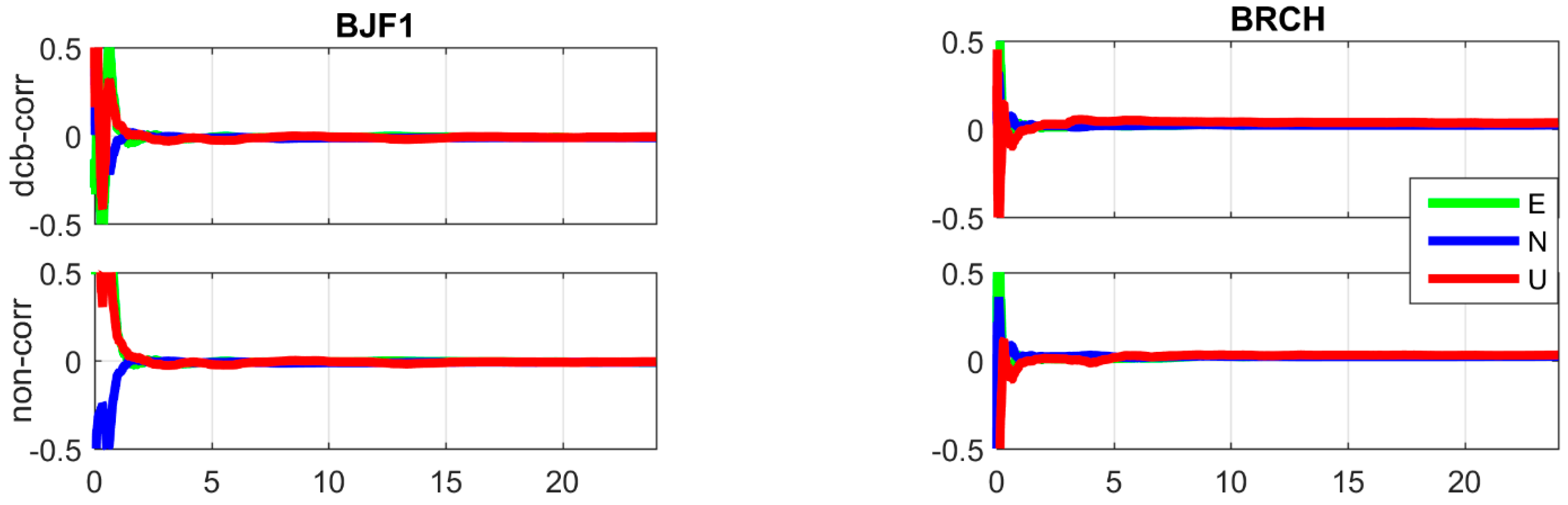
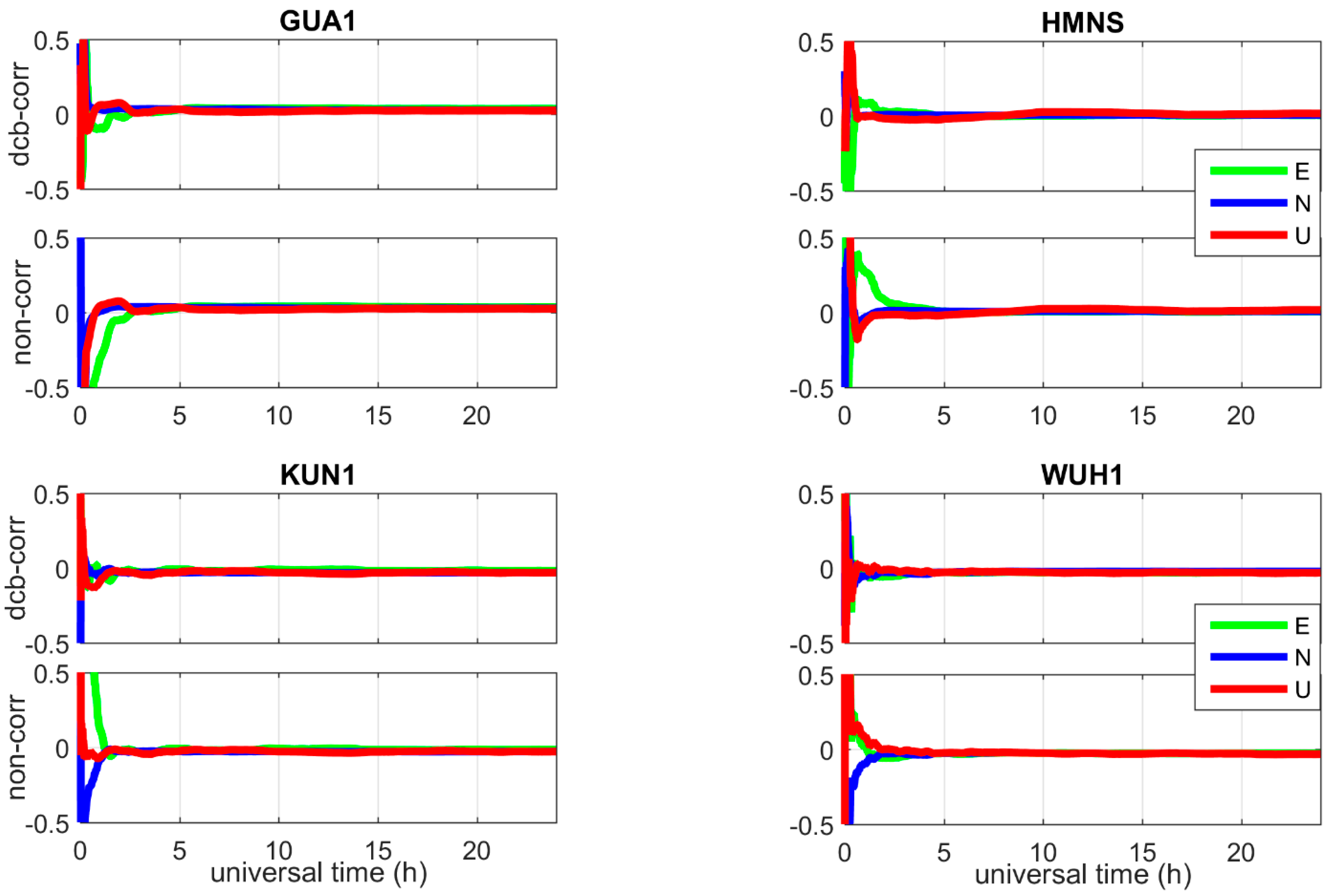
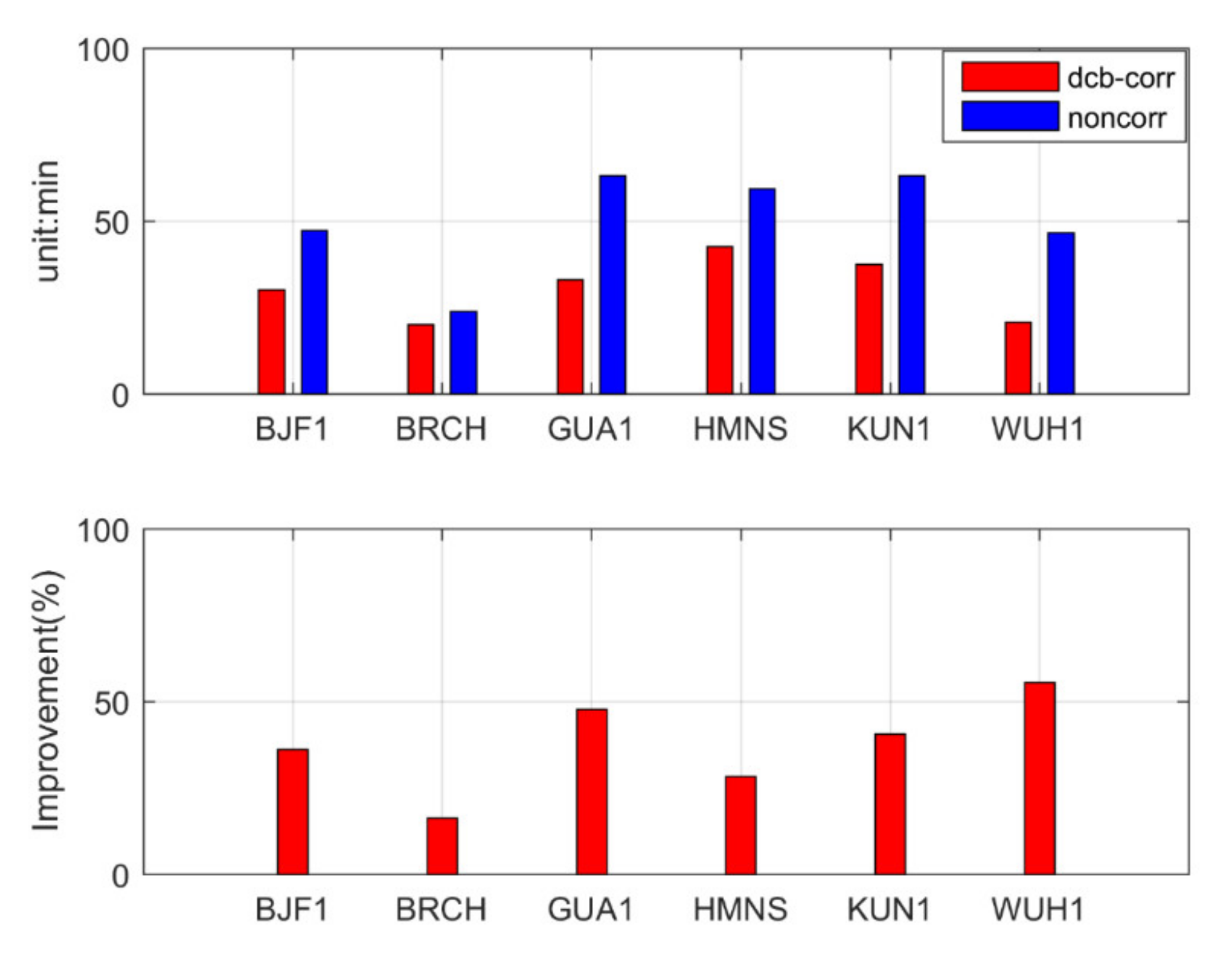
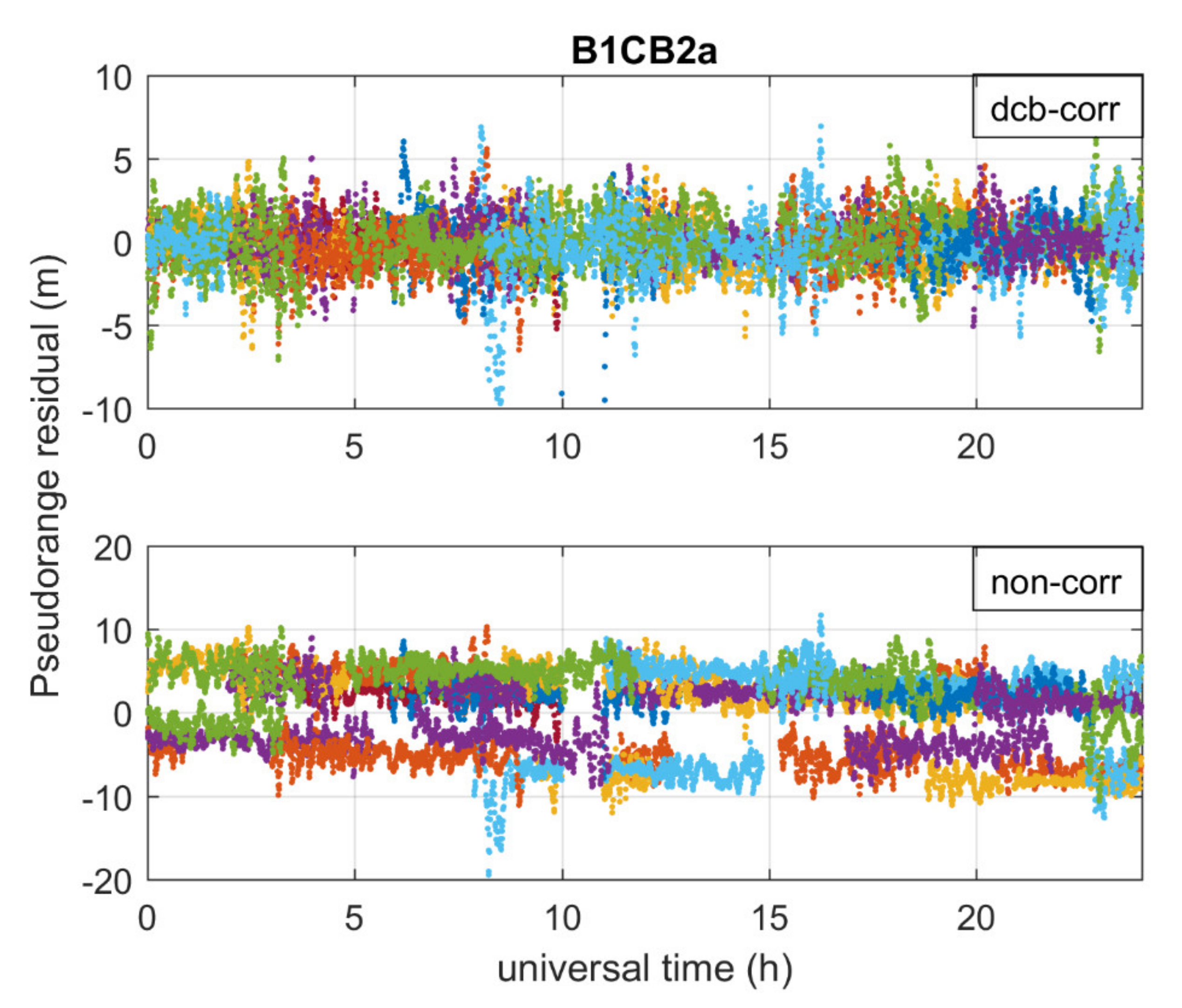
4.2. Performance of PPP
5. Conclusions
Author Contributions
Funding
Institutional Review Board Statement
Informed Consent Statement
Data Availability Statement
Acknowledgments
Conflicts of Interest
References
- Zhang, R.; Tu, R.; Liu, J.; Hong, J.; Fan, L.; Zhang, P.; Lu, X. Impact of BDS-3 experimental satellites to BDS-2: Service area, precise products, precise positioning. Adv. Space Res. 2018, 62, 829–844. [Google Scholar] [CrossRef]
- Wu, Z.; Zhou, S.; Hu, X.; Liu, L.; Shuai, T.; Xie, Y.; Tang, C.; Pan, J.; Zhu, L.; Chang, Z. Performance of the BDS3 experimental satellite passive hydrogen maser. GPS Solut. 2018, 22, 43. [Google Scholar] [CrossRef]
- Yang, Y.; Gao, W.; Guo, S.; Mao, Y.; Yang, Y. Introduction to BeiDou-3 navigation satellite system. Navigation 2019, 66, 7–18. [Google Scholar] [CrossRef]
- Xie, X.; Fang, R.; Geng, T.; Wang, G.; Zhao, Q.; Liu, J. Characterization of GNSS Signals Tracked by the iGMAS Network Considering Recent BDS-3 Satellites. Remote Sens. 2018, 10, 1736. [Google Scholar] [CrossRef]
- CSNO. BeiDou Navigation Satellite System Open Service Performance Standard, Version 2.0; China Satellite Navigation Office: Beijing, China, 2018.
- Håkansson, M.; Jensen, A.B.O.; Horemuz, M.; Hedling, G. Review of code and phase biases in multi-GNSS positioning. GPS Solut. 2016, 21, 849–860. [Google Scholar] [CrossRef]
- Montenbruck, O.; Hauschild, A.; Steigenberger, P. Differential Code Bias Estimation using Multi-GNSS Observations and Global Ionosphere Maps. Navigation 2014, 61, 191–201. [Google Scholar] [CrossRef]
- Montenbruck, O.; Hauschild, A. Code Biases in Multi-GNSS Point Positioning. In Proceedings of the 2013 International Technical Meeting of The Institute of Navigation, San Diego, CA, USA, 27–29 January 2013; pp. 616–628. [Google Scholar]
- Teunissen, P.J.G.; Montebruck, O. Springer Handbook of Global Navigation Satellite Systems; Springer International Publishing: Cham, Switzerland, 2017; pp. 967–982. [Google Scholar]
- CSNO. BeiDou Navigation Satellite System Signal in Space Interface Control Document-Open Service Signal B1I, Version 1.0; China Satellite Navigation Office: Beijing, China, 2012.
- CSNO. BeiDou Navigation Satellite System Signal in Space Interface Control Document, Open Service Signal B2a (Version 1.0); China Satellite Navigation Office: Beijing, China, 2017.
- CSNO. BeiDou Navigation Satellite System Signal in Space Interface Control Document, Open Service Signal B1C (Version 1.0); China Satellite Navigation Office: Beijing, China, 2017.
- Montenbruck, O.; Steigenberger, P.; Hauschild, A. Broadcast versus precise ephemerides: A multi-GNSS perspective. GPS Solut. 2015, 19, 321–333. [Google Scholar] [CrossRef]
- Coco, D.; Coker, C.; Dahlke, S.; Clynch, J. Variability of GPS satellite differential group delay biases. IEEE Trans. Aerosp. Electron. Syst. 1991, 27, 931–938. [Google Scholar] [CrossRef]
- Sardón, E.; Zarraoa, N. Estimation of total electron content using GPS data: How stable are the differential satellite and receiver instrumental biases? Radio Sci. 1997, 32, 1899–1910. [Google Scholar] [CrossRef]
- Liu, J.; Bi, S.; Zheng, J.; Xie, J. Effect of Separation of Navigation Satellite Antenna Inter-Frequency Phase Centers on TGD Parameter. In China Satellite Navigation Conference (CSNC) 2014 Proceedings: Volume II; Sun, J., Jiao, W., Lu, M., Eds.; Lecture Notes in Electrical Engineering; Springer: Berlin/Heidelberg, Germany, 2014; pp. 227–238. [Google Scholar] [CrossRef]
- Zhang, Y.; Chen, J.; Gong, X.; Chen, Q. The update of BDS-2 TGD and its impact on positioning. Adv. Space Res. 2020, 65, 2645–2661. [Google Scholar] [CrossRef]
- Zhang, Y.; Wang, H.; Chen, J.; Wang, A.; Meng, L.; Wang, E. Calibration and Impact of BeiDou Satellite-Dependent Timing Group Delay Bias. Remote Sens. 2020, 12, 192. [Google Scholar] [CrossRef]
- Li, X.; Xie, W.; Huang, J.; Ma, T.; Zhang, X.; Yuan, Y. Estimation and analysis of differential code biases for BDS3/BDS2 using iGMAS and MGEX observations. J. Geod. 2019, 93, 419–435. [Google Scholar] [CrossRef]
- Guo, F.; Zhang, X.; Wang, J. Timing group delay and differential code bias corrections for BeiDou positioning. J. Geod. 2015, 89, 427–445. [Google Scholar] [CrossRef]
- Ge, Y.; Zhou, F.; Sun, B.; Wang, S.; Shi, B. The Impact of Satellite Time Group Delay and Inter-Frequency Differential Code Bias Corrections on Multi-GNSS Combined Positioning. Sensors 2017, 17, 602. [Google Scholar] [CrossRef] [PubMed]
- Wang, N.; Li, Z.; Montenbruck, O.; Tang, C. Quality assessment of GPS, Galileo and BeiDou-2/3 satellite broadcast group delays. Adv. Space Res. 2019, 64, 1764–1779. [Google Scholar] [CrossRef]
- Wu, J.T.; Wu, S.C.; Hajj, G.A.; Bertiger, W.I.; Lichten, S.M. Effects of antenna orienation on GPS carrier phase. Manuscr. Geod. 1992, 18, 91–98. [Google Scholar]
- Saastamoinen, J. Atmospheric Correction for the Troposphere and Stratosphere in Radio Ranging Satellites. Use Artif. Satell. Geod. 2013, 15, 247–251. [Google Scholar] [CrossRef]
- Petit, G.; Luzum, B. IERS Conventions; No. IERS-TN-36; Bureau International Des Poids Et Mesures Sevres: Serves, France, 2010. [Google Scholar]
- Jiao, G.; Song, S.; Ge, Y.; Su, K.; Liu, Y. Assessment of BeiDou-3 and Multi-GNSS Precise Point Positioning Performance. Sensors 2019, 19, 2496. [Google Scholar] [CrossRef] [PubMed]
- Ferland, R.; Piraszewski, M. The IGS-combined station coordinates, earth rotation parameters and apparent geocenter. J. Geod. 2009, 83, 385–392. [Google Scholar] [CrossRef]
- Cai, C.; Gao, Y.; Pan, L.; Zhu, J. Precise point positioning with quad-constellations: GPS, BeiDou, GLONASS and Galileo. Adv. Space Res. 2015, 56, 133–143. [Google Scholar] [CrossRef]


| Items | Processing Strategies |
|---|---|
| Date span | 1–30 April 2020 |
| Cutoff angle | 10° |
| Ionospheric delay | Single-Frequency: BeiDou Global Ionospheric delay correction Model (BDGIM) Dual-frequency: Ionosphere-free combined observables |
| Sampling rate | 30 s |
| Phase wind-up | Corrected [23] |
| Tropospheric delay | ZHD: corrected with Saastamoinen [24] |
| ZWD: estimated [25] | |
| Tidal displacement | IERS Conventions 2010 [25] |
| Relativistic effect | Corrected [25] |
| Sagnac effect | Corrected [25] |
| PCO and PCV | Corrected using “ATX” file |
| Station reference coordinates | iGMAS SINEX solutions |
| Model | Single-Frequency | Dual-Frequency | Schemes | Comments |
|---|---|---|---|---|
| SPP | B1I, B3I, B1C, B2a | B1I/B3I, B1C/B2a | non-corr tgd-corr dcb-corr | non-corr: code without TGD or DCB corrections tgd-corr: TGD corrections dcb-corr: DCB corrections |
| PPP | - | B1I/B3I, B1C/B2a | non-corr dcb-corr |
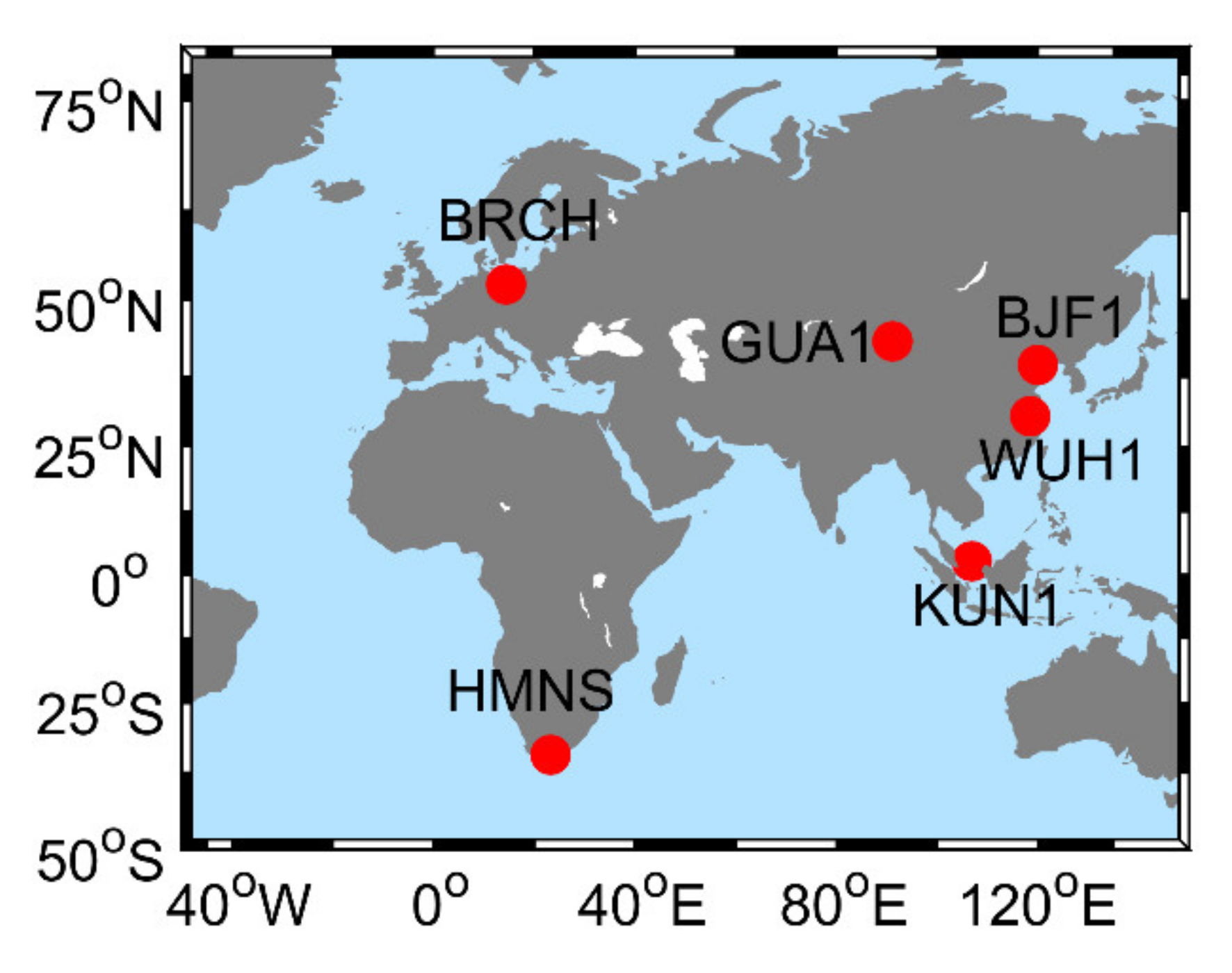
| Station | Receiver | Antenna |
|---|---|---|
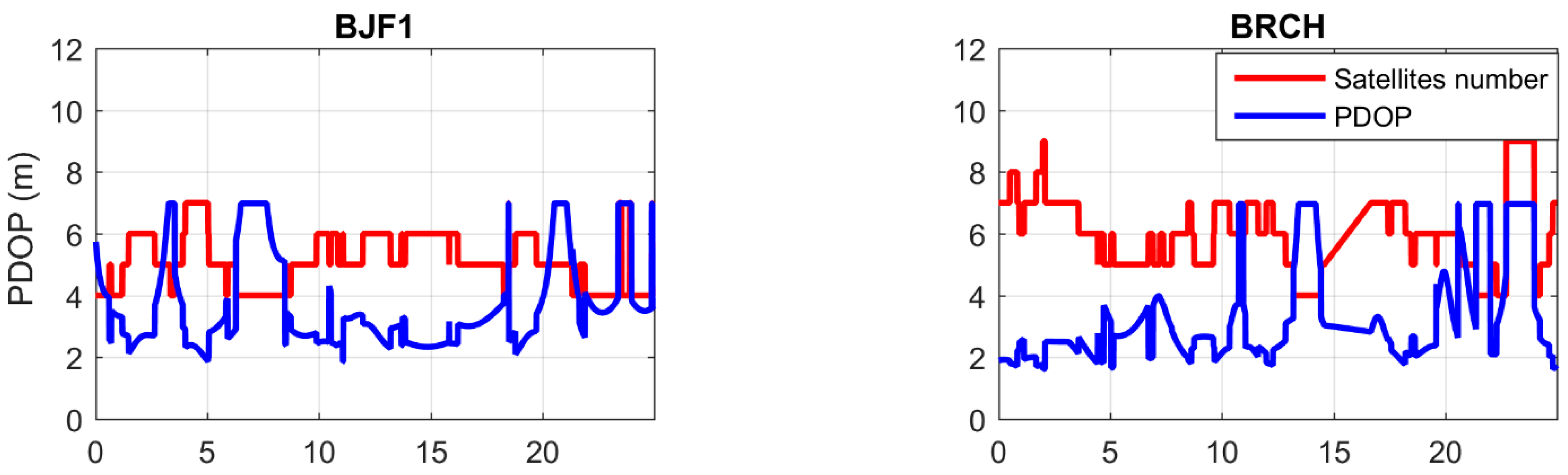
| BJF1 | CETC-54-GMR | LEIAR25.R4 |
| BRCH | CETC-54-GMR | NOV750.R4 |
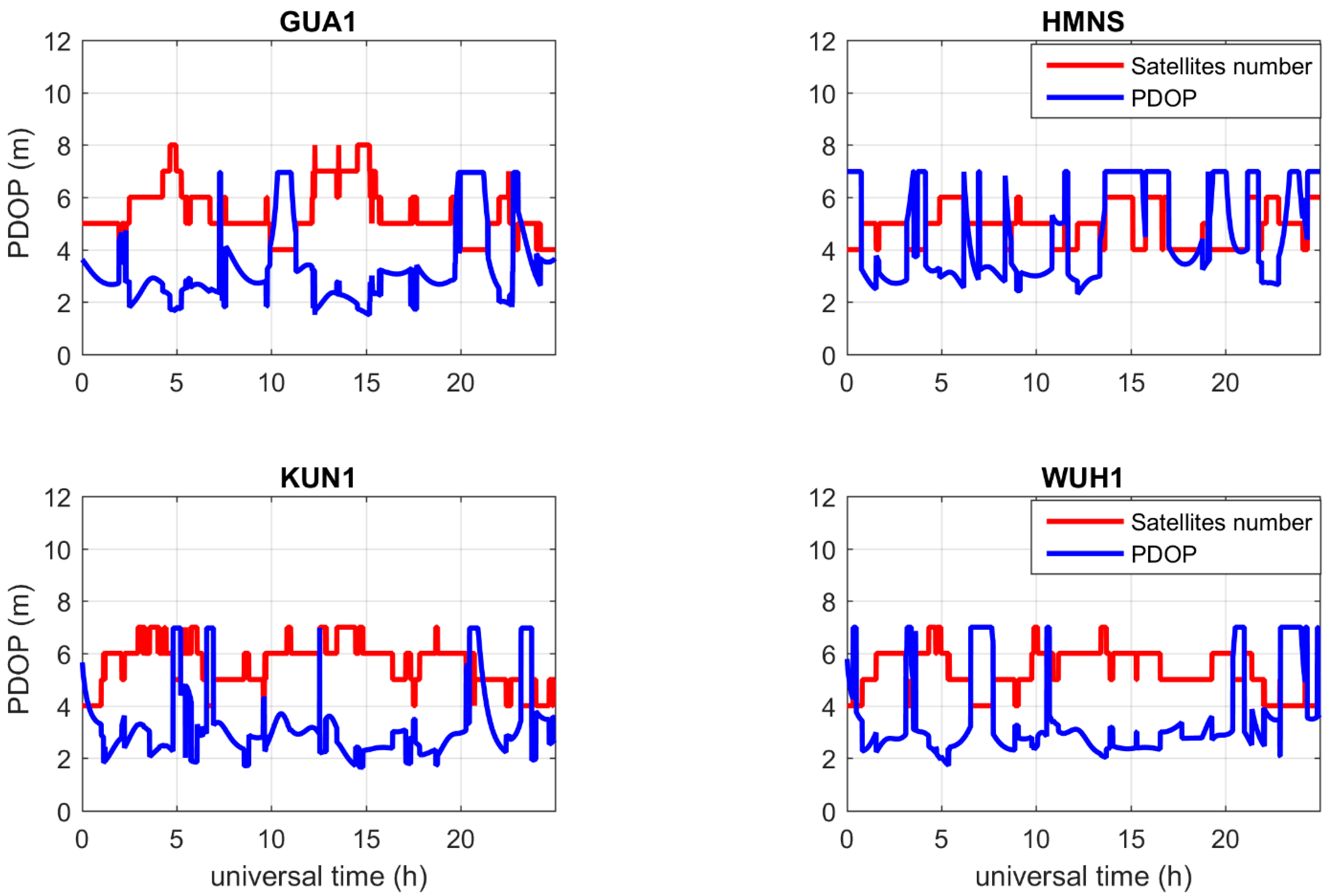
| GUA1 | GNSS-GGR | RINT-8CH |
| WUH1 | CETC-54-GMR | LEIAR25.R4c |
| HMNS | GNSS-GGR | RINT-8CH |
| KUN1 | UB4B0-13478 | NOV750.R4 |
| Scheme | B1I | B3I | B1C | B2a | ||||||||
|---|---|---|---|---|---|---|---|---|---|---|---|---|
| E | N | U | E | N | U | E | N | U | E | N | U | |
| dcb-corr | 0.85 | 1.42 | 2.26 | - | - | - | 0.98 | 1.97 | 3.53 | 1.08 | 2.93 | 3.14 |
| tgd-corr | 0.79 | 1.39 | 2.25 | - | - | - | 1.26 | 2.23 | 3.70 | 1.05 | 2.88 | 3.11 |
| non-corr | 1.52 | 2.45 | 5.92 | 0.94 | 1.74 | 2.86 | 1.66 | 2.54 | 6.08 | 1.42 | 3.85 | 5.48 |
| Improvement (%) (dcb-corr/ non-corr) | 44.1 | 42.0 | 61.8 | - | - | - | 40.9 | 22.4 | 41.9 | 23.9 | 24.0 | 42.7 |
| Improvement (%) (tgd-corr/ non-corr) | 48.2 | 43.3 | 62.0 | - | - | - | 24.1 | 12.2 | 39.1 | 26.1 | 25.2 | 43.2 |
| Scheme | B1I/B3I | B1C/B2a | ||||
|---|---|---|---|---|---|---|
| E | N | U | E | N | U | |
| dcb-corr | 1.33 | 1.75 | 2.83 | 1.35 | 1.81 | 2.91 |
| tgd-corr | 1.26 | 1.76 | 2.92 | 1.64 | 2.06 | 3.28 |
| non-corr | 3.84 | 5.83 | 6.75 | 5.28 | 5.17 | 6.17 |
| Improvement (%) (dcb-corr/non-corr) | 65.4 | 70.0 | 58.1 | 74.4 | 65.0 | 52.8 |
| Improvement (%) (tgd-corr/non-corr) | 67.2 | 69.8 | 56.7 | 68.9 | 60.2 | 46.8 |
| Scheme | B1I/B3I | B1C/B2a | ||||
|---|---|---|---|---|---|---|
| E | N | U | E | N | U | |
| dcb-corr | - | - | - | 0.021 | 0.031 | 0.031 |
| non-corr | 0.023 | 0.028 | 0.039 | 0.032 | 0.029 | 0.038 |
Publisher’s Note: MDPI stays neutral with regard to jurisdictional claims in published maps and institutional affiliations. |
© 2020 by the authors. Licensee MDPI, Basel, Switzerland. This article is an open access article distributed under the terms and conditions of the Creative Commons Attribution (CC BY) license (http://creativecommons.org/licenses/by/4.0/).
Share and Cite
Dai, P.; Xing, J.; Ge, Y.; Yang, X.; Qin, W.; Dong, Y.; Zhang, Z. The Effect of BDS-3 Time Group Delay and Differential Code Bias Corrections on Positioning. Appl. Sci. 2021, 11, 104. https://doi.org/10.3390/app11010104
Dai P, Xing J, Ge Y, Yang X, Qin W, Dong Y, Zhang Z. The Effect of BDS-3 Time Group Delay and Differential Code Bias Corrections on Positioning. Applied Sciences. 2021; 11(1):104. https://doi.org/10.3390/app11010104
Chicago/Turabian StyleDai, Peipei, Jianping Xing, Yulong Ge, Xuhai Yang, Weijin Qin, Yanchen Dong, and Zhe Zhang. 2021. "The Effect of BDS-3 Time Group Delay and Differential Code Bias Corrections on Positioning" Applied Sciences 11, no. 1: 104. https://doi.org/10.3390/app11010104
APA StyleDai, P., Xing, J., Ge, Y., Yang, X., Qin, W., Dong, Y., & Zhang, Z. (2021). The Effect of BDS-3 Time Group Delay and Differential Code Bias Corrections on Positioning. Applied Sciences, 11(1), 104. https://doi.org/10.3390/app11010104