Article

Coordinated LVRT Control for a Permanent Magnet Synchronous Generator Wind Turbine with Energy Storage System

1
Department of AI Electrical Engineering, Pai Chai University, Daejeon 15540, Korea
2
Automation & Control Section, Department of Electronic Systems, Aalborg University, 9220 Aalborg East, Denmark
3
School of Electrical Engineering, Shandong University, Jinan 250061, China
4
School of Energy Systems Engineering, Chung Ang University, Seoul 06974, Korea
*
Author to whom correspondence should be addressed.
Appl. Sci. 2020, 10(9), 3085; https://doi.org/10.3390/app10093085
Submission received: 25 March 2020 / Revised: 19 April 2020 / Accepted: 22 April 2020 / Published: 28 April 2020
(This article belongs to the Section Electrical, Electronics and Communications Engineering)

Abstract

:
This study introduces a coordinated low-voltage ride through (LVRT) control method for permanent magnet synchronous generator (PMSG) wind turbines (WT) interconnected with an energy storage system (ESS). In the proposed method, both the WT pitch and power converters are controlled to enhance the LVRT response. Moreover, the ESS helps in regulating the dc link voltage during a grid fault. Previous LVRT methods can be categorized into strategies with or without an additional device for the LVRT. The latter scheme is advantageous from the perspective of no additional installation cost; in this case, pitch and converter controllers are used. Meanwhile, the former method uses an additional device for LVRT operation and hence, involves additional expense. However, it can effectively enhance the LVRT response by reducing the LVRT burden on the WT. Moreover, the additional device can be used for various WT power control applications and it is common that the ESS is interconnected to the WT for multiple objectives. Previous studies focused on these two aspects separately; hence, a method of coordinated control for an ESS and a WT is needed as more ESSs are required to connect to WTs for flexible wind power operation. The proposed method introduces a control method with different LVRT modes considering the ESS state of charge (SoC). When the WT does not have a sufficient inertial response operation range, the ESS reserve energy capacity is required for LVRT operation. This coordinated LVRT method employs both the WT and ESS controls when it is hard to handle the LVRT using the WT control alone at high wind speeds. In this case, power curve analysis is used to obtain the appropriate power reference during the fault period. In addition, a power reference is also used to ensure a safe operation. Using the proposed method, an ESS can be operated in a manner that is appropriate for WT operation, especially at high wind speeds. To validate the effectiveness of the proposed method, we considered two case studies. One study compares the LVRT response between the WT itself and the proposed method. The other research work compares the response of the conventional LVRT method that uses a WT and an ESS and with that of the proposed method. From these case studies, we concluded that the proposed method achieved a better performance while operating within the constraints of the WT rotor speed and ESS SoC limits.

1. Introduction

WPS are the fastest growing renewable energy sources from the perspective of cost and that of benefits. There are many benefits to using a permanent magnet synchronous generator (PMSG) as opposed to the DFIG; PMSGs and DFIGs are the two most popular systems used in WPS operation. A PMSG has several advantageous features, such as the absence of a gearbox, high power density, and a simple control mechanism with high precision; however, its cost is greater than that of a DFIG because it uses permanent magnets and needs topologically full power converters [1,2]. As many power electronics-based converters require intricate control mechanism driven by complex strategies, this full power converter is beneficial in terms of WP control [3,4]. Initially, a WPS is required only to operate at the maximum power point tracking (MPPT) to produce as much power as possible at a given wind speed using model-based or model-free methods [5]. Even though the WP experiences fluctuations and uncertainties in its power production, they had no significant impact on grid stability because their proportions were relatively low when compared to the total power produced by the grid. However, when many WPSs are integrated into a power network, these fluctuations and uncertainties can result in a significant impact on the operation of the grid [6,7]. Therefore, grid operators require WPSs to support stable grid operation by setting up a grid code. One of the major issues in developing a grid code for WP is the low-voltage ride through (LVRT). Using an LVRT grid code for WPSs, a grid can recover from a low voltage grid fault and achieve stable operation immediately after the occurrence of the fault [8]. Recently, the universal grid code was introduced in Reference [9] after taking into consideration the entire set of LVRT requirements of all countries. We considered the most extreme requirement from this set to validate the effectiveness of the proposed method.
Grid code requirements vary depending on the power system. Each grid code defines the specific duration for which a wind turbine (WT) should remain connected during the fault period; this duration depends on the voltage sag level [8]. Thus, the grid code is related to power system characteristics and should be varied according to the WP penetration level. As shown in Figure 1, different countries have different requirements regarding the LVRT connection time; this parameter also takes into consideration the zero voltage condition.
Various methods have been proposed in the past for LVRT control. These methods can be categorized into two groups. One group is characterized by the WT alone handling the LVRT while the other group uses additional devices such as FACT, energy storage system (ESS), or other energy dissipating devices [10]. A PI current controller for dc link voltage regulation using current feed-forward methods was proposed for better transient response; further, the impact of unbalanced voltage sags on the controller performance was studied [11]. A feedback linearization controller was proposed in Reference [12] for nonlinear control of the GSC in a PMSG. Using this controller, the performance of the GSC current control strategy during a voltage sag was improved by maintaining its rate of current flow within a given range. Because this method is quite complex to implement, feedback linearization was implemented using a sliding mode control [13].
A sliding mode control algorithm was applied in the GSC control scheme to regulate the dc link voltage [14]. This results in a better performance compared to that obtained using a linear control strategy as dc link voltage dynamics are nonlinear and the GSC exhibits this nonlinearity in its switching operation. [15] proposed a combined control for pitch and RSC control. The authors also used a breaking resistor to ensure that the WPS did not reach the current limit or rotor speed limit during LVRT. In some previous studies [16,17], an RSC was used instead of a GSC to handle dc link regulation during grid faults, as the latter had to control its active as well as reactive power support during a grid fault. Thus, it may be more beneficial to exchange the roles of the GSC and RSC with respect to DC link regulation. In this case, rotor speed can be increased by storing the remaining mechanical power as WT inertia similar to that observed during grid fault. In Reference [17], a feedback linearization strategy for RSC control was designed. In Reference [18], a nonlinear robust controller was designed to mitigate the dc link voltage fluctuation after taking the nonlinear behavior of the dc link voltage into consideration.
For LVRT operation, some authors considered the methods using additional device installations. In recent years, ESSs are being connected to WPSs for achieving many objectives by modulating the WP [6]. This can aid in the integration of WP into the grid and also makes the WPS more cost efficient. According to one strategy, an ESS can assist a WT as an LVRT solution [19]. This methodology resulted in a better LVRT response when compared to the response obtained using only the WT converter control; in addition, an ESS stores power instead of simply dissipating it. In Reference [20], the authors proposed an energy storage-based LVRT method with a direct-drive WPS having no power control capability. In References [21,22], LVRT methods were proposed using an ESS to enhance the LVRT response; in these cases, an ESS was interconnected with wind farms to help voltage restoration at the PCC. For better reactive power support during grid faults, the optimal reactive power control method was proposed to minimize production cost in Reference [23]. Even though many LVRT control methods utilizing an ESS have been introduced, the coordinated control method for the LVRT method using an ESS has not been sufficiently studied. This coordinated LVRT method is important both for economic and reliable operation. However, to the best of the authors’ knowledge, there are no methods to share the burden of LVRT power reduction between the WT and the ESS after considering operation constraints.
In this study, we propose a coordinated LVRT control method using pitch, PMSG WT converters, and an ESS. Several previous studies on LVRT methods focus on improving its transient response. We focused on coordinating the WPS (pitch and inertia modulated) and ESS controls and on recognizing when the WT cannot handle the LVRT operation by itself. Before applying the coordinated control, we evaluate if the ESS LVRT response is required by analyzing WP equation. In the case of high wind speeds, an ESS LVRT response is required in addition to the WPS LVRT response, after taking into consideration the rotor speed and converter current limits. If an ESS LVRT response is not required, the WPS LVRT response alone can be used. When an ESS LVRT response is needed, the power reference considering the pitch dynamics and rotor speed limit is used for the LVRT. By using the proposed method, the capacity required for the ESS to support the LVRT could be evaluated. Therefore, the energy required for the ESS could be conserved according to the current operational status of the WPS, resulting in a cost-effective ESS state of charge (SoC) management. From the simulation results, we validated that the proposed method can effectively achieve the LVRT at high wind speeds that can result in significant rotor speed violations during WT LVRT control. We consider two case studies. One case study compares the LVRT response of the WT itself and that of the proposed method. The other study compares the response of the conventional LVRT method that uses the WT and the ESS with that of the proposed method. From these case studies, it can be concluded that the proposed method achieves the best performance in operating within the constraints of the WT rotor speed and ESS SoC limits. This is very important for coordinated LVRT control, because the LVRT operation can result in significant damages to the WT and ESS when the rotor speed and the ESS violate their operational limits. Compared to the previous methods the benefits of the proposed method can be described as follows.
  • The proposed method can effectively control both of a WT and an ESS without violation of operational constraints.
  • From the proposed method, the stability of the LVRT operation can be improved in any wind speed conditions and it can prevent failures in both a WT and an ESS.
  • The proposed method can be applied with previous coordinated control methods by improving its stability.
  • No additional device such as chopper is required for achieving stable operation by dissipating power during grid faults.

2. PMSG Wind Power Systems

In this section, we illustrate the mechanical power of the WT, RSC, and GSC models and dc link voltage dynamics.

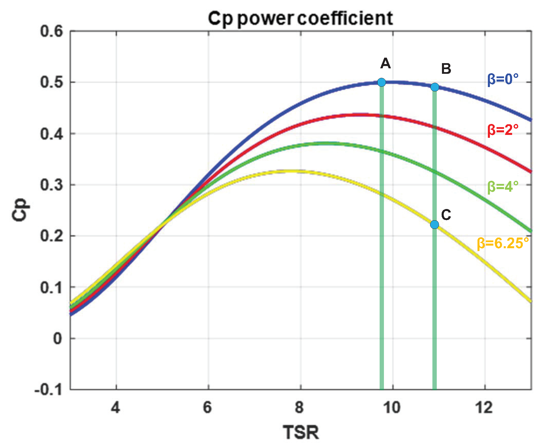
2.1. Mechanical Power of Wind Turbine

The mechanical power of a WT can be described by defining the power coefficient, C p which is modulated by the rotor speed and pitch angle, β , and controllers. By controlling the rotor speed and pitch angle, the tip speed ratio, λ , can be modulated and when the tip speed ratio maintains its optimal value, the maximum available mechanical power of the WT can be achieved [15].
P t = 1 2 ρ A C p ( λ , β ) v w i n d 3 , λ = ω m R v w i n d ,
where ρ denotes the air density, and A is the blade-swept area, which increases as the rotor radius, R, increases. C p is a function of the pitch angle and the tip speed ratio and the parameters of this function are obtained from WT experimental data. v w i n d is the wind velocity whose cubic value and tip speed ratio affect the mechanical power. Therefore, the power coefficient indicates the ratio of electricity produced by the WT to the total power available from the wind speed. Its theoretical limit is defined mathematically as 0.5926 , and the achievable value is less than this limit owing to the loss experienced by the mechanical systems in a WT. We use a maximum C p value of 0.5 in this study, which is less than the mathematical limit.

2.2. Rotor Side Converter Model

To describe RSC power production, PMSG electrical equations reflecting voltage and current are used; its electrical and mechanical torque can be calculated from the equations given below [16].
v d g = R s i d g + L s d i d g d t ω s L s i q g , v q g = R s i q g + L s d i q g d t + ω s L s i q g + ω s λ f , T e = 3 2 p λ f i q g , T m T e = J d ω m d t ,
where v d g and v q g denote the stator voltages of the PMSG while i d g and i q g indicate stator currents. L s and R s denote the stator inductance and resistance, respectively, and ω s denotes the rotor flux electrical speed. ω m denotes the speed of the PMSG mechanical rotor, λ f indicates the rotor flux, and p, which represents the ratio of electrical speed to mechanical speed, indicates the machine pole pairs. T e denotes the electromagnetic torque and T m indicates the mechanical torque. J represents rotor inertia. Therefore, rotor speed can be calculated using equations that describe the relationship between T e , T m , and J. Hence, a surface-mounted PMSG with similar d- and q-axis inductances was used in this investigation. Thus, a reluctance torque that is induced by the difference between these inductances does not exist. Therefore, we can use the Equation (2) to calculate the electromagnetic torque.

2.3. Grid Side Converter Model

The GSC dynamic model in a direct quadrature (DQ) rotating reference frame can be described as follows [24].
v d = v i d R i d L d i d d t + ω L i q , v q = v i q R i q L d i q d t + ω L i d ,
where, L and R denote grid inductance and resistance, respectively. v d and v q indicate the grid voltages in the DQ frame. i d and i q denote the grid currents in the DQ frame. v i d and v i q denote the GSC voltages in the DQ frame. Before we use the DQ rotating reference frame, we assume that the d-axis of the rotating reference frame is aligned with the grid voltage. Thus, the active and reactive powers from the GSC to the grid can be written in the form of the following equations [24].
P g r i d = 3 2 v d i d , Q g r i d = 3 2 v d i q ,
where, P g r i d and Q g r i d are the active and reactive powers, respectively. From the above assumption, GSC active and reactive powers can be modulated independently using i d and i q .

2.4. DC Link Voltage Model

A dc link is an energy buffer between the RSC and GSC. Its voltage can be described by the difference in power production between the RSC and GSC using the following equation [17].
P c = C V d c d V d c d t = P g P g r i d ,
where P g and P g r i d denote RSC and GSC power, respectively. P c describes the power stored in the dc link. V d c denotes the dc link voltage and C indicates the dc link capacitor. As described by Equation (5), the dc link voltage model is nonlinear.

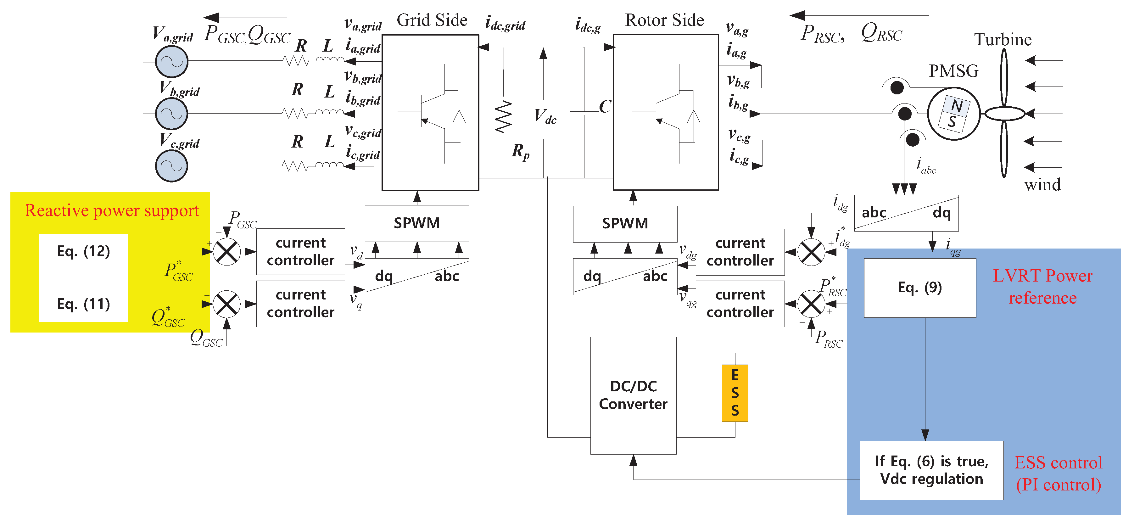
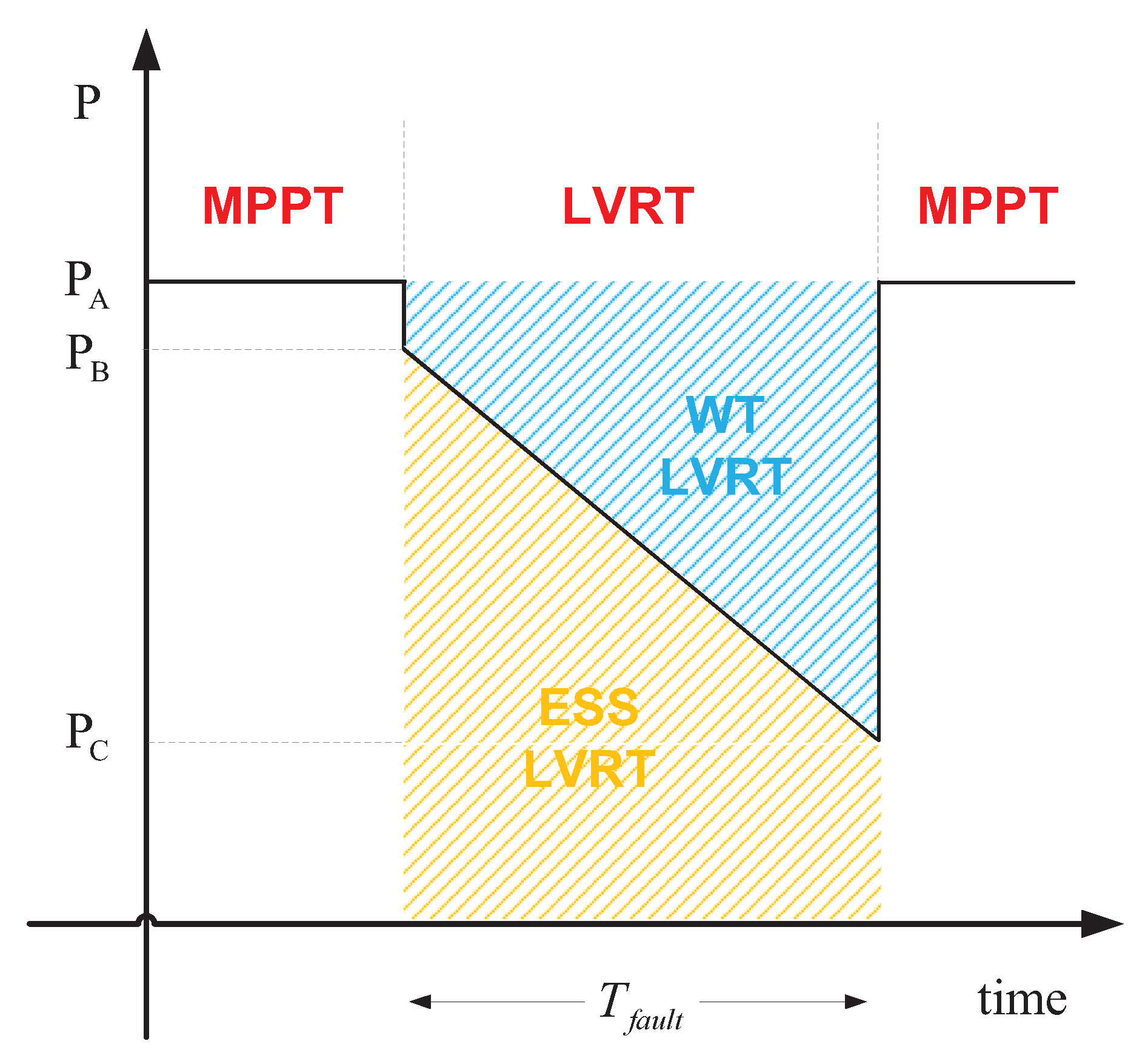
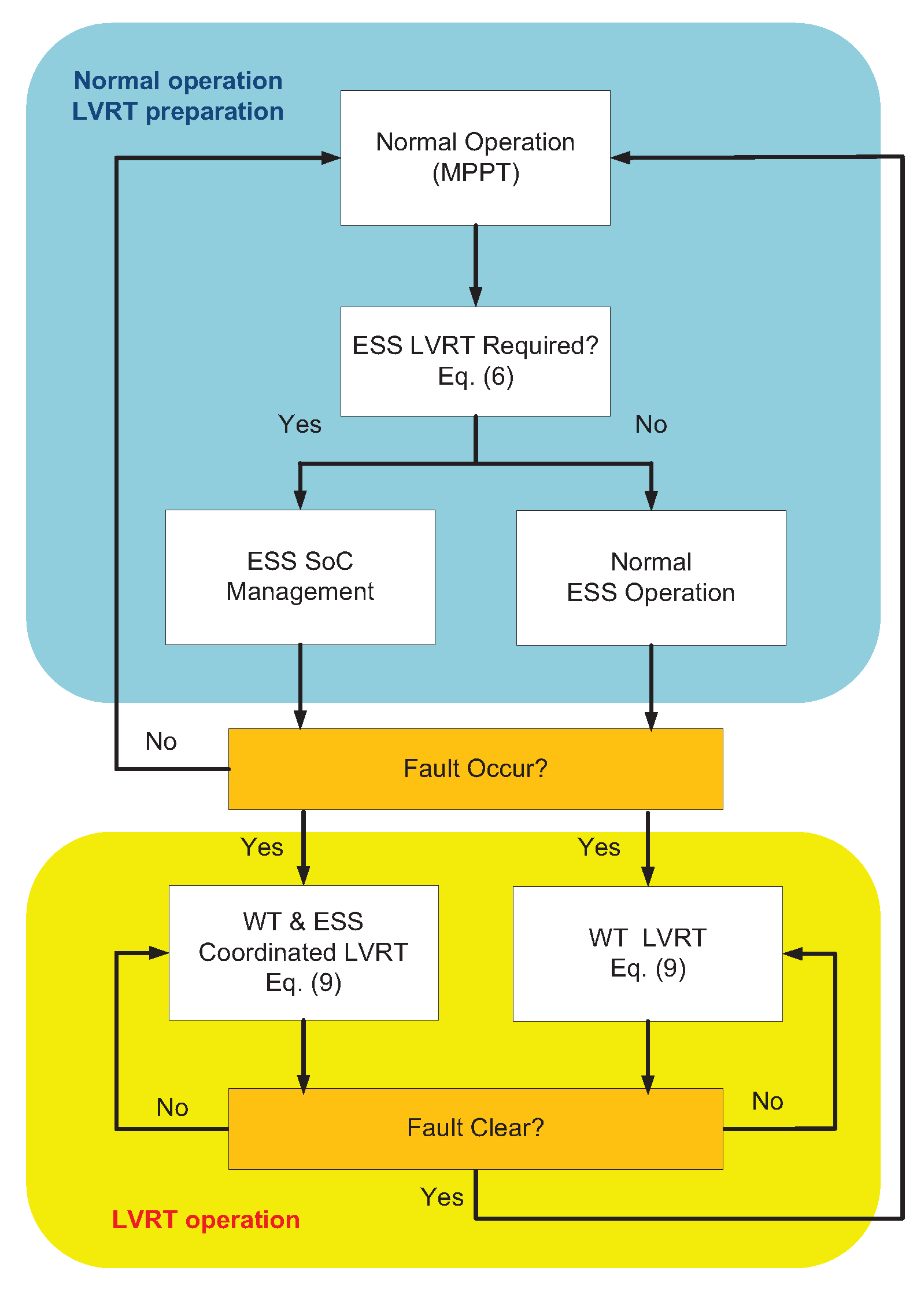
3. Proposed LVRT Control System

In this section, the overall LVRT control algorithm is described. The overall control structure is illustrated in Figure 2 including GSC, RSC, and ESS controls.The proposed method demonstrates that when the ESS is connected to a WPS, a coordinated form of control between the two is required for an efficient operation of the combined system. When the ESS SoC is low, the LVRT can be achieved by using just the ESS alone and when the WP produces low power at low wind speeds, the WT can reduce its power without increasing the dc link voltage significantly. However, the ESS can be used to achieve different objectives. Thus, it is not efficient to conserve the ESS capacity by limiting its SoC only during uncertain grid events. Moreover, when the WP produces large power at high wind speeds and the WPS operates near the rated rotor speed, it is not possible to achieve successful LVRT operation using the WPS alone when the rotor speed is greater than the speed limit. Thus, the ESS LVRT operation is required in order to help the WPS during LVRT. An ESS plays a very important role in many WT operations, especially at the time of a grid fault. Because the capacity of an ESS is limited and involves high installation costs, it is not cost-effective to limit the SoC range during normal operation; further, it is important to control the ESS using proper information from the WT operation. In the case of LVRT, the grid codes specify the fixed duration for which a WPS should be connected, and the ESS capacity required for LVRT operation can be obtained from current WT operation information. We analyzed the relationship between the ESS capacity required and WPS operation status and proposed a coordinated LVRT control method.

3.1. Pitch & Rotor Side Converter Controls

In previous studies, pitch and RSC controls (also called WT inertia control) were proposed [25] for LVRT control in a WT. These controls can be used for effective LVRT at normal and low wind speeds. However, when the WPS operates at high wind speeds and rotor speed is similar to the rated rotor speed, the rotor speed might be over its limit. Because many WPSs include ESSs for different WP applications, it would be more efficient to use the ESS properly. Thus, we formulated coordinated pitch and RSC controls by calculating an appropriate power reference during LVRT operation. As shown in Figure 3 the WP coefficient reduces as the pitch angles increases. Even though the pitch angle has a slow mechanical response, 10°/s in an emergency, it has the effect of decreasing the WP reference during the LVRT. Without pitch angle control, the power reference can change from A (MPPT) to B. We can modulate the power reference to decrease further at the time of a grid fault. However, it is quite complex and can result in violations of the speed limit. Therefore, we can define the power reference with respect to the pitch angle and it can be represented as shown in Figure 4 considering the maximum pitch angle response. We considered the grid fault duration as 0.625 s and the maximum pitch angle variation to be 6.25°/s. Therefore, the power reference can be defined as the profile from B to C considering a linear variation of the pitch angle. In this case, the upper portion of the power reduction can be regarded as the WT LVRT response and the bottom portion as the ESS-required LVRT response (Figure 4). By defining the power reference design in this manner, we can guarantee that the WT LVRT remains within the rotor speed limit and prepare the required ESS capacity for LVRT. Before we apply the proposed method, we can analyze whether the ESS LVRT response is required or not. Because the total energy required for the LVRT response can be regarded as the entire rectangular region in Figure 4, the following equation can be used to evaluate situations in which the ESS is required for a suitable LVRT response.
1 2 J ω l i m i t 2 ω m 2 < 0 T f a u l t P t d t ,
where T f a u l t is the fault duration which is defined as the grid code requires a WT to be connected. ω l i m i t denotes the maximum rotor speed limit. If the above equation is satisfied, then an ESS LVRT response is needed; the required ESS capacity can be obtained using the following equation.
E S S L V R T = 1 2 P B + P C T f a u l t ,
where E S S L V R T is the required ESS capacity for LVRT. B and D can be obtained by the following equations.
P B = 1 2 ρ A C p ω l i m i t , β v w i n d 3 , P C = 1 2 ρ A C p ω l i m i t , β m a x v w i n d 3 ,
where P B is the current MPPT power output and P D is the lowest power reference during LVRT. β m a x is the maximum achievable pitch angle when its value is increased in steps of 10°/s during LVRT. Thus, the RSC is controlled by following rules.
P R S C = P i n e r t i a , if Equation ( 6 ) is false , P c o o r d i n a t e , if Equation ( 6 ) is true ,
where
P i n e r t i a = k 1 e + k 2 e , P c o o r d i n a t e = P B + P C P B t / T f a u l t ,
and e is the dc link voltage error, e = V d c V d c and k 1 and k 2 are used for the proportional and integral gains, respectively. t is the time elapsed after the grid fault occurs. Thus, the RSC controls its power depending upon whether the ESS is required for LVRT. That is, when the ESS is not required for LVRT, P i n e r t i a is used for the RSC reference power and if the ESS is required, P c o o r d i n a t e is used.

3.2. Grid Side Converter & ESS Control

When a grid fault occurs, the WT produce reactive power according to the grid code requirement. We defined the reactive power reference by the following equation and the active power can be obtained from the reactive power definition.
Q G S C = 2 V s a g , if V s a g < 0.5 pu , 1 , if V s a g 0.5 pu ,
P G S C = 1 ( Q G S C ) 2 .
In some previous studies, the GSC was controlled during dc link regulation. Because the GSC should satisfy the grid requirement of reactive power support during LVRT, it is better to focus on the objective of reactive power control. When the WT does not need the ESS control for the LVRT at low or normal wind speeds, the RSC is controlled to regulate the dc link voltage as shown in Equation (11). However, when the WT needs ESS control during a grid fault, the ESS is controlled to regulate the dc link voltage instead of the RSC, and the RSC is controlled to track the power reference according to Equation (11). The overall control flow chart is described in Figure 5. Therefore, the role of the dc link voltage regulation is assigned appropriately in the case of any grid fault.

4. Simulation Result

The proposed LVRT control method was validated using MATLAB/Simulink, SimPowerSystems. The WT and ESS are modelled by detailed circuit model and the simulation time step is 50 microseconds. Since the simulation time is about 3 s, the data size is 60,000 for respective values of voltage and current. The fixed step solver with the sampling time as 50 microseconds is used. The capacity of a PMSG WT is 1.6 MW while the ESS energy capacity is 1 kWh. We considered an 80% voltage sag condition for a PCC duration of 0.625 s in cases with the strictest regulation, such as those of Ireland. The overall system parameters are described in Table 1. We considered the performance of typical LVRT methods with or without additional devices such as an ESS. Without this additional device, WT LVRT operation is handled only by pitch and converter controls whereas with additional devices, a chopper can be used. Even though a chopper can successfully limit dc link voltage variation, it just dissipates the produced WT power. Moreover, it experiences dc link voltage fluctuations owing to its operational characteristics.

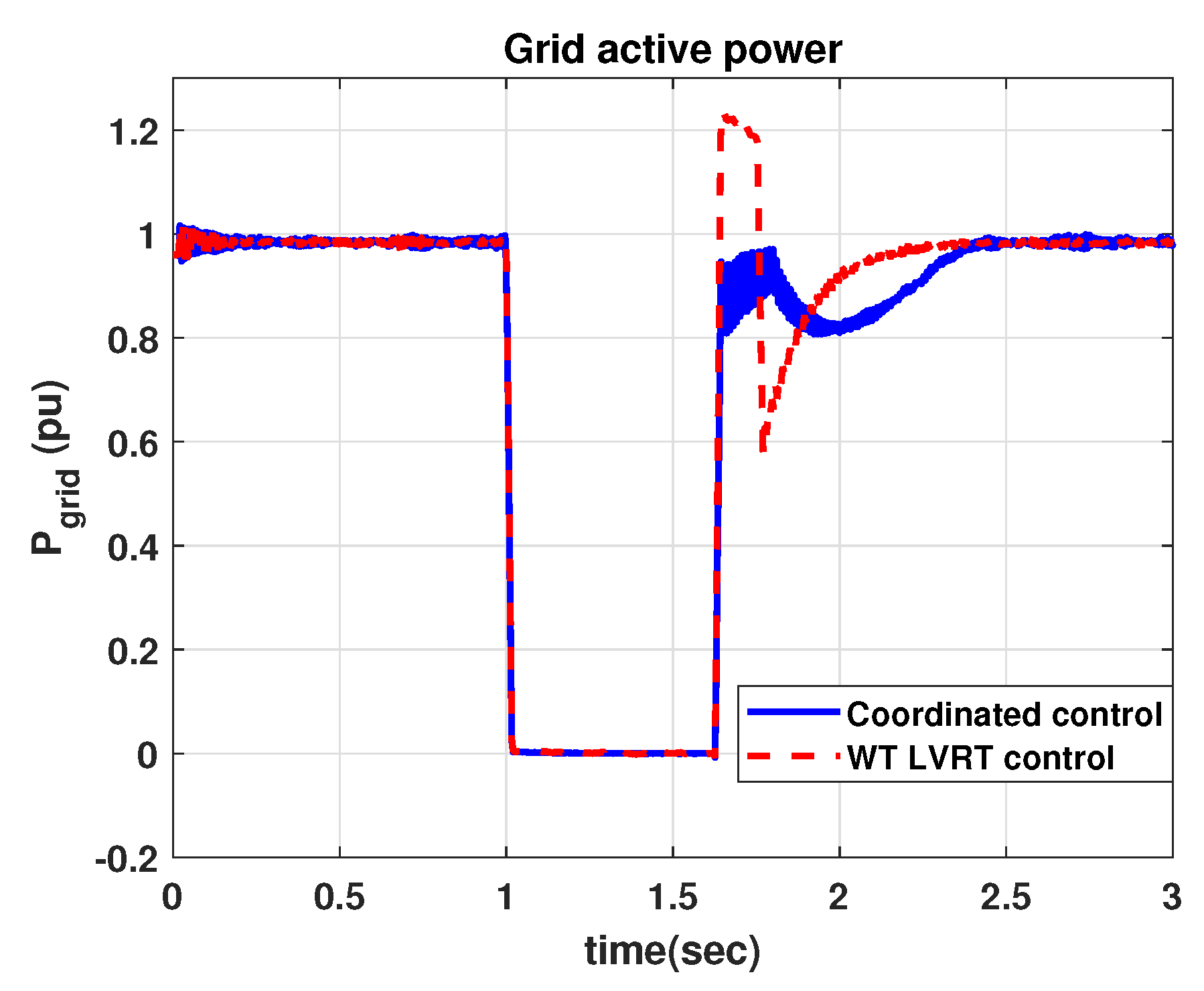
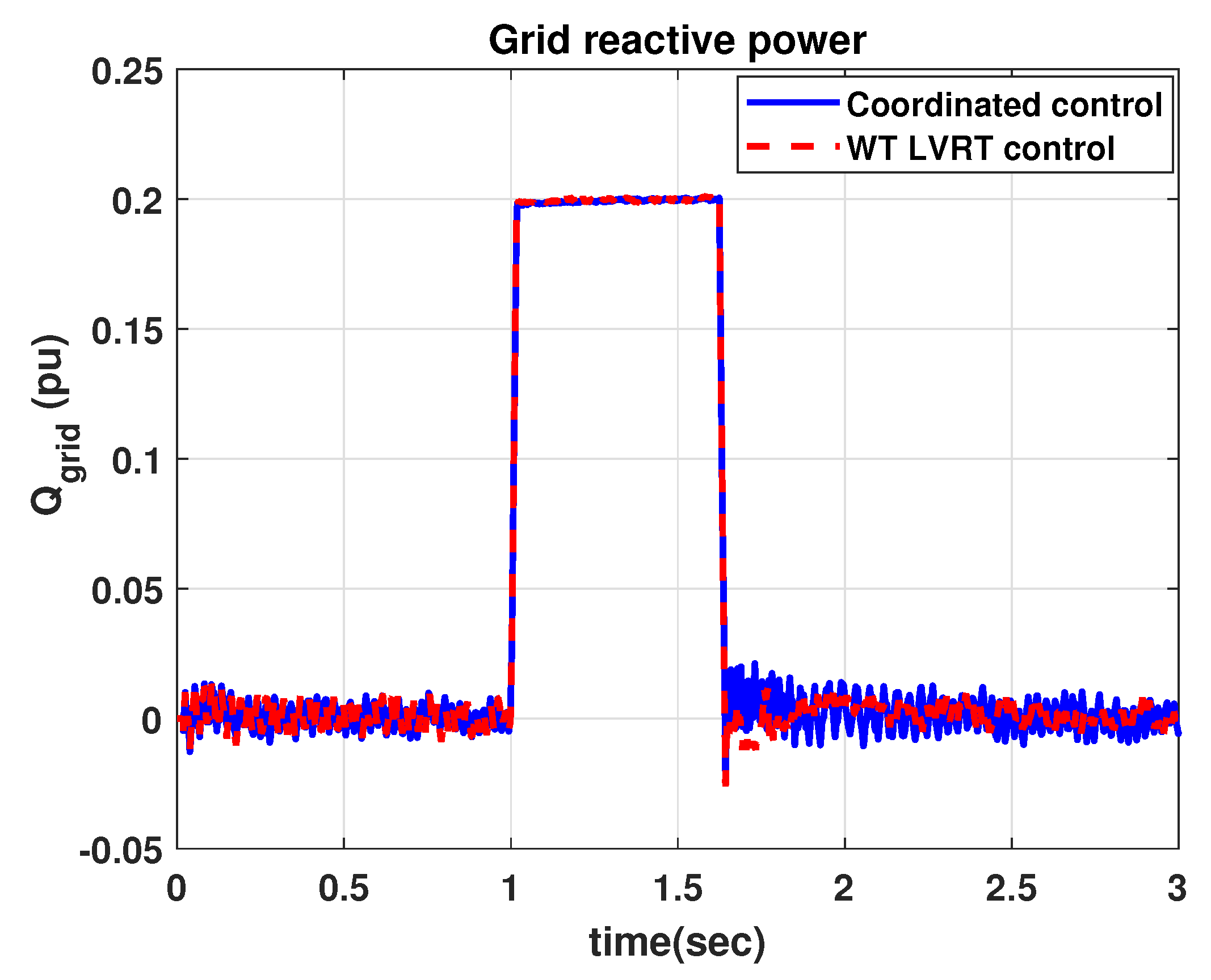
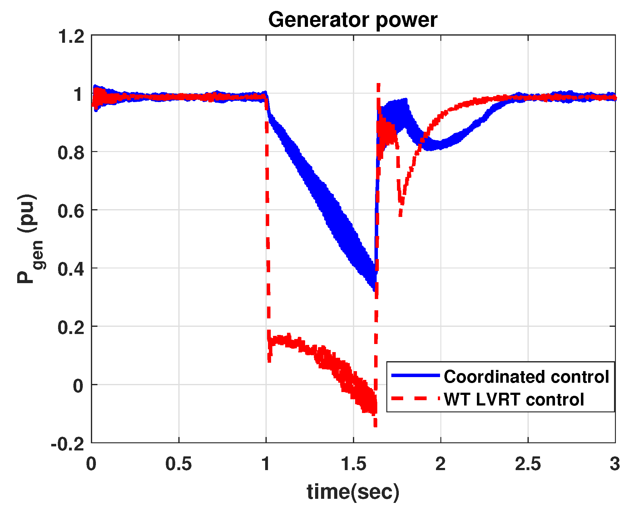
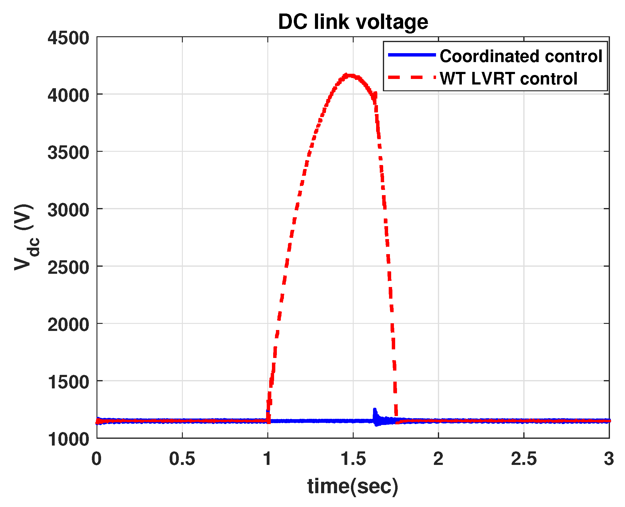
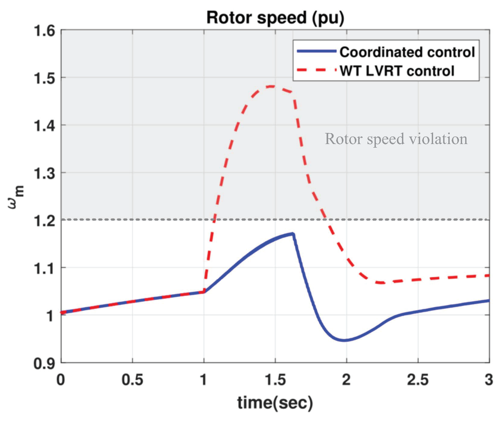
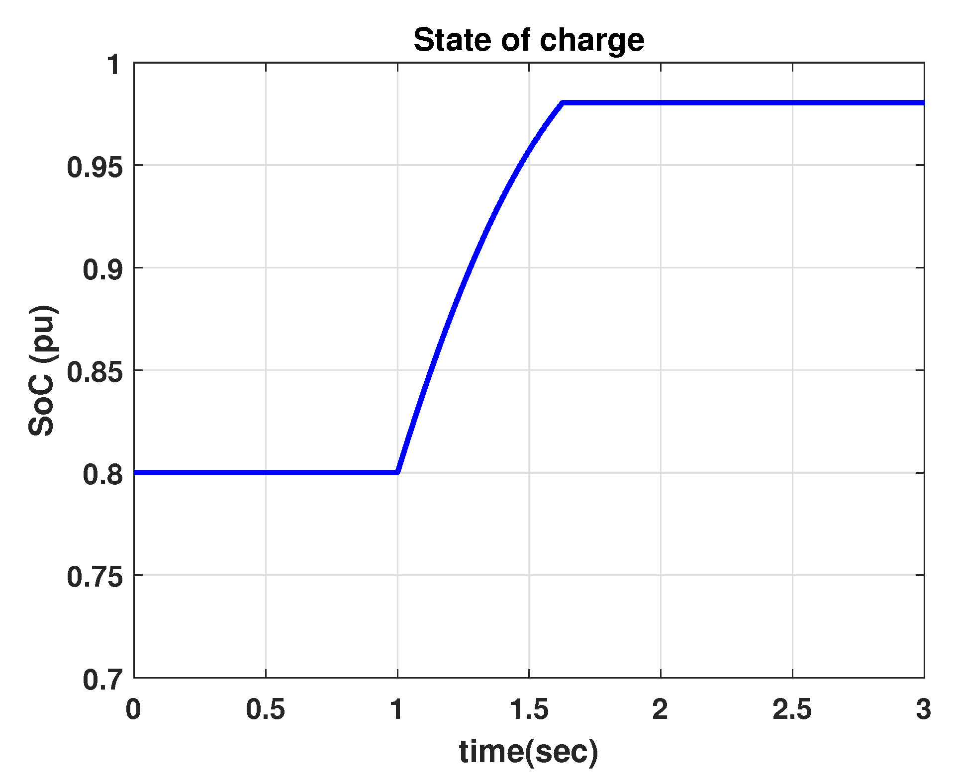
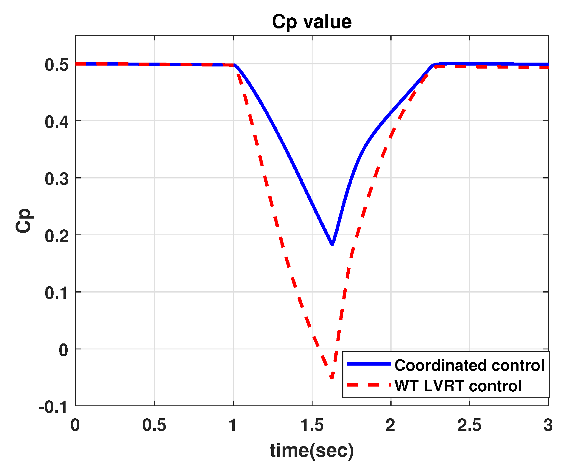
4.1. Comparison with WT LVRT

In this study, we first considered LVRT performance without additional devices. In this case, the WT must take up the entire LVRT operation burden by controlling the pitch angle and rotor speed. At low wind speeds, this control method can handle LVRT operation, by itself. However, at high wind speeds, it is impossible to satisfy the LVRT grid code while meeting its rotor speed limit constraint.
The performance of the proposed LVRT method is illustrated from Figure 6, Figure 7, Figure 8, Figure 9, Figure 10, Figure 11 and Figure 12. At 80 % voltage sag, the WT should limit the active power to zero and supply full reactive power to the grid. As shown in Figure 6, the WT produced zero active power from the GSC (can be considered as active power to grid) and a reactive power of 0.2 pu during the fault period as shown in Figure 7. A different grid active power profile was observed immediately after the duration of the grid fault. This is because of the GSC control law where the GSC has different power references owing to the difference in the dc link voltage violation. However, we focused more on the behavior during the grid fault and it acts similarly in the two methods during the duration of the fault. Because the grid voltage is 0.2 pu, reactive power current from the GSC is 1 pu, which is the maximum achievable current. Thus, the GSC successfully achieved LVRT control during the fault; that is, full reactive power production was obtained. The results of the two different methods have similar behaviors during the grid fault. As shown in Figure 8, the RSC (can be considered generator power) produces a predefined power considering the pitch angle and the maximum rotor speed limit of the proposed method. Hence, it can be stated that the proposed method realized a suitable power reduction because of the WT during the fault period. However, in the case of WT LVRT control, it tried to produce zero active power to regulate the dc link voltage. The tracking performance was not good in WT LVRT control, and resulted in a high deviation of the dc link voltage as shown in Figure 9. In the proposed method, the dc link voltage regulation was quite improved. The dc link voltage regulation could be further improved in WT LVRT control by modulating the controller or by using nonlinear controller. However, this is not the only problem. The rotor speed was also within the limit as shown in Figure 10 in the proposed method, but, in the case of WT LVRT control, the rotor speed violated its limit. Thus, even though the WT LVRT control is improved, the rotor speed violation will not be eliminated. Because the proposed method calculates the amount of power reduction during the grid voltage sag, the required ESS capacity can be properly conserved. Thus, the SoC requirement for grid faults can be efficiently satisfied using the WT and ESS scheduling operation. The ESS scheduling operation can be implemented for several objectives, such as the smoothing of WP fluctuations and peak load reduction. These operations, however, are out of the scope of this study. However, we defined the required ESS capacity for the LVRT and it can be used as a constraint in that optimization problem. Thus, defining the required ESS capacity for LVRT is meaningful for the efficient operation of the WT during normal and LVRT operation. In Figure 11, the ESS SoC was within its limit of 1 pu in the proposed method. In terms of the power coefficient, the proposed method had a higher value during the grid fault. It can be stated that the proposed method was better in terms of energy harvesting during the grid fault because the ESS never dissipated the energy difference to the chopper.

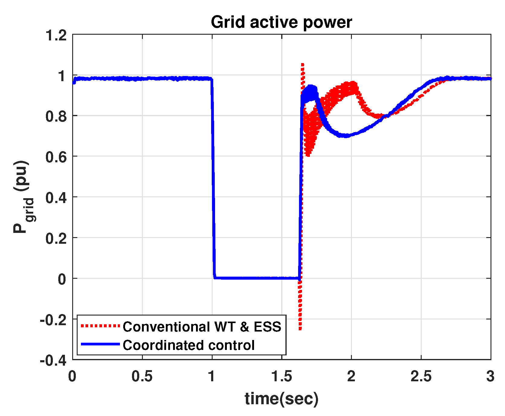
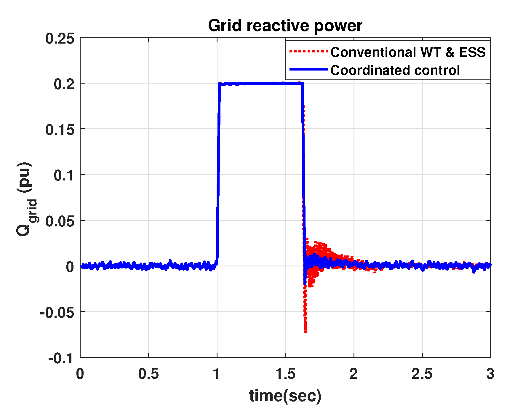
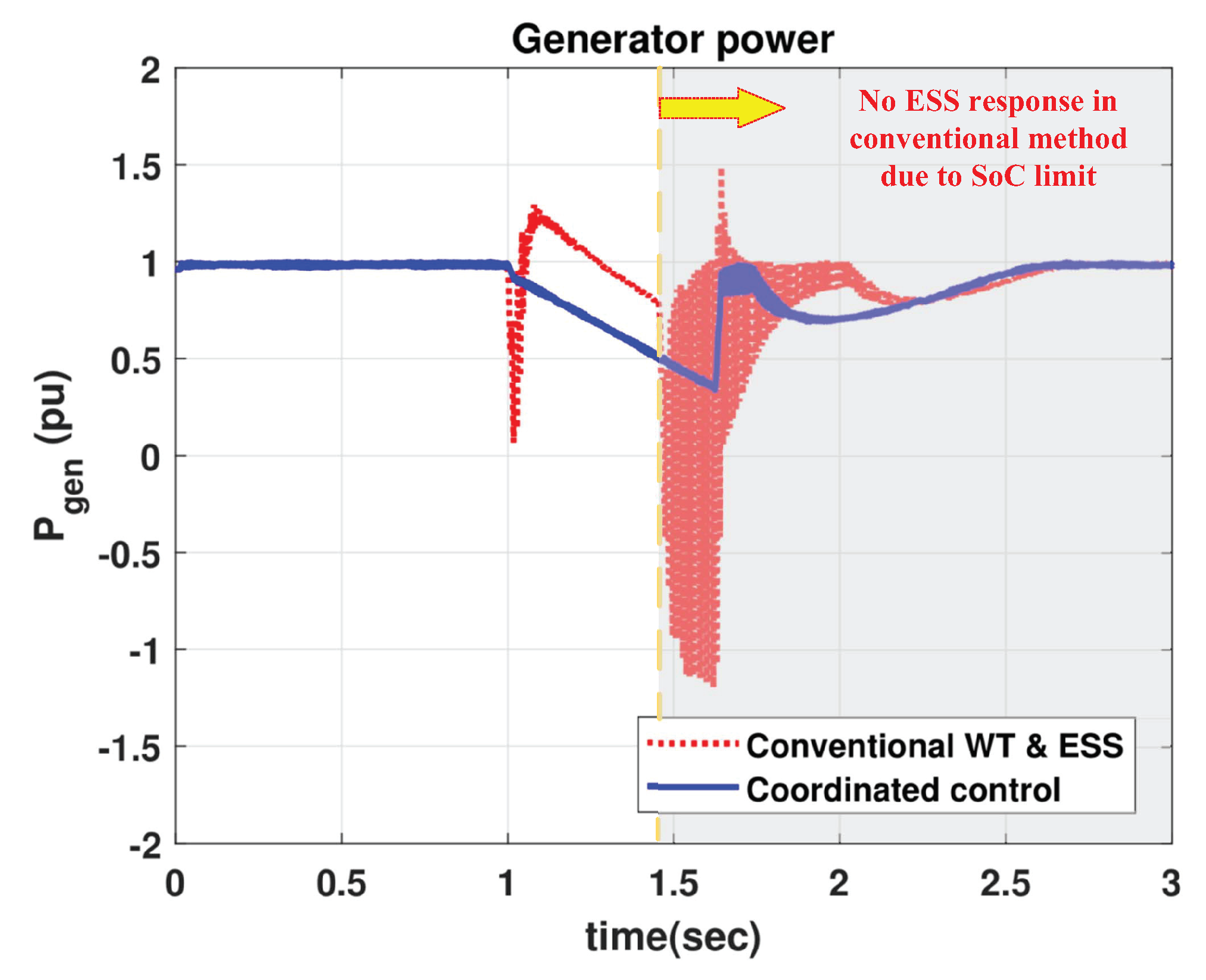
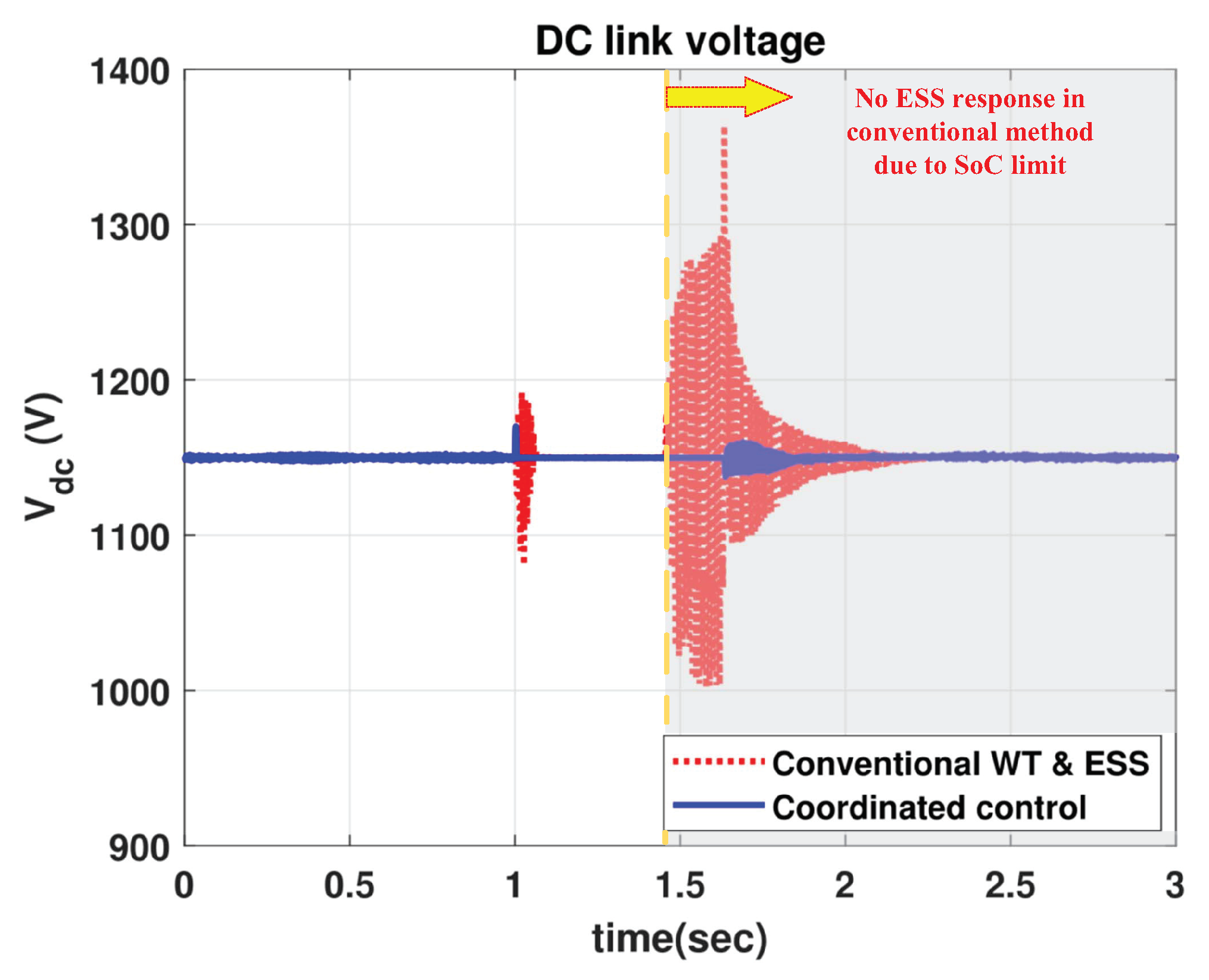
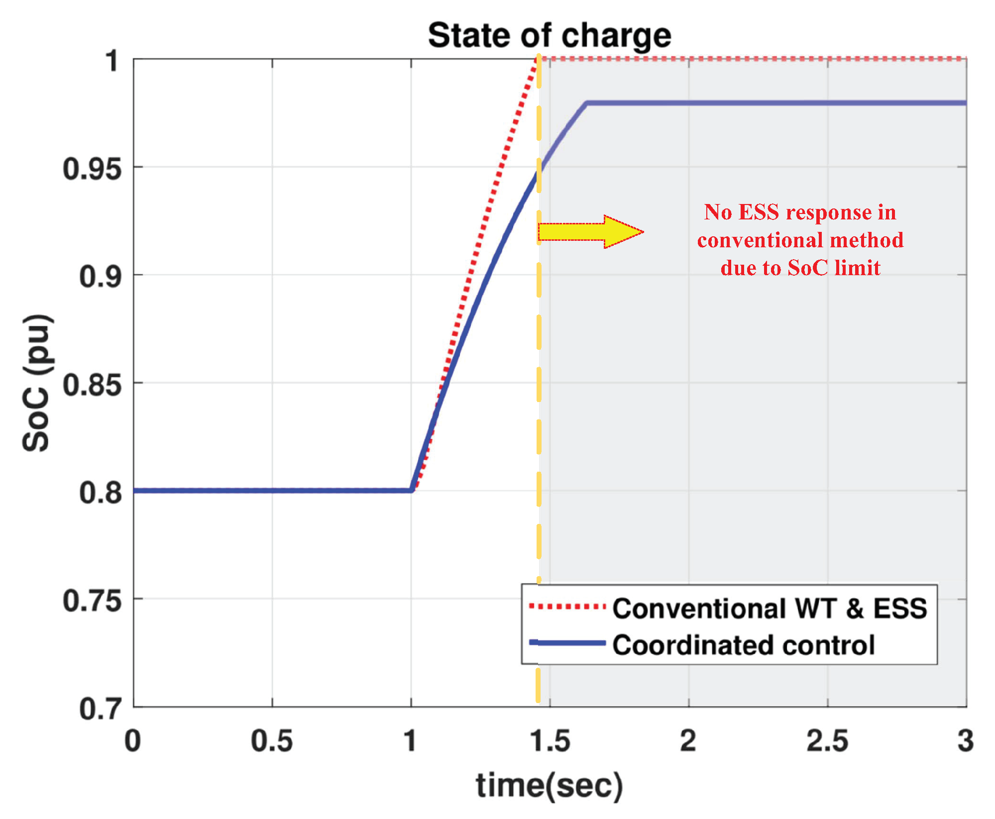
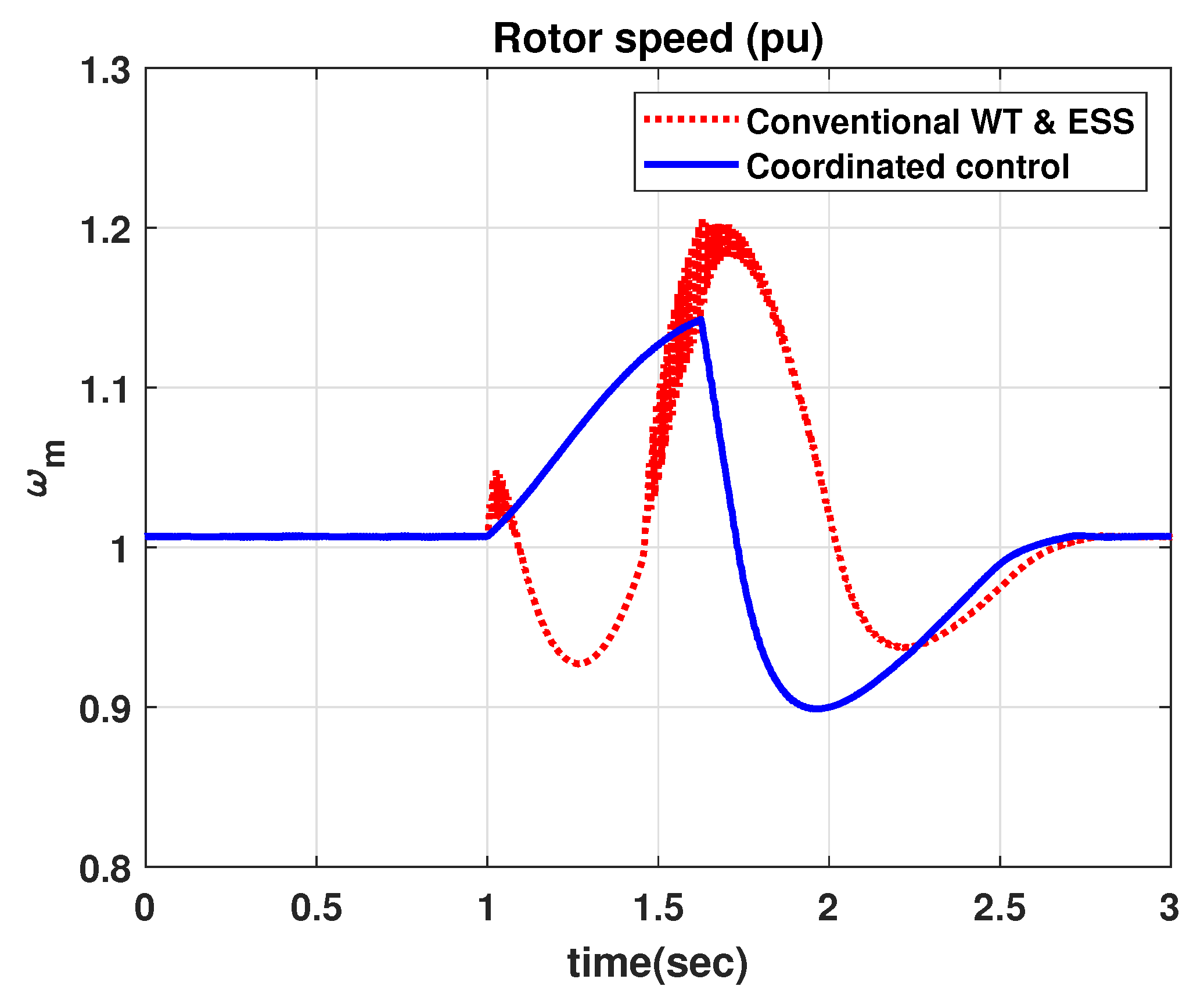
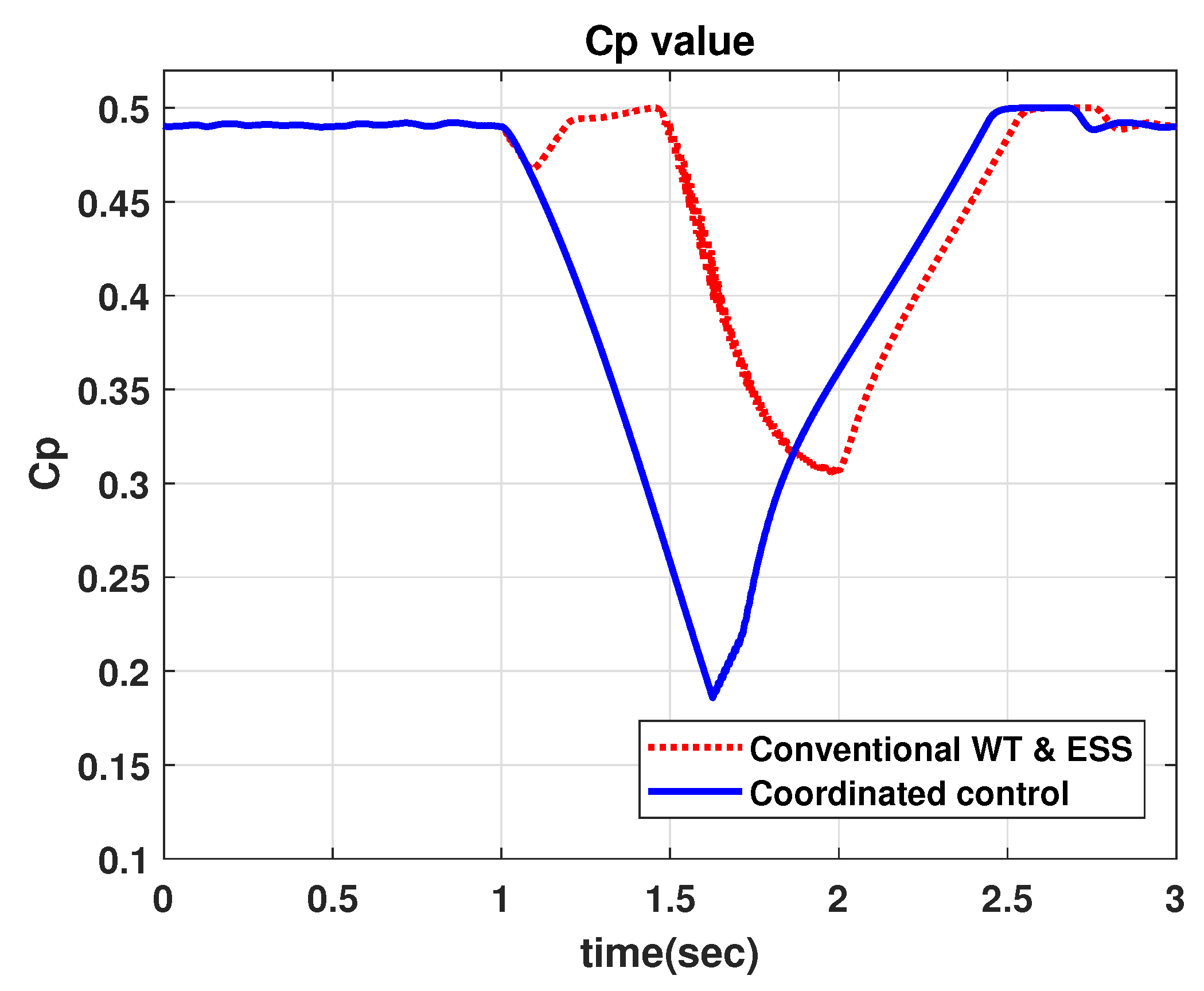
4.2. Comparison with Conventional WT & ESS for LVRT

Next, we considered LVRT performance with an ESS. In this case, the ESS will help the WT fulfill LVRT operation. Normally, the ESS can effectively take on the entire burden of LVRT operation. However, the ESS control is more efficient when it is utilized for multiple objectives. If the ESS is used for multiple objectives, it is hard to assume its SoC is near the value of 0.5 pu. To highlight the effectiveness of the proposed method, we considered the case when the ESS SoC is 0.8 pu. Conventional methods control the ESS by regulating the dc link voltage. From Figure 13, Figure 14, Figure 15, Figure 16, Figure 17, Figure 18 and Figure 19, the comparison of the performance between the conventional WT and ESS LVRT control and the proposed coordinated LVRT method is illustrated. As shown in Figure 13, the WT produced zero active power from the GSC and a reactive power of 0.2 pu during the fault period as shown in Figure 14. During the grid fault, the GSC was controlled to produce zero active power. After the grid fault, the GSC was controlled to regulate the dc link voltage. In Figure 15, the RSC was controlled to regulate the dc link voltage during the grid fault. The active power from the RSC oscillated greatly because of the variation in the dc link voltage as shown in Figure 16. This was because of the ESS SoC limit; the ESS SoC approached its limit at around 1.4 s as shown in Figure 17. Moreover, the rotor speed was violated in the conventional method; this violation is another weakness of the conventional method as shown in Figure 18. Figure 19 shows the power coefficient variation during the grid fault. Therefore, we conclude that the conventional method can not effectively handle the operational constraints of the WT rotor speed and the ESS SoC especially when the wind speed is high during the grid fault. We validated the benefits of the proposed method considering two case studies which illustrate the constraints violations during grid fault. Previous coordinated LVRT methods [22,23] using an ESS can result in constraints violation or can require additional device when there is high wind speed and the ESS SoC is close to 1 pu.

5. Conclusions

In this investigation, we proposed a coordinated LVRT control method using a PMSG WT and an ESS. Many previous studies on LVRT focused on improving its transient response. However, we focused on coordinating the WPS (pitch and inertia modulated) and ESS controls. Before applying the coordinated control method, we evaluated whether an ESS LVRT response is required using power equation analysis. At high wind speeds, an ESS LVRT response is required in addition to the WPS LVRT response to account for the rotor speed limit and converter current limits. If no ESS LVRT response is required, the WPS LVRT response is enough to handle the LVRT during the grid fault. When an ESS LVRT response is required, the power reference considering the pitch dynamics and rotor speed limit is used to evaluate the proper power reference of each unit in the proposed coordinated LVRT method. Using the proposed method, the ESS required power output for LVRT support was obtained. Thus, the ESS energy was conserved according to the WPS operational status and it can result in more cost effective ESS SoC management. From the two case studies, we validated the effectiveness of the proposed method by satisfying the operational constraints of the WT rotor speed limit and the ESS SoC limit.

Author Contributions

C.K. designed the algorithm and developed the simulation; Y.G. provided guidance in designing the algorithm; H.Z. and W.K. verified the simulation model and results; and all authors reviewed and approved the manuscript. All authors have read and agreed to the published version of the manuscript.

Funding

This research was supported by Energy Cloud R&D Program through the National Research Foundation of Korea (NRF) funded by the Ministry of Science, ICT (NRF-2019M3F2A1073313).

Conflicts of Interest

The authors declare that they have no conflict of interest.

Abbreviations

The following abbreviations are used in this manuscript:
DFIGDoubly-fed induction generator
ESSEnergy storage system
GSCGrid-side converter
LVRTLow-voltage ride through
MPPTMaximum power point tracking
PCCPoint of common coupling
PIProportional-integral
PMSGPermanent magnet synchronous generator
RSCRotor-side converter
SoCState of charge
WPWind power
WPSWind power system
WTWind turbine

References

  1. Chinchilla, M.; Arnaltes, S.; Burgos, J.C. Control of permanentmagnet generators applied to variable-speed wind-energy systems connected to the grid. IEEE Trans. Energy Convers. 2006, 21, 130–135. [Google Scholar] [CrossRef] [Green Version]
  2. Polinder, H.; Van der Pijl, F.F.A.; Vilder, D.; Tavner, P.J. Comparison of direct-drive and geared generator concepts for wind turbines. IEEE Trans. Energy Convers. 2006, 21, 725–733. [Google Scholar] [CrossRef] [Green Version]
  3. Gui, Y.; Xiongfei, W.; Heng, W.; Blaabjerg, F. Voltage modulated direct power control for a weak grid-connected voltage source inverters. IEEE Trans. Power Electron. 2019, 34, 11383–11395. [Google Scholar] [CrossRef] [Green Version]
  4. Gui, Y.; Wang, X.; Blaabjerg, F.; Pan, D. Control of grid-connected voltage-source converters: The relationship between direct-power control and vector-current control. IEEE Ind. Electron. Mag. 2019, 13, 31–40. [Google Scholar] [CrossRef] [Green Version]
  5. Kim, C.; Gui, Y.; Chung, C.C. Maximum power point tracking of a wind power plant with predictive gradient ascent method. IEEE Trans. Sustain. Energy 2017, 8, 685–694. [Google Scholar] [CrossRef]
  6. Kim, J.; Muljadi, E.; Gevorgian, V.; Hoke, A. Dynamic capabilities of an energy storage-embedded dfig system. IEEE Trans. Ind. Appl. 2019, 55, 4124–4134. [Google Scholar] [CrossRef]
  7. Kim, C.; Muljadi, E.; Chung, C.C. Coordinated control of wind turbine and energy storage system for reducing wind power fluctuation. Energies 2018, 11, 52. [Google Scholar] [CrossRef] [Green Version]
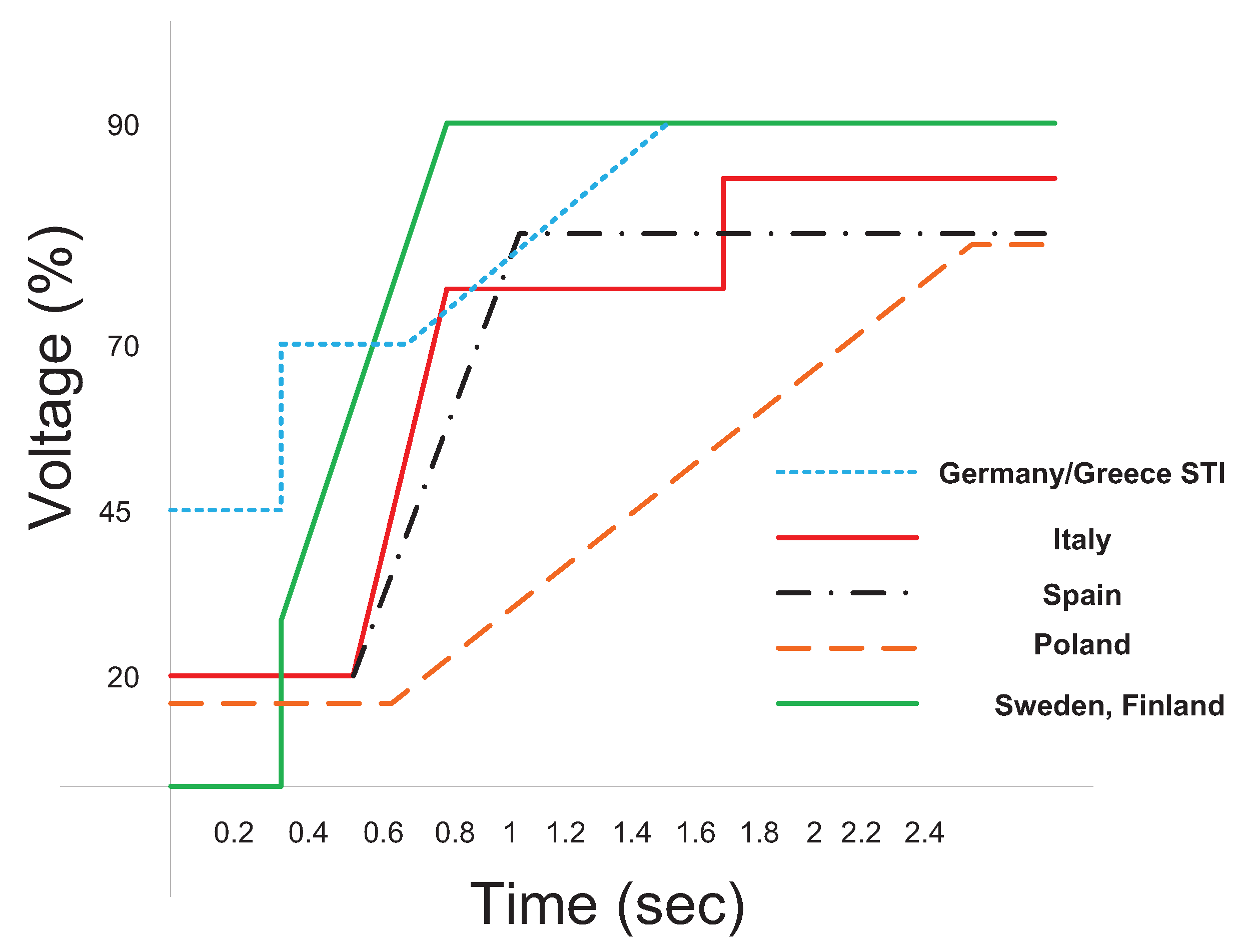
  8. Tsili, M.; Papathanassiou, S. A review of grid code technical requirements for wind farms. IET Renew. Power Gener. 2009, 3, 308–332. [Google Scholar] [CrossRef]
  9. Marmouh, S.; Boutoubat, M.; Mokrani, L.; Machmoum, M. A coordinated control and management strategy of a wind energy conversion system for a universal low-voltage ride-through capability. Int. Trans. Electr. Energy Syst. 2019, 29, e12035. [Google Scholar] [CrossRef]
  10. Mahela, O.P.; Gupta, N.; Khosravy, M.; Patel, N. Comprehensive overview of low voltage ride through methods of grid integrated wind generator. IEEE Access 2019, 7, 99299–99326. [Google Scholar] [CrossRef]
  11. Saccomando, G.; Svensson, J.; Sannino, A. Improving voltage disturbance rejection for variable-speed wind turbines. IEEE Trans. Energy Convers. 2002, 17, 422–428. [Google Scholar] [CrossRef]
  12. Mullane, A.; Lightbody, G.; Yacamini, R. Wind-turbine fault ridethrough enhancement. IEEE Trans. Power Syst. 2005, 20, 1929–1937. [Google Scholar] [CrossRef]
  13. Matas, J.; Castilla, M.; Guerrero, J.M.; Garcia de Vicuna, L.; Miret, J. Feedback linearization of direct-drive synchronous wind-turbines via a sliding mode approach. IEEE Trans. Power Electron. 2008, 23, 1093–1103. [Google Scholar] [CrossRef]
  14. Kim, C.; Gui, Y.; Chung, C.C. A coordinated lvrt control for pmsg wind turbine. IFAC-PapersOnLine 2017, 50, 8758–8763. [Google Scholar] [CrossRef]
  15. Conroy, J.F.; Watson, R. Low-voltage ride-through of a full converter wind turbine with permanent magnet generator. IET Renew. Power Gener. 2007, 1, 182–189. [Google Scholar] [CrossRef]
  16. Alepuz, S.; Calle, A.; Busquets-Monge, S.; Kouro, S.; Wu, B. Use of stored energy in PMSG rotor inertia for low-voltage ride-through in back-to-back NPC converter-based wind power systems. IEEE Trans. Ind. Electron. 2013, 60, 1787–1796. [Google Scholar] [CrossRef]
  17. Kim, K.-H.; Jeung, Y.-C.; Lee, D.-C.; Kim, H.-G. LVRT scheme of PMSG wind power systems based on feedback linearization. IEEE Trans. Power Electron. 2012, 27, 2376–2384. [Google Scholar] [CrossRef]
  18. Nasiri, M.; Mobayen, S.; Zhu, Q.M. Super-twisting sliding mode control for gearless pmsg-based wind turbine. Complexity 2019, 2019. [Google Scholar] [CrossRef]
  19. Abbey, C.; Joos, G. Supercapacitor energy storage for wind energy applications. IEEE Trans. Ind. Appl. 2007, 43, 769–776. [Google Scholar] [CrossRef]
  20. Wang, W.; Ge, B.; Bi, D.; Qin, M.; Liu, W. Energy storage based LVRT and stabilizing power control for direct-drive wind power system. In Proceedings of the 2010 International Conference on Power System Technology, Hangzhou, China, 24–28 October 2010. [Google Scholar]
  21. Liu, J.; Wei, Y.; Jiakun, F.; Jinyu, W.; Shijie, C. Stability analysis and energy storage-based solution of wind farm during low voltage ride through. Int. J. Electr. Power Energy Syst. 2018, 3, 75–84. [Google Scholar] [CrossRef]
  22. Yao, J.; Jiawei, L.; Lisha, G.; Ruikuo, L.; Depeng, X. Coordinated control of a hybrid wind farm with pmsg and fsig during asymmetrical grid fault. Int. J. Electr. Power Energy Syst. 2018, 3, 287–300. [Google Scholar] [CrossRef]
  23. Li, J.; Wang, N.; Zhou, D.; Hu, W.; Huang, Q.; Chen, Z.; Blaabjerg, F. Optimal reactive power dispatch of permanent magnet synchronous generator-based wind farm considering levelised production cost minimisation. Renew. Energy 2020, 3, 1–12. [Google Scholar] [CrossRef]
  24. Haque, M.E.; Negnevitsky, M.; Muttaqi, K. A novel control strategy for a variable speed wind turbine with a permanent magnet synchronous generator. In Proceedings of the 2008 IEEE Industry Applications Society Annual Meeting, Edmonton, AB, Canada, 5–9 October 2008. [Google Scholar]
  25. Nasiri, M.; Milimonfared, J.; Fathi, S.H. A review of low-voltage ride-through enhancement methods for permanent magnet synchronous generator based wind turbines. Renew. Sustain. Energy Rev. 2015, 47, 399–415. [Google Scholar] [CrossRef]
Figure 1. Limit curves for the voltage to allow generator disconnection.
Applsci 10 03085 g001
Figure 2. Overall control block diagram of the generator and GSC.
Applsci 10 03085 g002
Figure 3. Power coefficient variation according to pitch angle. (A:maximum power point tracking (MPPT) at β = 0 ° , B and C represent the power reference at a rotor speed of 1.2pu with different pitch angles).
Applsci 10 03085 g003
Figure 4. Power reference variation (the wind turbine (WT) LVRT region reflects reduced power from the WPS while the energy storage system (ESS) low-voltage ride through (LVRT) region describes the charged energy in the ESS).
Applsci 10 03085 g004
Figure 5. Flow chart of GSC switching operations during normal and fault operation.
Applsci 10 03085 g005
Figure 6. Grid active power during a balanced voltage sag (80%).
Applsci 10 03085 g006
Figure 7. Grid reactive power during a balanced voltage sag (80%).
Applsci 10 03085 g007
Figure 8. Generator active power during a balanced voltage sag (80%).
Applsci 10 03085 g008
Figure 9. DC link voltage during a balanced voltage sag (80%).
Applsci 10 03085 g009
Figure 10. Rotor speed variation during a balanced voltage sag (80%).
Applsci 10 03085 g010
Figure 11. State of charge (SoC) during a balanced voltage sag (80%) (proposed coordinated control).
Applsci 10 03085 g011
Figure 12. Power coefficient variation during a balanced voltage sag (80%).
Applsci 10 03085 g012
Figure 13. Grid active power during a balanced voltage sag (80%).
Applsci 10 03085 g013
Figure 14. Grid reactive power during a balanced voltage sag (80%).
Applsci 10 03085 g014
Figure 15. Generator active power during a balanced voltage sag (80%).
Applsci 10 03085 g015
Figure 16. dc link voltage during a balanced voltage sag (80%).
Applsci 10 03085 g016
Figure 17. SoC during a balanced voltage sag (80%).
Applsci 10 03085 g017
Figure 18. Rotor speed variation during a balanced voltage sag (80%).
Applsci 10 03085 g018
Figure 19. Power coefficient variation during a balanced voltage sag (80%).
Applsci 10 03085 g019
Table 1. System parameters used in simulation.
ParameterValueUnit
Rated power1.63MW
Rated wind speed12m/s
Max. power coeff.0.5
Optimal tip speed ratio9.9495
Blade radius33.05m
Air density1.12 kg / m 3
Max. rotor speed1.2pu
DC link voltage1150V
Turbine inertia6500 kgm 2
ESS capacity1kWh

