Accident Reconstruction of Damaged Human Body Using MDCT and Computer Numerical Analysis


Abstract
1. Introduction
2. Background of Damaged Human Body
3. Reconstruction of the Damaged Human Model
4. Analysis of Damage Mechanism Using ADINA
4.1. Pre-Processing of Computational Numerical Analysis
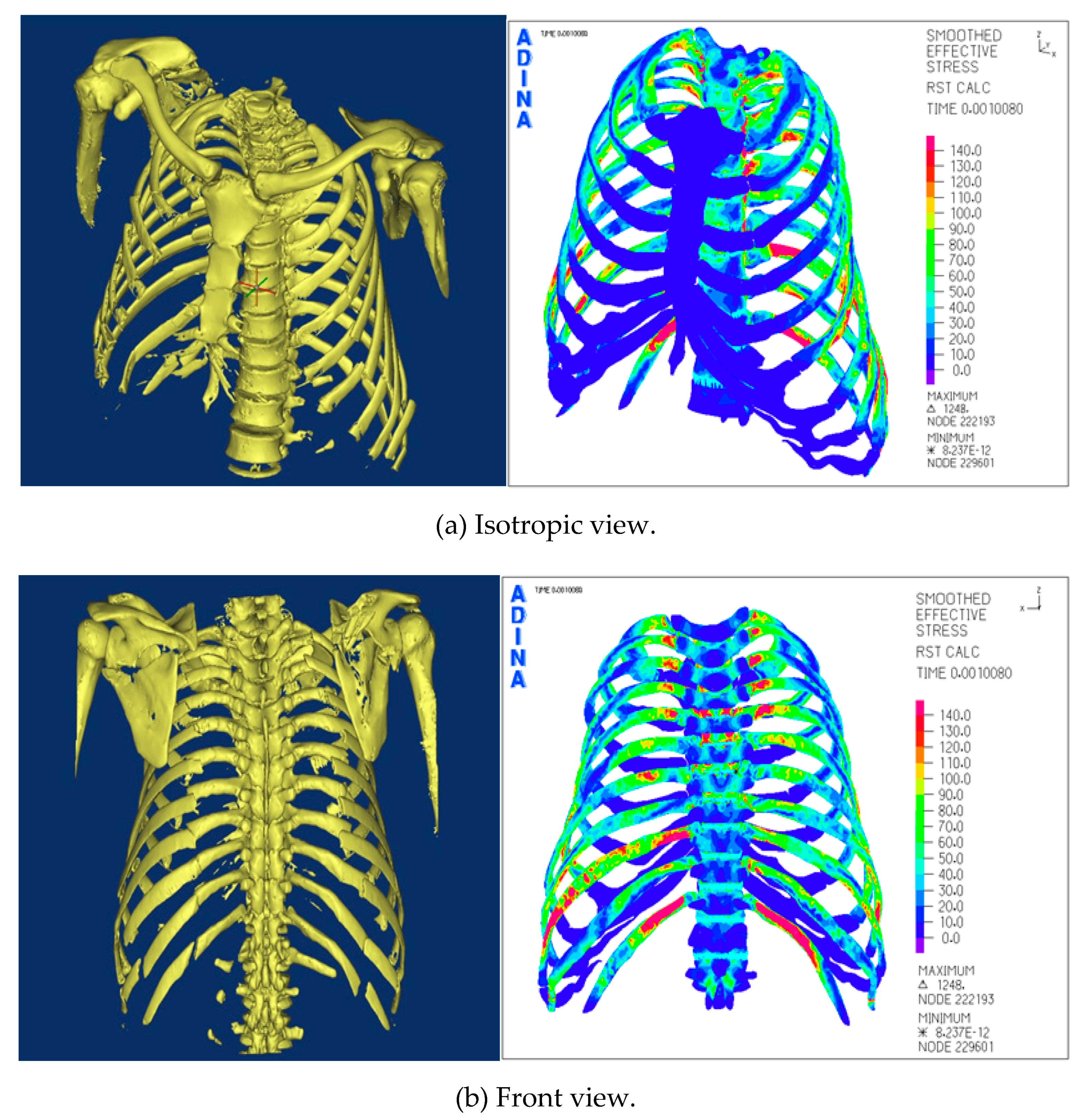
4.2. Post-Processing of Computational Numerical Analysis
5. Conclusions
Funding
Conflicts of Interest
References
- Greer, A. Numerical Modeling for the Prediction of Primary Blast Injury to the Lung. Master’s Thesis, University of Waterloo, Waterloo, ON, Canada, January 2007. [Google Scholar]
- Bass, C.R.; Salzar, R.; Davis, M.; Lucas, S.; Donnellan, L.; Folk, B. Injury risk in behind armor blunt thoracic trauma. Int. J. Occup. Saf. Ergon. 2006, 12, 429–442. [Google Scholar] [CrossRef] [PubMed]
- Dupre, S. Modelisation en Elements Finis du Complexe de L’epaule et Simulation de Sa reponse a un Choc Lateral. Ph.D. Thesis, L’institut National des Sciences Applique’s de Lyon, Villeurbanne, France, 2007. [Google Scholar]
- Stemper, B.D.; Board, D.; Yoganandan, N.; Wolfla, C.E. Biomechanical properties of human thoracic spine disc segments. J. Craniovertebral Junction Spine 2010, 1, 18–22. [Google Scholar]
- Lau, A.G.; Oyen, M.L.; Kent, R.W.; Murakami, D.; Torigaki, T. Indentation stiffness of aging human costal cartilage. Acta Biomater. 2008, 4, 97–103. [Google Scholar] [CrossRef] [PubMed]
- Kemper, A.R.; McNally, C.; Kennedy, E.A.; Manoogian, S.J.; Rath, A.L.; Nq, T.P.; Stitzel, J.D.; Smith, E.P.; Duma, S.M.; Matsuoka, F. Material properties of human rib cortical bone from dynamic tension coupon testing. Stapp. Car. Crash J. 2005, 49, 199–230. [Google Scholar] [PubMed]


| Young’s Modulus | Density (kg/m3) | Poisson’s Ratio | Yield Strength (MPa) | Tension Strength (MPa) | |
|---|---|---|---|---|---|
| Rib | 13.9 GPa | 1561 | 0.3 | 93.9 | 124.2 |
| Sternum | 3.51 GPa | 1354 | 0.387 | 34.48 | 48.27 |
| Vertebra | 4.67 GPa | 1500 | 0.3 | 52.62 | 69.06 |
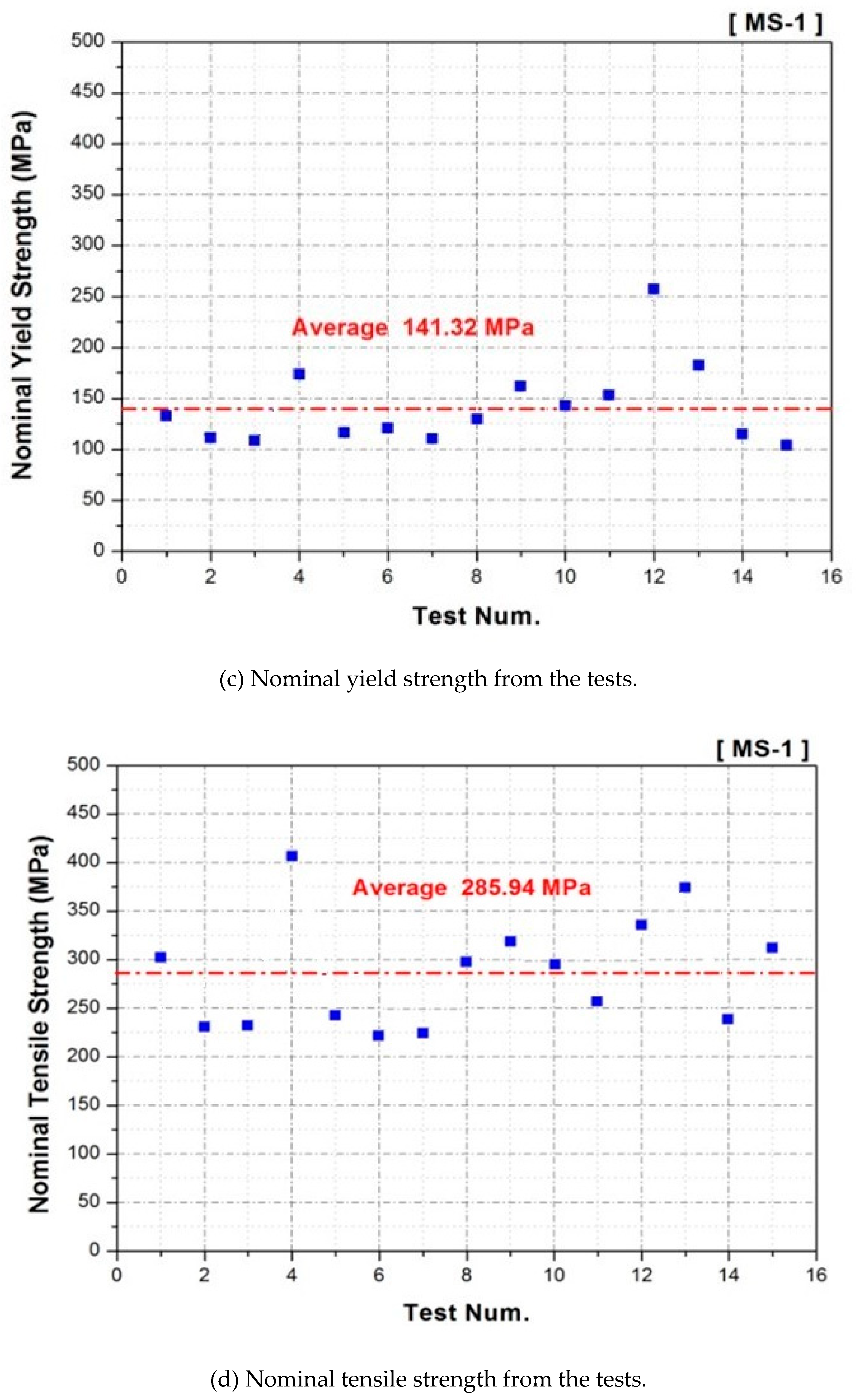
| Costal Cartilage | 19.92 MPa | 1203 | 0.4 | 141.32 | 285.94 |
| Direction | Value(N/mm) |
|---|---|
| Tensile direction | 486 |
| Compressive direction | 3300 |
© 2020 by the author. Licensee MDPI, Basel, Switzerland. This article is an open access article distributed under the terms and conditions of the Creative Commons Attribution (CC BY) license (http://creativecommons.org/licenses/by/4.0/).
Share and Cite
Kim, E.S. Accident Reconstruction of Damaged Human Body Using MDCT and Computer Numerical Analysis. Appl. Sci. 2020, 10, 3059. https://doi.org/10.3390/app10093059
Kim ES. Accident Reconstruction of Damaged Human Body Using MDCT and Computer Numerical Analysis. Applied Sciences. 2020; 10(9):3059. https://doi.org/10.3390/app10093059
Chicago/Turabian StyleKim, Eui Soo. 2020. "Accident Reconstruction of Damaged Human Body Using MDCT and Computer Numerical Analysis" Applied Sciences 10, no. 9: 3059. https://doi.org/10.3390/app10093059
APA StyleKim, E. S. (2020). Accident Reconstruction of Damaged Human Body Using MDCT and Computer Numerical Analysis. Applied Sciences, 10(9), 3059. https://doi.org/10.3390/app10093059