Article

Power Capacity Optimization in a Photovoltaics-Based Microgrid Using the Improved Artificial Bee Colony Algorithm

1
State Key Laboratory of Reliability and Intelligence of Electrical Equipment, Hebei University of Technology, Tianjin 300130, China
2
Department of Electronic Engineering, National Chin-Yi University of Technology, Taichung 41170, Taiwan
3
School of Civil Engineering, Lanzhou University of Technology, Lanzhou 730050, China
*
Author to whom correspondence should be addressed.
Appl. Sci. 2020, 10(9), 2990; https://doi.org/10.3390/app10092990
Submission received: 11 March 2020 / Revised: 21 April 2020 / Accepted: 23 April 2020 / Published: 25 April 2020
(This article belongs to the Special Issue Applied Optimization in Clean and Renewable Energy: New Trends)

Abstract

:
Although the combined cooling, heating and power (CCHP) microgrid is feasible for achieving a high energy utilization efficiency, the fluctuation of energy sources, such as a photovoltaic system and multiple loads, may affect the safety, economics and stability in CCHP microgrid operation. For this reason, this paper establishes a mathematical model using a multi-objective optimization mechanism for resolving the influence of economy and energy allocation in the mixed photovoltaic type CCHP microgrid. It is based on analytic hierarchy process (AHP) to determine the individual weight of objective function optimization for the multi-objective power capacity allocation. The improved artificial bee colony (IABC) based on the whale search and dynamic selection probability can achieve an optimization solution, reaching a stable operation state and reasonable capacity configuration in the microgrid system. The performance results confirm that the proposed algorithm is superior to others in both convergence speed and accuracyfor the capacity allocation of the CCHP microgrid.
Keywords:
CCHP; AHP; whale search; IABC

1. Introduction

With the environmental aggravation and energy shortage in the world, distributed generation (DG) using renewable energy has been attracting extensive attention in recent years. However, renewable energy has inherent volatility and intermittency. To resolve this problem, the microgrid system combined with large power grids has been developed to be faster than before. For example, a combined cooling, heating and power (CCHP) type microgrid allows users to determine the system structure and power capacity [1]. Therefore, it is of great significance to optimize the capacity of the CCHP microgrid to be more economical, safe and reliable, and have more environmental friendliness and energy conservation.
A CCHP microgrid operation optimization model for wind-generated energy was established by taking the minimum total operating cost in the objective function [2]. However, it requires a complicated calculation with a long computation time due to the mixed integer programming process. In [3], a CCHP mathematical model was developed by adopting the improved particle swarm optimization algorithm. The objective of minimizing the operation cost was achieved under the computational simulation. Although the above two methods satisfied the economic optimum, both environmental and energy issues were not fully taken account of. In [4], a hybrid microgrid model of a landscape system and CCHP was reported to construct evaluation indexes from the three aspects of energy, economy and environment. In [5], a planning model with comprehensive consideration of carbon dioxide emission and total system cost was established using theoptimization software (CPLEX). The capacity configuration was simulated using Energy Plus software.The above two schemes improved the capacity allocation optimization model, but there was no sufficient clarification on the weight of the multi-objective function.
Prior studies usingthe optimization methods have made some progress in this field. For instance, [6] proposed a hybrid solution to meet the residential energy demand, which was composed of micro-CHP units and solar power units. Alternatively, [7] evaluated the performance of several designs ofhybrid CHP systems composed of solar thermal collectors, photovoltaic panels and natural gas internal combustion engines. Compared with the traditional mathematical methods, meta-heuristic algorithms had the advantages of fast solving speed and high accuracy in dealing with the highly coupled problems [8,9].
The genetic algorithm (GA) was proposed to optimize the capacity of configuration for the energy consumption, operation cost, and pollutant emission index in the CCHP system [10]. Ref. [11] established a microgrid system mixed with a photovoltaic power generation system and CCHP. It wasa multi-objective function based on energy, environmental protection and economy. The particle swarm optimization (PSO) algorithm was adopted to minimize the value of the objective function. However, typical GA, PSO, DE and other algorithms may be easily trapped intoa local convergenceand get unsatisfactory results. For this reason, a new CCHP microgrid model based on a multi-objective optimization and hybrid multi-objective intelligent algorithm(C-NSGA-II) wasproposed [12]. It was focused on environmental benefit, energy saving rate and security. In [13], the chaos-mutation-whale optimization algorithm achieved an optimization solution of a CCHP system in a shorter number of iterations. On the other hand, ahybrid algorithm that combined DE and PSO algorithms was proposed to optimize the CCHP systems [14].
The artificialbee colony (ABC)algorithm is often used to optimize the weighting factors of a multi-objective function [15]. Therefore, a new optimizationapproach based on the ABC algorithm was developed to determine the optimal DG-unit’s size, power factor, and location for minimizing the total system real power loss [16]. In [17], a multi-period ABC optimization algorithm wasproposed foreconomic dispatch, considering generation, storage and responsiveload offers. However, the convergence rate may decrease when it is applied to a multi-dimensional multi-objective function model.
To sum up, the optimization of capacity allocation in the CCHP microgrid still requires further improvement as follows: (1) A new energy power generation hybrid system should be given more attention because of the greatchallenge of the recent energy crisis and environmental problems. (2) The multi-objective function constructed by taking the economic, energy and environmental factors should find an appropriate weight for the capacity allocation. (3) PSO, GA, DE and other typical algorithms were widely applied to find the optimization solutionfor the power capacity allocation, but they may be trapped into the local minima solution, which will affect the optimization performance.
In this paper, amathematical model that considers the hybrid microgrid based on the photovoltaic and CCHP systemis built. Amulti-objective function is constructed by taking the economy, energy saving and environmental protection into account. The weight of the multi-objective function is determined by the analytic hierarchy process. Under the four scheduling strategies, the improved artificial beecolony (IABC) algorithm is developed to achieve the optimization solution for the power capacity allocation. In addition, another three classical algorithms are compared to verify the superiority of IABC in terms of convergence accuracy and speed.

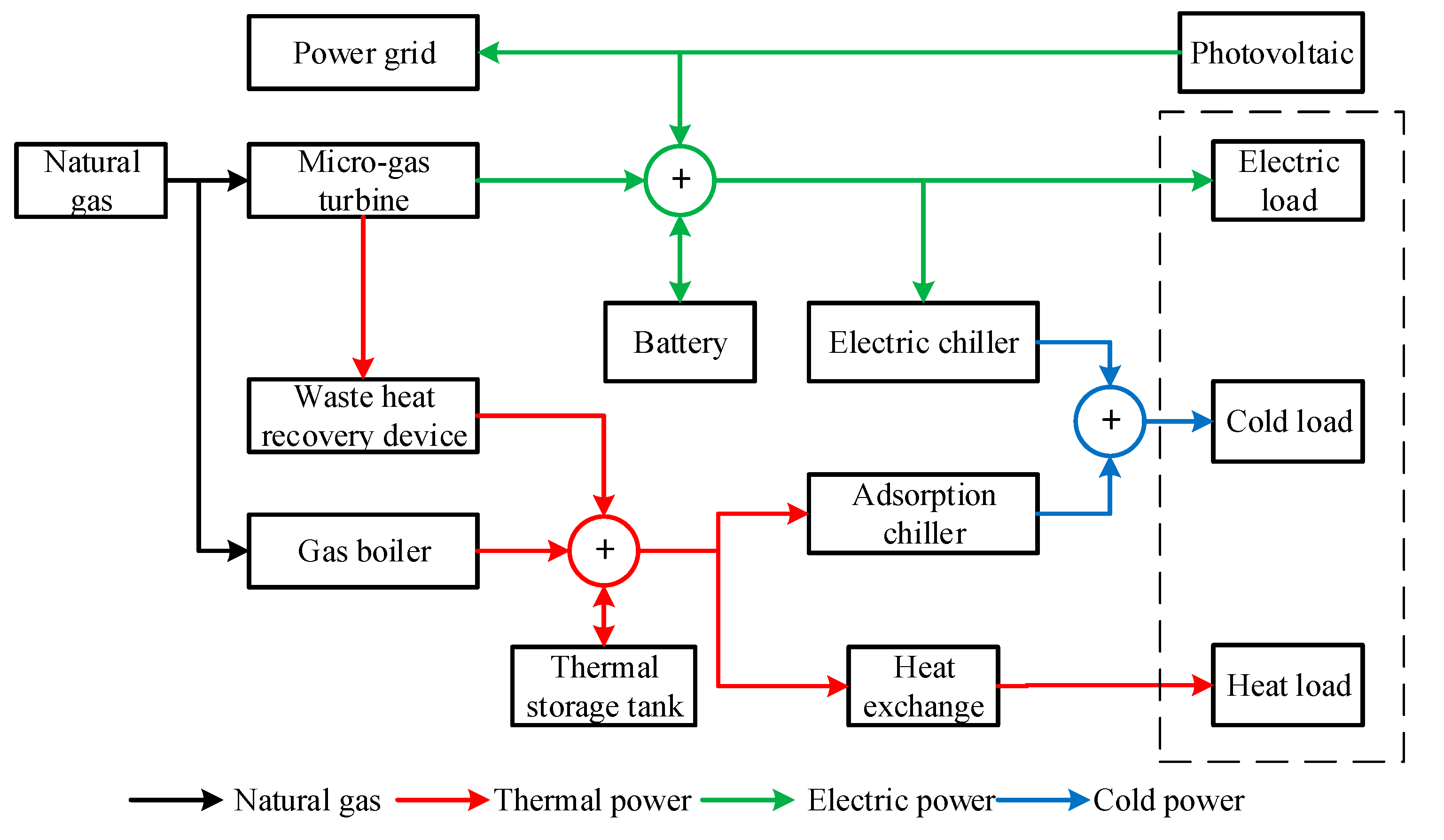
2. CCHP Microgrid System

The structure of the CCHP microgrid system is shown in Figure 1. Itcontains cold, heat and electric loads [18]. The electric power is mainly supplied by the micro-gas turbine and photovoltaic power generation system. The heat power is supplied by the waste recovered heat from both the micro-gas turbineand gas boiler, which originally consume natural gas. The coldpower is mainly supplied by the electric chiller and the adsorption chiller, which consumes the electric energy and converts the heat energy into the cold energy, respectively.
The mathematic model of the photovoltaic (PV) generator is described as
E p v = E p v N G G S T C [ 1 + k ( T c T S T C ) ]
where E p v N is the maximum output power of photovoltaic cells under standard test conditions (GSTC = 1000 W/m2, TSTC = 25 °C). G is the actual light intensity; k is the power temperature coefficient of the photovoltaic cell. Tc is the surface temperature of the photovoltaic cell, which is close to the actual ambient temperature.
The mathematic model of the micro-gas turbine (MT) is described as
E m t = F m t η m t
where Emt is the power generated by MT. Fmt is the fuel consumed by MT. ηmt is the production efficiency of MT.
The mathematic model of the battery is described as
E c ( t ) = E S T C [ 1 + δ B ( T b ( t ) T S T C ) ]
{ c h a r g e : E b ( t ) = ( 1 η b ) E b ( t 1 ) + P c ( t ) Δ t η c d i s c h a r g e : E b ( t ) = ( 1 η b ) E b ( t 1 ) P d ( t ) Δ t η d
where Ec(t) represents the actual capacity of the battery at time t. ESTC represents the capacity of the battery under standard test conditions. δB is the capacity temperature coefficient. Tb(t) is the surface temperature of the battery at time t, approximately equal to the ambient temperature. TSTC is the temperature under standard test conditions [19]. Eb(t) represents the remaining charge of the battery at time t. Eb (t − 1) represents the remaining charge of the battery at time (t − 1). ηb is the self-discharge rate of the battery. Pc(t) and Pd(t) are the charge and discharge power. ηc and ηd are the charging and discharging efficiency of the battery, respectively [20]. Δt is the time interval.
The mathematic model ofthe thermal storage tank (TST) is described as
H t s t ( t + 1 ) = H t s t ( t ) ( 1 α t s t ) + ( η t s t , c h r H t s t , c h r ( t ) H t s t , d i s ( t ) η t s t , d i s ) Δ t
where Htst,chr and Htst,dis are the heat storage and heat release power in the thermal storage tank, respectively. Htst(t) is the heat energy stored in the thermal storage tank at time t. αtst is the self-loss coefficient. ηtst,chr and ηtst,dis are the heat storage efficiency and heat release efficiencyof TST, respectively [21].
The mathematic model of the gas boiler (GB) is described as
H g b = F g b η g b
where Hgb is the thermal power generated from the GB. Fgb is the fuel consumption of the boiler. ηgb is the efficiency of the boiler.
The waste heat recovery device (WHRD) recycles the heat from micro-gas turbines. The mathematic model of WHRD is described as
H r e = F m t η r e ( 1 η m t )
where Hre is the heat recovered by WHRD. ηre is the waste heat recovery efficiency of heat energy.
The mathematic model of heat exchange(HE) deviceis described as
H ( t ) = H h e ( t ) η h e
where H(t) is the output power of the HE deviceat time t; Hhe(t) is the input power of the heat exchangerat time t; ηhe is the efficiency ofthe HE device.
The mathematic model of the electric chiller (EC) is described as
Q e c ( t ) = E e c ( t ) C O P e c
where Eec(t) is the input power of ECat time t; Qec(t) is theoutput power of ECat time t; COPec is the refrigeration coefficient of EC.
The mathematic model of the adsorption chiller (AC) is described as
Q a c ( t ) = H a c ( t ) C O P a c
where Hac(t) is the input power of ACat time t; Qac(t) is theoutput power of ACat time t; COPac is the refrigeration coefficient of AC.

3. Capacity Optimization Model

3.1. Selection of Decision Variables

Modern CCHP microgrid systems contain a variety of loads [22]. For this reason, every load and power supply source can be regarded as a variable to be optimized for the power capacity allocation. Among variables, the capacity of a photovoltaic power generation system can determine the penetration strength of green energy in the CCHP microgrid [23]. In addition, the capacity of the micro-gas turbine can greatly affect the supply of electric, heat and cold loadin the CCHP microgrid [24]. The upper limit of the exchange power in the grid directly determines the upper limit of the power that the microgrid buys or sells from/to the grid. Therefore, this variable should not be set too large. Otherwise, it may cause an unnecessary impact on the grid. Moreover, the energy storage system and thermal storage tank are important devices for stabilizing power fluctuations. If their capacity configuration is too low, the stored energy is not sufficientto meet the demand of the load. If the capacity allocation is too large, it will inevitably cause unnecessary waste. As the main source of heat, the capacity configuration of the gas boiler must be reasonably distributed to ensure the reliable power supply of the microgrid system.
As above, this study selects six device capacities as system decision variables.
X = [ N p v , N m t , N g r i d , N b , N t s t , N g b ]
where Npv, Nmt, Ngrid, Nb, Ntst and Ngb are the installed capacity of PV, MT, interactive with power grid (electricity purchase and sale from/to power grid), battery, TST and GB, respectively.

3.2. Evaluation Mechanism

3.2.1. Economic Evaluation

Theannual total cost (ATC) includes the initial investment cost, interaction cost with power grid, and fuel cost. The smaller ATC is, the better the economy achieves.
A T C = i = 1 K C i N i + t = 1 T [ E g r i d , i n ( t ) C e ( t ) E g r i d , o u t ( t ) C e ( t ) + F m t ( t ) C f ( t ) + F g b ( t ) C f ( t ) ]
where Ci is the cost of the i-th equipment; Ni is the installation capacity of the i-th equipment; Egrid,in(t) is the amount of electricity purchased from the grid during system operation; Egrid,out(t) is the amount of electricity sold to the grid during the system operation [25]; Ce(t) is the time-of-use electricity price; Cf(t) is the time-sharing gas price.

3.2.2. Energy-Saving Evaluation

TEC defined in Equation (13) represents the total energy consumption of the entire CCHP hybrid system [26]. The smaller the energy consumed, the better the energy conservation thatthe system achieves.
T E C = F m t + F g b + λ t = 1 T [ E v a c a n c y ( t ) + E w a s t e ( t ) + H v a c a n c y ( t ) + H w a s t e ( t ) ]
where Fmt is the fuel consumptionof the micro-gas turbine. Fgb is the fuel consumption of the gas boiler. Evacancy and Ewaste represent the power shortage and power waste; Hvacancy and Hwaste represent the heat shortage and heat waste [13]; λ is the punish coefficient.

3.2.3. Environmental Evaluation

The pollutants emitted from the CCHP system are mixed, mainly including CO2, CO, NOX and PM, among which CO2 accounts for more than 99.5%. Therefore, carbon dioxide emission (CDE) is adopted as the environmental evaluation index [27].
C D E = E g r i d μ e + ( F m t + F g b ) μ f
where CDE is the emission of CO2 (kg); μe (g/kWh) is the CO2 emission coefficient corresponding to the purchased electricity; μf (g/kWh) is the CO2 emission coefficient corresponding to the combustion of natural gas.

3.3. Establishment of Multi-Objective Optimization Model

This study develops a multi-objective function F(X) based on the combination of economy, energy saving and environmental protection, which gives a certain weight to each evaluation index to reflect its contribution to the whole [28].
F ( X ) = m i n [ ω 1 A T C + ω 2 T E C + ω 3 C D E ]
In this paper, the AHP algorithm is adopted to determine the value of the weight coefficient for the allocation of capacity of the CCHP system. The procedure is described as follows.
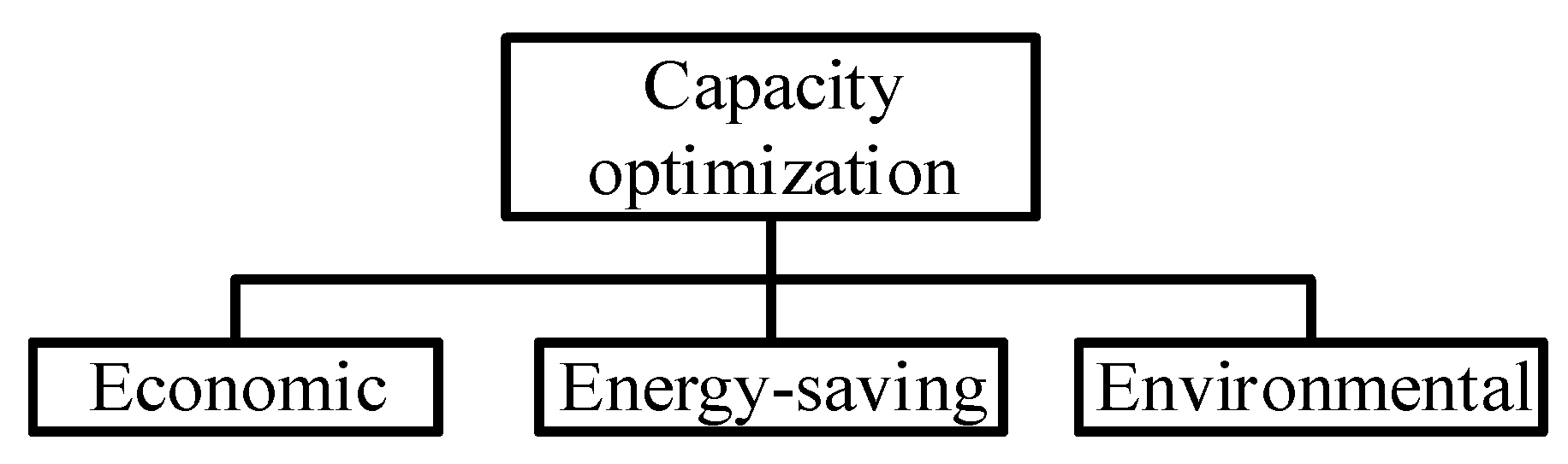
  • Establish the hierarchical analysis structure of capacity optimization. According to the composition of the multi-objective function, the target is the capacity optimization, where the criterion layer includes economy, energy saving and environmental protection, as shown in Figure 2.
  • Construct judgment matrix. A(aij)n×n is the judgment matrix. aij is the comparison weight of relative importance obtained by pairwise comparison of standard layer indicators. Twenty experts were consulted to complete the questionnaire [29]. Experts rate the relative importance (between two factors) of the criterion layer. The scale of relative importance is 1–9 [30]. Calculate the arithmetic mean of the comparison weight column of relative importance between each two factors, and then round to get aij. Finally, A(aij)n×n is obtained.
    A = [ 1 3 5 1 / 3 1 3 1 / 5 1 / 3 1 ]
  • Weight sorting. The weight ordering refers to the ordering of the importance of each element in the standard layer for the target layer. First, calculate the element product of each row of the judgment matrix, and then find the n-th square root of the element product of each row to obtain the eigenvector matrix. At last, normalize the sum of the eigenvectors to be 1, and then obtain the weight vector W. The specific steps are expressed as follows.
    { M i = j = 1 n a i j ( i = 1 , 2 , , n ) W i ¯ = M i n W i = W i ¯ / j = 1 n W j ¯
    where Mi is the score of elements in each row of the judgment matrix; W i ¯ is the n-th root of Mi; Wi is the i-th element of the matrix W. The calculated results are: W = [0.637, 0.258, 0.105]T.
  • Conduct theconsistency test for the judgment matrix. Consistency index (CI), Randomconsistency index (RI) and Consistency ratio (CR) are calculated as follows.
    { λ m a x = 1 n i = 1 n ( A W ) i W i C I = ( λ m a x n ) / ( n 1 )
    where λmax is the maximum characteristic root of matrix A. (AW)i is the i-th element of the matrix AW. Substitute the W matrix obtained in step (3) into Equation (18): λmax = 3.038, CI = 0.019. According to the RI value table with a sample size of 100–500 given by Satty, it can be obtained: RI = 0.58. CR = CI/RI = 0.033 < 0.10 [31]. This indicates that the judgment matrix has a satisfactory consistency, and its normalized feature vector can be used as the weight vector. The final result from the above steps is obtained as ω 1 = 0.637 ,   ω 2 = 0.258 ,   ω 3 = 0.105 .

3.4. Constraints

The constraints mainly include the capacity constraints ofequipment, electricity balance, heating balance, and cooling balance.Decision parameters and their range of variations are listed in Table 1.
The heat storage tanks and batteries have some constraints in the specific operation.
{ H t s t , c h r m i n H t s t , c h r ( t ) H t s t , c h r m a x H t s t , d i s m i n H t s t , d i s ( t ) H t s t , d i s m a x S O C m i n S O C ( t ) S O C m a x P b , i n ( t ) P b , i n m a x , P b , o u t ( t ) P b , o u t m a x
where Htst,chr(t) and Htst,dis(t) are the heat storage and heat release power in the thermal storage tank, respectively; SOC(t) is the charged state of the battery at time t; Pb,in(t) and Pb,out(t) are the charging and dischargingpower of the battery, respectively [32].
Theelectrical power balance is as follows:
E p v ( t ) + E m t ( t ) + E g r i d , i n ( t ) + E b , o u t ( t ) = E g r i d , o u t ( t ) + E b , i n ( t ) + E ( t ) + E e c ( t )
where Epv(t) and Emt(t) represent the electric energygenerated from the photovoltaic power generation system and micro-gas turbine at time t, respectively. Egrid,in(t) and Egrid,out(t) represent the electricity purchased and sold from/to the grid at time t, respectively. Eb,in(t) and Eb,out(t) are the charging and discharging power of the battery at time t, respectively. E(t) represents the power load demand at time t. Eec(t) represents the energy consumed by the electric refrigerator at time t.
Theheat power balance is as follows:
H r e ( t ) + H g b ( t ) + H t s t , o u t ( t ) = H t s t , i n ( t ) + H h e ( t ) + H a c ( t )
where Hre(t) is the waste heat recovered by RE at time t. HGB(t) is the heat generated by the gas boiler at time t. Htst,in(t) and Htst,out(t) are the heat energy absorbed and released by the heat storage tank at time t, respectively. Hhe(t) is the heat energy consumed by the heat exchanger at time t. Hac(t) is the heat energy consumed by the adsorption chiller at time t [28,32].
Thecold power balance is as follows:
Q a c ( t ) + Q e c ( t ) = Q ( t )
where Qac(t) is the cold energy generated by the adsorption chiller at time t; Qec(t) is the cold energy generated by the electric chiller at time t; Q(t) is the cooling load demand at time t.

4. Optimization Method

4.1. Improved Scheduling Strategy

Two improved scheduling strategies based on traditional ones are proposed in this study. The following four scheduling policies are described in detail.

4.1.1. Traditional “Following Electric Load” (FEL) Strategy

The FEL strategy assures that the electrical energy generated by the CCHP system matches the electric load demand at any time. Priority is given to the photovoltaic power generation to meet the demand of the electric load and electric chiller [33,34,35]. If photovoltaic power generation cannot satisfy the demand of the electric load and electric chiller, the gas turbine will be taken as a backup power to fill the demand of the power load. On the contrary, if the generated power from the photovoltaic power generation is greater than the power demand, the excess power is sold to the grid [34].

4.1.2. Traditional “Following Heat Load” (FHL) Strategy

The collection of waste heat from the micro-gas turbine should match the demand of the adsorption chiller and heat load of exchanger conversion at any moment. If it is not satisfactory, the gas boiler is used as a backup heat source to fill gaps [35]. On the contrary, if it exceeds the demand of the adsorption chiller and heat load, the extra heat energy is stored in the heat storage tank [36,37].

4.1.3. Improved “Following Electric Load” (IFEL) Strategy

The synergy power generated from the micro-gas turbine and photovoltaic power generation system should match the demand of the electricity load and refrigerating machine at any moment. If the generated power is more than the demand, the excess power can be used to charge the battery storage system. If it is insufficient to support the demand, the energy can be supplied from the battery storage system or an external grid.

4.1.4. Improved “Following Heat Load” (IFHL) Strategy

The heat energy generated from the micro-gas turbine and gas boiler should match the load demand by the adsorption refrigerating machine and heat exchanger for conversion of heat load at any moment. If the heat energy produced is more than the load demand at any moment, excess heat energy will be stored in the heat storage tank. However, it will cause excess heat energy waste once it is beyond the capacity of the heat storage tank. On the contrary, if the generated heat is insufficient, the heat storage tank is used to resupply. The flowchart of four strategies is shown in Figure 3.

4.1.5. Improved Artificial Bee Colony Algorithm

In the typical ABC algorithm, there are three types of individuals: hired bees, observer bees and detection bees [38]. Each hired bee corresponds to a defined honey source (solution vector), and the area of the honey source is searched during the iteration. According to the abundance of the nectar source (the size of the adaptive value), a roulette wheel is used to select observer bees to collect honey (search for new nectar source). If the honey sourcesare not improved after several updates, the honey source are abandoned and the hired beesare turned into detection bees to search for the new honey source randomly [39].
(a) Population Initialization
Random numbers matching the predefined range are randomly generated on each element of the honey source position matrix to fill the honey source position matrix. The expression of the population initialization is expressed as follows.
x i , d = l d + l h s d e s i g n ( 0 , 1 ) ( u d l d )
where ld and ud are the lower and upper bounds of the d-dimensional search space, respectively; lhsdesign(0,1) represents a random number of (0,1) generated by Latin hypercube sampling. Compared with the traditional rand distribution, lhsdesign can make every individual in each dimension of the initial population within the interval of uniform distribution, ensuring that the initial population can contain locally optimal individuals and ensuring the convergence of the algorithm.
(b) Hired Bee Stage of the Hybrid Whale Search Strategy
The hired bees are responsible for finding suitable honey sources within the designated search area. Then, the information of the source is saved. The formula for searching the honey source is shown as follows.
u i , d = x i , d + r ( x i , d x k , d )
where ui,d represents the location of the new nectar source. xi,d is the d-dimension values of the ith nectar source. xk,d is the d-dimensional value of a randomly selected nectar source among N nectar sources, and ki. r represents the random number within the interval [−1,1].
In the typical ABC, both hirer and observer bees use Equation (24) to conduct one-dimensional operations, which has a strong global search ability but low search efficiency. Thewhale optimization algorithm (WOA) is a new algorithm to simulate the hunting behavior of humpback whales in the ocean [40]. The contraction enveloping mechanism is simulated by Equation (25). A spiral equation is established between the position of whale and prey to simulate the spiral motion of humpback whales as shown in Equation (26). In order to simulate the simultaneous occurrence of both movements in the humpback whale, it is assumed that there is a 50% probability that a choice can be made between the narrowing of the enveloping mechanism and the spiral model, as shown in Equation (27).
This paper combines the WOA to improve the search mode of hired bees. The behavior of bees searching for honey is modeled based on that of humpback whales searching for prey.
{ A = 2 a r a C = 2 r D = | C x d * x i , d | u i , d = x i , d A D
u i , d = D e b l cos ( 2 π l ) + x i , d
u i , d = { x i , d A D D e b l cos ( 2 π l ) + x i , d p < 0.5 o t h e r w i s e
where a is the iteration number that decreases linearly from 2 to 0; r is a random number within the range [0,1]; x d * is the d-dimension value of the current optimal nectar source; b is a constant; l is the random number within the range of [−1,1]; p is a random number within the range [0,1].
When the new honey source is obtained, the fitness values of new and old honey sources are calculated by Equation (28).
f i t i = { 1 / ( 1 + f i ) 1 + | f i | f i > 0 o t h e r w i s e
where fiti represents the fitness value of the ith nectar source; fi represents the value of the objective function of the ith solution. The greedy algorithm (29) is used to compare the fitnessvalues of new and old honey sources and update the honey sources.
x i = { u i x i f i t ( x i ) < f i t ( u i ) o t h e r w i s e
(c) The Observer Bee Stage of the Dynamic Adjustment of Pi
Pi is the selection probability of each honey source in the typical ABC algorithm. After the hired bees update the honey source, they fly back to the information exchange area to share the honey source.The observer bees calculated the Pi according to the honey source information shared by the hired bees.The calculated Pi is used to perform roulette to select the honey source. According to Equation (24), the observer bees update the nectar source near the selected nectar source and determine the nectar amount of the new nectar source.If the fit of the new solution is better than the previous one, the observer bee will remember the new solution instead of the old one.
P i = f i t i / i = 1 N f i t i
P i d = [ ( P m a x P 0 ) t 2 t m a x 2 + P 0 ] P i
The Pi formula of the typical ABC algorithm is shown in Equation (30). The higher the fitness value of a honey source, the greater the probability that a better honey source will be selected. However, in the later stage of the algorithm, there are already many dominant individuals in the population. If the population is selected with fixed Pi, the dominant individuals may be destroyed and the convergence rate will be slowed down. In this paper, Pi is improved into a dynamic function with the number of iterations as the independent variable, as shown in Equation (31), where Pid is the selection probability of each honey source in the IABC algorithm. P0 and Pmax are the minimum and maximum selection probabilities, respectively. In the initial stage of the algorithm, Pid is close to Pi. With the progress of the algorithm, Pid increases slightly, and in the later stage, dominant individuals can be better highlighted. The convergence rate of the algorithm is thus accelerated.
(d) Detection Bee Stage
When the mining times of the honey source reaches the limit, the fitness value of a certain honey source remains unchanged. This means that the honey source mining is trapped into a local optimum. Then, the honey source should be abandoned, and the hired bee changes to the detection bee. A new honey source location is generated according to Equation (23).
The specific steps of the improved artificial bee colony algorithm are as follows:
Step 1
Initialize population: initializing all parameters, e.g., the total number of bees NP, the maximum number of iterations tmax, the control parameter limit, lower (ld) and upper (ud) bounds of the search space; and randomly generating initial solution {xi i = 1, 2..., NP};
Step 2
Calculate the adaptive value of each bee in the population;
Step 3
Set the parameters of the whale search strategy: a, b, l, p. The hired bee generates a new solution ui,d, according to Equation (27), and calculate the fitness value;
Step 4
The hired bee selects the nectar source according to the greedy strategy;
Step 5
Calculate the selection probability Pi according to Equations (30) and (31);
Step 6
The observer bees select the honey source according to the probability Pi, and generate a new one near the honey source according to Equation (24). Meanwhile, the fitness value of the new honey source is calculated. Finally, the source of honey is selected using the greedy algorithm;
Step 7
Determine whether detection bees exist. If so, randomly generate a honey source to replace them according to Equation (23);
Step 8
Check whether the end condition is satisfied. If not, repeat Steps 3–7, or output the optimal solution.
There are six decision variables, e.g., Npv, Nmt, Ngrid, Nb, Ntst and Ngb, regarded as the locations of the nectar sources in the CCHP microgrid capacity optimization configuration. The multi-objective function value established is regarded as the quantity of nectar. The IABC algorithm process is to find a set of optimal solutions to minimize the value of the objective function. The optimization method based onthe IABC algorithm is shown in Figure 4.

5. Analysis of Model Performance

In this study, large hotels in 16 commercial reference buildingspublished by the U.S. Department of Energy (DOE) were selected as the research carrier to test the operation state of the microgrid system [41,42]. The prices of the various equipment used are shown in Table 2. The cost of each equipment is cited in reference [4]. The electricity price and natural gas price are shown in Table 3. The parameters of the CCHP system are shown in Table 4. The parameter setting of the CCHP system is cited in reference [4,11,12]. The entire experiment was performed using Microsoft Windows 8 operating system and MATLAB R2014a software (MathWorks, Natick, MA, USA) developer, city, country. The computer configuration used Core i5, 3.0 GHz, 8 GB RAM.
According to the cold, heat and electric load curves, as shown in Figure 5, the following characteristics of energy demands can be derived as:
(1)
The electricity load per hour fluctuates greatly at the morning and evening peak periods, where it is generally larger than the cold and hot load;
(2)
The great fluctuation of heat load occurringin the morning and evening during the day is due to the special environment of the selected hotel;
(3)
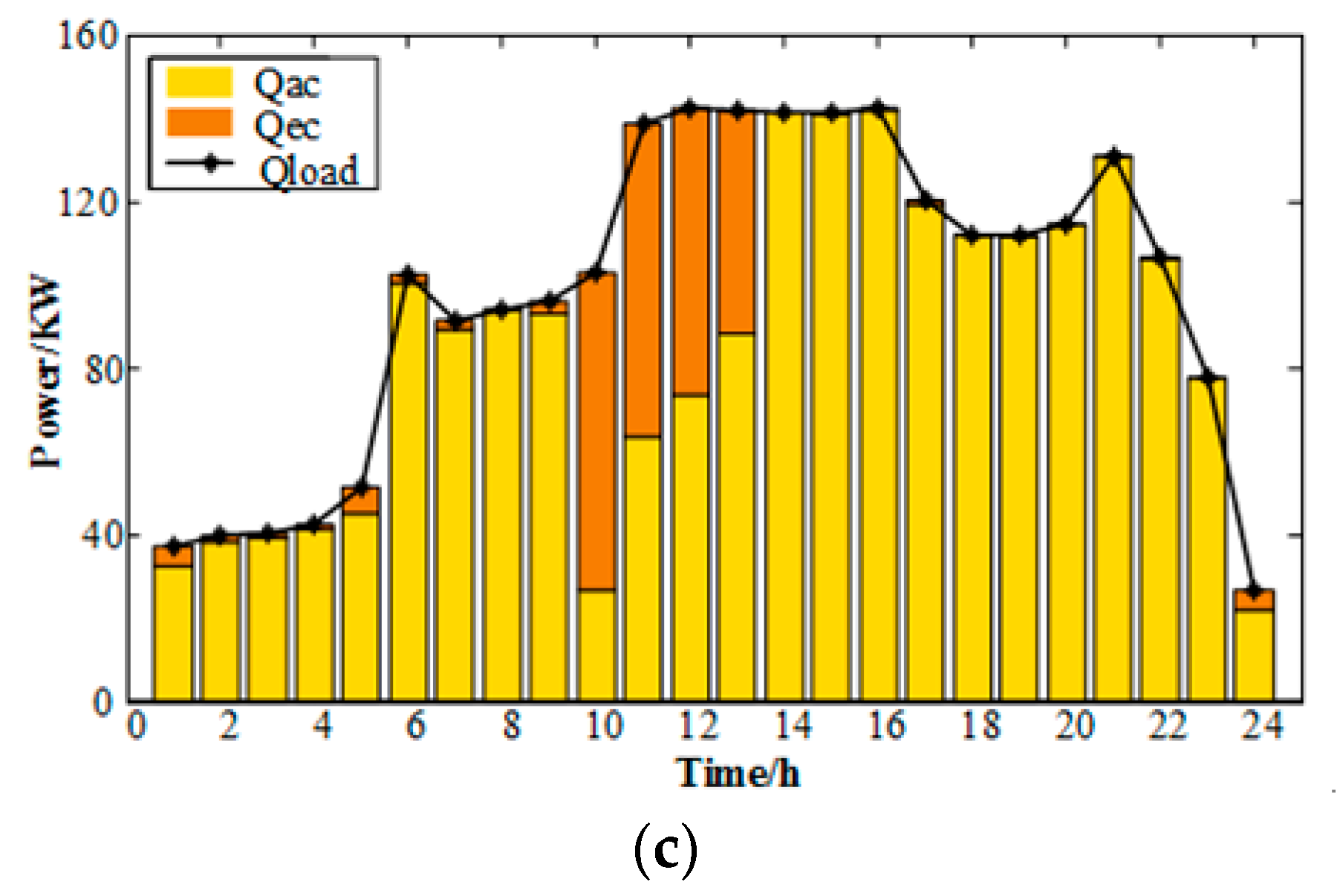
The daily cooling load demand is stable because of the hot local climate.

5.1. Analysis of Operation Conditions

5.1.1. Analysis of Operation Using FEL Strategy

From Figure 6a, under the FEL strategy, it was found that the electrical power mainly comes from the micro-gas turbine and power grid. The micro-gas turbine power supply is more stable. However, the power grid provides more electricity than the micro-gas turbine power. On the other hand, the micro-gas turbine provides more power than the photovoltaic system. The grid power purchase is more economic than the micro-gas turbine and photovoltaic power system. From 7:00 to 15:00, when the sunlight is relatively sufficient, the photovoltaic power generation system participates in the power supply task. Nevertheless, its contribution is very small due to the economic cost. From Figure 6b, the heat power is mainly supplied by the micro-gas turbine and the gas boiler. However, the output of the gas boiler varies with the fluctuation of the load. In contrast, the output of the micro-gas turbine is relatively stable. Moreover, the system adopts the operation strategy of FEL. From Figure 6c, the first priority is to meet the demand of electric load. Subsequently, redundant electric energy is produced to cool. Therefore, the AC bears more cold load than the EC. Note that the Eload increases substantially at 6 o’clock. Under the FEL strategy, the electric balance is satisfied, and there is no excess electrical energy to provide EC to generate cold power at this stage. To maintain the cold power required by the users, the Qac therefore increases abruptly.

5.1.2. Analysis of Operation Using the FHL Strategy

As can be seen from Figure 7a, under the FHL strategy, electric energy is mainly supplied by the micro-gas turbine and power grid, but a little fluctuation appears in the micro-gas turbine power supply. In terms of power supply economic benefit, it is the same result as that under the FEL strategy. From 7:00 to 16:00, the photovoltaic power generation system participates in the power supply task, but its contribution is limited due to the restriction of economic cost. From Figure 7b, the heat powers are mainly supplied by the micro-gas turbine and the gas boiler. Their output varies with the fluctuation of load. From Figure 7c, the electric chiller can bear more cold load than the adsorption chiller. The system adopts the strategy of FTL, and it ensures itmeets the demand of the heat load. Simultaneously, redundant heat energy is generated for refrigeration. Note that the Hload goes down considerably at 11 o’clock. At this time, the Eload is stable, and Emt thus remains stable. In addition, MT’s waste heat recovery device still produces a stable Hre. Under the FHL strategy, the heat balance is preferentially satisfied, and a large amount of heat energy can only supply AC to generate cold power. This results in theQac increasing suddenly.

5.1.3. Analysis of Operation Using the IFEL Strategy

As can be seen from Figure 8a, under the IFEL strategy, the power is mainly supplied by the photovoltaic, micro-gas turbine and power grid. During 0:00~2:00, the discharge of the battery supplements a small part of the electric load. From 7:00 to 16:00, the sunlight is relatively sufficient so that the photovoltaic power generation can produce more electric power. The generated power ismainly concentrated on the daytime, reducing the electricity purchase cost from the power grid. Obviously, it alleviates some of the electrical pressure from system. From Figure 8b, the heat power is mainly supplied by the micro-gas turbine. The output of waste heat recovery from the gas turbine varies with the fluctuation of load. The excess heat power is used for the AC cooling. From Figure 8c, the adsorption chiller bears more cold load than the electric chiller. The system adopts the IFEL strategy so that it initially ensures that it meets the demand of the electric load. Incidentally, redundant electric energy is generated for refrigeration.

5.1.4. Analysis of Operation Using the IFHL Strategy

As can be seen from Figure 9a, under the IFHL strategy, the power is mainly supplied by the photovoltaic, micro-gas turbine, power grid and battery. During 0:00~2:00 and 10:00~14:00, the battery, usinga charging and discharging process, maintains the electrical power balance of the CCHP system. From 7:00 to 16:00, when the sunlight is sufficient, the photovoltaic power generation can produce a relatively high electric power outputduring theday, reducing the electricity purchase from the power grid. From Figure 9b, the heat power is mainly supplied by the micro-gas turbine and heat storage tank. The output power from the micro-gas turbine is relatively stable. In Figure 9c, the EC bears more cold load than the AC. When the system adopts the strategy of IFHL, it ensuresitmeets the demand of heat load and then generates redundant heat energy for refrigeration.

5.2. Comparison of Strategies

Under four different scheduling strategies, the proposed IABC algorithm was used to solve the multi-objective optimization model, and the scheduling results of the CCHP system are shown in Table 5. As can be seen from Table 5, under the two scheduling strategies of FEL and FHL, the capacity allocation of photovoltaic power generation (PV) is less, while the capacity allocation of photovoltaic power generation (PV) under the two scheduling strategies of IFEL and IFHLis greater. Therefore, the ATC of these two strategies is larger, while the TEC and CDE are smaller. Under the two scheduling strategies of FEL and IFEL, the capacity configuration of ECis less than that of the latter two strategies, while the capacity configuration of AC is more than that of the latter two strategies due to firstly satisfying the demand of the system electrical load. Under the two scheduling strategies of IFEL and IFHL, a battery is usedto maintain the stable electric load, and a heat storage tank is used to maintain the stable thermal load, alleviating the instability of photovoltaic power generation. In general, the value of the target function F(X) using FHLis the smallest, indicating the best performance.

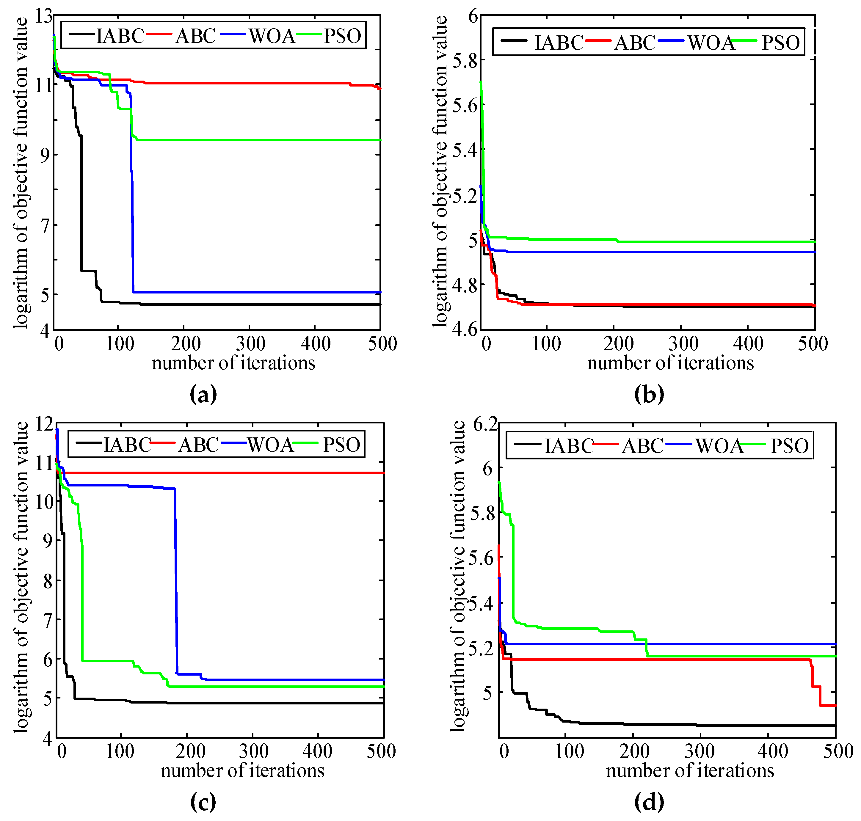
5.3. Comparison of Algorithms

The IABC algorithm, WOA algorithm, ABC algorithm and PSO algorithmare set up to evaluate under the same conditions, i.e., the number of iterations = 500, population number = 32, using different strategies. The objective function values usingfour strategies are concluded in Table 6. Based on the log value of the objective function, thecorresponding convergence curves are shown in Figure 10.
As can be seen from Table 6, under the FEL strategy, the objective function value of IABC is 2.73% lower than that of WOA, 9.52% lower than that of ABC, and 5.67% lower than that of PSO.Under the FTL strategy, the objective function value of IABC decreased by 7.61% compared with WOA, 0.28% lower than the objective function value of the ABC algorithm, and 9.37% lower than the objective function value of PSO.Under the IFEL strategy, the objective function value of IABC is 1.54% lower than that of WOA, 14.98% lower than the objective function value of the ABC algorithm, and 0.73% lower than the objective function value of PSO.Under the IFHL strategy, the objective function value of IABC was 9.27% lower than that of WOA, 2.27% lower than that of the ABC algorithm, and 8.74% lower than that of PSO.In summary, compared with the three algorithms, the objective function value of IABC is the lowest under the four strategies, which can reflect the advantage of IABC in the optimization ability.
In Figure 10a, both the optimization ability and convergence speed of IABC are better than the other three algorithms. In Figure 10b, the convergence results of WOA and PSO are obviously worse than the other two algorithms. On the other hand, the convergence speed of IABC and ABC are comparable. However, the optimization results of IABC are slightly better than ABC. It can be seen from Figure 10c that IABC has the fastest convergence speed and the best optimization outcome. In Figure 10d, the convergence of WOA and PSO is fast, but they get into a local solution. The optimization result of IABC is the best, and its convergence speed is faster than ABC. In conclusion, IABC presents better performance than the other three algorithms in either convergence accuracy or speed.

6. Conclusions

This paper studies the hybrid of photovoltaic power generation and CCHP microgrid systems. The proposed IABC algorithm can achieve the optimal configuration in the capacity allocation of the CCHP microgrid. Major contributions are summarized as follows:
(1)
The capacity optimization modelcomprehensively considers the influence of economy, energy and environment. In addition, the AHP algorithmintegrated with the proposed modelcan find the appropriate weight values of a multi-objective function successfully.
(2)
From the performance analysis of four scheduling strategies using FEL, FHL, IFEL and IFHL, FEL and FHL were found to be more economical but hadless energy-saving and environmental benefits. Contrastively, IFEL and IFHL are less economical but have more energy-savingand environmental benefits instead. Among them, the distributed power supply under the FHL strategy achieves a more stable operation.
(3)
Among the IABC, ABC, WOAand PSO algorithms, under four scheduling strategies, the IABC algorithm presents the best performance in both convergence speed and accuracy.

Author Contributions

Methodology, H.Z.; writing, Z.X., review and editing, H.-C.L.; supervision, S.L. All authors have read and agreed to the published version of the manuscript.

Funding

This study was supported by the key project of Tianjin Natural Science Foundation [Project No. 19JCZDJC32100] and the Natural Science Foundation of Hebei Province of China [Project No. E2018202282].

Acknowledgments

Authors are grateful to the funding support from Tianjin Natural Science Foundation and Natural Science Foundation of Hebei Province of China. All authors have read and agreed to the published version of the manuscript.

Conflicts of Interest

The authors declare no conflict of interest.

Nomenclature

Nomenclature
ATCannual total cost
TECtotal energy consumption
CDEcarbon dioxide emission
CCHPcombined cooling, heating and power
FELfollowing electric load
FHLfollowing heat load
IFELimproved following electric load
IFHLimproved following heat load
AHPanalytic hierarchy process
PVphotovoltaic
MTmicro-gas turbine
TSTthermal storage tank
GBgas boiler
WHRDwaste heat recovery device
HEheat exchange
ECelectric chiller
ACadsorption chiller
COPcoefficient of performance
Symbols
Ccost
Ffuel
Ninstallation capacity
Eelectricity power
Hheat power
Qcold power
ηefficiency
μCO2emission coefficient
Subscripts
pvphotovoltaic
mtmicro-gas turbine
gridelectricity grid
bbattery
gbgas boiler
tstthermal storage tank
rewaste heat recovery device
heheat exchange
ininto
outout
ccharge
ddischarge
STCstandard test conditions
acabsorption chiller
ecelectric chiller
ffuel
eelectricity
loadload
chrheat storage
disheat release

References

  1. Luo, Z.; Yang, S.; Xie, N.; Xie, W.; Liu, J.; Agbodjan, Y.S.; Liu, Z. Multi-objective capacity optimization of a distributed energy system considering economy, environment and energy. Energy Convers. Manag. 2019, 200, 112081. [Google Scholar] [CrossRef]
  2. Zhu, X.; Zhan, X.; Liang, H.; Zheng, X.; Qiu, Y.; Lin, J.; Chen, J.; Meng, C.; Zhao, Y. The optimal design and operation strategy of renewable energy-CCHP coupled system applied in five building objects. Renew. Energy 2020, 146, 2700–2715. [Google Scholar] [CrossRef]
  3. Ju, L.; Tan, Z.; Li, H.; Tan, Q.; Yu, X.; Song, X. Multi-objective operation optimization and evaluation model for CCHP and renewable energy based hybrid energy system driven by distributed energy resources in China. Energy 2016, 111, 322–340. [Google Scholar] [CrossRef] [Green Version]
  4. Yang, G.; Zhai, X. Optimization and performance analysis of solar hybrid CCHP systems under different operation strategies. Appl. Therm. Eng. 2018, 133, 327–340. [Google Scholar] [CrossRef]
  5. Guo, L.; Liu, W.; Cai, J.; Hong, B.; Wang, C. A two-stage optimal planning and design method for combined cooling, heat and power microgrid system. Energy Convers. Manag. 2013, 74, 433–445. [Google Scholar] [CrossRef]
  6. Brandoni, C.; Renzi, M. Optimal sizing of hybrid solar micro-CHP systems for the household sector. Appl. Therm. Eng. 2015, 75, 896–907. [Google Scholar] [CrossRef]
  7. Rodriguez, L.R.; Lissen, J.M.S.; Ramos, J.S.; Jara, E.; Ángel, R.; Domínguez, S. Álvarez Analysis of the economic feasibility and reduction of a building’s energy consumption and emissions when integrating hybrid solar thermal/PV/micro-CHP systems. Appl. Energy 2016, 165, 828–838. [Google Scholar] [CrossRef]
  8. Tang, Y.; Liu, Z.; Li, L. Performance Comparison of a Distributed Energy System under Different Control Strategies with a Conventional Energy System. Energies 2019, 12, 4613. [Google Scholar] [CrossRef] [Green Version]
  9. Li, L.-L.; Yang, Y.-F.; Wang, C.-H.; Lin, K.-P. Biogeography-based optimization based on population competition strategy for solving the substation location problem. Expert Syst. Appl. 2018, 97, 290–302. [Google Scholar] [CrossRef]
  10. Wang, J.; Jing, Y.-Y.; Zhang, C.-F. Optimization of capacity and operation for CCHP system by genetic algorithm. Appl. Energy 2010, 87, 1325–1335. [Google Scholar] [CrossRef]
  11. Yang, L.; Guo, H.; Huang, K. Optimal Dispatch for a Combined Cooling, Heating and Power Microgrid Considering Building Virtual Energy Storage. J. Electr. Eng. Technol. 2019, 14, 581–594. [Google Scholar] [CrossRef]
  12. Gu, W.; Tang, Y.; Peng, S.; Wang, D.; Sheng, W.; Liu, K. Optimal configuration and analysis of combined cooling, heating, and power microgrid with thermal storage tank under uncertainty. J. Renew. Sustain. Energy 2015, 7, 13104. [Google Scholar] [CrossRef]
  13. Li, L.-L.; Liu, Y.-W.; Tseng, M.-L.; Lin, G.-Q.; Ali, M.H. Reducing environmental pollution and fuel consumption using optimization algorithm to develop combined cooling heating and power system operation strategies. J. Clean. Prod. 2020, 247, 119082. [Google Scholar] [CrossRef]
  14. Ma, W.; Fang, S.; Liu, G. Hybrid optimization method and seasonal operation strategy for distributed energy system integrating CCHP, photovoltaic and ground source heat pump. Energy 2017, 141, 1439–1455. [Google Scholar] [CrossRef]
  15. Manna, D.; Goswami, S.K. Optimum placement of distributed generation considering economics as well as operational issues. Int. Trans. Electr. Energy Syst. 2020, 30. [Google Scholar] [CrossRef]
  16. Marzband, M.; Azarinejadian, F.; Savaghebi, M.; Guerrero, J.M. An Optimal Energy Management System for Islanded Microgrids Based on Multiperiod Artificial Bee Colony Combined With Markov Chain. IEEE Syst. J. 2015, 11, 1712–1722. [Google Scholar] [CrossRef] [Green Version]
  17. Abu-Mouti, F.S.; El-Hawary, M.E. Optimal Distributed Generation Allocation and Sizing in Distribution Systems via Artificial Bee Colony Algorithm. IEEE Trans. Power Deliv. 2011, 26, 2090–2101. [Google Scholar] [CrossRef]
  18. Li, M.; Mu, H.; Li, N.; Ma, B. Optimal design and operation strategy for integrated evaluation of CCHP (combined cooling heating and power) system. Energy 2016, 99, 202–220. [Google Scholar] [CrossRef]
  19. Liu, H.; Sui, J.; Han, W.; Wang, Z.; Zhang, N. Operation strategy of interconnected combined cooling, heating, and power systems based on exergoeconomic analysis. J. Clean. Prod. 2020, 245, 118822. [Google Scholar] [CrossRef]
  20. Sanaye, S.; Sarrafi, A. Optimization of combined cooling, heating and power generation by a solar system. Renew. Energy 2015, 80, 699–712. [Google Scholar] [CrossRef]
  21. Wang, M.; Wang, J.; Zhao, P.; Dai, Y. Multi-objective optimization of a combined cooling, heating and power system driven by solar energy. Energy Convers. Manag. 2015, 89, 289–297. [Google Scholar] [CrossRef]
  22. Balakheli, M.M.; Chahartaghi, M.; Sheykhi, M.; Hashemian, S.M.; Rafiee, N. Analysis of different arrangements of combined cooling, heating and power systems with internal combustion engine from energy, economic and environmental viewpoints. Energy Convers. Manag. 2020, 203, 112253. [Google Scholar] [CrossRef]
  23. Ahn, H.; Rim, D.; Pavlak, G.S.; Freihaut, J. Uncertainty analysis of energy and economic performances of hybrid solar photovoltaic and combined cooling, heating, and power (CCHP + PV) systems using a Monte-Carlo method. Appl. Energy 2019, 255, 113753. [Google Scholar] [CrossRef]
  24. Ren, F.; Wang, J.; Zhu, S.; Chen, Y. Multi-objective optimization of combined cooling, heating and power system integrated with solar and geothermal energies. Energy Convers. Manag. 2019, 197. [Google Scholar] [CrossRef]
  25. Li, L.; Yang, Y.; Tseng, M.-L.; Wang, C.-H.; Lim, M.K. A novel method to solve sustainable economic power loading dispatch problem. Ind. Manag. Data Syst. 2018, 118, 806–827. [Google Scholar] [CrossRef]
  26. Nami, H.; Anvari-Moghaddam, A. Small-scale CCHP systems for waste heat recovery from cement plants: Thermodynamic, sustainability and economic implications. Energy 2020, 192, 116634. [Google Scholar] [CrossRef]
  27. Di Somma, M.; Graditi, G.; Heydarian-Forushani, E.; Shafie-Khah, M.; Siano, P. Stochastic optimal scheduling of distributed energy resources with renewables considering economic and environmental aspects. Renew. Energy 2018, 116, 272–287. [Google Scholar] [CrossRef]
  28. Herrando, M.; Pantaleo, A.; Wang, K.; Markides, C.N. Solar combined cooling, heating and power systems based on hybrid PVT, PV or solar-thermal collectors for building applications. Renew. Energy 2019, 143, 637–647. [Google Scholar] [CrossRef]
  29. Mano, T.B.; Guillén-Gosálbez, G.; Jiménez, L.; Ravagnani, M.A.D.S.S. Synthesis of heat exchanger networks with economic and environmental assessment using fuzzy-Analytic Hierarchy Process. Chem. Eng. Sci. 2019, 195, 185–200. [Google Scholar] [CrossRef]
  30. Saaty, T. Decision making—The Analytic Hierarchy and Network Processes (AHP/ANP). J. Syst. Sci. Syst. Eng. 2004, 13, 1–35. [Google Scholar] [CrossRef]
  31. Moaleman, A.; Kasaeian, A.; Aramesh, M.; Mahian, O.; Sahota, L.; Tiwari, G.N. Simulation of the performance of a solar concentrating photovoltaic-thermal collector, applied in a combined cooling heating and power generation system. Energy Convers. Manag. 2018, 160, 191–208. [Google Scholar] [CrossRef]
  32. Luo, J.; Chen, H.; Heidari, A.A.; Xu, Y.; Zhang, Q.; Li, C. Multi-strategy boosted mutative whale-inspired optimization approaches. Appl. Math. Model. 2019, 73, 109–123. [Google Scholar] [CrossRef]
  33. Hou, S.; Zhang, F.; Yu, L.; Cao, S.; Zhou, Y.; Wu, Y.; Hou, L. Optimization of a combined cooling, heating and power system using CO2 as main working fluid driven by gas turbine waste heat Energy. Energy Convers. Manag. 2018, 178, 235–249. [Google Scholar] [CrossRef]
  34. Mirzaee, M.; Zare, R.; Sadeghzadeh, M.; Maddah, H.; Ahmadi, M.H.; Acıkkalp, E.; Chen, L. Thermodynamic analyses of different scenarios in a CCHP system with micro turbine—Absorption chiller, and heat exchanger. Energy Convers. Manag. 2019, 198, 111919. [Google Scholar] [CrossRef]
  35. Nami, H.; Arabkoohsar, A.; Anvari-Moghaddam, A. Thermodynamic and sustainability analysis of a municipal waste-driven combined cooling, heating and power (CCHP) plant. Energy Convers. Manag. 2019, 201, 112158. [Google Scholar] [CrossRef]
  36. Lin, H.; Yang, C.; Xu, X. A new optimization model of CCHP system based on genetic algorithm. Sustain. Cities Soc. 2020, 52, 101811. [Google Scholar] [CrossRef]
  37. Chen, X.; Zhou, H.; Yu, Z.; Li, W.; Tang, J.; Xu, C.; Ding, Y.; Wan, Z. Thermodynamic and economic assessment of a PEMFC-based micro-CCHP system integrated with geothermal-assisted methanol reforming. Int. J. Hydrog. Energy 2020, 45, 958–971. [Google Scholar] [CrossRef]
  38. Cao, Y.; Wu, Y.; Fu, L.; Jermsittiparsert, K.; Razmjooy, N. Multi-objective optimization of a PEMFC based CCHP system by meta-heuristics. Energy Rep. 2019, 5, 1551–1559. [Google Scholar] [CrossRef]
  39. Song, X.; Zhao, M.; Xing, S. A multi-strategy fusion artificial bee colony algorithm with small population. Expert Syst. Appl. 2020, 142, 112921. [Google Scholar] [CrossRef]
  40. Li, L.; Chen, X.-D.; Tseng, M.-L.; Wang, C.-H.; Wu, K.-J.; Lim, M.K. Effective power management modeling of aggregated heating, ventilation, and air conditioning loads with lazy state switching. J. Clean. Prod. 2017, 166, 844–850. [Google Scholar] [CrossRef]
  41. National Renewable Energy Laboratory. U.S. Department of Energy Commercial Reference Building Models of the National Building Stock [R/OL]. (2011-02). Available online: https://inspectapedia.com/plumbing/Commercial-Building-Models-US-DOE.pdf (accessed on 20 February 2019).
  42. Deru, M.; Field, K.; Studer, D. Department of Energy Commercial Reference Building Models of the National Building Stock; National Renewable Energy Laboratory: Golden, CO, USA, 2011.
Figure 1. The CCHP system structure.
Applsci 10 02990 g001
Figure 2. The structure diagram of AHP.
Applsci 10 02990 g002
Figure 3. Flowchart of four strategies.
Applsci 10 02990 g003
Figure 4. Optimization method based on the IABC algorithm.
Applsci 10 02990 g004
Figure 5. Cold, hot and electrical load curves.
Applsci 10 02990 g005
Figure 6. Power balance diagram under the FEL strategy: (a) Electric power balance; (b) Heat power balance; (c) Cold load balance.
Applsci 10 02990 g006
Figure 7. Power balance diagram under the FHL strategy: (a) Electric load balance; (b) Heat load balance; (c) Cold load balance.
Applsci 10 02990 g007
Figure 8. Power balance diagram under the IFEL strategy: (a) Electric load balance; (b) Heat load balance; (c) Cold load balance.
Applsci 10 02990 g008aApplsci 10 02990 g008b
Figure 9. Power balance diagram under the IFHL strategy: (a) Electric load balance; (b) Heat load balance; (c) Cold load balance.
Applsci 10 02990 g009
Figure 10. Convergence curves vs. various algorithms: (a) Convergence curves under FEL; (b) Convergence curves under FHL; (c) Convergence curves under IFEL; (d) Convergence curves under IFHL.
Applsci 10 02990 g010
Table 1. Capacity range of each decision parametersdevice.
EquipmentPVMTPower GridBatteryTSTGB
Capacity Scale
(Unit:KW)
[0,400][0,500][0,400][0,200][0,300][0,300]
Table 2. Equipment cost of the CCHP system.
EquipmentPVMTECBatteryGBACTST
Unit price ($/KW)213013503503320554033
Table 3. Time-of-use electricity price and natural gas price.
CostNatural Gas [10]Electricity Price
(6:00–21:00) [4]
Electricity Price
(22:00–5:00) [10]
Unit price ($/KWh)0.0240.10280.047
Table 4. Parameters setting of the CCHP system.
SystemVariableSymbolNumerical Value
Micro-gas turbineefficiencyηmt0.29
Waste heat recovery efficiencyηre0.8
Electric chillerCOP COPec3.5
Adsorption chillerCOPCOPac0.85
Gas boilerefficiencyηgb0.8
Heat exchangerefficiencyηhe0.875
CO2 emission coefficientNatural gasμf220
Power gridμe969
BatterySelf-discharge rateηb0.02
Charge/discharge efficiency η c
η d
95%
Thermal storage tankSelf-loss coefficientαtst0.05
Heat storage/release efficiencyηtst,chr
ηtst,dis
90%
Table 5. Results of capacity optimization configuration.
xPVMTGridBatteryTSTGBECACWHRDATCTECCDEF(X)
FEL312765600617302471803139677,40024,30149,65763,728
FHL415671616010754101068131576,89224,02248,90460,313
IFEL1829192230041497624453766109,22015,94228,43075,579
IFHL183011714039191252550734313452294100,58017,19230,97871,758
Table 6. Comparison of objective function values using different strategies.
StrategyIABCWOAABCPSOAverage Running Time/s
FEL63,72865,51970,43467,56226.76
FTL60,31365,28060,48666,54827.47
IFEL75,57976,76588,90176,13529.18
IFTL71,75879,08673,42878,63430.01

