Abstract
Rooftop photovoltaic (PV) systems in urban environments play an important role in solar electric energy generation. Shading on PV collectors, by self-shading, walls and fences on rooftops, affect negatively the output energy of the PV systems. Increasing the distance between the collector rows, and between the walls and fences near to the collectors, may minimize the shading losses. Practically, this option is usually limited, especially on rooftops. Rooftops may be of different types: horizontal, inclined, and saw-tooth, and may have obscuring structures like walls and fences. The distance between the shading objects and the PV collector rows determine the loss of energy due to shading. The study provides the PV system designer with mathematical expressions for distances from obscuring objects for the deployment of PV systems on rooftops. The optimal inclination and azimuths angles of a PV system on a triangular sloped rooftop are also illustrated.
1. Introduction
Distributed photovoltaics (PV) currently constitute roughly half of the global PV solar energy installed capacity [1]. The advantage of distributed energy is the generation of electricity right at the consumer location. Distributed PV is a general term for locally generated electricity in an urban environment, and building-integrated photovoltaics (BIPV) are a subcategory. Rooftops may provide a large amount of empty space that can reduce the use of dedicated land for large PV plant installations [2]. PV fields are usually designed with multiple collector rows. The row-to-row distance is an important parameter of the PV field design. The distance may be determined by maintenance requirements, by the amount of allowed percent of shading, or by a customary rule.
Rooftop and ground PV systems usually adopt different row-to-row distances, because rooftops are usually limited in area and these systems are therefore densely designed. Photovoltaic collectors in the second and subsequent rows, in a multiple-row deployment of PV fields, are subject to mutual shading, and hence generate reduced electric energy. The amount of shading depends on roof and collector geometric parameters. Shading causes uneven distribution of the incident solar radiation on the PV modules, resulting in the formation of steps across the I–V characteristics. Articles that include analytical expressions for shading on PV collectors in solar fields are mentioned in [3,4,5,6,7,8,9,10,11,12,13,14,15,16,17,18,19]. Shadow analysis and its effect on solar PV systems for flat-plate collectors was started early by [3] and followed by [6,7,8]. References [10,11,12,13,14] also calculate the shading losses. With the wide broadening of PV plants across the world, authors recently returned to deal with the shading losses of PV systems [15,16,17,18,19].
Mathematical expressions were developed in [15] for the distance between PV rows on horizontal and sloping grounds, facing north-south and east-west directions. A method to calculate the minimum distance between the rows to avoid the effect of shadings is developed in [16]. In [17] the coordinates of the shadow on solar collectors are determined for horizontal, step-like, and inclined solar fields. The calculation of row spacing was developed in [18] using a vector analysis method for PV systems on horizontal and non-horizontal planes, and then comparing this method with a ray tracing shadow software package. No equations for shadow height and length, nor shadow losses, are explicitly mentioned in this reference. The distance from a building object to the PV array was calculated in [19], based on the Solo Pro software simulation tool; however, no mathematical expressions for the shading were specified. The references [3,4,5,6,7,8,9,10,11,12,13,14,15,16,17,18] deal with analytical expressions for the spacing between rows for PV systems deployed on the ground, the exception is reference [19].
The main objective of the present study is to develop mathematical expressions for distances from objects, like walls and fences encountered on rooftops, to PV collectors deployed on horizontal, sloped, and saw-tooth roofs affecting shading losses. The expressions for distances may be used for predesigns of PV systems, for designing PV systems, and for analyzing systems that are already in operation. The last section studies the optimal inclination and azimuth angles on triangular sloped rooftops. The literature on shading on PV systems concentrates on distances between collector rows deployed on the ground, but it does not address shading and distances from protruding objects encountered on rooftops. The aim of the present study is to deal with this subject.
2. Shading by Obscuring Objects
PV collectors that are deployed on rooftops may be obscured by objects such as adjacent PV collectors, walls, and fences. The shadow cast by these objects decreases the amount of incident radiation on the PV modules. The methodology for calculating the shading is based on references [3] and [4].
2.1. Shading by Walls
Figure 1 depicts an inclined collector with an angle behind a south facing wall of height . Based on [4], Appendix A, and after some mathematical manipulations, the shadow height is given by:
where
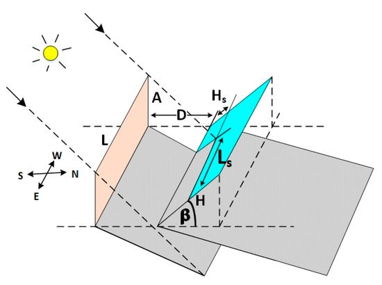
Figure 1.
The inclined collector behind wall .
Therefore,
where is the sun elevation angle, is the sun azimuth, and is the collector azimuth angle with respect to south, (+) eastward, and (−) westward. We denote:
For , the shadow is eastward and for , the shadow is westward.
The shadow length is , where
Therefore,
In the case of a saw-tooth roofs (see Figure 2), the shadow height and length, respectively, are obtained by setting and replacing with in Equations (3) and (6):
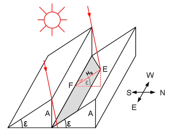
Figure 2.
The shading on a saw-tooth roof.
An inclined roof may contain modules placed flush along the roof width for which Equations (7) and (8) apply.
In the case of saw-tooth roofs in Figure 3, the height in Figure 2 is replaced with (see Equations (7) and (8)), obtaining the shadow height and length on the collector :
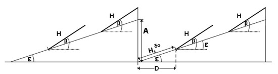
Figure 3.
The inclined collectors on an inclined roof.
The distance from the wall (see Figure 2) and the beginning of where the deployment starts at the bottom of the first collector, is determined by the shadow height (see Equation (7) and Figure 4), at noon () on the winter solstice [20]:
where is the site latitude and .
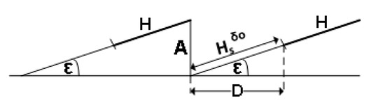
Figure 4.
The distance between wall and collector .
The distance from the wall becomes:
2.2. Numerical Results—Distance from Wall – Figure 4
Figure 5 shows the relationship between the distance and the inclination angle of the saw-tooth plane for different wall heights based on Equation (12).
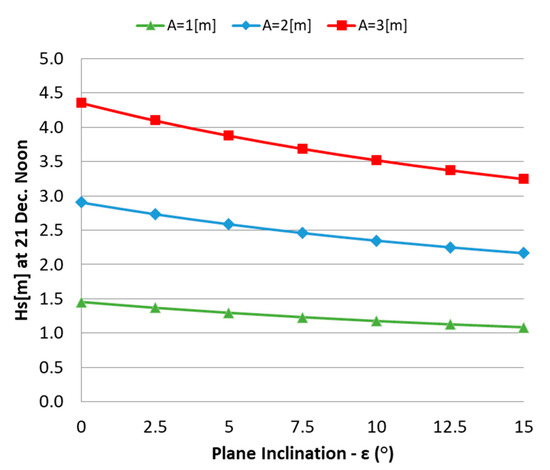
Figure 5.
The distance from wall to the first collector for the inclined planes , see Figure 4.
Shorter distances are needed from walls and fences to the PV collectors for steeper inclined roofs.
2.3. Numerical Results—Distance from Wall – Figure 3
Figure 6 shows the relationship between the distance and the inclination angle for a saw- tooth plane for different wall heights, , m, applying Equation (9).
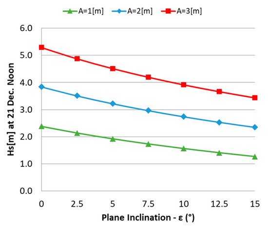
Figure 6.
The distance from wall to the first collector for inclined planes , see Figure 3.
Larger distances are required for higher walls.
3. Fence Shading
Figure 7 shows an inclined collector with an angle facing south and a vertical fenced wall oriented with an azimuth with respect to E-W direction. The shadow cast by the fence on the collector is developed in [4], Appendix B, providing expressions for the shadow angle and the length . For a vertical wall with an angle with respect to the E-W collector direction, the shadow angle and the distance respectively become:
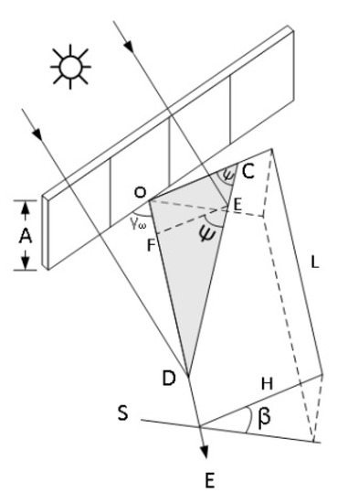
Figure 7.
The shading by fence on an inclined collector.
Therefore, the shaded area is:
To reduce the shading on the collectors, the collectors are shifted away from the fence by a distance . The shadow length becomes (see Equation (14)),
Numerical Results—Distance From Fence
The distance from the north-south vertical fence to the collector row is determined by the shaded area (see Equation (16)), i.e., by the shading losses. Figure 8 depicts the annual percentage energy shading losses with the distance from the fence for several heights (see Figure 7), for collector width , collector length , latitude , and inclination angle . Figure 8 pertains to a PV system bounded by two north-south vertical fences, one to the east and the second to the west of the collectors. If, for example, one agrees to accept a loss of in direct beam radiation, one may place the collectors away from a fence of height .
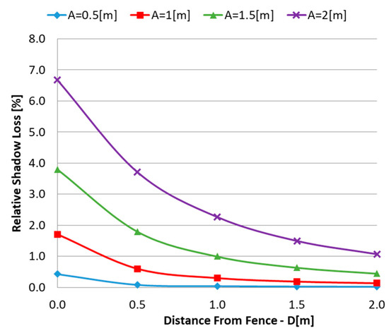
Figure 8.
The percentage annual energy shading loss of a collector with its distance from the fence, see Figure 7.
The shading losses decrease with an increase in the distance from obscuring objects; however, higher obscuring objects increase the shading losses.
4. Distance between Collector Rows
The shadow height and the length are developed in [4] for horizontal and inclined planes. In this section the distance between the collector rows is determined. The distance is calculated, based on the customary approach, by the shadow length on December 21, at noon [20]. One may obtain for an inclined plane, see Figure 9, the following distance:
where
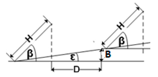
Figure 9.
Stepped collectors.
For a horizontal plane .
Numerical Results—Distance between Rows
Figure 10 shows the relationship between the distance and the inclination angle of the plane for collector width and inclination angles
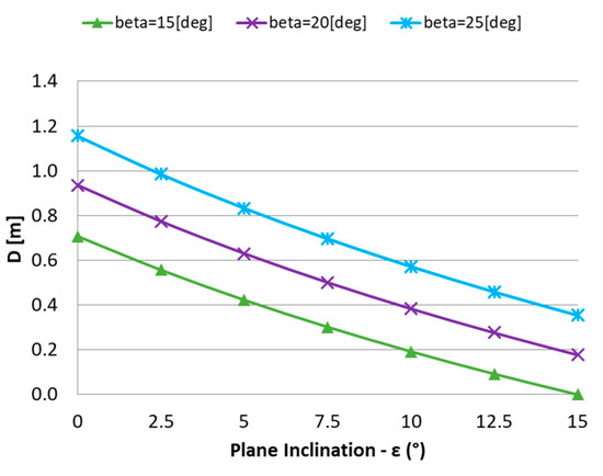
Figure 10.
The row distance for an inclined plane , see Figure 9.
Shorter row-to-row distances between the PV collectors are needed for steeper inclined roofs, and larger collector inclination angles require larger row-to-row distances.
5. Sloped Rooftops
Photovoltaic modules may be installed in multiple rows on sloped rooftops. Rooftops may be oriented at any azimuth. Figure 11 shows a PV system installed on a rooftop facing west with a slope and roof width (one side). The distance between the rows is denoted by and the row inclination angle is with respect to the roof plane. To fully utilize the roof width, the modules are rotated with an angle with respect to the roof length, creating a shift between the rows, the amount of which is given by:
where is the width of the PV modules.
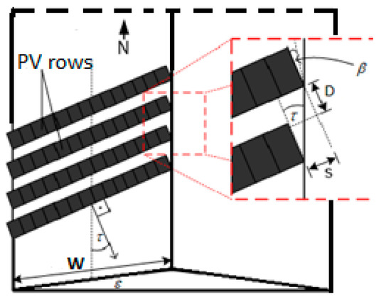
Figure 11.
The PV modules deployed on a sloped roof facing west.
Given and , one may calculate the optimal angles and to obtain the maximum annual incident irradiation per unit area on the PV module, based on the solar radiation data at a given location. The optimization was performed for , rows, , latitude , and for roof slopes to with increments of for two cases: (a) optimal and , and (b) optimal for (rows pointing due south for comparison). Mutual shading between rows was taken into account. The results are shown in Table 1.

Table 1.
Optimal angles and irradiation on a sloped roof facing west.
The left column indicates the roof slope , the second column is the optimal inclination angle of the PV modules with respect to the roof plane, the third column indicates the rotation angle of the rows relative to the roof length, and the fourth row is the annual global incident irradiation per square meter . For comparison, the optimization was also carried out for PV rows facing south (). The fifth column is the optimal inclination angle, the six column is the annual global incident irradiation per unit area, and the last column is the percentage difference between the two cases calculated by . Table 1 reveals that almost no gain in incident irradiation is obtained by rotating the rows on sloped roofs for ; however, a gain of about may be obtained by pointing the rows south-east with an angle .
Remark: Because of asymmetry in the solar radiation at the location, the optimal azimuth angle of the PV rows on a horizontal plane is positive, i.e., pointing to the south-west by .
6. Discussion
Rooftops are usually limited in area, and therefore the deployment of PV collectors on rooftops is densely designed. In addition, rooftops may contain objects obscuring the PV collectors, such as fences, walls, and other protruding objects. Mutual shading by collectors and shading by obscuring objects on the collectors reduce the direct beam incident radiation, and hence impair the generated energy of the PV system. Therefore, estimating the tolerated shading losses has to be taken into account in the design of the PV systems on rooftops. Consequently, the approach of designing PV systems on rooftops may be different than that for large PV systems on the ground. The present study deals mainly with the distance between the obscuring objects, like walls and fences, and the PV collectors encountered on different roof types affecting shading losses. These expressions may as well be applied to ground PV systems. The expressions for the appropriate distances may also be incorporated into optimization algorithms for optimized PV system designs. Literature on the shading of PV systems concentrate on mutual shading and the distances between the collector rows deployed on the ground, but they do not address shading and the distances from protruding objects encountered on rooftops. The present study focuses mainly on the distances from walls and fences.
7. Conclusions
The deployment of PV collectors on rooftops may encounter shading by adjacent collectors and by obscuring structures on the rooftops, resulting in a reduction in the generated electric energy. Increasing the row distance between the collector rows or increasing the distance from the obscuring structures (walls and fences) to reduce or avoid shading may not be an option because of limited rooftop area. The present study develops mainly analytical expressions for distances between walls and fences and PV collector rows for horizontal, inclined, and saw-tooth roofs. These expressions may also be applied to PV fields on the ground. Based on Figure 5, Figure 6, Figure 8 and Figure 10, the following conclusions may be drawn: (1) Shorter row-to-row distances between the PV collectors are needed for steeper inclined roofs. (2) Larger collector inclination angles require larger row-to-row distances. (3) Shorter distances are needed from walls and fences to the PV collectors for steeper inclined roofs; however, higher walls and fences require larger distances. (4) Shading losses decrease with an increase in the distance from obscuring objects; however, higher obscuring objects increase the shading losses. On fenced roofs, the shadow on the collectors depends on the fence height and azimuth, on the distance between the collectors and the fence, and on the collectors’ inclination angle. Higher annual incident irradiation may be obtained on sloped triangular roofs for PV modules deployed with angles pointing south-east and south-west, rather than due south.
Author Contributions
Conceptualization and methodology, J.A.; software, A.A. All authors have read and agreed to the published version of the manuscript.
Funding
This research received no external funding.
Conflicts of Interest
The authors declare no conflict of interest.
References
- Castellanos, S.; Sunter, D.A.; Kammen, D.M. Rooftop solar photovoltaic potential in cities: How scalable are assessment approaches? Environ. Res. Lett. 2017, 12, 125005. [Google Scholar] [CrossRef]
- Rinat, Z. Report says rooftop solar panels are sufficient to meet Israel’s energy goals. HAARETZ, 23 October 2017. [Google Scholar]
- Appelbaum, J.; Bany, J. Shadow effect of adjacent solar collectors in large scale systems. Sol. Energy 1979, 23, 497–508. [Google Scholar] [CrossRef]
- Bany, J.; Appelbaum, J. The effect of shading on the design of a field of solar collectors. Sol. Cells 1987, 20, 201–228. [Google Scholar] [CrossRef]
- Barra, O.; Conti, M.; Santamata, E.; Scarmozzino, R.; Visentin, R. Shadows’ effect in a large scale solar power plant. Sol. Energy 1977, 19, 759–762. [Google Scholar] [CrossRef]
- Jones, R.E., Jr.; Burkhart, J.F. Shading effect of collector row tilt toward the equator. Sol. Energy 1981, 26, 563–565. [Google Scholar] [CrossRef]
- Budin, R.; Budin, L. A mathematical model for shading calculations. Sol. Energy 1982, 29, 339–349. [Google Scholar] [CrossRef]
- Sadineni, S.B.; Boehm, R.F.; Hurt, R. Spacing analysis of an inclined solar collector field. In Proceedings of the ASME 2nd International Conference on Energy Sustainability, Jacksonville, FL, USA, 10–14 August 2008. [Google Scholar]
- Groumpos, P.P.; Kouzam, K.Y. A Generic approach to the shadow effect in large solar power systems. Sol. Cells 1987, 22, 29–46. [Google Scholar] [CrossRef]
- Elsayed, M.M. Monthly-averaged daily shading factor for a collector field. Sol. Energy 1991, 47, 287–297. [Google Scholar] [CrossRef]
- Elsayed, M.; AI-Turki, A. Calculation of shading factor for a collector field. Sol. Energy 1991, 47, 413–424. [Google Scholar] [CrossRef]
- Passias, D.; Kallback, B. Shading effects in rows of solar cell. Sol. Cells 1984, 11, 281–291. [Google Scholar] [CrossRef]
- Thakkar, N.; Cormode, D.; Lonij, V.P.; Pulver, S.; Cronin, A.D. A simple non-linear model for the effect of partial shade on PV systems. In Proceedings of the 2010 35th IEEE Photovoltaic Specialists Conference, Honolulu, HI, USA, 20–25 June 2010. [Google Scholar]
- Quaschning, V.; Hanitsch, R. Increased Energy yield of 50% at Flat Roof and Field Installations with Optimized Module Structures. In Proceedings of the 2nd World Conference and Exhibition on Photovoltaic Solar Energy Conversion, Vienna, Austria, 6–10 July 1998; pp. 1993–1996. [Google Scholar]
- Ma, X.S.; Yao, G.H.; Ye, L.J.; Zhi, X.F.; Zhang, S.M. Distance calculation between photovoltaic arrays fixed on sloping ground. J. Comput. Methods Sci. Eng. 2015, 15, 107–116. [Google Scholar] [CrossRef]
- Castellno, N.N.; Parra, J.A.G.; Valls-Guirado, J.; Manzono-Agugliaro, F. Optimal displacement of photovoltaic array’s rows using a novel shading model. Appl. Energy 2015, 144, 1–9. [Google Scholar] [CrossRef]
- Alsadi, S.Y.; Nassar, Y.F. A general expression for the shadow geometry for fixed mode horizontal, step-like structure and inclined solar field. Sol. Energy 2019, 181, 53–69. [Google Scholar] [CrossRef]
- Copper, J.K.; Sproul, A.B.; Bruce, A.G. A method to calculate array spacing and potential system size of photovoltaic arrays in urban environment using vector analysis. Appl. Energy 2016, 161, 11–23. [Google Scholar] [CrossRef]
- Annathurai, V.; Gan, C.K.; Baharin, K.A.; Ghani, M.R. Shading analysis for the siting of solar PV power plant. APRN J. Eng. Appl. Sci. 2006, 11, 5021–5027. [Google Scholar]
- Appelbaum, J.; Aronescu, A. The effect of sky diffuse radiation on photovoltaic fields. J. Renew. Sustain. Energy 2018, 10, 033505. [Google Scholar] [CrossRef]
© 2020 by the authors. Licensee MDPI, Basel, Switzerland. This article is an open access article distributed under the terms and conditions of the Creative Commons Attribution (CC BY) license (http://creativecommons.org/licenses/by/4.0/).